EP2950290A1 - Method for providing traffic information - Google Patents
Method for providing traffic information Download PDFInfo
- Publication number
- EP2950290A1 EP2950290A1 EP14290156.0A EP14290156A EP2950290A1 EP 2950290 A1 EP2950290 A1 EP 2950290A1 EP 14290156 A EP14290156 A EP 14290156A EP 2950290 A1 EP2950290 A1 EP 2950290A1
- Authority
- EP
- European Patent Office
- Prior art keywords
- sensors
- sensor
- information
- vehicles
- network
- Prior art date
- Legal status (The legal status is an assumption and is not a legal conclusion. Google has not performed a legal analysis and makes no representation as to the accuracy of the status listed.)
- Withdrawn
Links
Images




Classifications
-
- G—PHYSICS
- G08—SIGNALLING
- G08G—TRAFFIC CONTROL SYSTEMS
- G08G1/00—Traffic control systems for road vehicles
- G08G1/01—Detecting movement of traffic to be counted or controlled
- G08G1/0104—Measuring and analyzing of parameters relative to traffic conditions
- G08G1/0137—Measuring and analyzing of parameters relative to traffic conditions for specific applications
- G08G1/0141—Measuring and analyzing of parameters relative to traffic conditions for specific applications for traffic information dissemination
Definitions
- Information about road conditions is commonly based on weather status and forecast reports, occasionally completed by information from few sensors in the road infrastructure.
- Information about traffic flow is commonly based on data from street cameras, radar sensors or inductance loops which are built in the streets. All these sensors and their deployment are costly. Deployment of inductance loops usually involves roadwork, e.g., grinding and repair of street covering.
- Traffic information comprises in particular information about road conditions such as humidity or ice on the road surface caused by the weather, information about the quality of the road surface which might be affected by holes etc., information about dangerous spots or curves of a road, and information about vehicles driving on one or more roads such as the number and/or size of the vehicles.
- the objective of the invention is achieved by a method for providing traffic information, the method comprising gathering information by a network of sensors provided in and/or on one or more roads or road segments and processing the gathered information.
- the objective of the invention is further achieved by a system for providing traffic information, the system comprising a network of sensors provided in and/or on one or more roads or road segments, wherein the network of sensors is adapted to gather information, wherein one or more of the sensors of the network of sensors and/or a central server are adapted to process the gathered information.
- the objective of the invention is further achieved by a server for providing traffic information, wherein the server is adapted to process information gathered by one or more sensors of a network of sensors provided in and/or on one or more roads or road segments.
- the server is also referred herein as a central server.
- a computer comprises in particular a processor and a memory.
- a computer adapted to the implementation of the respective device might be implemented in particular in the one or more sensors, in the central server, in the one or more vehicles and/or in a relay of the network of sensors.
- the present invention might be implemented by hardware, software or combination of hardware and software.
- central server instead of one central server, two or more central servers might be used.
- two or more relays might be used.
- a plurality of relays is used, distributed on a plurality of road segments, respectively.
- the sensors used for the network of sensors are preferably low cost devices and fabricated in huge quantity.
- a sensor is preferably equipped with a processor, a sender or transmitter, a receiver, and/or transceiver.
- the sensors are provided in the one or more roads by mixing the sensors into the hot tarmac, when the road surface is deposited.
- the sensors are provided on the one or more roads by mounting the sensors into the road surface, in particular by nailing or gluing the sensors into the road surface.
- the mounting of the sensors considers the usage scenario and as well the chosen energy supply concepts of the sensors.
- the senor are equipped with a long life time battery, this means one battery for each sensor.
- the life time of the battery exceeds ten years.
- the sensor energy consumption is very low and the sensor may be operable for ten years or more which is long enough to span the life time of an averagely used road coating.
- the sensors are equipped with energy harvesting devices, in particular piezoelectric elements or photovoltaic elements.
- the sensors are energized via microwave.
- 5 sensors per square meter are provided in and/or on the roads.
- one or more sensors of the network of sensors gather information on local road conditions, in particular measurements on humidity, temperature, pressure and/or chemicals.
- one or more sensors of the network of sensors gather information about one or more vehicles passing the one or more sensors, in particular number of vehicles, weight, size, speed, acceleration and/or driven track.
- a sensor gathers information about a passing vehicle when the vehicle passes a sensor.
- a sensor gathers information about a passing vehicle by means of a piezoelectric element when the vehicle drives over the sensor.
- the pressure which the vehicle causes on the piezoelectric element indicates the weight of the vehicle and therefore provides to the sensor information that a vehicle is passing the sensor and the weight of the vehicle.
- the energy which is provided by the pressure of the vehicle driving over the sensor might also be used for generating energy for the operation of the sensor.
- the sensor might be equipped with a battery, in particular re-chargeable battery which charges the energy provided by the piezoelectric element.
- the gathered information is processed locally by the network of sensors.
- the information might be processed only by the sensor which gathered the respective information.
- the information might be processed by one or more further sensors, preferably in adjacency of the sensor which gathered the respective information, after information exchange with said sensor.
- the information gathered by a sensor might be exchanged with a plurality or all sensors of the network of sensors for further processing.
- the gathered information is transmitted from the one or more sensors to a central server for further processing.
- control information is sent to one or more vehicles, in particular via a direct communication link between one or more sensors of the network of sensors and the one or more vehicles, via a relay or via a central server.
- control information comprises one or more of the group: alarm information for approaching vehicles about, in particular local, poor road conditions, in particular wetness, ice, spilled oil, mud; information about recommended optimal tracks to avoid dangerous local spots or trails on the road surface; information about recommend optimal tracks through dangerous bends; information about learnt tracks taken by vehicles driving beforehand through an area and recommendations based on the experiences gained from earlier passages, possibly considering physical properties, e.g. weight, of the vehicles.
- the experiences might be evaluated by the central server, the one or more vehicles or the network of sensors, wherein evaluation is in particular providing control information based on the previous experiences.
- one or more sensors of the network of sensors are calibrated by one or more vehicles passing the one or more sensors and transmitting a local position to a memory of the one or more sensors.
- the local position of a sensor is defined by the geo-coordinates of a sensor.
- a vehicle determines the local position of a sensor when passing the respective sensor.
- a vehicle when used to calibrate one or more sensors might be termed a calibration vehicle.
- a vehicle is equipped with a large antenna to communicate with the one or more sensors.
- the step of calibration comprises activating, by a calibration vehicle, the sensor of which the local position is to be determined when passing the sensor, causing the sensor to transmit the address of the sensor to the calibration vehicle, determining geo-coordinates of the sensor corresponding to the address of the sensor, in particular via GPS, triggering a calibration sequence in the sensor and transmitting the geo-coordinates to a memory of the sensor, which is preferably a static memory.
- the geo-coordinates of a sensor are determined from a velocity vector indicating a speed of a calibration vehicle by amount and direction and from a time measured between passing - by the calibration vehicle - a sensor of which the geo-coordinates are already known and passing - by the calibration vehicle - a sensor of which the geo-coordinates are to be determined.
- a calibration vehicle determines the local position of a sensor by means of a GPS receiver, when passing the respective sensor.
- the geo-coordinates of the sensor are stored in the memory of the sensor and can be transmitted to a vehicle and/or to a central server, where the geo-coordinates of the sensor might be stored in addition, suitable for further information exchange within the system, in particular vehicles, sensors.
- a calibration vehicle determines the local position of a sensor by means of its relative position to a first and a second further sensor of the network of sensors of which the local positions are already known.
- the calibration vehicle determines the geo-coordinates of a sensor of which the geo-coordinates are to be determined from a first further sensor of which the geo-coordinates are already known and a second further sensor of which the geo-coordinates are already known.
- a sensor of which the local position is already known is used as reference sensor.
- (further) sensors of which the local positions are already known are used as (further) reference sensors.
- one or more vehicles determine the geo-coordinates of a sensor, of which the local position is to be determined, by means of its relative position to a first further sensor and a second further sensor of which the geo-coordinates are already known, in particular by deriving the geo-coordinates of the sensor, of which the local position is to be determined, from its relative position to the first and the second further sensor of which the already known geo-coordinates are used as reference positions and from timing measurements and/or known velocity or speed limit information.
- the calibration vehicle triggers a clock in all sensors when passing the first further sensor (reference sensor) of which the local position is already known, stops a time when passing the second further sensor of which the local position is already known, determines a velocity vector of the calibration vehicle by amount of the velocity and direction of the velocity and measures the time when passing the sensor of which the local position is to be determined and determines the local position of that sensor from the measured time and the determined velocity vector.
- the local position of a next sensor might be determined, either from the measurements of time and velocity with reference to the first sensor or the last passed sensor of which the geo-coordinates are already known.
- the calibration vehicle triggers a clock which is extern to the sensors.
- the clock is included in the calibration vehicle itself.
- the calibration vehicle comprises a clock and triggers the clock when passing the reference sensor. Then the calibration vehicle stops a time when passing the second further sensor of which the local position is already known, determines a velocity vector of the calibration vehicle by amount of the velocity and direction of the velocity and measures the time when passing the sensor of which the local position is to be determined and determines the local position of that sensor from the measured time and the determined velocity vector, preferably according to the above implementation and formula.
- only the stop times of the passed sensors have to be determined, stored and processed.
- the implementation of the sensors is simpler, the sensors need less energy and the cost of the sensors is less than in the embodiment where all sensors are equipped with individual sensors.
- the amount of the velocity vector is pre-defined, i.e. already known, and therefore only the direction of the velocity vector is determined from the geo-coordinates of the first and second further sensor of which the local positions are already known.
- the speed is determined by a speed limit and the time determined as a mean value of a plurality of measurements.
- the distribution of the speeds driven by a plurality of vehicles is peaking at the speed limit value. Therefore, by statistically reasons, the speed of the vehicles correspond to the known speed limit value.
- the time between passing - by a plurality of vehicles used in this embodiment as calibration vehicles - two sensors is determined by the mean value of a plurality of measurements of the time for the vehicles passing two sensors subsequently and storing the measurements in a memory.
- the measurements or measurement results are stored in the memory of the sensor of which the local position is to be determined.
- the measurements/ measurement results are not stored in the sensors, but in a further memory extern to the sensors, for example in the vehicle; in this example embodiment, it has to be ascertained that the measurement results can be assigned to an individual sensor or the individual sensors, respectively.
- the distance between the two sensors is determined by multiplying the mean value of the time interval distribution, i.e.
- the distance between the two sensors can be determined. If the geo-coordinates of one of the two sensors are already known, the geo-coordinates of the other of the two sensors can be determined.
- the local position of the sensors is determined.
- the local position of sensors is stored in a memory of the respective sensors and/or preferably in the memory of the central server.
- the local position of sensors might be transmitted to one or more vehicles as soon as the vehicles need or want to know the local position of sensors.
- the one or more vehicles might store the local position of one or more sensors in a memory included in the vehicle.
- the network of sensors can be used to send control information to one or more vehicles driving on the roads where the network of sensors is installed.
- the step of sending control information to the one or more vehicles comprises transmitting one or more signals to the one or more vehicles guiding the one or more vehicles on a recommended track.
- any other control information may be sent, like e.g. commands for acceleration or deceleration (breaking), chassis adjustments, etc.
- control information might be information of the total track recommended to take by the vehicle.
- the control information might be transmitted to the vehicle by the central server and/or one or more sensors.
- the control information might be stored in the vehicle and used to guide the vehicle on the recommended track.
- the one or more signals are transmitted by the one or more sensors, usually by a plurality of sensors, guiding the vehicle on a recommend track.
- the one or more signals are either attracting or repelling signals, wherein the signals contain directional vector information, wherein the directional vector information of the signals is added to a vector sum indicating the recommended track.
- the added vector information is implemented as a field of vectors or vector field indicating the recommended track for a vehicle.
- the vehicle is guided on the road such as a magnetic piece is attracted by a magnetic field attracted by the magnetic forces resulting from attracting and repelling magnetic lines.
- the information exchange between the network of sensors, the vehicles, the central server and among the sensors of the network of sensors is implemented wirelessly, in particular based on a wireless platform exploiting low latency machine to machine, M2M, communication.
- the information transfer within the network of sensors is based on a wireless platform exploiting low latency machine to machine, M2M, communication.
- the information transfer between the one or more sensors and the central server is based on a wireless platform exploiting low latency machine to machine, M2M, communication.
- the information transfer from one or more sensors and/or from the central server to the one or more vehicles and in the opposite direction is based on a wireless platform exploiting low latency machine to machine, M2M, communication.
- the information is transferred between the one or more sensors and the one or more vehicles via a direct link or via a relay which is mounted at the side of the one or more roads.
- the step of further processing information by the central server comprises to return information about traffic density for traffic control and traffic management and/or to give indication about passing vehicles, in particular considering their weight e.g. for toll pricing.
- the sensors gather information on one or more vehicles when a respective vehicle passes a sensor, wherein the respective vehicle drives over the respective sensor.
- a sensor gathers information about an identity of a vehicle, in case the vehicle transmits information about the identity of the vehicle to the sensor.
- the identity might be defined by the number plate and/or by the number of the engine or chassis frame.
- the network of sensors gathers information about the location and/or or direction of the taken track of the one or more vehicles driving over the roads in which the network of sensors is provided.
- a vehicle is preferably a car, a bus or a motorbike.
- the sensors are provided in an abundant quantity. Therefore, even in case of failure of part of the sensors, e.g. caused by wear out or erosion, the remaining sensors provide information with sufficient accuracy.
- a partial damage or change of position of a part of the sensors is healed by an autonomous self calibration.
- the information gathered by the sensors is implemented as a system of equation parameters.
- the equations comprise parameters derived from the information gathered by the sensors as described throughout the description such as e.g. vehicles by number and weight, direction, velocity, i.e. speed, possibly identity of the vehicles, position, time corresponding to position, track and information about the road conditions, such as humidity etc.
- the self calibration comprises excluding measurements of sensors based on logical considerations, in particular based on contradictive measurements, and/or executing a re-calibration of sensors.
- the information of the network of sensors is supplemented by information of devices external to the network of sensors.
- devices external to the network of sensors comprise radar stations and/or further monitoring devices gathering information of vehicles and/or of road conditions.
- the devices external to the network of sensors feed their information to the network of sensors, preferably to the central server.
- the information provided from the external devices might be used to supplement and/or verify the information provided by the network of sensors.
- the information gathered by the network of sensors might be used to supplement and/or verify the information of devices external to the network of sensors.
- Figure 1 shows a network of sensors 1 or a part of the network of sensors 1 which are provided in a road or on a road, or more specifically in or on the road segment 2, which is depicted illustratively in the figure 1.
- a central server 4 is installed in adjacency to the road 2 .
- the sensors 1 While the vehicle 3 drives over the road 2, the sensors 1 will gather information about the vehicle 3 and further will also provide information to the vehicle 3. However, before the sensors 1 can be used to gather and provide information, the sensors 1 need to be calibrated.
- the local position of the sensors 1 is determined and stored, for example into the sensors 1 and/or in the central server 4. This means the storage of the local position of the sensors 1 can be located only within the respective sensors 1 or only in the central server 4 or both within the sensors 1 and in the central server 4.
- a sensor 1 stores only its own local position
- a sensor 1 stores its own local position and in addition the local position of further, in particular adjacent, sensors 1.
- the local position of the sensors 1 is determined and stored, because the information gathered by the sensors 1 and provided by the sensors 1 is preferably valuable, in particular if the information is assigned to the location of the respective sensor 1, which gathered or provided the information. For example, if a sensor 1 determines that the road 2 in which the sensor 1 is situated is wet, so the information is preferable valuable if the information that the road 2 is wet is combined with the local position of the sensor 1 indicating likewise the exact location on the road 2 where the road 2 is wet.
- one or more vehicles 3 pass the sensors 1 and determine and transmit the local position to a memory of the respective sensor 1 of which the one or more vehicles 3 have determined the local position.
- the local position might be assigned to the sensor ID and both data stored in a memory located in the server or cloud.
- a specific sensor 1 there are primarily two manners for calibrating a specific sensor 1 and similarly the other sensors 1 of network of sensors 1.
- the local position of a sensor 1 is determined absolutely or directly, in particular via GPS.
- the local position of a sensor 1 is determined in relation to a further sensor 1 (dubbed "reference sensor") of which the local position is already known.
- the two manners are used alternatively, and exceptionally combined for verification purposes.
- FIG. 2 illustrates the first manner, where the local position of a sensor 1 is determined absolutely or directly by a vehicle 3, which might be termed a calibration vehicle 3 as it is used to calibrate the sensor 1 and similarly the network of sensors 1.
- the calibration vehicle 3 drives over the road 2.
- the sensor 1 of which the local position is to be determined is activated, which is symbolized by waves indicating also the communication between the sensor 1 and the vehicle 3.
- a vehicle 3 is equipped with one or more transceivers 14 (see figures 5 and 6 ), preferably comprising one or more antennas with a large range.
- the calibration vehicle 3 causes the sensor 1 to transmit the address of the sensor 1 to the calibration vehicle 3.
- the address of the sensor 1 might be the number of the sensor 1, in particular a MAC address or any name or number of the sensor 1 by which the sensor 1 can be, preferably unambiguously, identified.
- the calibration vehicle 3 determines the local position of the sensor 1. More specifically, the calibration vehicle 3 determines the geo-coordinates of the sensor 1 corresponding to the address of the sensor 1, this is calibration vehicle 3 determines the geo-coordinates of the sensor 1 which is identified by the address of the sensor 1. In the embodiment which is illustrated in figure 2 , the calibration vehicle 3 determines the local position of the sensor 1 by means of a GPS (Global Position System) receiver. As soon as the calibration vehicle 3 passes over the sensor 1, and the activated sensor 1 has transmitted the address of the sensor 1 to the calibration vehicle 3, the calibration vehicle 3 determines the geo-coordinates by means of a GPS receiver which indicates the geo-coordinates of the calibration vehicle 3 situated above the sensor 1 at this moment and thus the geo-coordinates of the sensor 1.
- GPS Global Position System
- any system by which geo-coordinates can be determined might be used.
- the calibration vehicle 3 preferably triggers a calibration sequence in the sensor 1 which thereby is informed that it will receive its geo-coordinates for calibration of the sensor 1, so that the sensor is now ready for receiving its geo-coordinates.
- the vehicle transmits the geo-coordinates to the sensor 1 to a memory, preferably to a static memory, of the sensor 1 which accordingly stores its geo-coordinates in the memory.
- the memory of the sensor now contains the geo-coordinates of the sensor 1 assigned to the address of the sensor 1.
- the geo-coordinates might be assigned to the sensor ID and both data stored in a memory located in the server or cloud.
- Figure 3 illustrates the second manner for calibrating the sensors 1 of the network of sensors.
- the calibration vehicle 3 determines the local position of a sensor 1 by means of its relative position to a first further reference sensor 1 and a second further reference sensor 1 of which the local positions are already known.
- the network of sensors 1 comprises in the road 2 one or more reference sensors of which the local positions are already known, for example because their geo-coordinates have been determined beforehand according to method 1, in particular via a GPS receiver by a calibration vehicle 3.
- the local positions of sensors of which the geo-coordinates are not yet known are determined in relation to sensors of which the geo-coordinates are known.
- the sensors of which the geo-coordinates are already known are depicted in figure 3 by squares, of which a first sensor of which the geo-coordinates are already known is specified by the reference sign 1 a and a second sensor of which the geo-coordinates are already known is specified by the reference sign 1 b.
- the sensor of which the geo-coordinates are to be determined is specified by reference sign 1c.
- the second manner consists in short in that the calibration vehicle 3 passes the first sensor 1 a and the second sensor 1 b of which the geo-coordinates are already known, determines its own velocity in terms of amount and direction and calculates the local position of the sensor 1c from the distance between the sensor 1 b and the sensor 1c.
- the geo-coordinates of the sensor 1c are determined from a velocity vector indicating a speed of the calibration vehicle 3 by amount and direction and from a time measured between passing - by the calibration vehicle 3 - the sensor 1 b of which the geo-coordinates are already known and passing - by the calibration vehicle 3 - the sensor 1 c of which the geo-coordinates are to be determined.
- the second method is implemented in more detail by the following steps.
- the calibration vehicle 3 triggers a clock in all sensors 1, including sensors 1 a, 1 b, 1 c, when passing the first sensor 1 a of which the local position is already known.
- the calibration vehicle 3 stops the time at its own clock as a semi-result, this means the calibration vehicle 3 measures the time for the passage from the first sensor 1 a to the second sensor 1 b. From the geo-coordinates of the first sensor 1 a and the second sensor 1 b and the measured time for the passage from first sensor 1 a to second sensor 1 b, the calibration vehicle 3 determines a velocity vector of the calibration vehicle by amount of the velocity and direction of the velocity.
- the calibration vehicle 3 continues its driving with the determined speed indicated by the velocity vector by amount and direction. As soon as the calibration vehicle 3 passes a sensor of which the local position is to be determined because it is not yet know, here sensor 1 c, the calibration vehicle 3 determines the time between passing the sensor 1 b and the sensor 1c. From the time for the passage between sensor 1 b and sensor 1 c and from the velocity vector the calibration vehicle 3 determines the local position of sensor 1c.
- the calibration vehicle determines the distance between sensor 1 b and sensor 1 c and further from the geo-coordinates of sensor 1 b which are already known and the distance between sensor 1 b and sensor 1 c and the direction of the velocity vector, this means the direction of the driving of the calibration vehicle 3, the calibration vehicle 3 determines the geo-coordinates of sensor 1c.
- this holds under the assumption that the distance between sensors 1 a, 1 b and 1 c is sufficiently short so that the vehicle passes the sensor field at nearly constant speed. Otherwise, preferably, additional reference sensors need to be inserted and consequently are implemented.
- the amount of the velocity vector is pre-defined, i.e. already known (e.g. because the vehicle drives with the pre-defined speed), and therefore only the direction of the velocity vector is determined from the geo-coordinates of the first 1a and second 1b further sensors of which the local positions are already known.
- the clocks need not to be located in the sensors but a single clock may be implemented on the server and the stop times might be assigned to the individual sensors and stored in the server or in the cloud.
- the speed is determined by a speed limit for vehicles passing the road or road section and the time is determined as a mean value of a plurality of measurements.
- the vehicles 3 are used contemporaneously for calibration of the sensor 1c and similarly for other sensors 1 of which the geo-coordinates are to be determined.
- the distribution of the speeds driven by a plurality of vehicles 3 is peaking near the speed limit value.
- the mean value of the speed distribution of the vehicles 3 correspond to the known speed limit value.
- the time between passing by a plurality of vehicles 3 two sensors 1 is determined by the mean value of a plurality of measurements of the time for the vehicles 3 passing two sensors 1 and storing the measurements in a memory, in particular in the memory of the sensor 1 of which the local position is to be determined, here 1c.
- the distance between the two sensors, here between sensor 1 b and sensor 1 c is determined by multiplying the mean value of the time interval distribution, i.e. of the plurality of measurements of the time, with the speed corresponding to the speed limit value. Thereby, the distance between the two sensors 1 b and 1 c can be determined.
- the geo-coordinates of sensor 1c can be determined.
- an assumption is made that the distance between sensor 1 b and sensor 1 c is short and the vehicles drive from sensor 1b to sensor 1c in a straight direction, in particular in the direction which is determined from the passage from sensor 1a to sensor 1b.
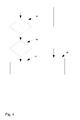
- FIG. 4 depicts a schematic view of some of the steps of the second manner for calibrating sensors 1 of the network of sensors 1.
- a first step 9 it is determined if a vehicle 3 is detected by a sensor 1. If this is not true, the step is repeated, until a vehicle 3 is detected. If this is true, it is proceeded to step 10. If a vehicle 3 is detected, it is determined in step 10, if the clock in the sensor 1 is running. If this is true, the manner proceeds to step 11, the clock is stopped, the time is stored and the distance is calculated according to the algorithm presented above. If the clock in the sensor 1 is not running, the time cannot be stopped by the respective sensor 1. Therefore, the method proceeds to step 12, which is to send a clock start command to other sensors 1.
- the time can be determined by the respective other sensor 1 and the distance can be calculated, so that in case the geo-coordinates of the sensor 1 which the vehicle 3 passed previously are known, the geo-coordinates of the other sensor 1 can be calculated.
- the manner of calibrating the network of sensors 1 by a plurality of vehicles 3 passing over the sensors 1 of the network of sensors 1 is also based on the consideration that by the many vehicles 3 the sensors 1 of network of sensors 1 will be calibrated stepwise, i.e. after a certain time period as soon as enough vehicles have been passed over the sensors and implements the calibration steps.
- a vehicle can not calculate the geo-coordinates of a sensor 1, because also the geo-coordinates of the sensor 1, which the vehicle passed previously are also not known.
- the sensors 1 of which the geo-ordinates are not yet known will be calibrated departing from the sensors 1 of which the geo-ordinates are already known.
- the further sensor 1 is thereby calibrated, this is its geo-coordinates are determined and stored. Its geo-coordinates might be stored in the memory of that sensor 1. Alternatively, the geo-coordinates may be stored together with the assigned sensor ID in a memory located in the server or cloud. Consequently, when a vehicle 3 then passes the later sensor 1 and drives then over a next sensor 1 of which the geo-ordinates are to be determined, the vehicle 3 can determine the geo-coordinates of this sensor 1, because the geo-coordinates of that sensor 1 before had been already determined as described.
- the further sensors 1 of which the geo-coordinates are to not yet known will be determined consequently, step-by-step, so that in the end in principle all sensors 1 of the network of sensors 1 are calibrated.
- the method of providing traffic information as described herein is nevertheless applicable, only the degree of accuracy of the information is a little bit lower as a sensor 1 which is not calibrated is usually regarded as non-existing, because preferably only information in connexion with the local position of a respective sensor 1 is valuable information.
- the sensors 1 can be used to gather and provide traffic information.
- the sensors 1 of the network of sensors 1 gather information on local road conditions, in particular measurements on humidity, temperature, pressure and/or chemicals.
- a sensor 1 can indicate that exactly at the local position where the sensor 1 is situated, the road 2 is wet or dry.
- the information about the kind of road condition e.g. wet or dry, can be provided with a high spatial accuracy.
- the sensors 1 gather information about the vehicles 3 driving over the road and thereby over the sensors 1.
- the sensor 1 detects the vehicle 3, because the sensor 1 is equipped with elements which detect in particular the pressure which is provided on the sensor1 by the weight of the vehicle 3 when driving over the sensor 1.
- one or more further ways of detecting one or more vehicles 3 by the sensor 1 are implemented, in particular inductive, optical and acoustical.
- the sensor 1 detects a vehicle 1 by means of inductive effect caused by the passing vehicle 1 in the sensor 1 which is therefore equipped with inductive sensitive elements, e.g. semi-conductive elements.
- the sensor 1 detects a vehicle 1 by optical means, e.g.
- the sensor 1 detects a vehicle 1 by by acoustical means, e.g. by semi-conductive elements which are sensitive for acoustical waves caused by the passing vehicle 3.
- a vehicle is equipped by means which transmit optical, acoustical or further signals for being detected by the sensors 1.
- the sensors 1 and similarly, the sensors 1 of the network of sensors 1 gather information about the traffic on the roads where the network of sensors 1 is provided.
- the traffic information gathered thereby by the network of sensors 1 is in particular number, weight, size, speed, acceleration and/or driven track of the one or more vehicles 3 driving over the roads 2.
- the sensors 1 might exchange, and preferably store, the information gathered by each of the sensors 1, and in particular in case the vehicle 3 identify themselves to the sensors 1 when passing over the sensors 1, parameters such as acceleration and/or driven track of a specific vehicle 3 can be determined.
- the gathered information is processed locally by the network of sensors 1.
- a sensor 1 might process only the information which it has gathered itself.
- a sensor 1 exchanges information with other sensors 1, which might be a certain group of adjacent sensors 1 or in principle all sensors 1 of the network of sensors 1.
- information gathered by the sensors 1 is transmitted from the sensor 1 to a central server 4 for further processing.
- a central server 4 is already depicted in figure 1 .
- the central server 4 might collect the information gathered and transmitted from the sensors 1.
- the central server 4 might compare the information transmitted from a first group of sensors 1 of the network of sensors 1 with a second group of sensors 1 of the network of sensors 1.
- the central server 4 might evaluate the information, e.g. by determining from the vehicles 3 counted and/or monitored by the one or more sensors 1 the total amount of vehicles 3 and/or the identity of the vehicles 3 driving on the road 2 and/or in a specific direction.
- the central server 4 might be able to provide a more global view of the traffic on the roads 2 in which the network of sensors 1 is installed.
- the sensors 1 themselves might evaluate the information in the way described in context of the central server 4, in case the processing and memory storage capacity of the sensors 1 is sufficiently large.
- a central server 4 which evaluates the information gathered by the sensors 1.
- the step of processing information comprises sending control information to one or more vehicles 3.
- the control information is preferably provided by the central server 4 for more complex evaluation.
- the sensors 1 might generate control information.
- the control information might in particular be information to control the traffic by e.g. directing one or more vehicles 3 on a determined track or use particular roads 2 thereby avoiding traffic jam for example.
- control information is preferably generated by the central server 4, the control information might be transmitted from the central server 4 via the sensors 1 to the vehicles 3. Further, control information might be generated by one or more sensors 1 and transmitted from the one or more sensors 1 to the one or more vehicles 3. Further, control information might be transmitted directly from the central server 4 to the one or more vehicles 3.
- the one or more vehicles 3 are equipped with one or more transceivers 14 ( Fig. 5 ).
- control information might be transmitted to the one or more vehicles 3 via a direct communication link between the one or more vehicles 3 with the central server 4. Alternatively or in addition, control information might be transmitted from the central server 4 via one or more sensors 1 to the one or more vehicles 3.
- control information might be transmitted to the one or more vehicles 3 via a direct communication link between the one or more sensors 1 and the one or more vehicles 3 ( figure 5 ).
- control information might be transmitted to the one or more vehicles 3 via a communication link between the one or more sensors 1 and the one or more vehicles 3 via the central server 4.
- control information might be transmitted via a relay 5 ( figure 6 ).
- the relay 5 might be mounted at the side of the road, e.g. on a limiting post, a sign post or a lamp post or on any further item, for example a brickwall or a tree.
- the information transfer between any of: the one or more vehicles 3, the one or more sensors 1, the central server 4, this means in particular from and/or to the vehicles 3, from and/or to the one or more sensors 1, from and/or to the central server 4 and from and/or to one or more of the sensors to one or more of the sensors 1 might be implemented directly or via a relay and/or via the central server 4.
- the control information comprises alarm information for approaching vehicles 3 about poor road conditions, in particular wetness, ice, spilled oil, mud on the road 2 where the vehicles are driving or where the vehicles are approaching.
- the control information comprises information about recommended optimal tracks to avoid dangerous local spots or trails on the surface of the road 2.
- the control information comprises information about recommended optimal tracks through dangerous bends of a road 2.
- the control information comprises information about learnt tracks taken by vehicles 3 driving beforehand through an area and recommendations based on the experiences gained from earlier passages, in particular considering weight of the vehicles 3.
- the network of sensors 1 might be implemented as a learning or self-learning network.
- the sensors 1 store information gathered from previous passing vehicles 3, in particular dangerous spots causing accidents or at least dangerous situations which might be detected from extremely fast reduction of speed of driving vehicles 3.
- This information is stored in the one or more sensors 1 and/or or in the central server 4, evaluated by the one or more sensors 1 and/or by the central server 4 and the evaluated information is stored in the one or more sensors 1 and/or in the central server 4.
- the evaluated information is then used as control information for approaching vehicles 3.
- the control information might in this case comprise a warning for vehicles 3 driving on a particular road of a dangerous curve thereby suggesting the vehicles 3 to slow down their speed to thereby avoid a dangerous situation.
- the step of sending control information to a vehicle 3 comprises transmitting one or more signals 6a, 6b to the vehicles 3 guiding the vehicles 3 on a recommended track 7.
- Figure 7 depicts a vehicle 3 driving on a road 2 in upward direction.
- a plurality of sensors 1 are provided.
- the sensors have gathered and now stored information about the road surface, in particular if the road surface is dry or wet.
- the sensors 1 have detected that the road surface is dry with the exception of a frozen puddle 13, where the surface is wet or even iced. Therefore, the frozen puddle 13 has to be avoided, because driving there is dangerous.
- the gathered information is preferably exchanged for further processing with the central server 4 and/or adjacent sensors 1 of the network of sensors 1.
- the processed information is exchanged with and within the sensors 1 in and around the frozen puddle 13. Based on the processed information, the sensors 1 send signals to an approaching vehicle 3.
- the signals sent to the vehicle 3 are either attracting signals 6a or repelling signals 6b.
- the sensors 1 which are located within the frozen puddle 13 send repelling signals 6b. These are signals which direct the vehicle 3 away from the frozen puddle 13.
- the sensors 1 outside the frozen puddle 13 send attracting signals 6a and the sensors 1 within the frozen puddle 13 send repelling signals 6b without exchanging the information gathered by the respective sensors 1 with the central server 4 and/or with further sensors 1.
- Each sensor 1 sends signals independently from the further sensors 1 without the sensors 1 exchange the gathered information.
- a sensor 1 within the frozen puddle 13 sends a repelling signal 6b, whereby preferably the direction of the signal 6b considers the local position of the sensor 1, so the repelling signal 6b guides away from the frozen puddle 13 in the direction of e.g. the middle of the road 2 and not in direction outside the road 2.
- a sensor 1 outside the frozen puddle 13 sends an attracting signal 6a, preferably considering the local position of the sensor 1.
- Each sensor might preferably consider, in which direction a vehicle 3 drives in principle, this means in figure 7 up or downwards for generating the signals 6a and 6b respectively.
- the signals 6a, 6b contain directional vector information.
- the signals 6a, 6b contain a direction for the vehicle 3 where to go.
- the directional vector information of the signals 6a, 6b is added to a vector sum 8 indicating the recommended track 7.
- the vehicle 3 receives the attracting signals 6a and the repelling signals 6b as sent by the sensors 1 and implements the addition of the vector information to the vector sum 8 in a processor of the vehicle 3.
- the attracting signals 6a and the repelling signals 6b are transmitted from the sensors 1 to the central server 4, which adds the directional vector information of the attracting signals 6a and of the repelling signals 6b to a vector sum 8, thus to a resulting vector indicating the recommended track and then sends the resulting vector to the vehicle 3.
- a relay 5 might be used.
- Figure 7 indicates the recommended track which the vehicle 3 will take due to the resulting vector 8 corresponding to the vector sum 8.
- the resulting vector 8 considers the direction of the driving vehicle 3 and gives a correction signal to the direction in which the vehicle 3 is driving.
- the resulting vector 8 indicates the recommended track directly, and the vehicle 3 will process a correction of its direction to follow the recommended track 7.
- Figure 8 is a variation to the embodiment described with reference to figure 7 .
- a sensor which is situated outside the frozen puddle 13 sends a repelling signal 6b to the vehicle 3 or to the central server 4 for further processing.
- the processing of the information gathered by the sensors 1 detecting the frozen puddle 13 has been exchanged with the further sensors 1 outside the frozen puddle, possibly after further processing by the central server 4. From the processing of the information, it has been determined that it is appropriate that also a sensor 1 outside the frozen puddle 13 sends a repelling signal 6b. This might be appropriate, because thereby the frozen puddle 13 can be avoided with a larger security distance between the recommended track 7 and the frozen puddle 13.
- one component points slightly in a reverse direction.
- the repelling signal vector contains also information about deceleration.
- the present invention claims a system for providing traffic information.
- the system comprises a network of sensors 1 provided in and/or on one or more roads 2 or road segments, wherein the network of sensors 1 is adapted to gather information, wherein one or more of the sensors 1 of the network of sensors 1 and/or a central server 4 are adapted to process the gathered information. Further features of the system correspond to the features of the described method.
- a server (4) is implemented for providing traffic information, wherein the server (4) is adapted to process information gathered by one or more sensors (1) of a network of sensors (1) provided in and/or on one or more roads (2) or road segments.
- the server (4) is also referred to as a central server (4).
- a vehicle (3), a sensor (1), a relay (5) and/or a central server (4) might comprise a computer or processor used to execute a software program adapted to execute instructions adapted to the implementation of the vehicle (3), the sensor (1), the relay (5) and/or the central server (4), respectively.
- a vehicle (3), a sensor (1), a relay (5) and/or a central server (4) might be equipped with a memory for storing data and/or instructions, in particular program code.
- ASIC Application Specific Integrated Circuit
- FPGA Field Programmable Gate Array
- the functions of a computer may be employed in a digital signal processor, micro-controller, or general-purpose computer implemented as a single device or integrated in a computer network.
- a computer may comprise program code embodied in tangible media, such as magnetic recording media, optical recording media, solid state memory, floppy diskettes, CD-ROMs, hard drives, or any other machine-readable storage medium, wherein, when the program code is loaded into and executed in the computer, the computer becomes an apparatus used for practicing the invention.
Landscapes
- Chemical & Material Sciences (AREA)
- Analytical Chemistry (AREA)
- Physics & Mathematics (AREA)
- General Physics & Mathematics (AREA)
- Traffic Control Systems (AREA)
Abstract
Description
- Information about road conditions is commonly based on weather status and forecast reports, occasionally completed by information from few sensors in the road infrastructure. Information about traffic flow is commonly based on data from street cameras, radar sensors or inductance loops which are built in the streets. All these sensors and their deployment are costly. Deployment of inductance loops usually involves roadwork, e.g., grinding and repair of street covering.
- It is an objective of the invention to at least improve the provision of traffic information. Traffic information comprises in particular information about road conditions such as humidity or ice on the road surface caused by the weather, information about the quality of the road surface which might be affected by holes etc., information about dangerous spots or curves of a road, and information about vehicles driving on one or more roads such as the number and/or size of the vehicles.
- The objective of the invention is achieved by a method for providing traffic information, the method comprising gathering information by a network of sensors provided in and/or on one or more roads or road segments and processing the gathered information.
- The objective of the invention is further achieved by a system for providing traffic information, the system comprising a network of sensors provided in and/or on one or more roads or road segments, wherein the network of sensors is adapted to gather information, wherein one or more of the sensors of the network of sensors and/or a central server are adapted to process the gathered information.
- The objective of the invention is further achieved by a server for providing traffic information, wherein the server is adapted to process information gathered by one or more sensors of a network of sensors provided in and/or on one or more roads or road segments. The server is also referred herein as a central server.
- The objective of the invention is further achieved by a software product adapted to execute the method for providing traffic information, when executed by a computer. A computer comprises in particular a processor and a memory. A computer adapted to the implementation of the respective device might be implemented in particular in the one or more sensors, in the central server, in the one or more vehicles and/or in a relay of the network of sensors.
- The present invention might be implemented by hardware, software or combination of hardware and software.
- Instead of one central server, two or more central servers might be used.
- Instead of one relay, two or more relays might be used. Preferably, a plurality of relays is used, distributed on a plurality of road segments, respectively.
- What is described with reference to a sensor applies similarly to the sensors, when the singular form "a sensor" is used as a generic term, unless a specific sensor is described as it will be derivable from the context of an embodiment.
- Further advantages of the present invention are achieved by embodiments of the dependent claims. The preferred embodiments are not to be understood as being exclusive, but as being combinable forming further preferred embodiments.
- The sensors used for the network of sensors are preferably low cost devices and fabricated in huge quantity. A sensor is preferably equipped with a processor, a sender or transmitter, a receiver, and/or transceiver.
- In a preferred embodiment, the sensors are provided in the one or more roads by mixing the sensors into the hot tarmac, when the road surface is deposited.
- In a preferred embodiment, the sensors are provided on the one or more roads by mounting the sensors into the road surface, in particular by nailing or gluing the sensors into the road surface. Preferably, the mounting of the sensors considers the usage scenario and as well the chosen energy supply concepts of the sensors.
- In a preferred embodiment, the sensor are equipped with a long life time battery, this means one battery for each sensor. Preferably, the life time of the battery exceeds ten years. Preferably, the sensor energy consumption is very low and the sensor may be operable for ten years or more which is long enough to span the life time of an averagely used road coating.
- In a preferred embodiment, the sensors are equipped with energy harvesting devices, in particular piezoelectric elements or photovoltaic elements.
- In a preferred embodiment, the sensors are energized via microwave.
- In a preferred embodiment, 5 sensors per square meter are provided in and/or on the roads.
- In a preferred embodiment, one or more sensors of the network of sensors gather information on local road conditions, in particular measurements on humidity, temperature, pressure and/or chemicals.
- In a preferred embodiment, one or more sensors of the network of sensors gather information about one or more vehicles passing the one or more sensors, in particular number of vehicles, weight, size, speed, acceleration and/or driven track.
- Preferably, a sensor gathers information about a passing vehicle when the vehicle passes a sensor.
- Preferably, a sensor gathers information about a passing vehicle by means of a piezoelectric element when the vehicle drives over the sensor. The pressure which the vehicle causes on the piezoelectric element indicates the weight of the vehicle and therefore provides to the sensor information that a vehicle is passing the sensor and the weight of the vehicle.
- Preferably, the energy which is provided by the pressure of the vehicle driving over the sensor might also be used for generating energy for the operation of the sensor. The sensor might be equipped with a battery, in particular re-chargeable battery which charges the energy provided by the piezoelectric element.
- In a preferred embodiment, the gathered information is processed locally by the network of sensors. The information might be processed only by the sensor which gathered the respective information. Alternatively or in addition, the information might be processed by one or more further sensors, preferably in adjacency of the sensor which gathered the respective information, after information exchange with said sensor. Alternatively or in addition, the information gathered by a sensor might be exchanged with a plurality or all sensors of the network of sensors for further processing.
- In a preferred embodiment, the gathered information is transmitted from the one or more sensors to a central server for further processing.
- In a preferred embodiment, control information is sent to one or more vehicles, in particular via a direct communication link between one or more sensors of the network of sensors and the one or more vehicles, via a relay or via a central server.
- In a preferred embodiment, the control information comprises one or more of the group: alarm information for approaching vehicles about, in particular local, poor road conditions, in particular wetness, ice, spilled oil, mud; information about recommended optimal tracks to avoid dangerous local spots or trails on the road surface; information about recommend optimal tracks through dangerous bends; information about learnt tracks taken by vehicles driving beforehand through an area and recommendations based on the experiences gained from earlier passages, possibly considering physical properties, e.g. weight, of the vehicles. Preferably, the experiences might be evaluated by the central server, the one or more vehicles or the network of sensors, wherein evaluation is in particular providing control information based on the previous experiences.
- In a preferred embodiment, one or more sensors of the network of sensors are calibrated by one or more vehicles passing the one or more sensors and transmitting a local position to a memory of the one or more sensors.
- Preferably, the local position of a sensor is defined by the geo-coordinates of a sensor.
- In a preferred embodiment, a vehicle determines the local position of a sensor when passing the respective sensor.
- A vehicle when used to calibrate one or more sensors might be termed a calibration vehicle. Preferably, a vehicle is equipped with a large antenna to communicate with the one or more sensors.
- What is described herein with reference to a calibration vehicle applies correspondingly to a plurality of calibration vehicles used to calibrate one or more sensors when passing the respective one or more sensors.
- In a preferred embodiment, the step of calibration comprises activating, by a calibration vehicle, the sensor of which the local position is to be determined when passing the sensor, causing the sensor to transmit the address of the sensor to the calibration vehicle, determining geo-coordinates of the sensor corresponding to the address of the sensor, in particular via GPS, triggering a calibration sequence in the sensor and transmitting the geo-coordinates to a memory of the sensor, which is preferably a static memory.
- In a preferred embodiment, the geo-coordinates of a sensor are determined from a velocity vector indicating a speed of a calibration vehicle by amount and direction and from a time measured between passing - by the calibration vehicle - a sensor of which the geo-coordinates are already known and passing - by the calibration vehicle - a sensor of which the geo-coordinates are to be determined.
- In a preferred embodiment, a calibration vehicle determines the local position of a sensor by means of a GPS receiver, when passing the respective sensor.
- Preferably, when the local position of a sensor is already known or already determined, the geo-coordinates of the sensor are stored in the memory of the sensor and can be transmitted to a vehicle and/or to a central server, where the geo-coordinates of the sensor might be stored in addition, suitable for further information exchange within the system, in particular vehicles, sensors.
In a preferred embodiment, a calibration vehicle determines the local position of a sensor by means of its relative position to a first and a second further sensor of the network of sensors of which the local positions are already known. By this, the calibration vehicle determines the geo-coordinates of a sensor of which the geo-coordinates are to be determined from a first further sensor of which the geo-coordinates are already known and a second further sensor of which the geo-coordinates are already known. - In preferred embodiments, a sensor of which the local position is already known is used as reference sensor. In preferred embodiments, (further) sensors of which the local positions are already known are used as (further) reference sensors.
- In a preferred embodiment, one or more vehicles determine the geo-coordinates of a sensor, of which the local position is to be determined, by means of its relative position to a first further sensor and a second further sensor of which the geo-coordinates are already known, in particular by deriving the geo-coordinates of the sensor, of which the local position is to be determined, from its relative position to the first and the second further sensor of which the already known geo-coordinates are used as reference positions and from timing measurements and/or known velocity or speed limit information.
- In a preferred embodiment, the calibration vehicle triggers a clock in all sensors when passing the first further sensor (reference sensor) of which the local position is already known, stops a time when passing the second further sensor of which the local position is already known, determines a velocity vector of the calibration vehicle by amount of the velocity and direction of the velocity and measures the time when passing the sensor of which the local position is to be determined and determines the local position of that sensor from the measured time and the determined velocity vector. By this, the local position of a next sensor might be determined, either from the measurements of time and velocity with reference to the first sensor or the last passed sensor of which the geo-coordinates are already known. The distance, in particular indicated by length and direction, might be calculated by the formula: di = v*ti, wherein di indicates the distance to a sensor of which the geo-coordinates are to be determined, in a preferred embodiment the distance from the reference sensor to the sensor of which the geo-coordinates are to be determined, v indicates the velocity vector and ti indicates the time for the passing between the reference sensor and the sensor of which the geo-coordinates are to be determined, the sensors being passed by the calibration vehicle which started and stopped the time measurement when passing the sensors, respectively.
- In a preferred embodiment, as a variation to the above embodiment, the calibration vehicle triggers a clock which is extern to the sensors. Preferably, the clock is included in the calibration vehicle itself. In this embodiment, the calibration vehicle comprises a clock and triggers the clock when passing the reference sensor. Then the calibration vehicle stops a time when passing the second further sensor of which the local position is already known, determines a velocity vector of the calibration vehicle by amount of the velocity and direction of the velocity and measures the time when passing the sensor of which the local position is to be determined and determines the local position of that sensor from the measured time and the determined velocity vector, preferably according to the above implementation and formula. In this embodiment, only the stop times of the passed sensors have to be determined, stored and processed. As the sensors do not include clocks, the implementation of the sensors is simpler, the sensors need less energy and the cost of the sensors is less than in the embodiment where all sensors are equipped with individual sensors.
- In a preferred embodiment, the amount of the velocity vector, this is the speed of the calibration vehicle is pre-defined, i.e. already known, and therefore only the direction of the velocity vector is determined from the geo-coordinates of the first and second further sensor of which the local positions are already known. In a preferred embodiment, the speed is determined by a speed limit and the time determined as a mean value of a plurality of measurements. Usually, the distribution of the speeds driven by a plurality of vehicles is peaking at the speed limit value. Therefore, by statistically reasons, the speed of the vehicles correspond to the known speed limit value. The time between passing - by a plurality of vehicles used in this embodiment as calibration vehicles - two sensors is determined by the mean value of a plurality of measurements of the time for the vehicles passing two sensors subsequently and storing the measurements in a memory. In an exemplary embodiment, the measurements or measurement results are stored in the memory of the sensor of which the local position is to be determined. In a further exemplary embodiment, the measurements/ measurement results are not stored in the sensors, but in a further memory extern to the sensors, for example in the vehicle; in this example embodiment, it has to be ascertained that the measurement results can be assigned to an individual sensor or the individual sensors, respectively. The distance between the two sensors is determined by multiplying the mean value of the time interval distribution, i.e. of the plurality of measurements of the time, with the speed corresponding to the speed limit. Thereby, the distance between the two sensors can be determined. If the geo-coordinates of one of the two sensors are already known, the geo-coordinates of the other of the two sensors can be determined.
- In preferred embodiments, by the calibration of the sensors, the local position of the sensors is determined.
- In preferred embodiments, the local position of sensors is stored in a memory of the respective sensors and/or preferably in the memory of the central server. The local position of sensors might be transmitted to one or more vehicles as soon as the vehicles need or want to know the local position of sensors. The one or more vehicles might store the local position of one or more sensors in a memory included in the vehicle.
- After the network of sensors is installed, in particular the sensors are calibrated, the network of sensors can be used to send control information to one or more vehicles driving on the roads where the network of sensors is installed.
In a preferred embodiment, the step of sending control information to the one or more vehicles comprises transmitting one or more signals to the one or more vehicles guiding the one or more vehicles on a recommended track. Alternatively or in addition, any other control information may be sent, like e.g. commands for acceleration or deceleration (breaking), chassis adjustments, etc. - In a preferred embodiment, the control information might be information of the total track recommended to take by the vehicle. The control information might be transmitted to the vehicle by the central server and/or one or more sensors. The control information might be stored in the vehicle and used to guide the vehicle on the recommended track.
- In a preferred embodiment, the one or more signals are transmitted by the one or more sensors, usually by a plurality of sensors, guiding the vehicle on a recommend track.
- In a preferred embodiment, the one or more signals are either attracting or repelling signals, wherein the signals contain directional vector information, wherein the directional vector information of the signals is added to a vector sum indicating the recommended track.
- Preferably, the added vector information is implemented as a field of vectors or vector field indicating the recommended track for a vehicle. By following the recommended track indicated by the vector field the vehicle is guided on the road such as a magnetic piece is attracted by a magnetic field attracted by the magnetic forces resulting from attracting and repelling magnetic lines.
- In a preferred embodiment, the information exchange between the network of sensors, the vehicles, the central server and among the sensors of the network of sensors is implemented wirelessly, in particular based on a wireless platform exploiting low latency machine to machine, M2M, communication.
- In particular, the information transfer within the network of sensors is based on a wireless platform exploiting low latency machine to machine, M2M, communication.
- In particular, the information transfer between the one or more sensors and the central server is based on a wireless platform exploiting low latency machine to machine, M2M, communication.
- In particular, the information transfer from one or more sensors and/or from the central server to the one or more vehicles and in the opposite direction is based on a wireless platform exploiting low latency machine to machine, M2M, communication.
- In a preferred embodiment, the information is transferred between the one or more sensors and the one or more vehicles via a direct link or via a relay which is mounted at the side of the one or more roads.
- In a preferred embodiment, the step of further processing information by the central server comprises to return information about traffic density for traffic control and traffic management and/or to give indication about passing vehicles, in particular considering their weight e.g. for toll pricing.
- In a preferred embodiment, the sensors gather information on one or more vehicles when a respective vehicle passes a sensor, wherein the respective vehicle drives over the respective sensor.
- In a preferred embodiment, a sensor gathers information about an identity of a vehicle, in case the vehicle transmits information about the identity of the vehicle to the sensor. The identity might be defined by the number plate and/or by the number of the engine or chassis frame.
- In a preferred embodiment, the network of sensors gathers information about the location and/or or direction of the taken track of the one or more vehicles driving over the roads in which the network of sensors is provided.
- A vehicle is preferably a car, a bus or a motorbike.
- In a preferred embodiment, the sensors are provided in an abundant quantity. Therefore, even in case of failure of part of the sensors, e.g. caused by wear out or erosion, the remaining sensors provide information with sufficient accuracy.
- In a preferred embodiment, a partial damage or change of position of a part of the sensors is healed by an autonomous self calibration.
- In a preferred embodiment, the information gathered by the sensors is implemented as a system of equation parameters. The equations comprise parameters derived from the information gathered by the sensors as described throughout the description such as e.g. vehicles by number and weight, direction, velocity, i.e. speed, possibly identity of the vehicles, position, time corresponding to position, track and information about the road conditions, such as humidity etc.
- In a preferred embodiment, the self calibration comprises excluding measurements of sensors based on logical considerations, in particular based on contradictive measurements, and/or executing a re-calibration of sensors.
- In a preferred embodiment, the information of the network of sensors, which is implemented preferably as a system of equations, is supplemented by information of devices external to the network of sensors. Preferably, devices external to the network of sensors comprise radar stations and/or further monitoring devices gathering information of vehicles and/or of road conditions. Preferably, the devices external to the network of sensors feed their information to the network of sensors, preferably to the central server. The information provided from the external devices might be used to supplement and/or verify the information provided by the network of sensors. Alternatively or in addition, the information gathered by the network of sensors might be used to supplement and/or verify the information of devices external to the network of sensors.
- It is an advantage of the invention to provide a high spatial resolution of the road conditions and to provide real-time information about the real road conditions.
- The advantages and features of embodiments of the present invention will be more completely understood by the following detailed description with reference to the figures of which
- Fig. 1
- depicts a schematic overview of a method of providing traffic information
- Fig. 2
- depicts steps of a first manner for calibrating a network of sensors
- Fig. 3
- depicts steps of a second manner for calibrating a network of sensors
- Fig. 4
- depicts a schematic view of steps of the second manner for calibrating a network of sensors
- Fig. 5
- depicts a schematic view of direct information transfer between a sensor and a vehicle
- Fig. 6
- depicts a schematic view of information transfer between sensors and a vehicle via a relay
- Fig. 7
- depicts a schematic view of sending control information to a vehicle
- Fig. 8
- depicts a further schematic view of sending control information to a vehicle
- The following description is only illustrative and not limiting the scope of the invention which is defined by the claims. In the following, an overview of the teaching of the invention is presented, which is primarily directed to gather and process traffic information. So the overview will present the primary devices which are used to gather and process traffic information. In the further a description of the calibration of the sensors of the network of sensors will be described in detail, because technically the sensors have to be calibrated before being used for the information gathering and processing. Then, some illustrative specific embodiments of processing control information by the network of sensors will be described.
-
Figure 1 shows a network ofsensors 1 or a part of the network ofsensors 1 which are provided in a road or on a road, or more specifically in or on theroad segment 2, which is depicted illustratively in thefigure 1.A vehicle 3, here a car, drives over theroad 2. In adjacency to the road 2 a central server 4 is installed. - While the
vehicle 3 drives over theroad 2, thesensors 1 will gather information about thevehicle 3 and further will also provide information to thevehicle 3. However, before thesensors 1 can be used to gather and provide information, thesensors 1 need to be calibrated. By the calibration of thesensors 1, the local position of thesensors 1 is determined and stored, for example into thesensors 1 and/or in the central server 4. This means the storage of the local position of thesensors 1 can be located only within therespective sensors 1 or only in the central server 4 or both within thesensors 1 and in the central server 4. In preferred embodiments, asensor 1 stores only its own local position, in further preferred embodiments, asensor 1 stores its own local position and in addition the local position of further, in particular adjacent,sensors 1. The local position of thesensors 1 is determined and stored, because the information gathered by thesensors 1 and provided by thesensors 1 is preferably valuable, in particular if the information is assigned to the location of therespective sensor 1, which gathered or provided the information. For example, if asensor 1 determines that theroad 2 in which thesensor 1 is situated is wet, so the information is preferable valuable if the information that theroad 2 is wet is combined with the local position of thesensor 1 indicating likewise the exact location on theroad 2 where theroad 2 is wet. - For calibrating the
sensors 1, one ormore vehicles 3 pass thesensors 1 and determine and transmit the local position to a memory of therespective sensor 1 of which the one ormore vehicles 3 have determined the local position. Alternatively the local position might be assigned to the sensor ID and both data stored in a memory located in the server or cloud. - There are primarily two manners for calibrating a
specific sensor 1 and similarly theother sensors 1 of network ofsensors 1. In a first manner, the local position of asensor 1 is determined absolutely or directly, in particular via GPS. In a second manner, the local position of asensor 1 is determined in relation to a further sensor 1 (dubbed "reference sensor") of which the local position is already known. Usually, the two manners are used alternatively, and exceptionally combined for verification purposes. -
Figure 2 illustrates the first manner, where the local position of asensor 1 is determined absolutely or directly by avehicle 3, which might be termed acalibration vehicle 3 as it is used to calibrate thesensor 1 and similarly the network ofsensors 1. - The
calibration vehicle 3 drives over theroad 2. When thecalibration vehicle 3 passes thesensor 1, thesensor 1 of which the local position is to be determined is activated, which is symbolized by waves indicating also the communication between thesensor 1 and thevehicle 3. Preferably, avehicle 3 is equipped with one or more transceivers 14 (seefigures 5 and6 ), preferably comprising one or more antennas with a large range. In particular, thecalibration vehicle 3 causes thesensor 1 to transmit the address of thesensor 1 to thecalibration vehicle 3. The address of thesensor 1 might be the number of thesensor 1, in particular a MAC address or any name or number of thesensor 1 by which thesensor 1 can be, preferably unambiguously, identified. - The
calibration vehicle 3 determines the local position of thesensor 1. More specifically, thecalibration vehicle 3 determines the geo-coordinates of thesensor 1 corresponding to the address of thesensor 1, this iscalibration vehicle 3 determines the geo-coordinates of thesensor 1 which is identified by the address of thesensor 1. In the embodiment which is illustrated infigure 2 , thecalibration vehicle 3 determines the local position of thesensor 1 by means of a GPS (Global Position System) receiver. As soon as thecalibration vehicle 3 passes over thesensor 1, and the activatedsensor 1 has transmitted the address of thesensor 1 to thecalibration vehicle 3, thecalibration vehicle 3 determines the geo-coordinates by means of a GPS receiver which indicates the geo-coordinates of thecalibration vehicle 3 situated above thesensor 1 at this moment and thus the geo-coordinates of thesensor 1. In further embodiments, instead of a GPS receiver, any system by which geo-coordinates can be determined might be used. As soon as thecalibration vehicle 3 knows the geo-coordinates of thesensor 1, thecalibration vehicle 3 preferably triggers a calibration sequence in thesensor 1 which thereby is informed that it will receive its geo-coordinates for calibration of thesensor 1, so that the sensor is now ready for receiving its geo-coordinates. Then the vehicle transmits the geo-coordinates to thesensor 1 to a memory, preferably to a static memory, of thesensor 1 which accordingly stores its geo-coordinates in the memory. Thus, the memory of the sensor now contains the geo-coordinates of thesensor 1 assigned to the address of thesensor 1. Alternatively the geo-coordinates might be assigned to the sensor ID and both data stored in a memory located in the server or cloud. -
Figure 3 illustrates the second manner for calibrating thesensors 1 of the network of sensors. In the second manner, thecalibration vehicle 3 determines the local position of asensor 1 by means of its relative position to a firstfurther reference sensor 1 and a secondfurther reference sensor 1 of which the local positions are already known. The network ofsensors 1 comprises in theroad 2 one or more reference sensors of which the local positions are already known, for example because their geo-coordinates have been determined beforehand according tomethod 1, in particular via a GPS receiver by acalibration vehicle 3. Now, in the method illustrated infigure 3 , the local positions of sensors of which the geo-coordinates are not yet known are determined in relation to sensors of which the geo-coordinates are known. The sensors of which the geo-coordinates are already known are depicted infigure 3 by squares, of which a first sensor of which the geo-coordinates are already known is specified by thereference sign 1 a and a second sensor of which the geo-coordinates are already known is specified by thereference sign 1 b. The sensor of which the geo-coordinates are to be determined is specified byreference sign 1c. The second manner consists in short in that thecalibration vehicle 3 passes thefirst sensor 1 a and thesecond sensor 1 b of which the geo-coordinates are already known, determines its own velocity in terms of amount and direction and calculates the local position of thesensor 1c from the distance between thesensor 1 b and thesensor 1c. More precisely, the geo-coordinates of thesensor 1c are determined from a velocity vector indicating a speed of thecalibration vehicle 3 by amount and direction and from a time measured between passing - by the calibration vehicle 3 - thesensor 1 b of which the geo-coordinates are already known and passing - by the calibration vehicle 3 - thesensor 1 c of which the geo-coordinates are to be determined. - The second method is implemented in more detail by the following steps. The
calibration vehicle 3 triggers a clock in allsensors 1, includingsensors first sensor 1 a of which the local position is already known. When thecalibration vehicle 3 passes thesecond sensor 1 c of which the local position is already known, thecalibration vehicle 3 stops the time at its own clock as a semi-result, this means thecalibration vehicle 3 measures the time for the passage from thefirst sensor 1 a to thesecond sensor 1 b. From the geo-coordinates of thefirst sensor 1 a and thesecond sensor 1 b and the measured time for the passage fromfirst sensor 1 a tosecond sensor 1 b, thecalibration vehicle 3 determines a velocity vector of the calibration vehicle by amount of the velocity and direction of the velocity. Thecalibration vehicle 3 continues its driving with the determined speed indicated by the velocity vector by amount and direction. As soon as thecalibration vehicle 3 passes a sensor of which the local position is to be determined because it is not yet know, heresensor 1 c, thecalibration vehicle 3 determines the time between passing thesensor 1 b and thesensor 1c. From the time for the passage betweensensor 1 b andsensor 1 c and from the velocity vector thecalibration vehicle 3 determines the local position ofsensor 1c. In more detail, from the time betweensensor sensor 1 b andsensor 1 c and further from the geo-coordinates ofsensor 1 b which are already known and the distance betweensensor 1 b andsensor 1 c and the direction of the velocity vector, this means the direction of the driving of thecalibration vehicle 3, thecalibration vehicle 3 determines the geo-coordinates ofsensor 1c. In this embodiment, in particular, this holds under the assumption that the distance betweensensors calibration vehicle 3 is pre-defined, i.e. already known (e.g. because the vehicle drives with the pre-defined speed), and therefore only the direction of the velocity vector is determined from the geo-coordinates of the first 1a and second 1b further sensors of which the local positions are already known. Alternatively the clocks need not to be located in the sensors but a single clock may be implemented on the server and the stop times might be assigned to the individual sensors and stored in the server or in the cloud. - In a further embodiment as an alternative variation to the second manner, where the geo-coordinates of a
sensor 1c is determined by the already known geo-coordinates ofsensors calibration vehicle 3, but a plurality ofvehicles 3 are driving on theroad 2 and, while thevehicles 3 might be part of the ordinary traffic, thevehicles 3 are used contemporaneously for calibration of thesensor 1c and similarly forother sensors 1 of which the geo-coordinates are to be determined. As a background information, it could be stated that usually, the distribution of the speeds driven by a plurality ofvehicles 3 is peaking near the speed limit value. Therefore, by statistically reasons, the mean value of the speed distribution of thevehicles 3 correspond to the known speed limit value. The time between passing by a plurality ofvehicles 3 twosensors 1 is determined by the mean value of a plurality of measurements of the time for thevehicles 3 passing twosensors 1 and storing the measurements in a memory, in particular in the memory of thesensor 1 of which the local position is to be determined, here 1c. The distance between the two sensors, here betweensensor 1 b andsensor 1 c, is determined by multiplying the mean value of the time interval distribution, i.e. of the plurality of measurements of the time, with the speed corresponding to the speed limit value. Thereby, the distance between the twosensors sensor 1 b are already known, the geo-coordinates ofsensor 1c can be determined. Preferably, an assumption is made that the distance betweensensor 1 b andsensor 1 c is short and the vehicles drive fromsensor 1b tosensor 1c in a straight direction, in particular in the direction which is determined from the passage fromsensor 1a tosensor 1b. -
Figure 4 depicts a schematic view of some of the steps of the second manner for calibratingsensors 1 of the network ofsensors 1. In a first step 9 it is determined if avehicle 3 is detected by asensor 1. If this is not true, the step is repeated, until avehicle 3 is detected. If this is true, it is proceeded to step 10. If avehicle 3 is detected, it is determined instep 10, if the clock in thesensor 1 is running. If this is true, the manner proceeds to step 11, the clock is stopped, the time is stored and the distance is calculated according to the algorithm presented above. If the clock in thesensor 1 is not running, the time cannot be stopped by therespective sensor 1. Therefore, the method proceeds to step 12, which is to send a clock start command toother sensors 1. Therefore, as soon as thevehicle 3 passes one of theother sensors 1 of which the clock is running, started by the clock start command, the time can be determined by the respectiveother sensor 1 and the distance can be calculated, so that in case the geo-coordinates of thesensor 1 which thevehicle 3 passed previously are known, the geo-coordinates of theother sensor 1 can be calculated. - Preferably, the manner of calibrating the network of
sensors 1 by a plurality ofvehicles 3 passing over thesensors 1 of the network ofsensors 1 is also based on the consideration that by themany vehicles 3 thesensors 1 of network ofsensors 1 will be calibrated stepwise, i.e. after a certain time period as soon as enough vehicles have been passed over the sensors and implements the calibration steps. This means, it might happen that a vehicle can not calculate the geo-coordinates of asensor 1, because also the geo-coordinates of thesensor 1, which the vehicle passed previously are also not known. However, with many vehicles passing thesensors 1, thesensors 1 of which the geo-ordinates are not yet known, will be calibrated departing from thesensors 1 of which the geo-ordinates are already known. In principle, each time avehicle 3 passes from asensor 1 of which the geo-coordinates are already known to afurther sensor 1 of which the geo-ordinates are to be determined, thefurther sensor 1 is thereby calibrated, this is its geo-coordinates are determined and stored. Its geo-coordinates might be stored in the memory of thatsensor 1. Alternatively, the geo-coordinates may be stored together with the assigned sensor ID in a memory located in the server or cloud. Consequently, when avehicle 3 then passes thelater sensor 1 and drives then over anext sensor 1 of which the geo-ordinates are to be determined, thevehicle 3 can determine the geo-coordinates of thissensor 1, because the geo-coordinates of thatsensor 1 before had been already determined as described. - By this, taking the
sensors 1 of which the geo-coordinates are already known or determined as starting points, thefurther sensors 1 of which the geo-coordinates are to not yet known, will be determined consequently, step-by-step, so that in the end in principle allsensors 1 of the network ofsensors 1 are calibrated. Preferably, in case, there are stillsensors 1 which are not calibrated, the method of providing traffic information as described herein, is nevertheless applicable, only the degree of accuracy of the information is a little bit lower as asensor 1 which is not calibrated is usually regarded as non-existing, because preferably only information in connexion with the local position of arespective sensor 1 is valuable information. - After the network of
sensors 1 is calibrated, or more precisely, as soon as thesensors 1 are calibrated in such a number that the information provision is regarded as sufficiently accurate, thesensors 1 can be used to gather and provide traffic information. - Preferably, the
sensors 1 of the network ofsensors 1 gather information on local road conditions, in particular measurements on humidity, temperature, pressure and/or chemicals. By this, for example asensor 1 can indicate that exactly at the local position where thesensor 1 is situated, theroad 2 is wet or dry. As there amany sensors 1 provided on or in the road 2 (see againfigure 1 ), the information about the kind of road condition, e.g. wet or dry, can be provided with a high spatial accuracy. - Preferably, the
sensors 1 gather information about thevehicles 3 driving over the road and thereby over thesensors 1. Whenvehicles 3 are passing asensor 1, thesensor 1 detects thevehicle 3, because thesensor 1 is equipped with elements which detect in particular the pressure which is provided on the sensor1 by the weight of thevehicle 3 when driving over thesensor 1. Alternatively or in addition, one or more further ways of detecting one ormore vehicles 3 by thesensor 1 are implemented, in particular inductive, optical and acoustical. In a preferred embodiment, thesensor 1 detects avehicle 1 by means of inductive effect caused by the passingvehicle 1 in thesensor 1 which is therefore equipped with inductive sensitive elements, e.g. semi-conductive elements. In a preferred embodiment, thesensor 1 detects avehicle 1 by optical means, e.g. by light-sensitive semi-conductive elements disposed in thesensor 1. In a preferred embodiment, thesensor 1 detects avehicle 1 by by acoustical means, e.g. by semi-conductive elements which are sensitive for acoustical waves caused by the passingvehicle 3. In a preferred embodiment, a vehicle is equipped by means which transmit optical, acoustical or further signals for being detected by thesensors 1. Thereby, thesensor 1 and similarly, thesensors 1 of the network ofsensors 1 gather information about the traffic on the roads where the network ofsensors 1 is provided. The traffic information gathered thereby by the network ofsensors 1 is in particular number, weight, size, speed, acceleration and/or driven track of the one ormore vehicles 3 driving over theroads 2. In preferred embodiments, as thesensors 1 might exchange, and preferably store, the information gathered by each of thesensors 1, and in particular in case thevehicle 3 identify themselves to thesensors 1 when passing over thesensors 1, parameters such as acceleration and/or driven track of aspecific vehicle 3 can be determined. - In a preferred embodiment, the gathered information is processed locally by the network of
sensors 1. Asensor 1 might process only the information which it has gathered itself. Alternatively or in addition, asensor 1 exchanges information withother sensors 1, which might be a certain group ofadjacent sensors 1 or in principle allsensors 1 of the network ofsensors 1. - In a preferred embodiment, information gathered by the
sensors 1 is transmitted from thesensor 1 to a central server 4 for further processing. A central server 4 is already depicted infigure 1 . The central server 4 might collect the information gathered and transmitted from thesensors 1. The central server 4 might compare the information transmitted from a first group ofsensors 1 of the network ofsensors 1 with a second group ofsensors 1 of the network ofsensors 1. The central server 4 might evaluate the information, e.g. by determining from thevehicles 3 counted and/or monitored by the one ormore sensors 1 the total amount ofvehicles 3 and/or the identity of thevehicles 3 driving on theroad 2 and/or in a specific direction. Thereby, the central server 4 might be able to provide a more global view of the traffic on theroads 2 in which the network ofsensors 1 is installed. In further embodiments, even thesensors 1 themselves might evaluate the information in the way described in context of the central server 4, in case the processing and memory storage capacity of thesensors 1 is sufficiently large. However, preferably, as thesensors 1 are kept simple and low cost, usually, more complex evaluation of the information will be done by a central server 4 which evaluates the information gathered by thesensors 1. - Preferably, the step of processing information comprises sending control information to one or
more vehicles 3. The control information is preferably provided by the central server 4 for more complex evaluation. Alternatively or in addition, as far as thesensors 1 possess enough processing capacity and memory capacity to process such control information, also thesensors 1 might generate control information.
In short, the control information might in particular be information to control the traffic by e.g. directing one ormore vehicles 3 on a determined track or useparticular roads 2 thereby avoiding traffic jam for example. - While the control information is preferably generated by the central server 4, the control information might be transmitted from the central server 4 via the
sensors 1 to thevehicles 3. Further, control information might be generated by one ormore sensors 1 and transmitted from the one ormore sensors 1 to the one ormore vehicles 3. Further, control information might be transmitted directly from the central server 4 to the one ormore vehicles 3. The one ormore vehicles 3 are equipped with one or more transceivers 14 (Fig. 5 ). Thus, there are at least the following non limiting scenarios: In a preferred embodiment, control information might be transmitted to the one ormore vehicles 3 via a direct communication link between the one ormore vehicles 3 with the central server 4. Alternatively or in addition, control information might be transmitted from the central server 4 via one ormore sensors 1 to the one ormore vehicles 3. Alternatively or in addition, control information might be transmitted to the one ormore vehicles 3 via a direct communication link between the one ormore sensors 1 and the one or more vehicles 3 (figure 5 ). Alternatively or in addition, control information might be transmitted to the one ormore vehicles 3 via a communication link between the one ormore sensors 1 and the one ormore vehicles 3 via the central server 4. Alternatively or in addition, control information might be transmitted via a relay 5 (figure 6 ). Therelay 5 might be mounted at the side of the road, e.g. on a limiting post, a sign post or a lamp post or on any further item, for example a brickwall or a tree. - What has been described for the information transfer of control information transmitted to the
vehicles 3, applies similarly for the information gathered by asensor 1 and transmitted toother sensors 1, to one ormore vehicles 3, and/or to the central server 4, this means the information transfer might be provided directly or via arelay 5 and/or via the central server 4. - More generally, the information transfer between any of: the one or
more vehicles 3, the one ormore sensors 1, the central server 4, this means in particular from and/or to thevehicles 3, from and/or to the one ormore sensors 1, from and/or to the central server 4 and from and/or to one or more of the sensors to one or more of thesensors 1 might be implemented directly or via a relay and/or via the central server 4. - In preferred embodiments, the control information comprises alarm information for approaching
vehicles 3 about poor road conditions, in particular wetness, ice, spilled oil, mud on theroad 2 where the vehicles are driving or where the vehicles are approaching. Alternatively or in addition, the control information comprises information about recommended optimal tracks to avoid dangerous local spots or trails on the surface of theroad 2. Alternatively or in addition, the control information comprises information about recommended optimal tracks through dangerous bends of aroad 2. Alternatively or in addition, the control information comprises information about learnt tracks taken byvehicles 3 driving beforehand through an area and recommendations based on the experiences gained from earlier passages, in particular considering weight of thevehicles 3. In particular, the network ofsensors 1 might be implemented as a learning or self-learning network. This means, thesensors 1 store information gathered from previous passingvehicles 3, in particular dangerous spots causing accidents or at least dangerous situations which might be detected from extremely fast reduction of speed of drivingvehicles 3. This information is stored in the one ormore sensors 1 and/or or in the central server 4, evaluated by the one ormore sensors 1 and/or by the central server 4 and the evaluated information is stored in the one ormore sensors 1 and/or in the central server 4. The evaluated information is then used as control information for approachingvehicles 3. The control information might in this case comprise a warning forvehicles 3 driving on a particular road of a dangerous curve thereby suggesting thevehicles 3 to slow down their speed to thereby avoid a dangerous situation. - In a preferred embodiment, which will be described with reference to
figures 7 and8 , the step of sending control information to avehicle 3 comprises transmitting one ormore signals vehicles 3 guiding thevehicles 3 on a recommendedtrack 7. -
Figure 7 depicts avehicle 3 driving on aroad 2 in upward direction. In theroad 2, a plurality ofsensors 1 are provided. Beforehand, the sensors have gathered and now stored information about the road surface, in particular if the road surface is dry or wet. Thesensors 1 have detected that the road surface is dry with the exception of afrozen puddle 13, where the surface is wet or even iced. Therefore, thefrozen puddle 13 has to be avoided, because driving there is dangerous. In preferred embodiments, the gathered information is preferably exchanged for further processing with the central server 4 and/oradjacent sensors 1 of the network ofsensors 1. - The processed information is exchanged with and within the
sensors 1 in and around thefrozen puddle 13. Based on the processed information, thesensors 1 send signals to an approachingvehicle 3. The signals sent to thevehicle 3 are either attractingsignals 6a or repellingsignals 6b. Infigure 7 , thesensors 1 which are located within thefrozen puddle 13 send repellingsignals 6b. These are signals which direct thevehicle 3 away from thefrozen puddle 13. In contrast, one or more of thesensors 1 which are on the safe way for thevehicle 3, this means outside thefrozen puddle 13, send attractingsignals 6a, guiding the vehicle in direction of thesignals 6a. - Alternatively, the
sensors 1 outside thefrozen puddle 13 send attractingsignals 6a and thesensors 1 within thefrozen puddle 13 send repellingsignals 6b without exchanging the information gathered by therespective sensors 1 with the central server 4 and/or withfurther sensors 1. Eachsensor 1 sends signals independently from thefurther sensors 1 without thesensors 1 exchange the gathered information. In this case, asensor 1 within thefrozen puddle 13 sends a repellingsignal 6b, whereby preferably the direction of thesignal 6b considers the local position of thesensor 1, so the repellingsignal 6b guides away from thefrozen puddle 13 in the direction of e.g. the middle of theroad 2 and not in direction outside theroad 2. Further, asensor 1 outside thefrozen puddle 13 sends an attractingsignal 6a, preferably considering the local position of thesensor 1. Each sensor might preferably consider, in which direction avehicle 3 drives in principle, this means infigure 7 up or downwards for generating thesignals - Preferably, the
signals signals vehicle 3 where to go. Preferably, the directional vector information of thesignals vector sum 8 indicating the recommendedtrack 7. In a preferred embodiment, thevehicle 3 receives the attractingsignals 6a and the repelling signals 6b as sent by thesensors 1 and implements the addition of the vector information to thevector sum 8 in a processor of thevehicle 3. In a further preferred embodiment, the attractingsignals 6a and the repelling signals 6b are transmitted from thesensors 1 to the central server 4, which adds the directional vector information of the attractingsignals 6a and of the repelling signals 6b to avector sum 8, thus to a resulting vector indicating the recommended track and then sends the resulting vector to thevehicle 3. As stated, by any transmission of information, arelay 5 might be used. -
Figure 7 indicates the recommended track which thevehicle 3 will take due to the resultingvector 8 corresponding to thevector sum 8. Preferably, the resultingvector 8 considers the direction of the drivingvehicle 3 and gives a correction signal to the direction in which thevehicle 3 is driving. Alternatively, the resultingvector 8 indicates the recommended track directly, and thevehicle 3 will process a correction of its direction to follow the recommendedtrack 7. -
Figure 8 is a variation to the embodiment described with reference tofigure 7 . Infigure 8 , also a sensor which is situated outside thefrozen puddle 13 sends a repellingsignal 6b to thevehicle 3 or to the central server 4 for further processing. In this scenario, the processing of the information gathered by thesensors 1 detecting thefrozen puddle 13 has been exchanged with thefurther sensors 1 outside the frozen puddle, possibly after further processing by the central server 4. From the processing of the information, it has been determined that it is appropriate that also asensor 1 outside thefrozen puddle 13 sends a repellingsignal 6b. This might be appropriate, because thereby thefrozen puddle 13 can be avoided with a larger security distance between the recommendedtrack 7 and thefrozen puddle 13. In a preferred embodiment, one component points slightly in a reverse direction. Thus the repelling signal vector contains also information about deceleration. - Corresponding to the described method for providing traffic information, the present invention claims a system for providing traffic information. The system comprises a network of
sensors 1 provided in and/or on one ormore roads 2 or road segments, wherein the network ofsensors 1 is adapted to gather information, wherein one or more of thesensors 1 of the network ofsensors 1 and/or a central server 4 are adapted to process the gathered information. Further features of the system correspond to the features of the described method. - Further, a server (4) is implemented for providing traffic information, wherein the server (4) is adapted to process information gathered by one or more sensors (1) of a network of sensors (1) provided in and/or on one or more roads (2) or road segments. The server (4) is also referred to as a central server (4).
- Further, a software product is used which is adapted to execute the method according to
claims 1 to 12, when executed by a computer. - The present invention might be implemented in hardware, software and/or combination thereof. In particular, a vehicle (3), a sensor (1), a relay (5) and/or a central server (4) might comprise a computer or processor used to execute a software program adapted to execute instructions adapted to the implementation of the vehicle (3), the sensor (1), the relay (5) and/or the central server (4), respectively. Furthermore, a vehicle (3), a sensor (1), a relay (5) and/or a central server (4) might be equipped with a memory for storing data and/or instructions, in particular program code. More specifically, a computer can be comprised or implemented by circuit-based processes, including possible implementation as a single integrated circuit, such as an ASIC (= Application Specific Integrated Circuit) or such as an FPGA (= Field Programmable Gate Array), a multi-chip module, a single card, or a multi-card circuit pack. The functions of a computer may be employed in a digital signal processor, micro-controller, or general-purpose computer implemented as a single device or integrated in a computer network.
- A computer may comprise program code embodied in tangible media, such as magnetic recording media, optical recording media, solid state memory, floppy diskettes, CD-ROMs, hard drives, or any other machine-readable storage medium, wherein, when the program code is loaded into and executed in the computer, the computer becomes an apparatus used for practicing the invention.
- It is an advantage of the present invention to improve traffic safety. Other than centrally operated systems it uses distributed intelligence and has no single point of failure. And other than established systems it features a high spatial resolution and thus allows handling strongly localized road problems.
- Further advantages of the present invention, by using sensors which are easily deployable, robust and fabricated in large quantity, are low cost, nearly no maintenance, high reliability and harshness, because there is no single point of failure, high spatial resolution, up to cm-range, if needed and network monitoring in real time. The invention can readily be used by municipals and suppliers for road infrastructure gear without high cost of establishment compared with ordinary monitoring systems.
Claims (15)
- A method for providing traffic information, the method comprising:- gathering information by a network of sensors (1) provided in and/or on one or more roads (2) or road segments;- processing the gathered information.
- The method according to claim 1, wherein the step of gathering information comprises:- gathering by one or more sensors (1) of the network of sensors (1) information on local road conditions, in particular measurements on humidity, temperature, pressure and/or chemicals.
- The method according to claim 1, wherein the step of gathering information comprises:- gathering by one or more sensors (1) of the network of sensors (1) information about one or more vehicles (3) passing the one or more sensors (1), in particular number, weight, size, speed, acceleration and/or driven track of the one or more vehicles (3).
- The method according to claim 1, wherein the step of processing information comprises:- processing the gathered information locally by the network of sensors (1).
- The method according to claim 1, wherein the step of processing information comprises:- transmitting the gathered information from the one or more sensors (1) to a central server (4) for further processing.
- The method according to claim 1, wherein the step of processing information comprises:- sending control information to one or more vehicles (3), in particular via a direct communication link with one or more sensors (1) of the network of sensors (1), via a relay (5) or via a central server (4).
- The method according to claim 6, wherein the control information comprises one or more of the group:- alarm information for approaching vehicles (3) about local poor road conditions, in particular wetness, ice, spilled oil, mud;- information about recommended optimal tracks to avoid dangerous local spots or trails on the road surface;- information about recommended optimal tracks through dangerous bends;- information about learnt tracks taken by vehicles (3) driving beforehand through an area and recommendations based on the experiences gained from earlier passages, in particular considering physical properties of the vehicles (3).
- The method according to claim 1, wherein one or more sensors (1) of the network of sensors (1) are calibrated by one or more vehicles (3) passing the one or more sensors (1) and transmitting a local position to a memory being associated to one or more sensors (1).
- The method according to claim 8, wherein the step of calibration comprises:- activating, by the one or more vehicles (3), the sensor (1) of which the local position is to be determined when passing the sensor (1), causing the sensor (1) to transmit the address of the sensor (1) to the one or more vehicles (3);- determining geo-coordinates of the sensor (1) corresponding to the address of the sensor (1);- triggering a calibration sequence in the sensor (1); and- transmitting the geo-coordinates to a, in particular static, memory associated to the sensor (1).
- The method according to claim 9, wherein the one or more vehicles (3) determine the geo-coordinates of the sensor (1) by means of GPS receiver or by means of its relative position to a first and a second further sensor (1) of the network of sensors (1) of which the geo-coordinates are already known, in particular by deriving the geo-coordinates of the sensor (1) from its relative position to the first and the second further sensor (1) of which the already known geo-coordinates are used as reference positions and from timing measurements and/or known velocity or speed limit information.
- The method according to claim 6, wherein the step of sending control information to the one or more vehicles (3) comprises:- transmitting one or more signals (6a, 6b) to the one or more vehicles (3) guiding the one or more vehicles (3) on a recommended track (7).
- The method according to claim 11, wherein the one or more signals (6a, 6b) are either attracting (6a) or repelling signals (6b), wherein the signals contain directional vector information, wherein the directional vector information of the signals (6a, 6b) is added to a vector sum (8) indicating the recommended track (7).
- A system for providing traffic information, the system comprising a network of sensors (1) provided in and/or on one or more roads (2) or road segments, wherein the network of sensors (1) is adapted to gather information, wherein one or more of the sensors (1) of the network of sensors (1) and/or a central server (4) are adapted to process the gathered information.
- A server (4) for providing traffic information, wherein the server (4) is adapted to process information gathered by one or more sensors (1) of a network of sensors (1) provided in and/or on one or more roads (2) or road segments.
- A software product adapted to execute the method according to claims 1 to 12, when executed by a computer.
Priority Applications (1)
| Application Number | Priority Date | Filing Date | Title |
|---|---|---|---|
| EP14290156.0A EP2950290A1 (en) | 2014-05-28 | 2014-05-28 | Method for providing traffic information |
Applications Claiming Priority (1)
| Application Number | Priority Date | Filing Date | Title |
|---|---|---|---|
| EP14290156.0A EP2950290A1 (en) | 2014-05-28 | 2014-05-28 | Method for providing traffic information |
Publications (1)
| Publication Number | Publication Date |
|---|---|
| EP2950290A1 true EP2950290A1 (en) | 2015-12-02 |
Family
ID=51063380
Family Applications (1)
| Application Number | Title | Priority Date | Filing Date |
|---|---|---|---|
| EP14290156.0A Withdrawn EP2950290A1 (en) | 2014-05-28 | 2014-05-28 | Method for providing traffic information |
Country Status (1)
| Country | Link |
|---|---|
| EP (1) | EP2950290A1 (en) |
Cited By (4)
| Publication number | Priority date | Publication date | Assignee | Title |
|---|---|---|---|---|
| DE102020208189A1 (en) | 2020-06-30 | 2021-12-30 | Volkswagen Aktiengesellschaft | Method and device for determining at least one road contact parameter of a vehicle |
| US11454525B2 (en) | 2018-10-19 | 2022-09-27 | Robert Bosch Gmbh | Vehicle sensor field calibration utilizing other vehicles |
| CN115565378A (en) * | 2022-12-01 | 2023-01-03 | 四川振函创新智能科技有限公司 | Method, system, terminal and medium for dynamically publishing expressway event information |
| JP2024026968A (en) * | 2022-08-16 | 2024-02-29 | 株式会社デンソーテン | Information processing device, information processing method, and program |
Citations (2)
| Publication number | Priority date | Publication date | Assignee | Title |
|---|---|---|---|---|
| US20070208498A1 (en) * | 2006-03-03 | 2007-09-06 | Inrix, Inc. | Displaying road traffic condition information and user controls |
| US20140062725A1 (en) * | 2012-08-28 | 2014-03-06 | Commercial Vehicle Group, Inc. | Surface detection and indicator |
-
2014
- 2014-05-28 EP EP14290156.0A patent/EP2950290A1/en not_active Withdrawn
Patent Citations (2)
| Publication number | Priority date | Publication date | Assignee | Title |
|---|---|---|---|---|
| US20070208498A1 (en) * | 2006-03-03 | 2007-09-06 | Inrix, Inc. | Displaying road traffic condition information and user controls |
| US20140062725A1 (en) * | 2012-08-28 | 2014-03-06 | Commercial Vehicle Group, Inc. | Surface detection and indicator |
Cited By (7)
| Publication number | Priority date | Publication date | Assignee | Title |
|---|---|---|---|---|
| US11454525B2 (en) | 2018-10-19 | 2022-09-27 | Robert Bosch Gmbh | Vehicle sensor field calibration utilizing other vehicles |
| DE102020208189A1 (en) | 2020-06-30 | 2021-12-30 | Volkswagen Aktiengesellschaft | Method and device for determining at least one road contact parameter of a vehicle |
| EP3932767A1 (en) | 2020-06-30 | 2022-01-05 | Volkswagen Ag | Method and device for determining at least one road surface contact parameter of a vehicle |
| DE102020208189B4 (en) * | 2020-06-30 | 2026-01-22 | Volkswagen Aktiengesellschaft | Method and device for determining at least one road contact parameter of a vehicle |
| JP2024026968A (en) * | 2022-08-16 | 2024-02-29 | 株式会社デンソーテン | Information processing device, information processing method, and program |
| CN115565378A (en) * | 2022-12-01 | 2023-01-03 | 四川振函创新智能科技有限公司 | Method, system, terminal and medium for dynamically publishing expressway event information |
| CN115565378B (en) * | 2022-12-01 | 2023-03-07 | 四川振函创新智能科技有限公司 | Method, system, terminal and medium for dynamically releasing highway incident information |
Similar Documents
| Publication | Publication Date | Title |
|---|---|---|
| JP7048682B2 (en) | Formation management system, formation management method and formation management program | |
| US8781675B2 (en) | Electric power transmission reception system | |
| JP6312304B2 (en) | Position measuring method, self-position measuring device, and vehicle-mounted device | |
| EP3494445B1 (en) | System and method for optimizing autonomous vehicle capabilities in route planning | |
| AU2011239314B9 (en) | Method for determining the distance of a vehicle from a radio beacon and radio beacon for this purpose | |
| CN108335381A (en) | Vehicle sensors health monitoring | |
| EP2762379A1 (en) | Train control system | |
| WO2007040900A2 (en) | An intelligent transportation system and method | |
| KR20130001652A (en) | The system for measuring the train location using the wireless train sensing unit | |
| KR102857792B1 (en) | Antenna monitoring and selection | |
| WO2014184253A2 (en) | Sensing device method and system | |
| US9286798B2 (en) | Speeding enforcement method of vehicle using wireless communications | |
| JP2019049952A (en) | INFORMATION PROCESSING SYSTEM, INFORMATION PROCESSING DEVICE, ROAD STATUS DETECTING METHOD, AND PROGRAM | |
| KR101060460B1 (en) | Real-time traffic information providing system and method for preventing vehicle clustering phenomenon of traffic flow | |
| JP6352010B2 (en) | Train approach warning system and portable terminal | |
| RU2511760C1 (en) | Method of determining the track section non-occupancy at spans | |
| CN102910041A (en) | Method and system for monitoring tire pressure of dangerous chemical carrier vehicle | |
| JP6600823B2 (en) | Roadside device, server device, in-vehicle device, platooning determination method, and traffic information prediction system | |
| KR101067746B1 (en) | Road environment information provision system and its operation method | |
| WO2019190818A1 (en) | System and method for operating drones under micro-weather conditions | |
| US12287215B2 (en) | Wear mitigation routing platform | |
| CN105667543B (en) | Method for identifying the presence of rail vehicles on a block, calculating and implementing safe separation | |
| KR101049739B1 (en) | Vehicle classifier using wheel width ratio of vehicle | |
| KR20190120968A (en) | Traffic violation enforcement system using drones | |
| JP2016130110A5 (en) |
Legal Events
| Date | Code | Title | Description |
|---|---|---|---|
| AK | Designated contracting states |
Kind code of ref document: A1 Designated state(s): AL AT BE BG CH CY CZ DE DK EE ES FI FR GB GR HR HU IE IS IT LI LT LU LV MC MK MT NL NO PL PT RO RS SE SI SK SM TR |
|
| AX | Request for extension of the european patent |
Extension state: BA ME |
|
| PUAI | Public reference made under article 153(3) epc to a published international application that has entered the european phase |
Free format text: ORIGINAL CODE: 0009012 |
|
| 17P | Request for examination filed |
Effective date: 20160602 |
|
| RBV | Designated contracting states (corrected) |
Designated state(s): AL AT BE BG CH CY CZ DE DK EE ES FI FR GB GR HR HU IE IS IT LI LT LU LV MC MK MT NL NO PL PT RO RS SE SI SK SM TR |
|
| RAP1 | Party data changed (applicant data changed or rights of an application transferred) |
Owner name: ALCATEL LUCENT |
|
| STAA | Information on the status of an ep patent application or granted ep patent |
Free format text: STATUS: EXAMINATION IS IN PROGRESS |
|
| 17Q | First examination report despatched |
Effective date: 20190527 |
|
| STAA | Information on the status of an ep patent application or granted ep patent |
Free format text: STATUS: THE APPLICATION IS DEEMED TO BE WITHDRAWN |
|
| 18D | Application deemed to be withdrawn |
Effective date: 20210727 |