EP2949634A1 - Transpiration-cooled article having nanocellular foam - Google Patents
Transpiration-cooled article having nanocellular foam Download PDFInfo
- Publication number
- EP2949634A1 EP2949634A1 EP15169601.0A EP15169601A EP2949634A1 EP 2949634 A1 EP2949634 A1 EP 2949634A1 EP 15169601 A EP15169601 A EP 15169601A EP 2949634 A1 EP2949634 A1 EP 2949634A1
- Authority
- EP
- European Patent Office
- Prior art keywords
- transpiration
- cooled
- airfoil
- sidewall
- nanocellular foam
- Prior art date
- Legal status (The legal status is an assumption and is not a legal conclusion. Google has not performed a legal analysis and makes no representation as to the accuracy of the status listed.)
- Granted
Links
Images


Classifications
-
- F—MECHANICAL ENGINEERING; LIGHTING; HEATING; WEAPONS; BLASTING
- F01—MACHINES OR ENGINES IN GENERAL; ENGINE PLANTS IN GENERAL; STEAM ENGINES
- F01D—NON-POSITIVE DISPLACEMENT MACHINES OR ENGINES, e.g. STEAM TURBINES
- F01D5/00—Blades; Blade-carrying members; Heating, heat-insulating, cooling or antivibration means on the blades or the members
- F01D5/12—Blades
- F01D5/14—Form or construction
- F01D5/18—Hollow blades, i.e. blades with cooling or heating channels or cavities; Heating, heat-insulating or cooling means on blades
- F01D5/182—Transpiration cooling
- F01D5/183—Blade walls being porous
-
- C—CHEMISTRY; METALLURGY
- C04—CEMENTS; CONCRETE; ARTIFICIAL STONE; CERAMICS; REFRACTORIES
- C04B—LIME, MAGNESIA; SLAG; CEMENTS; COMPOSITIONS THEREOF, e.g. MORTARS, CONCRETE OR LIKE BUILDING MATERIALS; ARTIFICIAL STONE; CERAMICS; REFRACTORIES; TREATMENT OF NATURAL STONE
- C04B35/00—Shaped ceramic products characterised by their composition; Ceramics compositions; Processing powders of inorganic compounds preparatory to the manufacturing of ceramic products
- C04B35/01—Shaped ceramic products characterised by their composition; Ceramics compositions; Processing powders of inorganic compounds preparatory to the manufacturing of ceramic products based on oxide ceramics
-
- C—CHEMISTRY; METALLURGY
- C04—CEMENTS; CONCRETE; ARTIFICIAL STONE; CERAMICS; REFRACTORIES
- C04B—LIME, MAGNESIA; SLAG; CEMENTS; COMPOSITIONS THEREOF, e.g. MORTARS, CONCRETE OR LIKE BUILDING MATERIALS; ARTIFICIAL STONE; CERAMICS; REFRACTORIES; TREATMENT OF NATURAL STONE
- C04B35/00—Shaped ceramic products characterised by their composition; Ceramics compositions; Processing powders of inorganic compounds preparatory to the manufacturing of ceramic products
- C04B35/01—Shaped ceramic products characterised by their composition; Ceramics compositions; Processing powders of inorganic compounds preparatory to the manufacturing of ceramic products based on oxide ceramics
- C04B35/10—Shaped ceramic products characterised by their composition; Ceramics compositions; Processing powders of inorganic compounds preparatory to the manufacturing of ceramic products based on oxide ceramics based on aluminium oxide
-
- C—CHEMISTRY; METALLURGY
- C04—CEMENTS; CONCRETE; ARTIFICIAL STONE; CERAMICS; REFRACTORIES
- C04B—LIME, MAGNESIA; SLAG; CEMENTS; COMPOSITIONS THEREOF, e.g. MORTARS, CONCRETE OR LIKE BUILDING MATERIALS; ARTIFICIAL STONE; CERAMICS; REFRACTORIES; TREATMENT OF NATURAL STONE
- C04B35/00—Shaped ceramic products characterised by their composition; Ceramics compositions; Processing powders of inorganic compounds preparatory to the manufacturing of ceramic products
- C04B35/01—Shaped ceramic products characterised by their composition; Ceramics compositions; Processing powders of inorganic compounds preparatory to the manufacturing of ceramic products based on oxide ceramics
- C04B35/453—Shaped ceramic products characterised by their composition; Ceramics compositions; Processing powders of inorganic compounds preparatory to the manufacturing of ceramic products based on oxide ceramics based on zinc, tin, or bismuth oxides or solid solutions thereof with other oxides, e.g. zincates, stannates or bismuthates
-
- C—CHEMISTRY; METALLURGY
- C04—CEMENTS; CONCRETE; ARTIFICIAL STONE; CERAMICS; REFRACTORIES
- C04B—LIME, MAGNESIA; SLAG; CEMENTS; COMPOSITIONS THEREOF, e.g. MORTARS, CONCRETE OR LIKE BUILDING MATERIALS; ARTIFICIAL STONE; CERAMICS; REFRACTORIES; TREATMENT OF NATURAL STONE
- C04B35/00—Shaped ceramic products characterised by their composition; Ceramics compositions; Processing powders of inorganic compounds preparatory to the manufacturing of ceramic products
- C04B35/515—Shaped ceramic products characterised by their composition; Ceramics compositions; Processing powders of inorganic compounds preparatory to the manufacturing of ceramic products based on non-oxide ceramics
- C04B35/56—Shaped ceramic products characterised by their composition; Ceramics compositions; Processing powders of inorganic compounds preparatory to the manufacturing of ceramic products based on non-oxide ceramics based on carbides or oxycarbides
-
- C—CHEMISTRY; METALLURGY
- C04—CEMENTS; CONCRETE; ARTIFICIAL STONE; CERAMICS; REFRACTORIES
- C04B—LIME, MAGNESIA; SLAG; CEMENTS; COMPOSITIONS THEREOF, e.g. MORTARS, CONCRETE OR LIKE BUILDING MATERIALS; ARTIFICIAL STONE; CERAMICS; REFRACTORIES; TREATMENT OF NATURAL STONE
- C04B35/00—Shaped ceramic products characterised by their composition; Ceramics compositions; Processing powders of inorganic compounds preparatory to the manufacturing of ceramic products
- C04B35/515—Shaped ceramic products characterised by their composition; Ceramics compositions; Processing powders of inorganic compounds preparatory to the manufacturing of ceramic products based on non-oxide ceramics
- C04B35/56—Shaped ceramic products characterised by their composition; Ceramics compositions; Processing powders of inorganic compounds preparatory to the manufacturing of ceramic products based on non-oxide ceramics based on carbides or oxycarbides
- C04B35/565—Shaped ceramic products characterised by their composition; Ceramics compositions; Processing powders of inorganic compounds preparatory to the manufacturing of ceramic products based on non-oxide ceramics based on carbides or oxycarbides based on silicon carbide
-
- C—CHEMISTRY; METALLURGY
- C04—CEMENTS; CONCRETE; ARTIFICIAL STONE; CERAMICS; REFRACTORIES
- C04B—LIME, MAGNESIA; SLAG; CEMENTS; COMPOSITIONS THEREOF, e.g. MORTARS, CONCRETE OR LIKE BUILDING MATERIALS; ARTIFICIAL STONE; CERAMICS; REFRACTORIES; TREATMENT OF NATURAL STONE
- C04B35/00—Shaped ceramic products characterised by their composition; Ceramics compositions; Processing powders of inorganic compounds preparatory to the manufacturing of ceramic products
- C04B35/515—Shaped ceramic products characterised by their composition; Ceramics compositions; Processing powders of inorganic compounds preparatory to the manufacturing of ceramic products based on non-oxide ceramics
- C04B35/58—Shaped ceramic products characterised by their composition; Ceramics compositions; Processing powders of inorganic compounds preparatory to the manufacturing of ceramic products based on non-oxide ceramics based on borides, nitrides, i.e. nitrides, oxynitrides, carbonitrides or oxycarbonitrides or silicides
-
- C—CHEMISTRY; METALLURGY
- C04—CEMENTS; CONCRETE; ARTIFICIAL STONE; CERAMICS; REFRACTORIES
- C04B—LIME, MAGNESIA; SLAG; CEMENTS; COMPOSITIONS THEREOF, e.g. MORTARS, CONCRETE OR LIKE BUILDING MATERIALS; ARTIFICIAL STONE; CERAMICS; REFRACTORIES; TREATMENT OF NATURAL STONE
- C04B35/00—Shaped ceramic products characterised by their composition; Ceramics compositions; Processing powders of inorganic compounds preparatory to the manufacturing of ceramic products
- C04B35/515—Shaped ceramic products characterised by their composition; Ceramics compositions; Processing powders of inorganic compounds preparatory to the manufacturing of ceramic products based on non-oxide ceramics
- C04B35/58—Shaped ceramic products characterised by their composition; Ceramics compositions; Processing powders of inorganic compounds preparatory to the manufacturing of ceramic products based on non-oxide ceramics based on borides, nitrides, i.e. nitrides, oxynitrides, carbonitrides or oxycarbonitrides or silicides
- C04B35/58085—Shaped ceramic products characterised by their composition; Ceramics compositions; Processing powders of inorganic compounds preparatory to the manufacturing of ceramic products based on non-oxide ceramics based on borides, nitrides, i.e. nitrides, oxynitrides, carbonitrides or oxycarbonitrides or silicides based on silicides
-
- C—CHEMISTRY; METALLURGY
- C04—CEMENTS; CONCRETE; ARTIFICIAL STONE; CERAMICS; REFRACTORIES
- C04B—LIME, MAGNESIA; SLAG; CEMENTS; COMPOSITIONS THEREOF, e.g. MORTARS, CONCRETE OR LIKE BUILDING MATERIALS; ARTIFICIAL STONE; CERAMICS; REFRACTORIES; TREATMENT OF NATURAL STONE
- C04B38/00—Porous mortars, concrete, artificial stone or ceramic ware; Preparation thereof
-
- C—CHEMISTRY; METALLURGY
- C04—CEMENTS; CONCRETE; ARTIFICIAL STONE; CERAMICS; REFRACTORIES
- C04B—LIME, MAGNESIA; SLAG; CEMENTS; COMPOSITIONS THEREOF, e.g. MORTARS, CONCRETE OR LIKE BUILDING MATERIALS; ARTIFICIAL STONE; CERAMICS; REFRACTORIES; TREATMENT OF NATURAL STONE
- C04B38/00—Porous mortars, concrete, artificial stone or ceramic ware; Preparation thereof
- C04B38/0051—Porous mortars, concrete, artificial stone or ceramic ware; Preparation thereof characterised by the pore size, pore shape or kind of porosity
- C04B38/0054—Porous mortars, concrete, artificial stone or ceramic ware; Preparation thereof characterised by the pore size, pore shape or kind of porosity the pores being microsized or nanosized
-
- C—CHEMISTRY; METALLURGY
- C04—CEMENTS; CONCRETE; ARTIFICIAL STONE; CERAMICS; REFRACTORIES
- C04B—LIME, MAGNESIA; SLAG; CEMENTS; COMPOSITIONS THEREOF, e.g. MORTARS, CONCRETE OR LIKE BUILDING MATERIALS; ARTIFICIAL STONE; CERAMICS; REFRACTORIES; TREATMENT OF NATURAL STONE
- C04B38/00—Porous mortars, concrete, artificial stone or ceramic ware; Preparation thereof
- C04B38/007—Porous mortars, concrete, artificial stone or ceramic ware; Preparation thereof characterised by the pore distribution, e.g. inhomogeneous distribution of pores
- C04B38/0074—Porous mortars, concrete, artificial stone or ceramic ware; Preparation thereof characterised by the pore distribution, e.g. inhomogeneous distribution of pores expressed as porosity percentage
-
- C—CHEMISTRY; METALLURGY
- C04—CEMENTS; CONCRETE; ARTIFICIAL STONE; CERAMICS; REFRACTORIES
- C04B—LIME, MAGNESIA; SLAG; CEMENTS; COMPOSITIONS THEREOF, e.g. MORTARS, CONCRETE OR LIKE BUILDING MATERIALS; ARTIFICIAL STONE; CERAMICS; REFRACTORIES; TREATMENT OF NATURAL STONE
- C04B2111/00—Mortars, concrete or artificial stone or mixtures to prepare them, characterised by specific function, property or use
- C04B2111/00474—Uses not provided for elsewhere in C04B2111/00
- C04B2111/00982—Uses not provided for elsewhere in C04B2111/00 as construction elements for space vehicles or aeroplanes
-
- C—CHEMISTRY; METALLURGY
- C04—CEMENTS; CONCRETE; ARTIFICIAL STONE; CERAMICS; REFRACTORIES
- C04B—LIME, MAGNESIA; SLAG; CEMENTS; COMPOSITIONS THEREOF, e.g. MORTARS, CONCRETE OR LIKE BUILDING MATERIALS; ARTIFICIAL STONE; CERAMICS; REFRACTORIES; TREATMENT OF NATURAL STONE
- C04B2111/00—Mortars, concrete or artificial stone or mixtures to prepare them, characterised by specific function, property or use
- C04B2111/76—Use at unusual temperatures, e.g. sub-zero
- C04B2111/763—High temperatures
-
- F—MECHANICAL ENGINEERING; LIGHTING; HEATING; WEAPONS; BLASTING
- F05—INDEXING SCHEMES RELATING TO ENGINES OR PUMPS IN VARIOUS SUBCLASSES OF CLASSES F01-F04
- F05D—INDEXING SCHEME FOR ASPECTS RELATING TO NON-POSITIVE-DISPLACEMENT MACHINES OR ENGINES, GAS-TURBINES OR JET-PROPULSION PLANTS
- F05D2260/00—Function
- F05D2260/20—Heat transfer, e.g. cooling
- F05D2260/203—Heat transfer, e.g. cooling by transpiration cooling
-
- F—MECHANICAL ENGINEERING; LIGHTING; HEATING; WEAPONS; BLASTING
- F05—INDEXING SCHEMES RELATING TO ENGINES OR PUMPS IN VARIOUS SUBCLASSES OF CLASSES F01-F04
- F05D—INDEXING SCHEME FOR ASPECTS RELATING TO NON-POSITIVE-DISPLACEMENT MACHINES OR ENGINES, GAS-TURBINES OR JET-PROPULSION PLANTS
- F05D2300/00—Materials; Properties thereof
- F05D2300/10—Metals, alloys or intermetallic compounds
-
- F—MECHANICAL ENGINEERING; LIGHTING; HEATING; WEAPONS; BLASTING
- F05—INDEXING SCHEMES RELATING TO ENGINES OR PUMPS IN VARIOUS SUBCLASSES OF CLASSES F01-F04
- F05D—INDEXING SCHEME FOR ASPECTS RELATING TO NON-POSITIVE-DISPLACEMENT MACHINES OR ENGINES, GAS-TURBINES OR JET-PROPULSION PLANTS
- F05D2300/00—Materials; Properties thereof
- F05D2300/20—Oxide or non-oxide ceramics
-
- F—MECHANICAL ENGINEERING; LIGHTING; HEATING; WEAPONS; BLASTING
- F05—INDEXING SCHEMES RELATING TO ENGINES OR PUMPS IN VARIOUS SUBCLASSES OF CLASSES F01-F04
- F05D—INDEXING SCHEME FOR ASPECTS RELATING TO NON-POSITIVE-DISPLACEMENT MACHINES OR ENGINES, GAS-TURBINES OR JET-PROPULSION PLANTS
- F05D2300/00—Materials; Properties thereof
- F05D2300/50—Intrinsic material properties or characteristics
- F05D2300/514—Porosity
-
- F—MECHANICAL ENGINEERING; LIGHTING; HEATING; WEAPONS; BLASTING
- F05—INDEXING SCHEMES RELATING TO ENGINES OR PUMPS IN VARIOUS SUBCLASSES OF CLASSES F01-F04
- F05D—INDEXING SCHEME FOR ASPECTS RELATING TO NON-POSITIVE-DISPLACEMENT MACHINES OR ENGINES, GAS-TURBINES OR JET-PROPULSION PLANTS
- F05D2300/00—Materials; Properties thereof
- F05D2300/60—Properties or characteristics given to material by treatment or manufacturing
- F05D2300/612—Foam
-
- Y—GENERAL TAGGING OF NEW TECHNOLOGICAL DEVELOPMENTS; GENERAL TAGGING OF CROSS-SECTIONAL TECHNOLOGIES SPANNING OVER SEVERAL SECTIONS OF THE IPC; TECHNICAL SUBJECTS COVERED BY FORMER USPC CROSS-REFERENCE ART COLLECTIONS [XRACs] AND DIGESTS
- Y02—TECHNOLOGIES OR APPLICATIONS FOR MITIGATION OR ADAPTATION AGAINST CLIMATE CHANGE
- Y02T—CLIMATE CHANGE MITIGATION TECHNOLOGIES RELATED TO TRANSPORTATION
- Y02T50/00—Aeronautics or air transport
- Y02T50/60—Efficient propulsion technologies, e.g. for aircraft
Definitions
- This disclosure relates to cooled structures. Structures that operate in relatively high-temperature environments can be cooled by providing a cooling fluid over the outer surfaces.
- airfoils include machined holes for film cooling using relatively cool air from the compressor. Film cooling is effective on the pressure side of an airfoil; yet, it is not possible on the suction side. The suction side has a high degree of boundary layer mixing causing a significant decrease in cooling effectiveness.
- a transpiration-cooled airfoil includes an airfoil body that has an internal passage and an outer gas-path surface. At least a portion of the airfoil body includes a nanocellular foam through which cooling fluid from the internal passage can flow to the gas-path surface.
- the airfoil body includes at least one discrete window of the nanocellular foam surrounded by solid walls.
- the nanocellular foam has an average pore size of 10 micrometers to 100 nanometers.
- the nanocellular foam has a porosity of 5-95%.
- the nanocellular foam has a pore volume of 0.01-0.1 milliliters per gram.
- the airfoil body includes a leading edge and a trailing edge and a first sidewall and a second sidewall that is spaced apart from the first sidewall.
- the first sidewall and the second sidewall join the leading edge and the trailing edge and at least partially define the internal passage.
- the nanocellular foam is located in the first sidewall.
- the first sidewall is a suction side of the airfoil body.
- the airfoil body includes a leading edge and a trailing edge and a first sidewall and a second sidewall that is spaced apart from the first sidewall.
- the first sidewall and the second sidewall join the leading edge and the trailing edge and at least partially define the internal cavity.
- the airfoil body extends from a platform end wall, and the nanocellular foam is in the platform end wall.
- a transpiration-cooled article includes a body wall that has first and second opposed surfaces.
- the first surface is adjacent a passage that is configured to receive a pressurized cooling fluid.
- At least a portion of the body wall includes a nanocellular foam through which the pressurized cooling fluid from the passage can flow to the second surface.
- the nanocellular foam is metallic.
- the nanocellular foam is selected from the group consisting of nickel, tantalum, tungsten, rhenium, niobium, hafnium, platinum, ruthenium, rhodium, palladium, osmium, iridium, copper, iron, molybdenum, yttrium, manganese, aluminum, chromium, cobalt, and combinations thereof.
- the nanocellular foam is ceramic material.
- the ceramic material is selected from the group consisting of oxides, nitrides, carbides, borides, silicides, and combinations thereof.
- the ceramic material is a ternary ceramic.
- the ceramic material is selected from the group consisting of manganese oxide, zinc oxide, silicon carbide, aluminum oxide, and combinations thereof.
- the body wall includes at least one discrete window of the nanocellular foam surrounded by solid wall.
- the nanocellular foam has an average pore size of less than 10 micrometers.
- the nanocellular foam has a porosity of 5-95%.
- the nanocellular foam has a pore volume of 0.01-0.1 milliliters per gram.
- a transpiration-cooled system includes a passage configured to receive a pressurized cooling fluid, and a wall that has first and second opposed surfaces.
- the first surface is adjacent the passage, and the second surface is a gas-path surface that has a design boundary flow condition.
- At least a portion of the wall includes a nanocellular foam through which the pressurized cooling fluid from the passage can flow to the second surface.
- the nanocellular foam has controlled pore characteristics with respect to a design discharge velocity of the pressurized cooling fluid from the nanocellular foam and the design boundary flow condition.
- FIG. 1 illustrates an example gas turbine engine 20.
- the gas turbine engine 20 disclosed herein is a two-spool turbofan that generally incorporates a fan section 22, a compressor section 24, a combustor section 26 and a turbine section 28.
- Alternative engines might include an augmentor section (not shown) among other systems or features.
- the fan section 22 drives air along a bypass flow path B in a bypass duct defined within a nacelle 15, while the compressor section 24 drives air along a core flow path C for compression and communication into the combustor section 26 then expansion through the turbine section 28.
- the engine 20 includes a low speed spool 30 and a high speed spool 32 mounted for rotation about an engine central longitudinal axis A relative to an engine static structure 36 via several bearing systems 38. It should be understood that various bearing systems 38 at various locations may alternatively or additionally be provided, and the location of bearing systems 38 may be varied as appropriate to the application.
- the low speed spool 30 includes an inner shaft 40 that interconnects a fan 42, a first (or low) pressure compressor 44 and a first (or low) pressure turbine 46.
- the inner shaft 40 is connected to the fan 42 through a speed change mechanism, which in the exemplary gas turbine engine 20 is illustrated as a geared architecture 48, to drive the fan 42 at a lower speed than the low speed spool 30.
- the high speed spool 32 includes an outer shaft 50 that interconnects a second (or high) pressure compressor 52 and a second (or high) pressure turbine 54.
- a combustor 56 is arranged between the high pressure compressor 52 and the high pressure turbine 54.
- a mid-turbine frame 57 of the engine static structure 36 is arranged between the high pressure turbine 54 and the low pressure turbine 46.
- the mid-turbine frame 57 further supports bearing systems 38 in the turbine section 28.
- the inner shaft 40 and the outer shaft 50 are concentric and rotate via bearing systems 38 about the engine central longitudinal axis A which is collinear with their longitudinal
- the core airflow is compressed by the low pressure compressor 44 then the high pressure compressor 52, mixed and burned with fuel in the combustor 56, then expanded over the high pressure turbine 54 and low pressure turbine 46.
- the mid-turbine frame 57 includes airfoils 59 which are in the core airflow path C.
- the turbines 46, 54 rotationally drive the respective low speed spool 30 and high speed spool 32 in response to the expansion.
- gear system 48 may be located aft of combustor section 26 or even aft of turbine section 28, and fan section 22 may be positioned forward or aft of the location of gear system 48.
- the engine 20 in one example is a high-bypass geared aircraft engine.
- the engine 20 bypass ratio is greater than about six (6), with an example embodiment being greater than about ten (10).
- the geared architecture 48 can be an epicyclic gear train, such as a planetary gear system or other gear system, with a gear reduction ratio of greater than about 2.3, and the low pressure turbine 46 has a pressure ratio that is greater than about five.
- the engine 20 bypass ratio is greater than about ten (10:1)
- the fan diameter is significantly larger than that of the low pressure compressor 44
- the low pressure turbine 46 has a pressure ratio that is greater than about five 5:1.
- Low pressure turbine 46 pressure ratio is pressure measured prior to inlet of low pressure turbine 46 as related to the pressure at the outlet of the low pressure turbine 46 prior to an exhaust nozzle.
- the above parameters are only exemplary and that the present disclosure is applicable to other gas turbine engines including direct drive turbofans.
- the fan section 22 of the engine 20 is designed for a particular flight condition -- typically cruise at about 0.8 Mach and about 35,000 feet (10668 m).
- "Low fan pressure ratio” is the pressure ratio across the fan blade alone, without a Fan Exit Guide Vane (“FEGV”) system.
- the low fan pressure ratio as disclosed herein according to one non-limiting embodiment is less than about 1.45.
- Low corrected fan tip speed is the actual fan tip speed in ft/sec divided by an industry standard temperature correction of [(Tram °R) / (518.7 °R)] 0.5 .
- the "Low corrected fan tip speed” as disclosed herein according to one non-limiting embodiment is less than about 1150 ft / second (350.5 m/s).
- Figure 2 illustrates a cross-section through a selected portion of an example transpiration-cooled article 60 (hereafter "article 60") that can be used in the turbine engine 20.
- the article 60 can be an airfoil component, a blade outer air seal, a combustor liner, or the like that is exposed to high temperatures.
- the article 60 may be described with respect to use in the environment of the engine 20 or a similar machine, this disclosure is not limited to turbine engines or turbine engine components.
- the article 60 includes a body wall 62 that has first and second opposed surfaces 64a and 64b.
- the first surface 64a is adjacent a passage 66 that is configured to receive a pressurized cooling fluid.
- the passage 66 is connected with a source of pressurized cooling fluid, such as but not limited to, pressurized air from the compressor section 24.
- At least a portion of the body wall 62 includes nanocellular foam 68 through which the pressurized cooling fluid from the passage 66 can flow to the second surface 64b, as represented at 70, to cool the second surface 64b.
- the nanocellular foam 68 has controlled pore characteristics with respect to a design discharge velocity of the pressurized cooling fluid 70 and a design boundary flow condition.
- the second surface 64b of the body wall 62 is a gas-path surface (e.g., in core flow path C). Friction between the moving gas in the gas-path and the second surface 64b creates a boundary layer, generally represented at 72.
- the gas in the boundary layer 72 moves at a slower velocity than the main flow of gas in the gas-path, represented at G.
- the controlled pore characteristics of the nanocellular foam 68 are selected such that, at a predefined state of operation having a given pressure of pressurized cooling fluid in the passage 66 and known characteristics that define a design boundary flow condition of the boundary layer 72, there is a design discharge velocity of the pressurized cooling fluid that is leaked or emitted from the nanocellular foam 68.
- the pore characteristics of the nanocellular foam 68 are selected such that the design discharge velocity is below a velocity threshold that would otherwise jet the pressurized cooling fluid through the boundary layer 72 into the main gas-path flow, where it would be lost and fail to efficiently provide cooling along the second surface 64b of the body wall 62.
- the controlled pore characteristics of the nanocellular foam 68 provide a pressure drop between the passage 66 and the second surface 64b such that the design discharge velocity is below the threshold and the pressurized cooling fluid leaks into the boundary layer 72 and across the surface 64b rather than jetting through the boundary layer 72.
- the nanocellular foam 68 can facilitate cooling of the body wall 62.
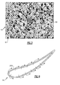
- Figure 3 shows a micrograph of a representative cross-section of the nanocellular foam 68.
- the nanocellular foam 68 includes an interconnected network of ligaments 80 between which interconnected pores 82 extend.
- the nanocellular foam 68 has an open porosity through which the pressurized cooling fluid can travel from the passage 66 to the second surface 64b.
- the path provided by the pores 82 is circuitous and narrow such that there is a relatively large pressure drop across the nanocellular foam 68.
- the pressure drop and circuitous path slow the velocity of the pressurized cooling fluid such that the nanocellular foam 68 emits the cooling fluid at the second surface 64b with a low design discharge velocity.
- the nanocellular foam 68 can be formed of a metallic material, polymeric material, a ceramic material, or combinations thereof.
- the selected composition can depend on article design factors, such as but not limited to, temperature resistance and strength.
- the metallic material can be selected from nickel, tantalum, tungsten, rhenium, niobium, hafnium, platinum, ruthenium, rhodium, palladium, osmium, iridium, copper, iron, molybdenum, yttrium, manganese, aluminum, chromium, cobalt, and combinations thereof.
- the ceramic material can be selected from oxides, nitrides, carbides, borides, silicides, and combinations thereof.
- the ceramic material can be a ternary ceramic (a MAX phase material).
- the M in the formula can be selected from Sc, Ti, Zr, Hf, V, Nb, Ta, Cr, Mo, and combinations thereof, and the A in the formula can be selected from Cd, Al, Gd, In, Tl, Si, Ge, Sn, Pb, P, As, S, and combinations thereof.
- the MAX phase material can be selected from: Ti 2 CdC, Sc 2 InC, Ti 2 AlC, Ti 2 GaC, Ti 2 InC, Ti 2 TlC, V 2 AlC, V 2 GaC, Cr 2 GaC, Ti 2 AlN, Ti 2 GaN, Ti 2 InN, V 2 GaN, Cr 2 GaN, Ti 2 GeC, Ti 2 SnC, Ti 2 PbC, V 2 GeC, Cr 2 Alc, Cr 2 GeC, V 2 PC, V 2 AsC, Ti 2 SC, Zr 2 InC, Zr 2 TlC, Nb 2 AlC, Nb 2 GaC, Nb 2 InC, Mo 2 GaC, Zr 2 InN, Zr 2 TlN, Hf 2 InC, Hf 2 TlC, Ta 2 AlC, Ta 2 GaC, Ti 2 GeC, Ti 2 SnC, Ti 2 PbC, V 2 GeC, Cr 2 AlC, Cr 2 GeC, Zr 2 SnC, Zr 2 PbC, Nb 2 SnC, Zr
- the ceramic material can include at least one of manganese oxide (MnO 2 ), zinc oxide (ZnO), silicon carbide (SiC), silicon nitride (Si 3 N 4 ) or alumina (Al 2 O 3 ).
- Examples of polymer materials can include polyamide 66, polyesters, polycarbonates, and polyimide. The disclosed metallic and ceramic materials have relatively high temperature resistance and can, thus, withstand high temperature environments, such as those encountered in the gas turbine engine 20.
- the controlled pore characteristics of the nanocellular foam 68 can include one or more of a controlled average pore size, controlled hydraulic diameter, percent porosity, surface area and controlled pore volume that are selected with respect to the design discharge velocity of the pressurized cooling fluid from the nanocellular foam 68 and the design boundary flow condition based on the boundary layer 72.
- the nanocellular foam 68 has an average pore size of 10 micrometers to 100 nanometers, and in further examples less than 1 micrometer.
- the nanocellular foam 68 has a controlled porosity of 5-95%, and in a further example has a porosity of 10-50%.
- the nanocellular foam has a controlled pore volume of 0.01-0.1 milliliters per gram.
- FIG 4 illustrates another example transpiration-cooled article, which in this example is a transpiration-cooled airfoil 160 (hereafter "airfoil 160").
- Figure 5 shows a cross-section taken along the section line shown in Figure 4 .
- like reference numerals designate like elements where appropriate and reference numerals with the addition of one-hundred or multiples thereof designate modified elements that are understood to incorporate the same features and benefits of the corresponding elements.
- the airfoil 160 includes an airfoil body 160a that has an inner surface 164a and an outer, gas-path surface 164b.
- the airfoil body includes an internal passage 166 and, similar to the article 60, at least a portion of the airfoil body 160a includes nanocellular foam 168 through which cooling fluid from the internal passage 166 can flow to the gas-path surface 164b.
- the geometry of the internal passage 166 and the location of the nanocellular foam 168 are not limited to that shown.
- the article can be an article as disclosed in U.S. Patent No. 7,144,220 , incorporated in its entirety herein by reference, and the nanocellular foam can be located according to the location of the reticulated regions disclosed therein.
- the nanocellular foam of the present disclosure can be fabricated using sol-gel processing or nanowire processing, but is not limited to these techniques.
- the sol is a mixture of precursor materials in a solvent.
- the sol can contain dispersed metal-containing compounds, a monomer and a solvent that is a non-aqueous and polar.
- the sol is then converted to a gel when the precursor materials react.
- the metal-containing compounds react with the monomer to form metal containing regions bound by polymer ligands.
- the metal from the salt initiates a reaction to polymerize the polymer precursor and agglomerate metal-intermediates into metal-containing regions bond together by the polymeric ligands.
- the metal from the salt will later form the metal ligaments of the nanocellular foam 68, 168.
- the solvent is then removed from the gel using supercritical drying to produce a dry gel of the metal-containing regions bond together by the polymeric ligands.
- the dry gel is then thermally converted to a metal cellular structure by thermal consolidation or sintering of the metal-containing regions, which also decomposes the polymer ligands.
- One or more stages of heat treatment can also be conducted in an oxygen-containing environment, such as air, a substantially oxygen-free environment, or a combination thereof to control or alter composition.
- Nanowire processing involves forming an arrangement of loose nanowires into the shape of an article using a deposition technique or mold.
- the nanowires are then bonded into a unitary structure.
- the nanowires can be sintered together using a suitable technique to form an article.
- the surfaces of the nanowires that are in contact with each other permanently bond together.
- the loose nanowires thus serve as the fundamental "building blocks" for fabricating the article.
- the airfoil 160 includes an airfoil portion 182 that extends between a leading end 182a and a trailing end 182b and a first sidewall 182c and a second sidewall 182d that is spaced apart from the first sidewall 182c.
- the sidewalls 182c/182d join the leading end 182a and the trailing end 182b.
- the internal passage 166 is defined, at least in part, by the first and second sidewalls 182c/182d, which also correspond to the gas-path surface 164b.
- the airfoil portion 182 extends from a platform end wall 184.
- the platform end wall 184 is on a radially inner end of the airfoil portion 182, relative to the orientation of the airfoil 160 with respect to the longitudinal axis A when the airfoil 160 is mounted in the engine 20.
- the airfoil 160 also includes an outer platform end wall 186, although the airfoil 160 is not limited to the design shown, which is a static vane.
- the airfoil 160 can alternatively have a different design or can be a rotatable blade, such as, but not limited to, a fan blade, a compressor blade, or a turbine blade.
- the nanocellular foam 168 can be on the airfoil portion 182, the platform end walls 184/186, or both of these areas.
- the nanocellular foam 168 is provided in multiple, discrete windows that are each surrounded by solid walls 188 of the airfoil 160. Although plural windows of equivalent geometry are shown, fewer or additional windows could be used, and the windows may have equivalent or different geometries from each other.
- the cooling fluid in the internal passage 166 can only exit from the internal passage 166 through the nanocellular foam 168 windows, as shown at 190 in Figure 5 .
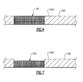
- Figure 6 shows an isolated view of an area through one of the nanocellular foam 168 windows.
- the nanocellular foam 168 is flush with the gas-path surface 164b.
- the nanocellular foam 168 window is recessed at least from the gas-path surface 164b. The recessing of the nanocellular foam 168 window further facilitates leaking the cooling fluid across the gas-path surface 164b with a desired design discharge velocity below a given threshold, discussed above.
- the above examples of the pore characteristics and composition can also be incorporated into the article 160.
- Figure 8 shows another example transpiration-cooled airfoil 260.
- a substantial portion of the wall of the airfoil is nanocellular foam 268.
- at least 50% or more of the area of the wall of the airfoil 260 can be formed of the nanocellular foam 268, to facilitate cooling over a greater surface area.
Landscapes
- Chemical & Material Sciences (AREA)
- Engineering & Computer Science (AREA)
- Ceramic Engineering (AREA)
- Materials Engineering (AREA)
- Structural Engineering (AREA)
- Organic Chemistry (AREA)
- Manufacturing & Machinery (AREA)
- Mechanical Engineering (AREA)
- General Engineering & Computer Science (AREA)
- Nanotechnology (AREA)
- Turbine Rotor Nozzle Sealing (AREA)
Abstract
Description
- This disclosure relates to cooled structures. Structures that operate in relatively high-temperature environments can be cooled by providing a cooling fluid over the outer surfaces. For example, in a gas turbine engine, airfoils include machined holes for film cooling using relatively cool air from the compressor. Film cooling is effective on the pressure side of an airfoil; yet, it is not possible on the suction side. The suction side has a high degree of boundary layer mixing causing a significant decrease in cooling effectiveness.
- A transpiration-cooled airfoil according to an example of the present disclosure includes an airfoil body that has an internal passage and an outer gas-path surface. At least a portion of the airfoil body includes a nanocellular foam through which cooling fluid from the internal passage can flow to the gas-path surface.
- In an embodiment of the foregoing embodiment, the airfoil body includes at least one discrete window of the nanocellular foam surrounded by solid walls.
- In a further embodiment of any of the foregoing embodiments, the nanocellular foam has an average pore size of 10 micrometers to 100 nanometers.
- In a further embodiment of any of the foregoing embodiments, the nanocellular foam has a porosity of 5-95%.
- In a further embodiment of any of the foregoing embodiments, the nanocellular foam has a pore volume of 0.01-0.1 milliliters per gram.
- In a further embodiment of any of the foregoing embodiments, the airfoil body includes a leading edge and a trailing edge and a first sidewall and a second sidewall that is spaced apart from the first sidewall. The first sidewall and the second sidewall join the leading edge and the trailing edge and at least partially define the internal passage. The nanocellular foam is located in the first sidewall. The first sidewall is a suction side of the airfoil body.
- In a further embodiment of any of the foregoing embodiments, the airfoil body includes a leading edge and a trailing edge and a first sidewall and a second sidewall that is spaced apart from the first sidewall. The first sidewall and the second sidewall join the leading edge and the trailing edge and at least partially define the internal cavity. The airfoil body extends from a platform end wall, and the nanocellular foam is in the platform end wall.
- A transpiration-cooled article according to an example of the present disclosure includes a body wall that has first and second opposed surfaces. The first surface is adjacent a passage that is configured to receive a pressurized cooling fluid. At least a portion of the body wall includes a nanocellular foam through which the pressurized cooling fluid from the passage can flow to the second surface.
- In a further embodiment of any of the foregoing embodiments, the nanocellular foam is metallic.
- In a further embodiment of any of the foregoing embodiments, the nanocellular foam is selected from the group consisting of nickel, tantalum, tungsten, rhenium, niobium, hafnium, platinum, ruthenium, rhodium, palladium, osmium, iridium, copper, iron, molybdenum, yttrium, manganese, aluminum, chromium, cobalt, and combinations thereof.
- In a further embodiment of any of the foregoing embodiments, the nanocellular foam is ceramic material.
- In an embodiment of the foregoing embodiments, the ceramic material is selected from the group consisting of oxides, nitrides, carbides, borides, silicides, and combinations thereof.
- In an embodiment of any of the foregoing embodiments, the ceramic material is a ternary ceramic.
- In an embodiment of any of the foregoing embodiments, the ceramic material is selected from the group consisting of manganese oxide, zinc oxide, silicon carbide, aluminum oxide, and combinations thereof.
- In a further embodiment of any of the foregoing embodiments, the body wall includes at least one discrete window of the nanocellular foam surrounded by solid wall.
- In a further embodiment of any of the foregoing embodiments, the nanocellular foam has an average pore size of less than 10 micrometers.
- In a further embodiment of any of the foregoing embodiments, the nanocellular foam has a porosity of 5-95%.
- In a further embodiment of any of the foregoing embodiments, the nanocellular foam has a pore volume of 0.01-0.1 milliliters per gram.
- A transpiration-cooled system according to an example of the present disclosure includes a passage configured to receive a pressurized cooling fluid, and a wall that has first and second opposed surfaces. The first surface is adjacent the passage, and the second surface is a gas-path surface that has a design boundary flow condition. At least a portion of the wall includes a nanocellular foam through which the pressurized cooling fluid from the passage can flow to the second surface. The nanocellular foam has controlled pore characteristics with respect to a design discharge velocity of the pressurized cooling fluid from the nanocellular foam and the design boundary flow condition.
- The various features and advantages of the present disclosure will become apparent to those skilled in the art from the following detailed description. The drawings that accompany the detailed description can be briefly described as follows.
-
Figure 1 illustrates an example gas turbine engine. -
Figure 2 illustrates a cross-section through a selected portion of a transpiration-cooled article. -
Figure 3 illustrates a micrograph of a representative portion of a nanocellular foam. -
Figure 4 illustrates another example transpiration-cooled article. -
Figure 5 illustrates a cross-section according to the section line shown inFigure 4 . -
Figure 6 illustrates an isolated view of a cross-section through a nanocellular foam window. -
Figure 7 illustrates an isolated view of a cross-section through another example nanocellular foam window. -
Figure 8 illustrates a cross-section through a selected portion of another example transpiration-cooled article. -
Figure 1 illustrates an examplegas turbine engine 20. Thegas turbine engine 20 disclosed herein is a two-spool turbofan that generally incorporates afan section 22, a compressor section 24, acombustor section 26 and aturbine section 28. Alternative engines might include an augmentor section (not shown) among other systems or features. Thefan section 22 drives air along a bypass flow path B in a bypass duct defined within anacelle 15, while the compressor section 24 drives air along a core flow path C for compression and communication into thecombustor section 26 then expansion through theturbine section 28. Although depicted as a two-spool turbofan gas turbine engine in the disclosed non-limiting embodiment, it is to be understood that this disclosure is not limited to two-spool turbofans and the teachings herein may be applied to other types of turbine engines, including but not limited to direct-drive engines, three-spool engines, and ground-based power turbines. - The
engine 20 includes alow speed spool 30 and a high speed spool 32 mounted for rotation about an engine central longitudinal axis A relative to an enginestatic structure 36 viaseveral bearing systems 38. It should be understood thatvarious bearing systems 38 at various locations may alternatively or additionally be provided, and the location ofbearing systems 38 may be varied as appropriate to the application. - The
low speed spool 30 includes aninner shaft 40 that interconnects a fan 42, a first (or low) pressure compressor 44 and a first (or low)pressure turbine 46. Theinner shaft 40 is connected to the fan 42 through a speed change mechanism, which in the exemplarygas turbine engine 20 is illustrated as a geared architecture 48, to drive the fan 42 at a lower speed than thelow speed spool 30. The high speed spool 32 includes anouter shaft 50 that interconnects a second (or high) pressure compressor 52 and a second (or high)pressure turbine 54. Acombustor 56 is arranged between the high pressure compressor 52 and thehigh pressure turbine 54. Amid-turbine frame 57 of the enginestatic structure 36 is arranged between thehigh pressure turbine 54 and thelow pressure turbine 46. Themid-turbine frame 57 further supports bearingsystems 38 in theturbine section 28. Theinner shaft 40 and theouter shaft 50 are concentric and rotate viabearing systems 38 about the engine central longitudinal axis A which is collinear with their longitudinal axes. - The core airflow is compressed by the low pressure compressor 44 then the high pressure compressor 52, mixed and burned with fuel in the
combustor 56, then expanded over thehigh pressure turbine 54 andlow pressure turbine 46. Themid-turbine frame 57 includesairfoils 59 which are in the core airflow path C. Theturbines low speed spool 30 and high speed spool 32 in response to the expansion. It will be appreciated that each of the positions of thefan section 22, compressor section 24,combustor section 26,turbine section 28, and fan drive gear system 48 may be varied. For example, gear system 48 may be located aft ofcombustor section 26 or even aft ofturbine section 28, andfan section 22 may be positioned forward or aft of the location of gear system 48. - The
engine 20 in one example is a high-bypass geared aircraft engine. In a further example, theengine 20 bypass ratio is greater than about six (6), with an example embodiment being greater than about ten (10). The geared architecture 48 can be an epicyclic gear train, such as a planetary gear system or other gear system, with a gear reduction ratio of greater than about 2.3, and thelow pressure turbine 46 has a pressure ratio that is greater than about five. In one disclosed embodiment, theengine 20 bypass ratio is greater than about ten (10:1), the fan diameter is significantly larger than that of the low pressure compressor 44, and thelow pressure turbine 46 has a pressure ratio that is greater than about five 5:1.Low pressure turbine 46 pressure ratio is pressure measured prior to inlet oflow pressure turbine 46 as related to the pressure at the outlet of thelow pressure turbine 46 prior to an exhaust nozzle. The above parameters are only exemplary and that the present disclosure is applicable to other gas turbine engines including direct drive turbofans. - A significant amount of thrust is provided by the bypass flow B due to the high bypass ratio. The
fan section 22 of theengine 20 is designed for a particular flight condition -- typically cruise at about 0.8 Mach and about 35,000 feet (10668 m). The flight condition of 0.8 Mach and 35,000 ft (10668 m), with the engine at its best fuel consumption - also known as "bucket cruise Thrust Specific Fuel Consumption ('TSFC')" - is the industry standard parameter of lbm of fuel being burned divided by lbf of thrust the engine produces at that minimum point. "Low fan pressure ratio" is the pressure ratio across the fan blade alone, without a Fan Exit Guide Vane ("FEGV") system. The low fan pressure ratio as disclosed herein according to one non-limiting embodiment is less than about 1.45. "Low corrected fan tip speed" is the actual fan tip speed in ft/sec divided by an industry standard temperature correction of [(Tram °R) / (518.7 °R)]0.5. The "Low corrected fan tip speed" as disclosed herein according to one non-limiting embodiment is less than about 1150 ft / second (350.5 m/s). -
Figure 2 illustrates a cross-section through a selected portion of an example transpiration-cooled article 60 (hereafter "article 60") that can be used in theturbine engine 20. Thearticle 60 can be an airfoil component, a blade outer air seal, a combustor liner, or the like that is exposed to high temperatures. Although thearticle 60 may be described with respect to use in the environment of theengine 20 or a similar machine, this disclosure is not limited to turbine engines or turbine engine components. - The
article 60 includes abody wall 62 that has first and secondopposed surfaces first surface 64a is adjacent apassage 66 that is configured to receive a pressurized cooling fluid. For example, thepassage 66 is connected with a source of pressurized cooling fluid, such as but not limited to, pressurized air from the compressor section 24. - At least a portion of the
body wall 62 includesnanocellular foam 68 through which the pressurized cooling fluid from thepassage 66 can flow to thesecond surface 64b, as represented at 70, to cool thesecond surface 64b. - The
nanocellular foam 68 has controlled pore characteristics with respect to a design discharge velocity of the pressurized coolingfluid 70 and a design boundary flow condition. For example, thesecond surface 64b of thebody wall 62 is a gas-path surface (e.g., in core flow path C). Friction between the moving gas in the gas-path and thesecond surface 64b creates a boundary layer, generally represented at 72. The gas in theboundary layer 72 moves at a slower velocity than the main flow of gas in the gas-path, represented at G. The controlled pore characteristics of thenanocellular foam 68 are selected such that, at a predefined state of operation having a given pressure of pressurized cooling fluid in thepassage 66 and known characteristics that define a design boundary flow condition of theboundary layer 72, there is a design discharge velocity of the pressurized cooling fluid that is leaked or emitted from thenanocellular foam 68. For example, the pore characteristics of thenanocellular foam 68 are selected such that the design discharge velocity is below a velocity threshold that would otherwise jet the pressurized cooling fluid through theboundary layer 72 into the main gas-path flow, where it would be lost and fail to efficiently provide cooling along thesecond surface 64b of thebody wall 62. Rather, the controlled pore characteristics of thenanocellular foam 68 provide a pressure drop between thepassage 66 and thesecond surface 64b such that the design discharge velocity is below the threshold and the pressurized cooling fluid leaks into theboundary layer 72 and across thesurface 64b rather than jetting through theboundary layer 72. In this regard, thenanocellular foam 68 can facilitate cooling of thebody wall 62. -
Figure 3 shows a micrograph of a representative cross-section of thenanocellular foam 68. As shown, thenanocellular foam 68 includes an interconnected network ofligaments 80 between whichinterconnected pores 82 extend. Thenanocellular foam 68 has an open porosity through which the pressurized cooling fluid can travel from thepassage 66 to thesecond surface 64b. The path provided by thepores 82 is circuitous and narrow such that there is a relatively large pressure drop across thenanocellular foam 68. The pressure drop and circuitous path slow the velocity of the pressurized cooling fluid such that thenanocellular foam 68 emits the cooling fluid at thesecond surface 64b with a low design discharge velocity. - The
nanocellular foam 68 can be formed of a metallic material, polymeric material, a ceramic material, or combinations thereof. The selected composition can depend on article design factors, such as but not limited to, temperature resistance and strength. The metallic material can be selected from nickel, tantalum, tungsten, rhenium, niobium, hafnium, platinum, ruthenium, rhodium, palladium, osmium, iridium, copper, iron, molybdenum, yttrium, manganese, aluminum, chromium, cobalt, and combinations thereof. The ceramic material can be selected from oxides, nitrides, carbides, borides, silicides, and combinations thereof. - In a further example, the ceramic material can be a ternary ceramic (a MAX phase material). A MAX phase material has a formula Mn+1AXn, where n=1-3, M is an early transition metal, A is an A-group element of the Periodic Table, and X includes at least one of carbon and nitrogen. In further examples, the M in the formula can be selected from Sc, Ti, Zr, Hf, V, Nb, Ta, Cr, Mo, and combinations thereof, and the A in the formula can be selected from Cd, Al, Gd, In, Tl, Si, Ge, Sn, Pb, P, As, S, and combinations thereof. The MAX phase material can be selected from: Ti2CdC, Sc2InC, Ti2AlC, Ti2GaC, Ti2InC, Ti2TlC, V2AlC, V2GaC, Cr2GaC, Ti2AlN, Ti2GaN, Ti2InN, V2GaN, Cr2GaN, Ti2GeC, Ti2SnC, Ti2PbC, V2GeC, Cr2Alc, Cr2GeC, V2PC, V2AsC, Ti2SC, Zr2InC, Zr2TlC, Nb2AlC, Nb2GaC, Nb2InC, Mo2GaC, Zr2InN, Zr2TlN, Hf2InC, Hf2TlC, Ta2AlC, Ta2GaC, Ti2GeC, Ti2SnC, Ti2PbC, V2GeC, Cr2AlC, Cr2GeC, Zr2SnC, Zr2PbC, Nb2SnC, Hf2SnC, Hf2PbC, Hf2SnN, V2PC, V2AsC, Nb2PC, Nb2AsC, Ti2SC, Zr2SC, Nb2SC, Hf2SC, Ti3AlC2, V3AlC2, Ta3AlC2, Ti3SiC2, Ti3GeC2, Ti3SnC2, Ti4AlN3, V4AlC3, Ti4GaC3, Nb4AlC3, Ta4AlC3, Ti4SiC3, Ti4GeC3, and combinations thereof, but is not limited to these examples.
- In further examples, the ceramic material can include at least one of manganese oxide (MnO2), zinc oxide (ZnO), silicon carbide (SiC), silicon nitride (Si3N4) or alumina (Al2O3). Examples of polymer materials can include
polyamide 66, polyesters, polycarbonates, and polyimide. The disclosed metallic and ceramic materials have relatively high temperature resistance and can, thus, withstand high temperature environments, such as those encountered in thegas turbine engine 20. - In further examples, the controlled pore characteristics of the
nanocellular foam 68 can include one or more of a controlled average pore size, controlled hydraulic diameter, percent porosity, surface area and controlled pore volume that are selected with respect to the design discharge velocity of the pressurized cooling fluid from thenanocellular foam 68 and the design boundary flow condition based on theboundary layer 72. For example, thenanocellular foam 68 has an average pore size of 10 micrometers to 100 nanometers, and in further examples less than 1 micrometer. In a further example, thenanocellular foam 68 has a controlled porosity of 5-95%, and in a further example has a porosity of 10-50%. In yet a further example, the nanocellular foam has a controlled pore volume of 0.01-0.1 milliliters per gram. -
Figure 4 illustrates another example transpiration-cooled article, which in this example is a transpiration-cooled airfoil 160 (hereafter "airfoil 160").Figure 5 shows a cross-section taken along the section line shown inFigure 4 . In this disclosure, like reference numerals designate like elements where appropriate and reference numerals with the addition of one-hundred or multiples thereof designate modified elements that are understood to incorporate the same features and benefits of the corresponding elements. - The
airfoil 160 includes anairfoil body 160a that has an inner surface 164a and an outer, gas-path surface 164b. The airfoil body includes aninternal passage 166 and, similar to thearticle 60, at least a portion of theairfoil body 160a includesnanocellular foam 168 through which cooling fluid from theinternal passage 166 can flow to the gas-path surface 164b. The geometry of theinternal passage 166 and the location of thenanocellular foam 168 are not limited to that shown. In further examples, although not limited, the article can be an article as disclosed inU.S. Patent No. 7,144,220 , incorporated in its entirety herein by reference, and the nanocellular foam can be located according to the location of the reticulated regions disclosed therein. The nanocellular foam of the present disclosure can be fabricated using sol-gel processing or nanowire processing, but is not limited to these techniques. - In sol-gel processing, the sol is a mixture of precursor materials in a solvent. The sol can contain dispersed metal-containing compounds, a monomer and a solvent that is a non-aqueous and polar. The sol is then converted to a gel when the precursor materials react. The metal-containing compounds react with the monomer to form metal containing regions bound by polymer ligands. The metal from the salt initiates a reaction to polymerize the polymer precursor and agglomerate metal-intermediates into metal-containing regions bond together by the polymeric ligands. The metal from the salt will later form the metal ligaments of the
nanocellular foam - Nanowire processing involves forming an arrangement of loose nanowires into the shape of an article using a deposition technique or mold. The nanowires are then bonded into a unitary structure. For example, the nanowires can be sintered together using a suitable technique to form an article. During the thermal sintering, the surfaces of the nanowires that are in contact with each other permanently bond together. The loose nanowires thus serve as the fundamental "building blocks" for fabricating the article.
- The
airfoil 160 includes anairfoil portion 182 that extends between aleading end 182a and a trailingend 182b and afirst sidewall 182c and asecond sidewall 182d that is spaced apart from thefirst sidewall 182c. Thesidewalls 182c/182d join theleading end 182a and the trailingend 182b. Theinternal passage 166 is defined, at least in part, by the first andsecond sidewalls 182c/182d, which also correspond to the gas-path surface 164b. - In this example, the
airfoil portion 182 extends from aplatform end wall 184. Theplatform end wall 184 is on a radially inner end of theairfoil portion 182, relative to the orientation of theairfoil 160 with respect to the longitudinal axis A when theairfoil 160 is mounted in theengine 20. In this example, theairfoil 160 also includes an outerplatform end wall 186, although theairfoil 160 is not limited to the design shown, which is a static vane. Theairfoil 160 can alternatively have a different design or can be a rotatable blade, such as, but not limited to, a fan blade, a compressor blade, or a turbine blade. - The
nanocellular foam 168 can be on theairfoil portion 182, theplatform end walls 184/186, or both of these areas. In this example, thenanocellular foam 168 is provided in multiple, discrete windows that are each surrounded bysolid walls 188 of theairfoil 160. Although plural windows of equivalent geometry are shown, fewer or additional windows could be used, and the windows may have equivalent or different geometries from each other. - The cooling fluid in the
internal passage 166 can only exit from theinternal passage 166 through the nanocellular foam 168 windows, as shown at 190 inFigure 5 . -
Figure 6 shows an isolated view of an area through one of thenanocellular foam 168 windows. In this example, thenanocellular foam 168 is flush with the gas-path surface 164b. In an alternate example shown inFigure 7 , thenanocellular foam 168 window is recessed at least from the gas-path surface 164b. The recessing of thenanocellular foam 168 window further facilitates leaking the cooling fluid across the gas-path surface 164b with a desired design discharge velocity below a given threshold, discussed above. As can be appreciated, the above examples of the pore characteristics and composition can also be incorporated into thearticle 160. -
Figure 8 shows another example transpiration-cooledairfoil 260. In this example, rather than one or more discrete windows of nanocellular foam, a substantial portion of the wall of the airfoil isnanocellular foam 268. For example, at least 50% or more of the area of the wall of theairfoil 260 can be formed of thenanocellular foam 268, to facilitate cooling over a greater surface area. - Although a combination of features is shown in the illustrated examples, not all of them need to be combined to realize the benefits of various embodiments of this disclosure. In other words, a system designed according to an embodiment of this disclosure will not necessarily include all of the features shown in any one of the Figures or all of the portions schematically shown in the Figures. Moreover, selected features of one example embodiment may be combined with selected features of other example embodiments.
- The preceding description is exemplary rather than limiting in nature. Variations and modifications to the disclosed examples may become apparent to those skilled in the art that do not necessarily depart from the essence of this disclosure. The scope of legal protection given to this disclosure can only be determined by studying the following claims.
Claims (15)
- A transpiration-cooled airfoil (60; 160;260) comprising:an airfoil body (160a) that includes an internal passage (166) and an outer gas-path surface (164b), andat least a portion of the airfoil body (160a) includes a nanocellular foam (68;168;268) through which cooling fluid from the internal passage (166) can flow to the gas-path surface (164b).
- The transpiration-cooled airfoil as recited in claim 1, wherein the airfoil body (160a) includes a leading edge (182a) and a trailing edge (182b) and a first sidewall (182d) and a second sidewall (182d) that is spaced apart from the first sidewall (182c), the first sidewall (182c) and the second sidewall (182d) join the leading edge (182a) and the trailing edge (182b) and at least partially define the internal passage (166), and the nanocellular foam (168) is located in the second sidewall (182d), and the second sidewall (182d) is a suction side of the airfoil body (160a).
- The transpiration-cooled airfoil as recited in claim 1 or 2, wherein the airfoil body (160a) includes a leading edge (182a) and a trailing edge (182b) and a first sidewall (182c) and a second sidewall (182d) that is spaced apart from the first sidewall (182c), the first sidewall (182c) and the second sidewall (182d) join the leading edge (182a) and the trailing edge (182b) and at least partially define the internal cavity (166), the airfoil body (160a) extending from a platform end wall (184), and the nanocellular foam (168) is in the platform end wall (164).
- A transpiration-cooled article (60;160;260) comprising:a body wall (62) having first and second opposed surfaces (64a,64b;164a,164b), the first surface (64a;164a) is adjacent a passage (66;166) that is configured to receive a pressurized cooling fluid, andat least a portion of the body wall (62) includes a nanocellular foam (68;168;268) through which the pressurized cooling fluid from the passage can flow to the second surface.
- The transpiration-cooled article or transpiration-cooled airfoil as recited in any preceding claim, wherein the airfoil body (160a) or body wall (62) includes at least one discrete window of the nanocellular foam (168) surrounded by solid wall(s).
- The transpiration-cooled article or transpiration-cooled airfoil as recited in any preceding claim, wherein the nanocellular foam has an average pore size of 10 micrometers to 100 nanometers.
- The transpiration-cooled article or transpiration-cooled airfoil as recited in any of claims 1 to 5, wherein the nanocellular foam has an average pore size of less than 10 micrometers.
- The transpiration-cooled article or transpiration-cooled airfoil as recited in any preceding claim, wherein the nanocellular foam (68;168;268) has a porosity of 5-95%.
- The transpiration-cooled article or transpiration-cooled airfoil as recited in claim 8, wherein the nanocellular foam (68;168;268) has a pore volume of 0.01-0.1 milliliters per gram.
- The transpiration-cooled article or transpiration-cooled airfoil as recited in any preceding claim, wherein the nanocellular foam (68;168;268) is metallic.
- The transpiration-cooled article or transpiration-cooled airfoil as recited in claim 10, wherein the nanocellular foam is selected from the group consisting of nickel, tantalum, tungsten, rhenium, niobium, hafnium, platinum, ruthenium, rhodium, palladium, osmium, iridium, copper, iron, molybdenum, yttrium, manganese, aluminum, chromium, cobalt, and combinations thereof.
- The transpiration-cooled article or transpiration-cooled airfoil as recited in any of claims 1 to 9, wherein the nanocellular foam (68;168;268) is ceramic material.
- The transpiration-cooled article or transpiration-cooled airfoil as recited in claim 12, wherein the ceramic material is selected from the group consisting of oxides, nitrides, carbides, borides, silicides, and combinations thereof.
- The transpiration-cooled article or transpiration-cooled airfoil as recited in claim 12, wherein the ceramic material is a ternary ceramic.
- The transpiration-cooled article or transpiration-cooled airfoil as recited in claim 12, wherein the ceramic material is selected from the group consisting of manganese oxide, zinc oxide, silicon carbide, aluminum oxide, and combinations thereof.
Applications Claiming Priority (1)
| Application Number | Priority Date | Filing Date | Title |
|---|---|---|---|
| US201462004254P | 2014-05-29 | 2014-05-29 |
Publications (2)
| Publication Number | Publication Date |
|---|---|
| EP2949634A1 true EP2949634A1 (en) | 2015-12-02 |
| EP2949634B1 EP2949634B1 (en) | 2020-03-11 |
Family
ID=53264589
Family Applications (1)
| Application Number | Title | Priority Date | Filing Date |
|---|---|---|---|
| EP15169601.0A Active EP2949634B1 (en) | 2014-05-29 | 2015-05-28 | Transpiration-cooled article having nanocellular foam |
Country Status (2)
| Country | Link |
|---|---|
| US (1) | US20150345302A1 (en) |
| EP (1) | EP2949634B1 (en) |
Cited By (3)
| Publication number | Priority date | Publication date | Assignee | Title |
|---|---|---|---|---|
| EP3249159A1 (en) * | 2016-05-23 | 2017-11-29 | Siemens Aktiengesellschaft | Turbine blade and corresponding turbomachine |
| EP3281724A1 (en) * | 2016-08-09 | 2018-02-14 | United Technologies Corporation | Carbon as an aide for ductile nanocellular foam |
| WO2018034791A1 (en) * | 2016-08-16 | 2018-02-22 | General Electric Company | Engine component with porous section |
Families Citing this family (5)
| Publication number | Priority date | Publication date | Assignee | Title |
|---|---|---|---|---|
| US10458259B2 (en) * | 2016-05-12 | 2019-10-29 | General Electric Company | Engine component wall with a cooling circuit |
| DE102017205788A1 (en) * | 2017-04-05 | 2018-10-11 | Siemens Aktiengesellschaft | Hot gas component for a gas turbine |
| KR102230700B1 (en) * | 2017-09-12 | 2021-03-23 | 한국기계연구원 | Gas turbin blade |
| KR102158298B1 (en) * | 2019-02-21 | 2020-09-21 | 두산중공업 주식회사 | Turbine blade, turbine including the same |
| CN110696440B (en) * | 2019-10-08 | 2020-12-18 | 西安电子科技大学 | Excessive thermal protection flexible skin for high-speed aircraft based on porous foam and its method |
Citations (3)
| Publication number | Priority date | Publication date | Assignee | Title |
|---|---|---|---|---|
| US5690473A (en) * | 1992-08-25 | 1997-11-25 | General Electric Company | Turbine blade having transpiration strip cooling and method of manufacture |
| US6443700B1 (en) * | 2000-11-08 | 2002-09-03 | General Electric Co. | Transpiration-cooled structure and method for its preparation |
| US7144220B2 (en) | 2004-07-30 | 2006-12-05 | United Technologies Corporation | Investment casting |
Family Cites Families (15)
| Publication number | Priority date | Publication date | Assignee | Title |
|---|---|---|---|---|
| DE2414641A1 (en) * | 1974-03-26 | 1975-10-16 | Kernforschung Gmbh Ges Fuer | CORROSION RESISTANT TURBINE BLADES AND METHOD OF MANUFACTURING THEREOF |
| GB2042648B (en) * | 1979-02-24 | 1983-05-05 | Rolls Royce | Gas turbine engine hollow blades |
| EP1465836A2 (en) * | 2001-12-21 | 2004-10-13 | Battelle Memorial Institute | Structures containing carbon nanotubes and a porous support, methods of making the same, and related uses |
| US6713519B2 (en) * | 2001-12-21 | 2004-03-30 | Battelle Memorial Institute | Carbon nanotube-containing catalysts, methods of making, and reactions catalyzed over nanotube catalysts |
| US20050111966A1 (en) * | 2003-11-26 | 2005-05-26 | Metheny Alfred P. | Construction of static structures for gas turbine engines |
| US8828540B2 (en) * | 2006-06-16 | 2014-09-09 | United Technologies Corporation | Silicon carbide ceramic containing materials, their methods of manufacture and articles comprising the same |
| US7838108B2 (en) * | 2007-01-17 | 2010-11-23 | Sabic Innovative Plastics Ip B.V. | Nano-cellular polymer foam and methods for making them |
| US20110117338A1 (en) * | 2008-04-29 | 2011-05-19 | Ben Poquette | Open pore ceramic matrix coated with metal or metal alloys and methods of making same |
| US20100055492A1 (en) * | 2008-06-03 | 2010-03-04 | Drexel University | Max-based metal matrix composites |
| US8052378B2 (en) * | 2009-03-18 | 2011-11-08 | General Electric Company | Film-cooling augmentation device and turbine airfoil incorporating the same |
| US8529808B2 (en) * | 2010-05-21 | 2013-09-10 | Basf Se | Nanoporous polymer foams |
| US20130340981A1 (en) * | 2012-01-09 | 2013-12-26 | Tessera, Inc. | Electrohydrodynamic (ehd) air mover configuration with flow path expansion and/or spreading for improved ozone catalysis |
| CA2874043C (en) * | 2012-05-24 | 2021-09-14 | Siluria Technologies, Inc. | Catalytic forms and formulations |
| US20140044951A1 (en) * | 2012-08-09 | 2014-02-13 | United Technologies Corporation | High strength-to-density nanocellular foam |
| EP3071800B1 (en) * | 2013-10-23 | 2019-11-27 | United Technologies Corporation | Nanocellular foam damper |
-
2015
- 2015-05-07 US US14/706,045 patent/US20150345302A1/en not_active Abandoned
- 2015-05-28 EP EP15169601.0A patent/EP2949634B1/en active Active
Patent Citations (3)
| Publication number | Priority date | Publication date | Assignee | Title |
|---|---|---|---|---|
| US5690473A (en) * | 1992-08-25 | 1997-11-25 | General Electric Company | Turbine blade having transpiration strip cooling and method of manufacture |
| US6443700B1 (en) * | 2000-11-08 | 2002-09-03 | General Electric Co. | Transpiration-cooled structure and method for its preparation |
| US7144220B2 (en) | 2004-07-30 | 2006-12-05 | United Technologies Corporation | Investment casting |
Cited By (5)
| Publication number | Priority date | Publication date | Assignee | Title |
|---|---|---|---|---|
| EP3249159A1 (en) * | 2016-05-23 | 2017-11-29 | Siemens Aktiengesellschaft | Turbine blade and corresponding turbomachine |
| EP3281724A1 (en) * | 2016-08-09 | 2018-02-14 | United Technologies Corporation | Carbon as an aide for ductile nanocellular foam |
| US10478894B2 (en) | 2016-08-09 | 2019-11-19 | United Technologies Corporation | Carbon as an aide for ductile nanocellular foam |
| WO2018034791A1 (en) * | 2016-08-16 | 2018-02-22 | General Electric Company | Engine component with porous section |
| US10612389B2 (en) | 2016-08-16 | 2020-04-07 | General Electric Company | Engine component with porous section |
Also Published As
| Publication number | Publication date |
|---|---|
| EP2949634B1 (en) | 2020-03-11 |
| US20150345302A1 (en) | 2015-12-03 |
Similar Documents
| Publication | Publication Date | Title |
|---|---|---|
| EP2949634B1 (en) | Transpiration-cooled article having nanocellular foam | |
| EP3027853B1 (en) | Gas turbine engine cmc airfoil assembly | |
| EP3342980B1 (en) | Airfoil with dual profile leading end | |
| EP3080401B1 (en) | Bonded multi-piece gas turbine engine component | |
| EP2959115B1 (en) | Abradable seal including an abradability characteristic that varies by locality | |
| EP3323984B1 (en) | Airfoil with geometrically segmented coating section | |
| EP3323985B1 (en) | Airfoil, gas turbine engine article, corresponding gas turbine engine and method of assembling an airfoil | |
| EP2942488B1 (en) | Blade for a gas turbine engine, gas turbine engine and method of cooling a blade for a gas turbine engine | |
| EP3323991B1 (en) | Vane or blade with airfoil piece having radial seal | |
| EP3047119A2 (en) | Cooling configuration for engine component | |
| EP3351729B1 (en) | Gas turbine engine component and corresponding gas turbine engine | |
| EP3339571A1 (en) | Airfoil with panel having flow guide | |
| EP3133251A1 (en) | Blade outer air seal component with varying thermal expansion coefficient | |
| EP3071800B1 (en) | Nanocellular foam damper | |
| EP3323979B1 (en) | Airfoil with panel having perimeter seal | |
| US11319817B2 (en) | Airfoil with panel and side edge cooling | |
| EP3324000A1 (en) | Airfoil and corresponding gas turbine engine and airfoil article | |
| EP3045666A1 (en) | Airfoil platform with cooling feed orifices | |
| EP3323986B1 (en) | Airfoil with geometrically segmented coating section | |
| EP3323993A1 (en) | Airfoil with airfoil piece having axial seal | |
| EP4379192A1 (en) | Seal slot with coating | |
| EP3323996B1 (en) | Turbine engine component with geometrically segmented coating section and cooling passage | |
| EP3708784B1 (en) | Blade outer air seal assembly with cooling supply | |
| EP3556998B1 (en) | Air seal having gaspath portion with geometrically segmented coating | |
| EP3324004B1 (en) | Airfoil with retention pocket holding airfoil piece |
Legal Events
| Date | Code | Title | Description |
|---|---|---|---|
| AK | Designated contracting states |
Kind code of ref document: A1 Designated state(s): AL AT BE BG CH CY CZ DE DK EE ES FI FR GB GR HR HU IE IS IT LI LT LU LV MC MK MT NL NO PL PT RO RS SE SI SK SM TR |
|
| AX | Request for extension of the european patent |
Extension state: BA ME |
|
| PUAI | Public reference made under article 153(3) epc to a published international application that has entered the european phase |
Free format text: ORIGINAL CODE: 0009012 |
|
| 17P | Request for examination filed |
Effective date: 20160601 |
|
| RBV | Designated contracting states (corrected) |
Designated state(s): AL AT BE BG CH CY CZ DE DK EE ES FI FR GB GR HR HU IE IS IT LI LT LU LV MC MK MT NL NO PL PT RO RS SE SI SK SM TR |
|
| RAP1 | Party data changed (applicant data changed or rights of an application transferred) |
Owner name: UNITED TECHNOLOGIES CORPORATION |
|
| STAA | Information on the status of an ep patent application or granted ep patent |
Free format text: STATUS: REQUEST FOR EXAMINATION WAS MADE |
|
| R17P | Request for examination filed (corrected) |
Effective date: 20160601 |
|
| STAA | Information on the status of an ep patent application or granted ep patent |
Free format text: STATUS: EXAMINATION IS IN PROGRESS |
|
| 17Q | First examination report despatched |
Effective date: 20180711 |
|
| GRAP | Despatch of communication of intention to grant a patent |
Free format text: ORIGINAL CODE: EPIDOSNIGR1 |
|
| STAA | Information on the status of an ep patent application or granted ep patent |
Free format text: STATUS: GRANT OF PATENT IS INTENDED |
|
| INTG | Intention to grant announced |
Effective date: 20191011 |
|
| GRAS | Grant fee paid |
Free format text: ORIGINAL CODE: EPIDOSNIGR3 |
|
| GRAA | (expected) grant |
Free format text: ORIGINAL CODE: 0009210 |
|
| STAA | Information on the status of an ep patent application or granted ep patent |
Free format text: STATUS: THE PATENT HAS BEEN GRANTED |
|
| AK | Designated contracting states |
Kind code of ref document: B1 Designated state(s): AL AT BE BG CH CY CZ DE DK EE ES FI FR GB GR HR HU IE IS IT LI LT LU LV MC MK MT NL NO PL PT RO RS SE SI SK SM TR |
|
| REG | Reference to a national code |
Ref country code: GB Ref legal event code: FG4D |
|
| REG | Reference to a national code |
Ref country code: CH Ref legal event code: EP |
|
| REG | Reference to a national code |
Ref country code: AT Ref legal event code: REF Ref document number: 1242965 Country of ref document: AT Kind code of ref document: T Effective date: 20200315 |
|
| REG | Reference to a national code |
Ref country code: DE Ref legal event code: R096 Ref document number: 602015048450 Country of ref document: DE |
|
| REG | Reference to a national code |
Ref country code: IE Ref legal event code: FG4D |
|
| PG25 | Lapsed in a contracting state [announced via postgrant information from national office to epo] |
Ref country code: NO Free format text: LAPSE BECAUSE OF FAILURE TO SUBMIT A TRANSLATION OF THE DESCRIPTION OR TO PAY THE FEE WITHIN THE PRESCRIBED TIME-LIMIT Effective date: 20200611 Ref country code: FI Free format text: LAPSE BECAUSE OF FAILURE TO SUBMIT A TRANSLATION OF THE DESCRIPTION OR TO PAY THE FEE WITHIN THE PRESCRIBED TIME-LIMIT Effective date: 20200311 Ref country code: RS Free format text: LAPSE BECAUSE OF FAILURE TO SUBMIT A TRANSLATION OF THE DESCRIPTION OR TO PAY THE FEE WITHIN THE PRESCRIBED TIME-LIMIT Effective date: 20200311 |
|
| REG | Reference to a national code |
Ref country code: NL Ref legal event code: MP Effective date: 20200311 |
|
| PG25 | Lapsed in a contracting state [announced via postgrant information from national office to epo] |
Ref country code: HR Free format text: LAPSE BECAUSE OF FAILURE TO SUBMIT A TRANSLATION OF THE DESCRIPTION OR TO PAY THE FEE WITHIN THE PRESCRIBED TIME-LIMIT Effective date: 20200311 Ref country code: GR Free format text: LAPSE BECAUSE OF FAILURE TO SUBMIT A TRANSLATION OF THE DESCRIPTION OR TO PAY THE FEE WITHIN THE PRESCRIBED TIME-LIMIT Effective date: 20200612 Ref country code: LV Free format text: LAPSE BECAUSE OF FAILURE TO SUBMIT A TRANSLATION OF THE DESCRIPTION OR TO PAY THE FEE WITHIN THE PRESCRIBED TIME-LIMIT Effective date: 20200311 Ref country code: BG Free format text: LAPSE BECAUSE OF FAILURE TO SUBMIT A TRANSLATION OF THE DESCRIPTION OR TO PAY THE FEE WITHIN THE PRESCRIBED TIME-LIMIT Effective date: 20200611 Ref country code: SE Free format text: LAPSE BECAUSE OF FAILURE TO SUBMIT A TRANSLATION OF THE DESCRIPTION OR TO PAY THE FEE WITHIN THE PRESCRIBED TIME-LIMIT Effective date: 20200311 |
|
| REG | Reference to a national code |
Ref country code: LT Ref legal event code: MG4D |
|
| PG25 | Lapsed in a contracting state [announced via postgrant information from national office to epo] |
Ref country code: NL Free format text: LAPSE BECAUSE OF FAILURE TO SUBMIT A TRANSLATION OF THE DESCRIPTION OR TO PAY THE FEE WITHIN THE PRESCRIBED TIME-LIMIT Effective date: 20200311 |
|
| PG25 | Lapsed in a contracting state [announced via postgrant information from national office to epo] |
Ref country code: CZ Free format text: LAPSE BECAUSE OF FAILURE TO SUBMIT A TRANSLATION OF THE DESCRIPTION OR TO PAY THE FEE WITHIN THE PRESCRIBED TIME-LIMIT Effective date: 20200311 Ref country code: IS Free format text: LAPSE BECAUSE OF FAILURE TO SUBMIT A TRANSLATION OF THE DESCRIPTION OR TO PAY THE FEE WITHIN THE PRESCRIBED TIME-LIMIT Effective date: 20200711 Ref country code: RO Free format text: LAPSE BECAUSE OF FAILURE TO SUBMIT A TRANSLATION OF THE DESCRIPTION OR TO PAY THE FEE WITHIN THE PRESCRIBED TIME-LIMIT Effective date: 20200311 Ref country code: SM Free format text: LAPSE BECAUSE OF FAILURE TO SUBMIT A TRANSLATION OF THE DESCRIPTION OR TO PAY THE FEE WITHIN THE PRESCRIBED TIME-LIMIT Effective date: 20200311 Ref country code: EE Free format text: LAPSE BECAUSE OF FAILURE TO SUBMIT A TRANSLATION OF THE DESCRIPTION OR TO PAY THE FEE WITHIN THE PRESCRIBED TIME-LIMIT Effective date: 20200311 Ref country code: LT Free format text: LAPSE BECAUSE OF FAILURE TO SUBMIT A TRANSLATION OF THE DESCRIPTION OR TO PAY THE FEE WITHIN THE PRESCRIBED TIME-LIMIT Effective date: 20200311 Ref country code: SK Free format text: LAPSE BECAUSE OF FAILURE TO SUBMIT A TRANSLATION OF THE DESCRIPTION OR TO PAY THE FEE WITHIN THE PRESCRIBED TIME-LIMIT Effective date: 20200311 Ref country code: PT Free format text: LAPSE BECAUSE OF FAILURE TO SUBMIT A TRANSLATION OF THE DESCRIPTION OR TO PAY THE FEE WITHIN THE PRESCRIBED TIME-LIMIT Effective date: 20200805 |
|
| REG | Reference to a national code |
Ref country code: AT Ref legal event code: MK05 Ref document number: 1242965 Country of ref document: AT Kind code of ref document: T Effective date: 20200311 |
|
| REG | Reference to a national code |
Ref country code: DE Ref legal event code: R097 Ref document number: 602015048450 Country of ref document: DE |
|
| PLBE | No opposition filed within time limit |
Free format text: ORIGINAL CODE: 0009261 |
|
| STAA | Information on the status of an ep patent application or granted ep patent |
Free format text: STATUS: NO OPPOSITION FILED WITHIN TIME LIMIT |
|
| PG25 | Lapsed in a contracting state [announced via postgrant information from national office to epo] |
Ref country code: LI Free format text: LAPSE BECAUSE OF NON-PAYMENT OF DUE FEES Effective date: 20200531 Ref country code: AT Free format text: LAPSE BECAUSE OF FAILURE TO SUBMIT A TRANSLATION OF THE DESCRIPTION OR TO PAY THE FEE WITHIN THE PRESCRIBED TIME-LIMIT Effective date: 20200311 Ref country code: DK Free format text: LAPSE BECAUSE OF FAILURE TO SUBMIT A TRANSLATION OF THE DESCRIPTION OR TO PAY THE FEE WITHIN THE PRESCRIBED TIME-LIMIT Effective date: 20200311 Ref country code: CH Free format text: LAPSE BECAUSE OF NON-PAYMENT OF DUE FEES Effective date: 20200531 Ref country code: ES Free format text: LAPSE BECAUSE OF FAILURE TO SUBMIT A TRANSLATION OF THE DESCRIPTION OR TO PAY THE FEE WITHIN THE PRESCRIBED TIME-LIMIT Effective date: 20200311 Ref country code: IT Free format text: LAPSE BECAUSE OF FAILURE TO SUBMIT A TRANSLATION OF THE DESCRIPTION OR TO PAY THE FEE WITHIN THE PRESCRIBED TIME-LIMIT Effective date: 20200311 Ref country code: MC Free format text: LAPSE BECAUSE OF FAILURE TO SUBMIT A TRANSLATION OF THE DESCRIPTION OR TO PAY THE FEE WITHIN THE PRESCRIBED TIME-LIMIT Effective date: 20200311 |
|
| 26N | No opposition filed |
Effective date: 20201214 |
|
| PG25 | Lapsed in a contracting state [announced via postgrant information from national office to epo] |
Ref country code: PL Free format text: LAPSE BECAUSE OF FAILURE TO SUBMIT A TRANSLATION OF THE DESCRIPTION OR TO PAY THE FEE WITHIN THE PRESCRIBED TIME-LIMIT Effective date: 20200311 Ref country code: SI Free format text: LAPSE BECAUSE OF FAILURE TO SUBMIT A TRANSLATION OF THE DESCRIPTION OR TO PAY THE FEE WITHIN THE PRESCRIBED TIME-LIMIT Effective date: 20200311 |
|
| REG | Reference to a national code |
Ref country code: BE Ref legal event code: MM Effective date: 20200531 |
|
| PG25 | Lapsed in a contracting state [announced via postgrant information from national office to epo] |
Ref country code: LU Free format text: LAPSE BECAUSE OF NON-PAYMENT OF DUE FEES Effective date: 20200528 |
|
| PG25 | Lapsed in a contracting state [announced via postgrant information from national office to epo] |
Ref country code: IE Free format text: LAPSE BECAUSE OF NON-PAYMENT OF DUE FEES Effective date: 20200528 |
|
| PG25 | Lapsed in a contracting state [announced via postgrant information from national office to epo] |
Ref country code: BE Free format text: LAPSE BECAUSE OF NON-PAYMENT OF DUE FEES Effective date: 20200531 |
|
| PG25 | Lapsed in a contracting state [announced via postgrant information from national office to epo] |
Ref country code: TR Free format text: LAPSE BECAUSE OF FAILURE TO SUBMIT A TRANSLATION OF THE DESCRIPTION OR TO PAY THE FEE WITHIN THE PRESCRIBED TIME-LIMIT Effective date: 20200311 Ref country code: MT Free format text: LAPSE BECAUSE OF FAILURE TO SUBMIT A TRANSLATION OF THE DESCRIPTION OR TO PAY THE FEE WITHIN THE PRESCRIBED TIME-LIMIT Effective date: 20200311 Ref country code: CY Free format text: LAPSE BECAUSE OF FAILURE TO SUBMIT A TRANSLATION OF THE DESCRIPTION OR TO PAY THE FEE WITHIN THE PRESCRIBED TIME-LIMIT Effective date: 20200311 |
|
| PG25 | Lapsed in a contracting state [announced via postgrant information from national office to epo] |
Ref country code: MK Free format text: LAPSE BECAUSE OF FAILURE TO SUBMIT A TRANSLATION OF THE DESCRIPTION OR TO PAY THE FEE WITHIN THE PRESCRIBED TIME-LIMIT Effective date: 20200311 Ref country code: AL Free format text: LAPSE BECAUSE OF FAILURE TO SUBMIT A TRANSLATION OF THE DESCRIPTION OR TO PAY THE FEE WITHIN THE PRESCRIBED TIME-LIMIT Effective date: 20200311 |
|
| REG | Reference to a national code |
Ref country code: DE Ref legal event code: R081 Ref document number: 602015048450 Country of ref document: DE Owner name: RAYTHEON TECHNOLOGIES CORPORATION (N.D.GES.D.S, US Free format text: FORMER OWNER: UNITED TECHNOLOGIES CORPORATION, FARMINGTON, CONN., US Ref country code: DE Ref legal event code: R081 Ref document number: 602015048450 Country of ref document: DE Owner name: RTX CORPORATION (N.D.GES.D. STAATES DELAWARE),, US Free format text: FORMER OWNER: UNITED TECHNOLOGIES CORPORATION, FARMINGTON, CONN., US |
|
| P01 | Opt-out of the competence of the unified patent court (upc) registered |
Effective date: 20230520 |
|
| PGFP | Annual fee paid to national office [announced via postgrant information from national office to epo] |
Ref country code: DE Payment date: 20250423 Year of fee payment: 11 |
|
| PGFP | Annual fee paid to national office [announced via postgrant information from national office to epo] |
Ref country code: GB Payment date: 20250423 Year of fee payment: 11 |
|
| PGFP | Annual fee paid to national office [announced via postgrant information from national office to epo] |
Ref country code: FR Payment date: 20250423 Year of fee payment: 11 |
|
| REG | Reference to a national code |
Ref country code: DE Ref legal event code: R081 Ref document number: 602015048450 Country of ref document: DE Owner name: RTX CORPORATION (N.D.GES.D. STAATES DELAWARE),, US Free format text: FORMER OWNER: RAYTHEON TECHNOLOGIES CORPORATION (N.D.GES.D.STAATES DELAWARE), ARLINGTON, VA, US |