EP2949601A1 - Elastic dispenser of bag-in-bottle type - Google Patents
Elastic dispenser of bag-in-bottle type Download PDFInfo
- Publication number
- EP2949601A1 EP2949601A1 EP14170231.6A EP14170231A EP2949601A1 EP 2949601 A1 EP2949601 A1 EP 2949601A1 EP 14170231 A EP14170231 A EP 14170231A EP 2949601 A1 EP2949601 A1 EP 2949601A1
- Authority
- EP
- European Patent Office
- Prior art keywords
- bag
- product
- dispenser
- container
- dispensing
- Prior art date
- Legal status (The legal status is an assumption and is not a legal conclusion. Google has not performed a legal analysis and makes no representation as to the accuracy of the status listed.)
- Granted
Links
Images





Classifications
-
- B—PERFORMING OPERATIONS; TRANSPORTING
- B65—CONVEYING; PACKING; STORING; HANDLING THIN OR FILAMENTARY MATERIAL
- B65D—CONTAINERS FOR STORAGE OR TRANSPORT OF ARTICLES OR MATERIALS, e.g. BAGS, BARRELS, BOTTLES, BOXES, CANS, CARTONS, CRATES, DRUMS, JARS, TANKS, HOPPERS, FORWARDING CONTAINERS; ACCESSORIES, CLOSURES, OR FITTINGS THEREFOR; PACKAGING ELEMENTS; PACKAGES
- B65D83/00—Containers or packages with special means for dispensing contents
- B65D83/771—Containers or packages with special means for dispensing contents for dispensing fluent contents by means of a flexible bag or a deformable membrane or diaphragm
-
- A—HUMAN NECESSITIES
- A45—HAND OR TRAVELLING ARTICLES
- A45D—HAIRDRESSING OR SHAVING EQUIPMENT; EQUIPMENT FOR COSMETICS OR COSMETIC TREATMENTS, e.g. FOR MANICURING OR PEDICURING
- A45D19/00—Devices for washing the hair or the scalp; Similar devices for colouring the hair
- A45D19/02—Hand-actuated implements, e.g. hand-actuated spray heads
- A45D19/022—Hand-actuated implements, e.g. hand-actuated spray heads for applying simultaneously two or more substances, e.g. colouring agents, to the hair without prior mixing
-
- A—HUMAN NECESSITIES
- A45—HAND OR TRAVELLING ARTICLES
- A45D—HAIRDRESSING OR SHAVING EQUIPMENT; EQUIPMENT FOR COSMETICS OR COSMETIC TREATMENTS, e.g. FOR MANICURING OR PEDICURING
- A45D34/00—Containers or accessories specially adapted for handling liquid toiletry or cosmetic substances, e.g. perfumes
- A45D34/04—Appliances specially adapted for applying liquid, e.g. using roller or ball
- A45D34/042—Appliances specially adapted for applying liquid, e.g. using roller or ball using a brush or the like
-
- A—HUMAN NECESSITIES
- A45—HAND OR TRAVELLING ARTICLES
- A45D—HAIRDRESSING OR SHAVING EQUIPMENT; EQUIPMENT FOR COSMETICS OR COSMETIC TREATMENTS, e.g. FOR MANICURING OR PEDICURING
- A45D40/00—Casings or accessories specially adapted for storing or handling solid or pasty toiletry or cosmetic substances, e.g. shaving soaps or lipsticks
- A45D40/24—Casings for two or more cosmetics
-
- B—PERFORMING OPERATIONS; TRANSPORTING
- B65—CONVEYING; PACKING; STORING; HANDLING THIN OR FILAMENTARY MATERIAL
- B65D—CONTAINERS FOR STORAGE OR TRANSPORT OF ARTICLES OR MATERIALS, e.g. BAGS, BARRELS, BOTTLES, BOXES, CANS, CARTONS, CRATES, DRUMS, JARS, TANKS, HOPPERS, FORWARDING CONTAINERS; ACCESSORIES, CLOSURES, OR FITTINGS THEREFOR; PACKAGING ELEMENTS; PACKAGES
- B65D81/00—Containers, packaging elements, or packages, for contents presenting particular transport or storage problems, or adapted to be used for non-packaging purposes after removal of contents
- B65D81/32—Containers, packaging elements, or packages, for contents presenting particular transport or storage problems, or adapted to be used for non-packaging purposes after removal of contents for packaging two or more different materials which must be maintained separate prior to use in admixture
- B65D81/3233—Flexible containers disposed within rigid containers
- B65D81/3244—Flexible containers disposed within rigid containers arranged parallel or concentrically and permitting simultaneous dispensing of the two materials without prior mixing
-
- A—HUMAN NECESSITIES
- A45—HAND OR TRAVELLING ARTICLES
- A45D—HAIRDRESSING OR SHAVING EQUIPMENT; EQUIPMENT FOR COSMETICS OR COSMETIC TREATMENTS, e.g. FOR MANICURING OR PEDICURING
- A45D2200/00—Details not otherwise provided for in A45D
- A45D2200/05—Details of containers
- A45D2200/054—Means for supplying liquid to the outlet of the container
- A45D2200/056—Reciprocating pumps, i.e. with variable volume chamber wherein pressure and vacuum are alternately generated
Definitions
- the present invention relates to a dispenser comprising at least one inner flexible bag containing a dispensable product and an associated valve.
- DE 39 23 903 A1 discloses a dispenser of bag-in-bottle type comprising an inner bag, wherein the inner bag has a bottom fold extending in a direction away from the bag.
- DE 41 21 179 A1 discloses a dispenser of bag-in-bottle type comprising an inner bag, wherein the inner bag has a fold towards the upper end of the bag.
- DE 2 103 447 B1 discloses a dispenser of bag-in-bottle type comprising an inner bag, wherein the inner bag has flat lateral areas.
- the use of the so called bag-in-bottle-type technology is a known technology, wherein an inner bag is disposed within a bottle or can of a dispenser.
- the bag comprises a valve at an upper end through which a stored product may be expelled.
- the bottle or can is usually made of an elastic material such as plastics. If the bottle or can is pressed, the inner bag is pressed as well and the stored product is expelled through the valve.
- the bag-in-bottle-type technology is a technology for increasing the dispensable amount of the product stored within the bag because the bag may be compressed to a considerable degree. As the product stored in the inner bag may be expensive, e.g. cosmetic or medical products, there is a desire to further increase the dispensable amount of the content of a container using the bag-in-bottle technology.
- a dispenser according to the present invention increases the dispensable amount so a to decrease waste of stored product.
- Fig. 1 shows a dispenser 10 according to a first embodiment of the present invention.
- the dispenser 10 comprises an outer elastic container 12, an inner flexible bag 14 and a valve assembly 16 through which the product may be expelled or dispensed from the flexible bag 14. Further, the dispenser 10 may comprise a dispenser cap 18 as shown in Fig. 1 . Particularly, the dispenser 10 may be used for storing and dispensing hairstyling/coloring products.
- the inner flexible bag 14 containing a dispensable product, e.g. a chemical product, a cosmetic product or a medical product.
- the flexible bag 14 may be made of a thermoplastic material such as polyethylene.
- the material of the bag 14 is preferably a soft material having a shore hardness smaller than 95.
- the flexible bag 14 is located within the outer elastic container 12 so that there is space 20 left between the flexible bag 14 and the container 12. More particularly, the space 20 exists between an inner wall 22 of the container 12 and an outer wall 24 of the flexible bag 14.
- the flexible bag 14 is attached to a upper brim 26 of the container 12.
- Figs. 3 and 4 show cross-sectional views of the bag 14 taken along a longitudinal axis of the bag and shifted with an angle of 90 ° with respect to each other.
- the flexible bag 14 can be made from a single material or from a composite material, which preferably comprises at least a polymeric layer and a layer which acts as a gas barrier, e.g., made from metal, such as aluminum.
- the inner material of the flexible bag 14 is inert to the contents of the product stored therein, and more preferably the inner material is also impenetrable by the contents of the product in the flexible bag 14.
- the flexible bag comprises a layer of a material which is essentially impermeable to a gas such as ambient air outside of the bag and within the space 20, which generally may not intended to be mixed with the product in the flexible bag 14 during storage.
- a gas such as ambient air outside of the bag and within the space 20, which generally may not intended to be mixed with the product in the flexible bag 14 during storage.
- Mixing of the product in the flexible bag 14 and the gas outside of the flexible bag 14 can be inappropriate to the properties of for example a cosmetic composition in the flexible bag 14 during storage, e.g., due to the fact that the gas outside of the flexible bag 14 influences the properties of the cosmetic composition during storage in a negative way.
- the flexile bag 14 comprises flat lateral edges 28 as shown in Fig. 1 and is additionally arranged so as to comprise a bottom fold 30 directed towards an upper end 32 of the flexible bag 14 in order to allow a controlled collapse of the bag 14.
- a collapsed or folded stat is shown in Fig. 5 .
- the bag 14 can comprise two flat triangular portions 34 forming the bottom fold 30 each extending from its bottom edge 36 to its lateral edge 28 so as to form an angle of about 90° between the portions 34. This can further facilitate the collapse of the flexible bag 14 when compressed as shown in Fig. 5 .
- the flexible bag 14 comprises at the upper end 32 thereof an opening 38 enclosed by a brim 40.
- the brim 40 comprises air guiding channels 42 which extend from an radial outer portion 44 to a position 46 on a lower side 48 of the brim 40 which is located radially inwards with respect to the radial outer portion 44.
- the opening may comprise a diameter of about 17 mm and the brim 40 may comprise a diameter of about 24 mm.
- the upper side 50 of the brim 40 may serve as a sealing surface as will be explained below.
- the valve assembly 16 consists of a lower portion 52 shown in Fig. 7B and an upper portion 54 shown in Fig. 7C .
- the valve assembly 16 may be shaped as a disk or circular plate.
- the lower portion 52 of the valve assembly 16 comprises a central opening 56, which may be circular, and two venting holes 58, which may be rectangular.
- the upper portion 54 may be a cover for the lower portion 52 and is adapted to be mounted to the lower portion 52.
- the upper portion 54 comprises a central plate shaped flap 60 or baffle adapted to close or open the central opening 56 of the lower portion 52 and two venting flaps 62 adapted to close or open the venting holes 58 of the lower portion 52.
- the flap 60 and the flaps 62 may be two-way valve.
- the flap 60 and the flaps 62 may be pivotably mounted or hinged to the upper portion 54
- the flexible bag 14 and the valve assembly 16 are attached to the upper brim 26 of the container 12 such that an upper end 64 of the container 12 engages the lower side 48 of the brim 40 of the bag 14 in a gas tight manner and the valve assembly 16 engages the upper side 50 of the brim 40 of the bag 14 and the container 12 in a gas tight manner, wherein an annular space 66 is left between the valve assembly 16 and the container 12. Accordingly, the interior of the flexible bag 14 and the space 20 between the container 12 and the flexible bag 14 are each independently sealed.
- gas from within the space 20 is vented from the space 20 between the outer container 12 and the bag 14 in that the air flows through the air guiding channels 42 within the brim 40 of the bag 14, enters the space 66 and passes through the venting holes 58 as the flaps 62 are pivoted upwards as indicated by arrows 70 in Fig. 8 . If the pressure is released the outer container 12 returns to the original form due to its wall rigidity and the flap 60 of the valve assembly 16 closes the central opening 56. Further, ambient air may pass the venting holes 58 and flow into the space 66 between the outer container 12 and the valve assembly 16 as the flaps 62 are pivoted downwards as indicated by arrows 72.
- the air may further flow through the air guiding channels 42 within the brim 40 of the bag 14 and enter the space 20 between the outer container 12 and the bag 14. Accordingly, the venting holes 58 allow ambient air to enter and exit the space 20 between the container 12 and the flexible bag 14. Thus, the venting holes 58 and the space 20 communicate by means of he air guiding channels 42. As no air enters the flexible bag 14, the flexible bag 14 is continuously pressed together according to the number of pressing operations. Thereby, the product may be dispensed from throughout the bag 14 including product remaining at the bottom of the bag 14.
- the dispensable amount of a product stored within the bag 14 may be increased by the combination of the arrangement of the bag 14 so as to comprise a bottom fold 30, the provision of the valve assembly 16 at the upper end 24 of the bag 14 and the flat lateral edges 28 of the bag 14. Even product remaining at the bottom of the bag 14 may be dispensed because the bottom fold 30 allows the bag 14 to be compressed in a manner that the triangular portions 32 cause the product to escape therefrom.
- the dispensable amount may be further increased if the container 12 comprises two flat areas 74, which may be gripped by a human hand and facilitates to apply the pressing force onto the container 12 and the bag 14.
- Each flat area 74 may be provided so as to be aligned in the circumferential direction with respect to the flat lateral edges 28 of the bag 14, which further facilitates the collapsing of the bag 14.
- Fig. 9 shows a dispenser 10 of a second embodiment of the present invention. It is to be appreciated that only the differences from the dispenser of the first embodiment will be described and like numerals are intended to indicate like constructional members.
- the dispenser 10 comprises two inner flexible bags 14 each containing a dispensable product, which may be adapted to complement each other.
- the bags may be arranged within the container 12 so as to comprise a bottom fold 30 which is directed towards a lower end 76 of the bags 14.
- Figs. 11A to 11 C show the valve assembly 16 of the dispenser 10 of the second embodiment.
- the upper portion 54 includes two flaps 60 adapted to close the opening 56.
- the flaps 60 may be hinged at a bar 78 extend along a direction of the diameter of the opening 56.
- the operation of the dispenser 10 according to the second embodiment is almost identical to the operation of the dispenser of the first embodiment as shown in Fig. 12 such that a detailed description of the operation is omitted.
- the dispenser 10 of the second embodiment allows to simultaneously dispense two products each stored within a bag 14. Further, if the container is pressed and the pressure exceeds a threshold determined by the characteristics of the flaps 60, both flaps 60 pivot in an upward direction as indicated by arrows 70.
Landscapes
- Engineering & Computer Science (AREA)
- Mechanical Engineering (AREA)
- Containers And Packaging Bodies Having A Special Means To Remove Contents (AREA)
- Packages (AREA)
Abstract
Description
- The present invention relates to a dispenser comprising at least one inner flexible bag containing a dispensable product and an associated valve.
-
DE 39 23 903 A1 discloses a dispenser of bag-in-bottle type comprising an inner bag, wherein the inner bag has a bottom fold extending in a direction away from the bag. -
DE 41 21 179 A1 discloses a dispenser of bag-in-bottle type comprising an inner bag, wherein the inner bag has a fold towards the upper end of the bag. -
DE 2 103 447 B1 - The use of the so called bag-in-bottle-type technology is a known technology, wherein an inner bag is disposed within a bottle or can of a dispenser. The bag comprises a valve at an upper end through which a stored product may be expelled. The bottle or can is usually made of an elastic material such as plastics. If the bottle or can is pressed, the inner bag is pressed as well and the stored product is expelled through the valve. The bag-in-bottle-type technology is a technology for increasing the dispensable amount of the product stored within the bag because the bag may be compressed to a considerable degree. As the product stored in the inner bag may be expensive, e.g. cosmetic or medical products, there is a desire to further increase the dispensable amount of the content of a container using the bag-in-bottle technology.
- Therefore, it is an object of the present invention to provide a dispenser allowing to further increase the dispensable amount of a product stored in a bag of a container using the bag-in-bottle technology.
- This object is achieved by a dispenser according to the present invention. Particularly, the dispenser increases the dispensable amount so a to decrease waste of stored product.
- These and other advantages and features of the various embodiments of the invention disclosed herein, will be made more apparent from the description, drawings and claims that follow. Summarizing the ideas of the present invention, the following items are preferred:
- Item 1: A dispenser for dispensing a product of the present invention, particularly for dispensing a cosmetic product, comprises a container comprising a brim, at least one bag for storing the product, wherein the bag is located within the container and has an upper end attached to the brim, and is provided with a valve assembly adapted to selectively allow the product to be dispensed or prevent the product to be dispensed, wherein the bag further comprises flat lateral edges and is arranged so as to comprise a bottom fold.
- Item 2: The dispenser of item 1, wherein the bag may be located within the container such that a space between the container and the bag is left, wherein the valve assembly comprises at least one venting hole adapted to allow a gas within the space to be vented from the space if a pressing force is applied to the container and to allow a gas to enter the space if the pressing force is released.
- Item 3: The dispenser of
item 2, wherein the valve assembly may comprise at least one pivotal flap selectively blocking or opening the venting hole. - Item 4: The dispenser of
item 2, wherein the bag may comprise a brim, wherein the brim includes air guiding channels adapted to communicate the venting hole and the space. - Item 5: The dispenser of item 1, wherein the valve assembly may comprise a central opening through which the product is dispensable and a pivotal flap selectively blocking or opening the opening.
- Item 6:The dispenser of item 1, wherein the bottom fold may be directed towards the upper end or the lower end of the bag.
- Item 7: The dispenser of item 1, wherein the bag may comprise two flat triangular portions forming the bottom fold each extending from its bottom edge to its lateral edge so as to form an angle of about 90° between the portions.
- Item 8: The dispenser of item 1, wherein the container may comprise two flat areas.
- Item 9: The dispenser of item 1, wherein The dispenser may further comprise two bags for storing the product, wherein the bags are arranged so as to form the bottom fold.
- Item 10: The dispenser of item 6, wherein the valve assembly may comprise two pivotal flaps.
-
-
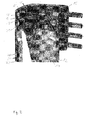
Fig. 1 is a schematic explosion view of a dispenser of a first embodiment of the present invention. -
Fig. 2 is a schematic partly cross-sectional view of the dispenser ofFig. 1 . -
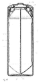
Fig. 3 is a schematic cross-sectional view of a bag of the dispenser ofFig. 1 . -
Fig. 4 is another schematic cross-sectional view of a bag of the dispenser ofFig. 1 . -
Fig. 5 is a schematic cross-sectional view of a bag of the dispenser ofFig. 1 in a folded state. -
Fig. 6 is an enlarged view of an upper end of the bag. -
Fig 7A is a schematic cross-sectional view of a valve assembly of the dispenser ofFig. 1 . -
Fig. 7B is a schematic plan view of a lower portion of the valve assembly. -
Fig. 7C is a schematic plan view of an upper portion of the valve assembly. -
Fig. 8 is a schematic view of the operational principle of the valve assembly. -
Fig. 9 is a schematic explosion view of a dispenser of a second embodiment of the present invention. -
Fig. 10 is a schematic cross-sectional view of the dispenser ofFig. 9 . -
Fig 11A is a schematic cross-sectional view of a valve assembly of the dispenser ofFig. 9 . -
Fig. 11B is a schematic plan view of a lower portion of the valve assembly. -
Fig. 11C is a schematic plan view of an upper portion of the valve assembly. -
Fig. 12 is a schematic view of the operational principle of the valve assembly. -
Fig. 1 shows adispenser 10 according to a first embodiment of the present invention. Thedispenser 10 comprises an outerelastic container 12, an innerflexible bag 14 and avalve assembly 16 through which the product may be expelled or dispensed from theflexible bag 14. Further, thedispenser 10 may comprise adispenser cap 18 as shown inFig. 1 . Particularly, thedispenser 10 may be used for storing and dispensing hairstyling/coloring products. The innerflexible bag 14 containing a dispensable product, e.g. a chemical product, a cosmetic product or a medical product. Theflexible bag 14 may be made of a thermoplastic material such as polyethylene. The material of thebag 14 is preferably a soft material having a shore hardness smaller than 95. - As shown in
Fig. 2 , which shows a partly cross-sectional view of thedispenser 10, theflexible bag 14 is located within the outerelastic container 12 so that there isspace 20 left between theflexible bag 14 and thecontainer 12. More particularly, thespace 20 exists between aninner wall 22 of thecontainer 12 and an outer wall 24 of theflexible bag 14. Theflexible bag 14 is attached to aupper brim 26 of thecontainer 12. -
Figs. 3 and4 show cross-sectional views of thebag 14 taken along a longitudinal axis of the bag and shifted with an angle of 90 ° with respect to each other. Now, there will be discussed some particularly relevant details of theflexible bag 14. Theflexible bag 14 can be made from a single material or from a composite material, which preferably comprises at least a polymeric layer and a layer which acts as a gas barrier, e.g., made from metal, such as aluminum. Preferably the inner material of theflexible bag 14 is inert to the contents of the product stored therein, and more preferably the inner material is also impenetrable by the contents of the product in theflexible bag 14. It is further preferred if the flexible bag comprises a layer of a material which is essentially impermeable to a gas such as ambient air outside of the bag and within thespace 20, which generally may not intended to be mixed with the product in theflexible bag 14 during storage. Mixing of the product in theflexible bag 14 and the gas outside of theflexible bag 14 can be inappropriate to the properties of for example a cosmetic composition in theflexible bag 14 during storage, e.g., due to the fact that the gas outside of theflexible bag 14 influences the properties of the cosmetic composition during storage in a negative way. - This does, however, not preclude the possibility that the product inside of the
flexible bag 14 and the gas outside of theflexible bag 14 are mixed upon dispensing of the cosmetic composition when thevalve assembly 16 is triggered to open and to dispense the content of theflexible bag 14. A mixing channel or another appropriate measure can be used in such a case to mix the gas outside of theflexible bag 14 with the dispensed cosmetic composition, if this is desired. - The
flexile bag 14 comprises flatlateral edges 28 as shown inFig. 1 and is additionally arranged so as to comprise abottom fold 30 directed towards anupper end 32 of theflexible bag 14 in order to allow a controlled collapse of thebag 14. Such a collapsed or folded stat is shown inFig. 5 . In the area of thebottom fold 30, thebag 14 can comprise two flattriangular portions 34 forming thebottom fold 30 each extending from itsbottom edge 36 to itslateral edge 28 so as to form an angle of about 90° between theportions 34. This can further facilitate the collapse of theflexible bag 14 when compressed as shown inFig. 5 . - As shown in
Fig. 6 , Theflexible bag 14 comprises at theupper end 32 thereof anopening 38 enclosed by abrim 40. Thebrim 40 comprises air guiding channels 42 which extend from an radialouter portion 44 to aposition 46 on alower side 48 of thebrim 40 which is located radially inwards with respect to the radialouter portion 44. For example, the opening may comprise a diameter of about 17 mm and thebrim 40 may comprise a diameter of about 24 mm. Theupper side 50 of thebrim 40 may serve as a sealing surface as will be explained below. - As shown in
Figs. 7A to 7C , thevalve assembly 16 consists of alower portion 52 shown inFig. 7B and anupper portion 54 shown inFig. 7C . Generally, all types of valves can be part of thevalve assembly 16. For example, thevalve assembly 16 may be shaped as a disk or circular plate. Thelower portion 52 of thevalve assembly 16 comprises a central opening 56, which may be circular, and two ventingholes 58, which may be rectangular. Theupper portion 54 may be a cover for thelower portion 52 and is adapted to be mounted to thelower portion 52. Theupper portion 54 comprises a central plate shapedflap 60 or baffle adapted to close or open the central opening 56 of thelower portion 52 and two ventingflaps 62 adapted to close or open the venting holes 58 of thelower portion 52. Theflap 60 and theflaps 62 may be two-way valve. Theflap 60 and theflaps 62 may be pivotably mounted or hinged to theupper portion 54 - As shown in
Fig. 2 and8 , theflexible bag 14 and thevalve assembly 16 are attached to theupper brim 26 of thecontainer 12 such that anupper end 64 of thecontainer 12 engages thelower side 48 of thebrim 40 of thebag 14 in a gas tight manner and thevalve assembly 16 engages theupper side 50 of thebrim 40 of thebag 14 and thecontainer 12 in a gas tight manner, wherein anannular space 66 is left between thevalve assembly 16 and thecontainer 12. Accordingly, the interior of theflexible bag 14 and thespace 20 between thecontainer 12 and theflexible bag 14 are each independently sealed. - The operational principle of the dispenser will be explained with reference to the above mentioned drawings and particularly with reference to
Fig. 8 . If thecontainer 12 is pressed, the flexibleinner bag 14 is pressed as well because thecontainer 12 transmits the pressing force to thebag 14. If the pressure acting on theouter container 12 and thebag 14 exceeds a threshold, which is determined by the characteristics of theflap 60 of thevalve assembly 16, theflap 60 is pivoted in an upward direction as indicated by an arrow 68 inFig. 8 such that the central opening 56 is no longer blocked and is opened. Thus, the contents of thebag 14 is dispensed through theopening 38 of thebag 14 and the central opening 56 of thevalve assembly 16. Further, gas from within thespace 20 is vented from thespace 20 between theouter container 12 and thebag 14 in that the air flows through the air guiding channels 42 within thebrim 40 of thebag 14, enters thespace 66 and passes through the venting holes 58 as theflaps 62 are pivoted upwards as indicated byarrows 70 inFig. 8 . If the pressure is released theouter container 12 returns to the original form due to its wall rigidity and theflap 60 of thevalve assembly 16 closes the central opening 56. Further, ambient air may pass the venting holes 58 and flow into thespace 66 between theouter container 12 and thevalve assembly 16 as theflaps 62 are pivoted downwards as indicated byarrows 72. The air may further flow through the air guiding channels 42 within thebrim 40 of thebag 14 and enter thespace 20 between theouter container 12 and thebag 14. Accordingly, the venting holes 58 allow ambient air to enter and exit thespace 20 between thecontainer 12 and theflexible bag 14. Thus, the venting holes 58 and thespace 20 communicate by means of he air guiding channels 42. As no air enters theflexible bag 14, theflexible bag 14 is continuously pressed together according to the number of pressing operations. Thereby, the product may be dispensed from throughout thebag 14 including product remaining at the bottom of thebag 14. As can be taken from the above, the dispensable amount of a product stored within thebag 14 may be increased by the combination of the arrangement of thebag 14 so as to comprise abottom fold 30, the provision of thevalve assembly 16 at the upper end 24 of thebag 14 and the flat lateral edges 28 of thebag 14. Even product remaining at the bottom of thebag 14 may be dispensed because thebottom fold 30 allows thebag 14 to be compressed in a manner that thetriangular portions 32 cause the product to escape therefrom. The dispensable amount may be further increased if thecontainer 12 comprises two flat areas 74, which may be gripped by a human hand and facilitates to apply the pressing force onto thecontainer 12 and thebag 14. Each flat area 74 may be provided so as to be aligned in the circumferential direction with respect to the flat lateral edges 28 of thebag 14, which further facilitates the collapsing of thebag 14. -
Fig. 9 shows adispenser 10 of a second embodiment of the present invention. It is to be appreciated that only the differences from the dispenser of the first embodiment will be described and like numerals are intended to indicate like constructional members. - According to the
dispenser 10 of the second embodiment, thedispenser 10 comprises two innerflexible bags 14 each containing a dispensable product, which may be adapted to complement each other. As shown inFig. 10 , the bags may be arranged within thecontainer 12 so as to comprise abottom fold 30 which is directed towards alower end 76 of thebags 14.Figs. 11A to 11 C show thevalve assembly 16 of thedispenser 10 of the second embodiment. Theupper portion 54 includes twoflaps 60 adapted to close the opening 56. Theflaps 60 may be hinged at abar 78 extend along a direction of the diameter of the opening 56. - The operation of the
dispenser 10 according to the second embodiment is almost identical to the operation of the dispenser of the first embodiment as shown inFig. 12 such that a detailed description of the operation is omitted. The only difference is that thedispenser 10 of the second embodiment allows to simultaneously dispense two products each stored within abag 14. Further, if the container is pressed and the pressure exceeds a threshold determined by the characteristics of theflaps 60, bothflaps 60 pivot in an upward direction as indicated byarrows 70. - The dimensions and values disclosed herein are not to be understood as being strictly limited to the exact numerical values recited. Instead, unless otherwise specified, each such dimension is intended to mean both the recited value and a functionally equivalent range surrounding that value. For example, a dimension disclosed as "40 mm" is intended to mean "about 40 mm."
Claims (10)
- Dispenser (10) for dispensing a product, particularly a cosmetic product, comprising a container (12) comprising a brim (26),
at least one bag (14) for storing the product, wherein the bag (14) is located within the container (12) and has an upper end (32) attached to the brim (26),
a valve assembly (16) adapted to selectively allow the product to be dispensed or prevent the product to be dispensed, wherein the bag (14) further comprises flat lateral edges (28) and is arranged so as to comprise a bottom fold (30). - Dispenser (10) for dispensing a product of claim 1, wherein the bag (14) is located within the container (12) such that a space (20) between the container (12) and the bag (14) is left, wherein the valve assembly (16) comprises at least one venting hole (58) adapted to allow a gas within the space (20) to be vented from the space (26) if a pressing force is applied to the container (12) and to allow a gas to enter the space (20) if the pressing force is released.
- Dispenser (10) for dispensing a product of claim 2, wherein the valve assembly (16) comprises at least one pivotal flap (62) selectively blocking or opening the venting hole (58).
- Dispenser (10) for dispensing a product of claim 2, wherein the bag (14) comprises a brim (40), wherein the brim (40) includes air guiding channels (42) adapted to communicate the venting hole (58) and the space (20).
- Dispenser (10) for dispensing a product of claim 1, wherein the valve assembly (16) comprises a central opening (56) through which the product is dispensable and a pivotal flap (60) selectively blocking or opening the opening (56)
- Dispenser (10) for dispensing a product of claim 1, wherein the bottom fold (30) is directed towards the upper end (32) or the lower end (76) of the bag (14).
- Dispenser (10) for dispensing a product of claim 1, wherein the bag (14) comprises two flat triangular portions (34) forming the bottom fold (30) each extending from its bottom edge (36) to its lateral edge (28) so as to form an angle of about 90° between the portions (34).
- Dispenser (10) for dispensing a product of claim 1, wherein the container (12) comprises two flat areas (74).
- Dispenser (10) for dispensing a product of claim 1, comprising two bags (14) for storing the product, wherein the bags (14) are arranged so as to form the bottom fold (30).
- Dispenser (10) for dispensing a product of claim 6, wherein the valve assembly (16) comprises two pivotal flaps (60).
Priority Applications (1)
| Application Number | Priority Date | Filing Date | Title |
|---|---|---|---|
| EP14170231.6A EP2949601B1 (en) | 2014-05-28 | 2014-05-28 | Elastic dispenser of bag-in-bottle type |
Applications Claiming Priority (1)
| Application Number | Priority Date | Filing Date | Title |
|---|---|---|---|
| EP14170231.6A EP2949601B1 (en) | 2014-05-28 | 2014-05-28 | Elastic dispenser of bag-in-bottle type |
Publications (2)
| Publication Number | Publication Date |
|---|---|
| EP2949601A1 true EP2949601A1 (en) | 2015-12-02 |
| EP2949601B1 EP2949601B1 (en) | 2016-10-05 |
Family
ID=50927916
Family Applications (1)
| Application Number | Title | Priority Date | Filing Date |
|---|---|---|---|
| EP14170231.6A Not-in-force EP2949601B1 (en) | 2014-05-28 | 2014-05-28 | Elastic dispenser of bag-in-bottle type |
Country Status (1)
| Country | Link |
|---|---|
| EP (1) | EP2949601B1 (en) |
Cited By (1)
| Publication number | Priority date | Publication date | Assignee | Title |
|---|---|---|---|---|
| US20210085056A1 (en) * | 2019-04-14 | 2021-03-25 | Toly Management Ltd. | Cosmetic applicator with facial application member and pump |
Citations (4)
| Publication number | Priority date | Publication date | Assignee | Title |
|---|---|---|---|---|
| DE2103447B1 (en) | 1971-01-26 | 1972-08-17 | Presspack Co., Schaffhausen (Schweiz) | Can for receiving and dispensing liquid masses under pressure |
| DE3923903A1 (en) | 1989-07-19 | 1991-01-24 | Hirsch Anton | METHOD FOR FILLING COMPRESSED GAS PACKS AND COMPRESSED GAS PACKING |
| DE4121179A1 (en) | 1991-06-27 | 1993-03-11 | Kautex Werke Gmbh | CRUSH BOTTLE WITH INNER CONTAINER |
| US20130292421A1 (en) * | 2012-05-01 | 2013-11-07 | Ming-Lang CHUANG | Cosmetic container |
-
2014
- 2014-05-28 EP EP14170231.6A patent/EP2949601B1/en not_active Not-in-force
Patent Citations (4)
| Publication number | Priority date | Publication date | Assignee | Title |
|---|---|---|---|---|
| DE2103447B1 (en) | 1971-01-26 | 1972-08-17 | Presspack Co., Schaffhausen (Schweiz) | Can for receiving and dispensing liquid masses under pressure |
| DE3923903A1 (en) | 1989-07-19 | 1991-01-24 | Hirsch Anton | METHOD FOR FILLING COMPRESSED GAS PACKS AND COMPRESSED GAS PACKING |
| DE4121179A1 (en) | 1991-06-27 | 1993-03-11 | Kautex Werke Gmbh | CRUSH BOTTLE WITH INNER CONTAINER |
| US20130292421A1 (en) * | 2012-05-01 | 2013-11-07 | Ming-Lang CHUANG | Cosmetic container |
Cited By (1)
| Publication number | Priority date | Publication date | Assignee | Title |
|---|---|---|---|---|
| US20210085056A1 (en) * | 2019-04-14 | 2021-03-25 | Toly Management Ltd. | Cosmetic applicator with facial application member and pump |
Also Published As
| Publication number | Publication date |
|---|---|
| EP2949601B1 (en) | 2016-10-05 |
Similar Documents
| Publication | Publication Date | Title |
|---|---|---|
| US8757452B2 (en) | Dispenser assembly | |
| FI87173B (en) | FOERPACKNING FOER LAGRING OCH UTMATNING AV FLUIDER. | |
| US10696534B2 (en) | Liquid dispenser | |
| EP2655208B2 (en) | Infant formula container | |
| US5108007A (en) | Valve controlled squeezable fluid dispenser | |
| KR101406056B1 (en) | Container lid having a pressure equalizing device | |
| EP2356033B1 (en) | Dispensing container | |
| EP2605980B1 (en) | High flow aerosol valve | |
| US10266315B2 (en) | Upright dispenser | |
| EP0046754B1 (en) | Combined piercer and valve for flexible bag | |
| US20090084814A1 (en) | Closure with liner piercing movable spout | |
| US20140294324A1 (en) | Storage Apparatus With A Breachable Flow Conduit For Discharging A Fluid Stored Therein | |
| US9254944B1 (en) | Assembly and method for pouring liquid from a container | |
| JPH0648455A (en) | System consisting of container with slit valve as vent valve and liquid contained in the container | |
| IL97444A (en) | Squeezable dispenser apparatus | |
| PL202388B1 (en) | Dosing assembly | |
| JP2010534598A (en) | Container insert for zero headspace | |
| EP2949601B1 (en) | Elastic dispenser of bag-in-bottle type | |
| US20190151874A1 (en) | Valve for an end piece including a shut-off device | |
| EP3275800B1 (en) | Valve having a protective cage | |
| US4750647A (en) | Non-aerosol dispenser | |
| US4938393A (en) | Bimodal storage and dispensing package for fluent material | |
| JP6100183B2 (en) | Liquid leak prevention cap for double containers | |
| US20140291357A1 (en) | Dispenser with sanitary discharge | |
| KR101319796B1 (en) | Inserts for multiple component containers |
Legal Events
| Date | Code | Title | Description |
|---|---|---|---|
| AK | Designated contracting states |
Kind code of ref document: A1 Designated state(s): AL AT BE BG CH CY CZ DE DK EE ES FI FR GB GR HR HU IE IS IT LI LT LU LV MC MK MT NL NO PL PT RO RS SE SI SK SM TR |
|
| AX | Request for extension of the european patent |
Extension state: BA ME |
|
| PUAI | Public reference made under article 153(3) epc to a published international application that has entered the european phase |
Free format text: ORIGINAL CODE: 0009012 |
|
| 17P | Request for examination filed |
Effective date: 20160112 |
|
| GRAP | Despatch of communication of intention to grant a patent |
Free format text: ORIGINAL CODE: EPIDOSNIGR1 |
|
| INTG | Intention to grant announced |
Effective date: 20160426 |
|
| GRAS | Grant fee paid |
Free format text: ORIGINAL CODE: EPIDOSNIGR3 |
|
| GRAA | (expected) grant |
Free format text: ORIGINAL CODE: 0009210 |
|
| AK | Designated contracting states |
Kind code of ref document: B1 Designated state(s): AL AT BE BG CH CY CZ DE DK EE ES FI FR GB GR HR HU IE IS IT LI LT LU LV MC MK MT NL NO PL PT RO RS SE SI SK SM TR |
|
| REG | Reference to a national code |
Ref country code: GB Ref legal event code: FG4D |
|
| REG | Reference to a national code |
Ref country code: CH Ref legal event code: EP |
|
| REG | Reference to a national code |
Ref country code: AT Ref legal event code: REF Ref document number: 834420 Country of ref document: AT Kind code of ref document: T Effective date: 20161015 |
|
| REG | Reference to a national code |
Ref country code: IE Ref legal event code: FG4D |
|
| REG | Reference to a national code |
Ref country code: DE Ref legal event code: R096 Ref document number: 602014004040 Country of ref document: DE |
|
| REG | Reference to a national code |
Ref country code: NL Ref legal event code: MP Effective date: 20161005 |
|
| REG | Reference to a national code |
Ref country code: LT Ref legal event code: MG4D |
|
| PG25 | Lapsed in a contracting state [announced via postgrant information from national office to epo] |
Ref country code: LV Free format text: LAPSE BECAUSE OF FAILURE TO SUBMIT A TRANSLATION OF THE DESCRIPTION OR TO PAY THE FEE WITHIN THE PRESCRIBED TIME-LIMIT Effective date: 20161005 |
|
| REG | Reference to a national code |
Ref country code: AT Ref legal event code: MK05 Ref document number: 834420 Country of ref document: AT Kind code of ref document: T Effective date: 20161005 |
|
| PG25 | Lapsed in a contracting state [announced via postgrant information from national office to epo] |
Ref country code: SE Free format text: LAPSE BECAUSE OF FAILURE TO SUBMIT A TRANSLATION OF THE DESCRIPTION OR TO PAY THE FEE WITHIN THE PRESCRIBED TIME-LIMIT Effective date: 20161005 Ref country code: NO Free format text: LAPSE BECAUSE OF FAILURE TO SUBMIT A TRANSLATION OF THE DESCRIPTION OR TO PAY THE FEE WITHIN THE PRESCRIBED TIME-LIMIT Effective date: 20170105 Ref country code: LT Free format text: LAPSE BECAUSE OF FAILURE TO SUBMIT A TRANSLATION OF THE DESCRIPTION OR TO PAY THE FEE WITHIN THE PRESCRIBED TIME-LIMIT Effective date: 20161005 Ref country code: GR Free format text: LAPSE BECAUSE OF FAILURE TO SUBMIT A TRANSLATION OF THE DESCRIPTION OR TO PAY THE FEE WITHIN THE PRESCRIBED TIME-LIMIT Effective date: 20170106 |
|
| PG25 | Lapsed in a contracting state [announced via postgrant information from national office to epo] |
Ref country code: ES Free format text: LAPSE BECAUSE OF FAILURE TO SUBMIT A TRANSLATION OF THE DESCRIPTION OR TO PAY THE FEE WITHIN THE PRESCRIBED TIME-LIMIT Effective date: 20161005 Ref country code: RS Free format text: LAPSE BECAUSE OF FAILURE TO SUBMIT A TRANSLATION OF THE DESCRIPTION OR TO PAY THE FEE WITHIN THE PRESCRIBED TIME-LIMIT Effective date: 20161005 Ref country code: HR Free format text: LAPSE BECAUSE OF FAILURE TO SUBMIT A TRANSLATION OF THE DESCRIPTION OR TO PAY THE FEE WITHIN THE PRESCRIBED TIME-LIMIT Effective date: 20161005 Ref country code: PT Free format text: LAPSE BECAUSE OF FAILURE TO SUBMIT A TRANSLATION OF THE DESCRIPTION OR TO PAY THE FEE WITHIN THE PRESCRIBED TIME-LIMIT Effective date: 20170206 Ref country code: IS Free format text: LAPSE BECAUSE OF FAILURE TO SUBMIT A TRANSLATION OF THE DESCRIPTION OR TO PAY THE FEE WITHIN THE PRESCRIBED TIME-LIMIT Effective date: 20170205 Ref country code: NL Free format text: LAPSE BECAUSE OF FAILURE TO SUBMIT A TRANSLATION OF THE DESCRIPTION OR TO PAY THE FEE WITHIN THE PRESCRIBED TIME-LIMIT Effective date: 20161005 Ref country code: BE Free format text: LAPSE BECAUSE OF FAILURE TO SUBMIT A TRANSLATION OF THE DESCRIPTION OR TO PAY THE FEE WITHIN THE PRESCRIBED TIME-LIMIT Effective date: 20161005 Ref country code: FI Free format text: LAPSE BECAUSE OF FAILURE TO SUBMIT A TRANSLATION OF THE DESCRIPTION OR TO PAY THE FEE WITHIN THE PRESCRIBED TIME-LIMIT Effective date: 20161005 Ref country code: PL Free format text: LAPSE BECAUSE OF FAILURE TO SUBMIT A TRANSLATION OF THE DESCRIPTION OR TO PAY THE FEE WITHIN THE PRESCRIBED TIME-LIMIT Effective date: 20161005 Ref country code: AT Free format text: LAPSE BECAUSE OF FAILURE TO SUBMIT A TRANSLATION OF THE DESCRIPTION OR TO PAY THE FEE WITHIN THE PRESCRIBED TIME-LIMIT Effective date: 20161005 |
|
| REG | Reference to a national code |
Ref country code: DE Ref legal event code: R097 Ref document number: 602014004040 Country of ref document: DE |
|
| PG25 | Lapsed in a contracting state [announced via postgrant information from national office to epo] |
Ref country code: SK Free format text: LAPSE BECAUSE OF FAILURE TO SUBMIT A TRANSLATION OF THE DESCRIPTION OR TO PAY THE FEE WITHIN THE PRESCRIBED TIME-LIMIT Effective date: 20161005 Ref country code: EE Free format text: LAPSE BECAUSE OF FAILURE TO SUBMIT A TRANSLATION OF THE DESCRIPTION OR TO PAY THE FEE WITHIN THE PRESCRIBED TIME-LIMIT Effective date: 20161005 Ref country code: CZ Free format text: LAPSE BECAUSE OF FAILURE TO SUBMIT A TRANSLATION OF THE DESCRIPTION OR TO PAY THE FEE WITHIN THE PRESCRIBED TIME-LIMIT Effective date: 20161005 Ref country code: RO Free format text: LAPSE BECAUSE OF FAILURE TO SUBMIT A TRANSLATION OF THE DESCRIPTION OR TO PAY THE FEE WITHIN THE PRESCRIBED TIME-LIMIT Effective date: 20161005 Ref country code: DK Free format text: LAPSE BECAUSE OF FAILURE TO SUBMIT A TRANSLATION OF THE DESCRIPTION OR TO PAY THE FEE WITHIN THE PRESCRIBED TIME-LIMIT Effective date: 20161005 |
|
| PLBE | No opposition filed within time limit |
Free format text: ORIGINAL CODE: 0009261 |
|
| STAA | Information on the status of an ep patent application or granted ep patent |
Free format text: STATUS: NO OPPOSITION FILED WITHIN TIME LIMIT |
|
| PG25 | Lapsed in a contracting state [announced via postgrant information from national office to epo] |
Ref country code: IT Free format text: LAPSE BECAUSE OF FAILURE TO SUBMIT A TRANSLATION OF THE DESCRIPTION OR TO PAY THE FEE WITHIN THE PRESCRIBED TIME-LIMIT Effective date: 20161005 Ref country code: LU Free format text: LAPSE BECAUSE OF NON-PAYMENT OF DUE FEES Effective date: 20170531 Ref country code: BG Free format text: LAPSE BECAUSE OF FAILURE TO SUBMIT A TRANSLATION OF THE DESCRIPTION OR TO PAY THE FEE WITHIN THE PRESCRIBED TIME-LIMIT Effective date: 20170105 Ref country code: SM Free format text: LAPSE BECAUSE OF FAILURE TO SUBMIT A TRANSLATION OF THE DESCRIPTION OR TO PAY THE FEE WITHIN THE PRESCRIBED TIME-LIMIT Effective date: 20161005 |
|
| 26N | No opposition filed |
Effective date: 20170706 |
|
| PG25 | Lapsed in a contracting state [announced via postgrant information from national office to epo] |
Ref country code: SI Free format text: LAPSE BECAUSE OF FAILURE TO SUBMIT A TRANSLATION OF THE DESCRIPTION OR TO PAY THE FEE WITHIN THE PRESCRIBED TIME-LIMIT Effective date: 20161005 |
|
| REG | Reference to a national code |
Ref country code: DE Ref legal event code: R119 Ref document number: 602014004040 Country of ref document: DE |
|
| REG | Reference to a national code |
Ref country code: CH Ref legal event code: PL |
|
| PG25 | Lapsed in a contracting state [announced via postgrant information from national office to epo] |
Ref country code: MC Free format text: LAPSE BECAUSE OF FAILURE TO SUBMIT A TRANSLATION OF THE DESCRIPTION OR TO PAY THE FEE WITHIN THE PRESCRIBED TIME-LIMIT Effective date: 20161005 |
|
| REG | Reference to a national code |
Ref country code: IE Ref legal event code: MM4A |
|
| PG25 | Lapsed in a contracting state [announced via postgrant information from national office to epo] |
Ref country code: LI Free format text: LAPSE BECAUSE OF NON-PAYMENT OF DUE FEES Effective date: 20170531 Ref country code: CH Free format text: LAPSE BECAUSE OF NON-PAYMENT OF DUE FEES Effective date: 20170531 |
|
| REG | Reference to a national code |
Ref country code: FR Ref legal event code: ST Effective date: 20180131 |
|
| PG25 | Lapsed in a contracting state [announced via postgrant information from national office to epo] |
Ref country code: LU Free format text: LAPSE BECAUSE OF NON-PAYMENT OF DUE FEES Effective date: 20170528 |
|
| PG25 | Lapsed in a contracting state [announced via postgrant information from national office to epo] |
Ref country code: IE Free format text: LAPSE BECAUSE OF NON-PAYMENT OF DUE FEES Effective date: 20170528 Ref country code: DE Free format text: LAPSE BECAUSE OF NON-PAYMENT OF DUE FEES Effective date: 20171201 |
|
| PG25 | Lapsed in a contracting state [announced via postgrant information from national office to epo] |
Ref country code: FR Free format text: LAPSE BECAUSE OF NON-PAYMENT OF DUE FEES Effective date: 20170531 |
|
| PG25 | Lapsed in a contracting state [announced via postgrant information from national office to epo] |
Ref country code: MT Free format text: LAPSE BECAUSE OF NON-PAYMENT OF DUE FEES Effective date: 20170528 |
|
| GBPC | Gb: european patent ceased through non-payment of renewal fee |
Effective date: 20180528 |
|
| PG25 | Lapsed in a contracting state [announced via postgrant information from national office to epo] |
Ref country code: GB Free format text: LAPSE BECAUSE OF NON-PAYMENT OF DUE FEES Effective date: 20180528 |
|
| PG25 | Lapsed in a contracting state [announced via postgrant information from national office to epo] |
Ref country code: HU Free format text: LAPSE BECAUSE OF FAILURE TO SUBMIT A TRANSLATION OF THE DESCRIPTION OR TO PAY THE FEE WITHIN THE PRESCRIBED TIME-LIMIT; INVALID AB INITIO Effective date: 20140528 |
|
| PG25 | Lapsed in a contracting state [announced via postgrant information from national office to epo] |
Ref country code: CY Free format text: LAPSE BECAUSE OF FAILURE TO SUBMIT A TRANSLATION OF THE DESCRIPTION OR TO PAY THE FEE WITHIN THE PRESCRIBED TIME-LIMIT Effective date: 20161005 |
|
| PG25 | Lapsed in a contracting state [announced via postgrant information from national office to epo] |
Ref country code: MK Free format text: LAPSE BECAUSE OF FAILURE TO SUBMIT A TRANSLATION OF THE DESCRIPTION OR TO PAY THE FEE WITHIN THE PRESCRIBED TIME-LIMIT Effective date: 20161005 |
|
| PG25 | Lapsed in a contracting state [announced via postgrant information from national office to epo] |
Ref country code: TR Free format text: LAPSE BECAUSE OF FAILURE TO SUBMIT A TRANSLATION OF THE DESCRIPTION OR TO PAY THE FEE WITHIN THE PRESCRIBED TIME-LIMIT Effective date: 20161005 |
|
| PG25 | Lapsed in a contracting state [announced via postgrant information from national office to epo] |
Ref country code: AL Free format text: LAPSE BECAUSE OF FAILURE TO SUBMIT A TRANSLATION OF THE DESCRIPTION OR TO PAY THE FEE WITHIN THE PRESCRIBED TIME-LIMIT Effective date: 20161005 |