EP2949578A1 - Giravion bimoteur équipé d'une installation d'alimentation en carburant d'un groupe de motorisation comprenant une unité auxiliaire de puissance (apu) - Google Patents
Giravion bimoteur équipé d'une installation d'alimentation en carburant d'un groupe de motorisation comprenant une unité auxiliaire de puissance (apu) Download PDFInfo
- Publication number
- EP2949578A1 EP2949578A1 EP15001347.2A EP15001347A EP2949578A1 EP 2949578 A1 EP2949578 A1 EP 2949578A1 EP 15001347 A EP15001347 A EP 15001347A EP 2949578 A1 EP2949578 A1 EP 2949578A1
- Authority
- EP
- European Patent Office
- Prior art keywords
- main
- auxiliary
- fuel
- rotorcraft
- engine
- Prior art date
- Legal status (The legal status is an assumption and is not a legal conclusion. Google has not performed a legal analysis and makes no representation as to the accuracy of the status listed.)
- Granted
Links
Images

Classifications
-
- B—PERFORMING OPERATIONS; TRANSPORTING
- B64—AIRCRAFT; AVIATION; COSMONAUTICS
- B64D—EQUIPMENT FOR FITTING IN OR TO AIRCRAFT; FLIGHT SUITS; PARACHUTES; ARRANGEMENT OR MOUNTING OF POWER PLANTS OR PROPULSION TRANSMISSIONS IN AIRCRAFT
- B64D37/00—Arrangements in connection with fuel supply for power plant
-
- B—PERFORMING OPERATIONS; TRANSPORTING
- B64—AIRCRAFT; AVIATION; COSMONAUTICS
- B64D—EQUIPMENT FOR FITTING IN OR TO AIRCRAFT; FLIGHT SUITS; PARACHUTES; ARRANGEMENT OR MOUNTING OF POWER PLANTS OR PROPULSION TRANSMISSIONS IN AIRCRAFT
- B64D37/00—Arrangements in connection with fuel supply for power plant
- B64D37/02—Tanks
- B64D37/14—Filling or emptying
- B64D37/20—Emptying systems
-
- B—PERFORMING OPERATIONS; TRANSPORTING
- B64—AIRCRAFT; AVIATION; COSMONAUTICS
- B64C—AEROPLANES; HELICOPTERS
- B64C27/00—Rotorcraft; Rotors peculiar thereto
- B64C27/04—Helicopters
-
- B—PERFORMING OPERATIONS; TRANSPORTING
- B64—AIRCRAFT; AVIATION; COSMONAUTICS
- B64C—AEROPLANES; HELICOPTERS
- B64C27/00—Rotorcraft; Rotors peculiar thereto
- B64C27/04—Helicopters
- B64C27/12—Rotor drives
-
- B—PERFORMING OPERATIONS; TRANSPORTING
- B64—AIRCRAFT; AVIATION; COSMONAUTICS
- B64D—EQUIPMENT FOR FITTING IN OR TO AIRCRAFT; FLIGHT SUITS; PARACHUTES; ARRANGEMENT OR MOUNTING OF POWER PLANTS OR PROPULSION TRANSMISSIONS IN AIRCRAFT
- B64D37/00—Arrangements in connection with fuel supply for power plant
- B64D37/02—Tanks
- B64D37/06—Constructional adaptations thereof
- B64D37/08—Internal partitioning
-
- B—PERFORMING OPERATIONS; TRANSPORTING
- B64—AIRCRAFT; AVIATION; COSMONAUTICS
- B64D—EQUIPMENT FOR FITTING IN OR TO AIRCRAFT; FLIGHT SUITS; PARACHUTES; ARRANGEMENT OR MOUNTING OF POWER PLANTS OR PROPULSION TRANSMISSIONS IN AIRCRAFT
- B64D41/00—Power installations for auxiliary purposes
-
- F—MECHANICAL ENGINEERING; LIGHTING; HEATING; WEAPONS; BLASTING
- F02—COMBUSTION ENGINES; HOT-GAS OR COMBUSTION-PRODUCT ENGINE PLANTS
- F02C—GAS-TURBINE PLANTS; AIR INTAKES FOR JET-PROPULSION PLANTS; CONTROLLING FUEL SUPPLY IN AIR-BREATHING JET-PROPULSION PLANTS
- F02C7/00—Features, components parts, details or accessories, not provided for in, or of interest apart form groups F02C1/00 - F02C6/00; Air intakes for jet-propulsion plants
- F02C7/22—Fuel supply systems
- F02C7/236—Fuel delivery systems comprising two or more pumps
-
- F—MECHANICAL ENGINEERING; LIGHTING; HEATING; WEAPONS; BLASTING
- F02—COMBUSTION ENGINES; HOT-GAS OR COMBUSTION-PRODUCT ENGINE PLANTS
- F02C—GAS-TURBINE PLANTS; AIR INTAKES FOR JET-PROPULSION PLANTS; CONTROLLING FUEL SUPPLY IN AIR-BREATHING JET-PROPULSION PLANTS
- F02C9/00—Controlling gas-turbine plants; Controlling fuel supply in air- breathing jet-propulsion plants
- F02C9/26—Control of fuel supply
- F02C9/42—Control of fuel supply specially adapted for the control of two or more plants simultaneously
-
- Y—GENERAL TAGGING OF NEW TECHNOLOGICAL DEVELOPMENTS; GENERAL TAGGING OF CROSS-SECTIONAL TECHNOLOGIES SPANNING OVER SEVERAL SECTIONS OF THE IPC; TECHNICAL SUBJECTS COVERED BY FORMER USPC CROSS-REFERENCE ART COLLECTIONS [XRACs] AND DIGESTS
- Y02—TECHNOLOGIES OR APPLICATIONS FOR MITIGATION OR ADAPTATION AGAINST CLIMATE CHANGE
- Y02T—CLIMATE CHANGE MITIGATION TECHNOLOGIES RELATED TO TRANSPORTATION
- Y02T50/00—Aeronautics or air transport
- Y02T50/40—Weight reduction
-
- Y—GENERAL TAGGING OF NEW TECHNOLOGICAL DEVELOPMENTS; GENERAL TAGGING OF CROSS-SECTIONAL TECHNOLOGIES SPANNING OVER SEVERAL SECTIONS OF THE IPC; TECHNICAL SUBJECTS COVERED BY FORMER USPC CROSS-REFERENCE ART COLLECTIONS [XRACs] AND DIGESTS
- Y02—TECHNOLOGIES OR APPLICATIONS FOR MITIGATION OR ADAPTATION AGAINST CLIMATE CHANGE
- Y02T—CLIMATE CHANGE MITIGATION TECHNOLOGIES RELATED TO TRANSPORTATION
- Y02T50/00—Aeronautics or air transport
- Y02T50/60—Efficient propulsion technologies, e.g. for aircraft
Definitions
- the present invention is in the field of rotorcraft and relates more specifically to the fuel supply of a group of engines fitted to a rotorcraft.
- the present invention relates to a fuel supply architecture of a multi-engine power unit of a rotorcraft, providing mechanical power for at least driving at least one rotor of the rotorcraft.
- Rotorcraft are rotary wing aircraft having one or more rotors providing at least the lift of the rotorcraft, or even its propulsion and / or its flight guidance.
- the rotorcraft are also equipped with various auxiliary devices that consume mechanical power, such as compressors, electrical energy generating machines and / or a ventilation, heating and / or air conditioning installation for example.
- the rotorcraft are equipped with a motorization unit comprising one or more combustion engines, including a turbine engine, including one or more main engines and an auxiliary engine commonly designated by APU (according to the acronym Auxiliary Power Unit).
- a motorization unit comprising one or more combustion engines, including a turbine engine, including one or more main engines and an auxiliary engine commonly designated by APU (according to the acronym Auxiliary Power Unit).
- APU auxiliary Power Unit
- the main engines are typically sized to provide the mechanical power required to drive the various mechanical power consumption of the aircraft rotorcraft members, including the rotor or rotors and said auxiliary members.
- at least the main motors are engaged on a mechanical power transmission chain from which the rotorcraft's various mechanical power consuming members are driven.
- the auxiliary motor is typically sized to provide the mechanical power necessary to drive the auxiliary members when the rotorcraft is on the ground.
- the auxiliary motor is engaged on the power transmission mechanical chain being usually excluded from a mechanical engagement with the rotorcraft rotor or rotors, given its operation traditionally reserved for driving the organs. Auxiliaries out of flight situation of the rotorcraft.
- the engine group comprises several main engines simultaneously providing the mechanical power required for the rotorcraft in flight.
- Category A rotorcraft may fly over sensitive areas subject to the ability of at least one main engine to provide the mechanical power required by the rotorcraft in flight in the event of failure of one of the main engines of the power unit. .
- the authorization to fly over a sensitive territory by a category A rotorcraft is conditional on a separation of the means providing the main engines their individual operating autonomy. Indeed, in case of failure of one of the main engines whose operation is defective, at least one other main motor must be able to drive said at least one rotor without its operation is affected by the failure of the main engine defective .
- category A rotorcraft are typically equipped with a fuel system installation of the group of motorization grouping several sets respectively assigned to the individual fuel supply of the various main engines.
- Each fuel supply assembly typically comprises a fuel tank, potentially composed of one or more fuel reserves in fluid communication with each other, and a fluid circuit capable of conveying the fuel from the tank to the main engine which is affected.
- the individual fuel supply of the main engines is conventionally performed through main pumps driven by the main engines. More particularly considering a given fuel supply assembly, the fluid circuit comprises at least one or more pipes and a said main pump driven by the main engine.
- the main pump draws fuel from the tank to the main engine through a supply line of the fluid circuit.
- the fuel supply assemblies may also each include at least one booster pump dipped into the tank to discharge fuel to the main engine to start its start.
- the nanny keeps a reserve of fuel allowing operation of the main engine for a specified period of time in the event of exhaustion of the fuel tank.
- the nanny is typically disposed within the fuel tank and is fueled by at least one transfer pump.
- the transfer pump or pumps continuously feed the fuel from the tank to the nurse, the nurse being provided with a weir restituting the overflow of fuel to the tank.
- nanny is kept full of fuel in the absence of a fuel fault inside the tank.
- the main engine has a predefined operating autonomy according to the capacity of the nanny.
- the transfer pump or pumps of the same fuel supply assembly can be further exploited to form said pumps feeding.
- the fuel of one tank may be used to maintain a quantity of fuel available in another tank or at least in the tank assigned to this other tank .
- a constant search lies in a simplification of the organization of the equipment mounted on board the rotorcraft, in particular to reduce the costs of design, installation on board and maintenance of said equipment, as well as to reduce the mass global rotorcraft.
- auxiliary engine it may have an auxiliary fuel supply assembly whose architecture is simplified, given its function traditionally reserved for driving auxiliary members when the rotorcraft is on the ground .
- Such simplified architecture of the auxiliary fuel supply assembly makes it possible in particular to operate a single auxiliary fuel supply pump of the auxiliary engine that can draw fuel from a fuel tank specifically dedicated to the fuel supply of the engine. auxiliary engine, or even from one of the tanks assigned to supply fuel to a main engine.
- auxiliary engine in flight may, however, be advantageous to further use the auxiliary engine in flight to participate in the training of the rotorcraft rotor or rotors, by providing a mechanical power booster in cases of particular flights for which a substantial mechanical power is required. , such as hovering, take-off or landing, or even in case of failure of one of the main engines for example.
- the auxiliary motor is maintained in mechanical engagement on the main power transmission chain to participate, even marginally, in driving the rotorcraft rotor or rotors.
- the auxiliary engine must be able to operate autonomously in the event of failure of one of the main engines, in particular with regard to fuel supply arrangements. auxiliary motor.
- the main tanks do not have a nanny.
- the auxiliary pump or pumps for supplying fuel to the auxiliary engine are housed in one of the main tanks.
- the present invention is part of the search for such a solution, on the basis of the finding that has just been made and which concerns the approach of the present invention.
- said multi-engine rotorcraft is a two-engine rotorcraft, that is to say a rotorcraft equipped with a motorization unit comprising two so-called main combustion engines each sized to be capable of individually driving the rotors or rotors of the rotorcraft in flight in the event of failure of one of the main engines.
- a single main engine is available to provide the mechanical power necessary for the rotorcraft to maintain its flight under secure flight conditions, the auxiliary engine being unable to provide only a drive of the rotors of the rotorcraft.
- the present invention relates to such a twin-engine class A rotorcraft whose motorization group comprises two so-called main combustion engines and at least one said auxiliary engine as previously defined.
- the present invention more specifically to provide such a twin-engine rotorcraft A equipped with a fuel supply system of the combustion engines of the engine group.
- the organization of said fuel supply installation of the present invention is sought viable under conditions of secure flight of the rotorcraft in the event of defection of one of the main engines, within the framework of a simplification of the supply modes in auxiliary engine fuel.
- the constraints on category A rotorcraft must be taken into account, taking into account the contribution of the auxiliary engine to provide marginally and / or temporarily in specific flight phases of the rotorcraft a supplementary mechanical power participating in the driving the rotors of the rotorcraft.
- the rotorcraft of the present invention is a twin-engine rotorcraft equipped with a fuel supply system for combustion engines of a rotorcraft power unit.
- the motorization unit provides mechanical power exploited for driving rotorcraft mechanical power consuming members through a mechanical power transmission chain.
- Said mechanical power consuming members comprise at least one rotor, of which at least one main rotor provides at least the lift of the rotorcraft.
- Said mechanical power consuming members also comprise auxiliary members excluding any rotor of the rotorcraft participating indifferently alone or in combination with the lift, the propulsion and / or the guiding of the rotorcraft.
- the motorization unit comprises two main combustion engines, the individual dimensions of which give the main engines an ability to individually drive the at least one rotor for a predefined period in the event of failure of one of the main engines.
- the motorization unit further comprises at least one auxiliary combustion engine, the size of which gives the auxiliary motor an ability to drive said auxiliary members and an inability to individually drive said at least one rotor in flight phase of the rotorcraft.
- the fuel supply installation comprises main fuel supply units that are distinct from one another. Such separate main fuel supply units are respectively assigned to the main engines for their individual fuel supply.
- Each main fuel supply assembly at least comprises a single main fuel tank and a main fluid circuit.
- the main fluidic circuit comprises at least one main pump and is a fuel delivery circuit from a main feeder equipping the main tank to the main engine to which is assigned the main fuel supply considered.
- the main pump of a main fluidic circuit considered is in particular typically driven by the main engine fueled by the main fluidic circuit considered.
- Each main fuel supply assembly further comprises a main fuel transfer circuit comprising in particular at least one main transfer pump.
- the main transfer circuit is a fuel delivery circuit from the main tank to the main nanny.
- the main nurse is provided with a spillway restoring too much fuel to the main tank.
- the fuel supply installation comprises an auxiliary fuel supply assembly comprising an auxiliary fluid circuit.
- the auxiliary fluid circuit comprises at least one auxiliary pump and is a fuel delivery circuit from the two main tanks to the auxiliary engine.
- the present invention proposes to supply the auxiliary engine with fuel from both main tanks.
- the auxiliary engine can be maintained fueled by the other of the main tanks.
- the main tanks each house a said auxiliary pump
- the auxiliary fluid circuit being a fuel routing circuit to the auxiliary engine from the one and the other of the main tanks via an auxiliary conduit in fluid communication together with the one and the other of the auxiliary pumps respectively housed in the main tanks.
- the main tanks are pooled to jointly form two separate fuel reserves capable of individually allowing a supply of the auxiliary engine fuel through the auxiliary fluid circuit.
- the auxiliary engine is maintained fueled from the other main tank.
- the architecture of the auxiliary supply unit is simplified in the absence of a fuel tank specific to the auxiliary engine, while being able to maintain a supply of auxiliary engine fuel in case of fuel exhaustion of the engine. one of the main tanks and while meeting the conditions of secure flight of the rotorcraft, even optimizing such secure flight conditions in case of defection of one of the main engines by providing a supplement of mechanical power by the engine auxiliary to include driving the rotorcraft rotor or rotors.
- the latter comprises two upstream auxiliary channels in fluid communication respectively with one and the other of the auxiliary pumps.
- the upstream auxiliary channels are jointly in fluid communication with a downstream auxiliary channel itself in fluid communication with the auxiliary engine.
- the concepts upstream and downstream are relative notions considered in the direction of flow of the fuel through the fluid circuit from the auxiliary pumps to the auxiliary motor.
- Each of said two upstream auxiliary channels may advantageously be provided with a non-return valve preventing a passage of fluid from one to the other of the main tanks.
- Such arrangements and arrangement of the auxiliary conduit allow, from simple structural arrangements, to obtain a strict prohibition of fluid passage from one to the other of the main tanks through the auxiliary fluid circuit.
- Such provisions are particularly useful in case of exhaustion of fuel of one of the main tanks, to prohibit an air passage from a main fuel-depleted tank to the other main tank and / or to the auxiliary engine.
- the main fluid circuits may each have such non-return valves prohibiting such an air passage from the main tanks to the main engines respectively affected.
- the auxiliary pumps are placed at the bottom of the main tanks which are respectively assigned to them. Such placement of the auxiliary pumps at the bottom of the main tanks excluded, the composition of ancillary fuel supply assembly equipment, auxiliary auxiliary engine fuel supply nurse.
- Such arrangements provide autonomous operation of the auxiliary engine for a predefined period in the event of fuel exhaustion of one and / or other of the main tanks.
- a predefined duration is in particular of a value identical to the predefined duration of autonomy of the main engines in the event of exhaustion in fuel of the main tank which is affected to them.
- the auxiliary pumps are respectively placed at the bottom of the main nipples equipping respectively one and the other of the main tanks.
- the respective capacities of the main nannies are each able to provide for a predefined duration a fuel supply of both the auxiliary engine and the main engine fueled from the main nurse assigned to it.
- auxiliary fluid circuit auxiliary nurse respectively assigned to the auxiliary pumps.
- auxiliary pumps are respectively housed at the bottom of auxiliary nurses equipping respectively one and the other of the main tanks. Auxiliary nannies are each supplied with fuel from the main tank housing them respectively.
- Auxiliary nannies are potentially supplied with fuel from the main tanks, respectively housing them via respective auxiliary transfer circuits separate from the main transfer circuits.
- Such auxiliary transfer circuits can conventionally implement each at least one auxiliary transfer pump conveying the fuel, for a given auxiliary transfer circuit, between the main tank and the auxiliary nurse housed in this main tank.
- such an auxiliary transfer pump may advantageously be formed by the auxiliary pump of an auxiliary transfer circuit considered.
- auxiliary pumps are placed at the bottom of said auxiliary nipples and always in the context of a search for simplification of the architecture of the fuel supply system of the engine group, pooling the main transfer circuit and the auxiliary transfer circuit drawing the fuel in the same main tank to jointly supply the main and auxiliary nurse housed in the same main tank.
- auxiliary pumps are placed at the bottom of said auxiliary tanks, it is advantageously proposed to supply fuel to the auxiliary tanks from the main tanks, respectively housing them via the main transfer circuits with which the pumps auxiliaries are in fluid communication.
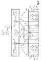
- fig.1 and fig.2 are schematic representations of a fuel supply installation equipping a twin-engine rotorcraft according to a preferred embodiment of the invention.
- a twin-engine rotorcraft comprises a power unit 1 providing the rotorcraft with the mechanical power necessary for its operation.
- the engine group 1 comprises main engines 2,3 combustion and a combustion engine 4 auxiliary fuel supplied by means of a fuel supply unit of the engine group 1.
- twin-engine rotorcraft there are two main engines 2, 3 and are typically each dimensioned to separately provide the mechanical power required for the flight training of at least one rotor 5 of the rotorcraft.
- Said rotor 5 is in particular a rotor commonly designated by main rotor typically providing at least the lift of the rotorcraft, or even its propulsion and / or its flight guidance in the specific case of a helicopter. Said rotor 5 is still potentially, in addition to the main rotor, at least one ancillary rotor providing yaw control of the rotorcraft or even its propulsion in translation in the case of a helicopter at high speeds forward.
- auxiliary motor 4 is dimensioned more weakly than each of the main engines 2,3, with priority being given to the drive of auxiliary members 6 equipping the rotorcraft and mechanical power consumers.
- auxiliary members typically comprise hydraulic power plants, compressors, one or more electric power generating machines and / or a ventilation, heating and / or air conditioning system, or even service equipment, for example.
- the dimensioning of the auxiliary motor 4 confers on it a faculty of producing mechanical power incapable of providing alone a drive of the at least one rotor 5 when the rotorcraft is in flight.
- the auxiliary motor 4 is advantageously used to participate in flight in the drive of the at least one rotor 5 by providing, in certain specific flight phases of the rotorcraft, a supplement of mechanical power in addition to the mechanical power essentially provided by the main engines 2,3.
- the main engines 2,3 and the auxiliary motor 4 are in mechanical connection with a main transmission box 7.
- the various members of the rotorcraft 5,6 consumers of mechanical power are typically driven from the main gearbox 7 of mechanical transmission jointly driven by the main engines 2,3 and by the auxiliary engine 4 in certain phases of flight for which it is required to provide the rotorcraft with optimized mechanical power.
- the fuel supply system of the engine group 1 includes a plurality of fuel supply assemblies 8, 9, 10, including main fuel supply assemblies 8, 9 and an auxiliary fuel supply assembly.
- the main fuel supply units 8, 9 are respectively assigned to the individual fuel supply of the main engines 2,3.
- the auxiliary fuel supply assembly is assigned to the fuel supply of the auxiliary engine 4.
- said transfer circuits typically each comprise at least one transfer pump 17, 18; 19,20 and a transfer line 21,22 provided with at least one ejector 23,24 immersed in the main tanks 11,12.
- Transfer pumps 17,18; 19.20 are preferably two in number and are potentially exploited to form feeding pumps.
- booster pumps are used to supply fuel to the main engines 2,3 to start their startup, until an adequate drive of the main pumps 29,30.
- the main nurseries 13,14 are each provided with a weir 25,26 to evacuate the overflow of fuel out of the main nurseries 13,14 to the main tanks 11,12.
- An intercommunication circuit 31 is preferably arranged between the main nannies 13, 14 of the one and the other of the main fuel supply units 8, 9, for balancing the quantities of fuel respectively contained in the main tanks 11. 12.
- Such an intercommunication circuit 31 is typically implemented selectively by activation of a hydraulic control member 32 of the fuel exchange between the main tanks 11, 12, or even more specifically between the main sinks 13, 14 such that illustrated in the figures.
- a hydraulic regulating device 32 can be controlled according to the needs, for example consisting of an intercommunication valve or an intercommunication pump for example.
- the auxiliary motor 4 being mechanically connected with the at least one rotor 5, the fuel supply of the auxiliary engine 4 must be maintained in the event of failure of any of the main engines 2,3 and / or exhaustion in fuel from any of the main tanks 11,12.
- auxiliary fluid circuit 10 conveying the fuel from each of the main nannies 13,14 to the auxiliary motor 4.
- the auxiliary fluid circuit 10 comprises two auxiliary pumps 33,34 respectively immersed in the main nannies 13,14.
- the auxiliary pumps 33, 34 are jointly placed in fluid communication with an auxiliary duct 35 conveying the fuel from one and the other of the auxiliary pumps 33, 34 to the auxiliary engine 4. In the event of the exhaustion of the fuel at the Inside any one of the main tanks 11, 12, the fuel supply of the auxiliary engine 4 is maintained from the other of the main tanks 11,12.
- the auxiliary duct 35 comprises in particular upstream channels 36, 37 respectively assigned to the removal of fuel from the one and the other of the main tanks 11, 12.
- the upstream channels 36, 37 are each equipped with a 38.39 non-return valve preventing an air passage from any main fuel tank 11, exhausted to the auxiliary engine 4 and / or to the other main tank. 11.12.
- the upstream channels 36, 37 are jointly placed in fluid communication with a downstream channel 40 of the auxiliary duct 35, said downstream channel 40 conveying the fuel from the upstream channels 36, 37 to the auxiliary motor 4.
Landscapes
- Engineering & Computer Science (AREA)
- Aviation & Aerospace Engineering (AREA)
- Chemical & Material Sciences (AREA)
- Combustion & Propulsion (AREA)
- Mechanical Engineering (AREA)
- General Engineering & Computer Science (AREA)
- Cooling, Air Intake And Gas Exhaust, And Fuel Tank Arrangements In Propulsion Units (AREA)
- Automatic Assembly (AREA)
Abstract
Description
- La présente invention est du domaine des giravions et relève plus précisément des modalités d'approvisionnement en carburant d'un groupe de motorisation équipant un giravion.
- La présente invention porte sur une architecture d'alimentation en carburant d'un groupe de motorisation multi-moteur d'un giravion, fournissant une puissance mécanique pour au moins l'entraînement d'au moins un rotor du giravion.
- Les giravions sont des aéronefs à voilure(s) tournante(s) comportant un ou plusieurs rotors procurant au moins la sustentation du giravion, voire aussi sa propulsion et/ou son guidage en vol. Les giravions sont aussi équipés de divers organes auxiliaires consommateurs de puissance mécanique, tels que des compresseurs, des machines productrices d'énergie électrique et/ou une installation de ventilation, de chauffage et/ou de climatisation par exemple.
- Dans ce contexte, les giravions sont équipés d'un groupe de motorisation comprenant un ou plusieurs moteurs à combustion, turbomoteur(s) notamment, dont un ou plusieurs moteurs principaux et un moteur auxiliaire communément désigné par APU (d'après l'acronyme anglais Auxiliary Power Unit). De tels giravions ont notamment été décrits par le Demandeur dans le document
CA 2 831 706 A1 . - Les moteurs principaux sont typiquement dimensionnés pour procurer la puissance mécanique nécessaire à l'entraînement des divers organes consommateurs de puissance mécanique du giravion en vol, dont notamment le ou les rotors et lesdits organes auxiliaires. A cet effet, au moins les moteurs principaux sont en prise sur une chaîne mécanique de transmission de puissance à partir de laquelle sont entraînés les divers organes du giravion consommateurs de puissance mécanique.
- Le moteur auxiliaire est typiquement dimensionné pour procurer la puissance mécanique nécessaire à l'entraînement des organes auxiliaires lorsque le giravion est au sol. A cet effet, le moteur auxiliaire est en prise sur la chaîne mécanique de transmission de puissance en étant habituellement exclu d'une mise en prise mécanique avec le ou les rotors du giravion, compte tenu de son exploitation traditionnellement réservée à l'entraînement des organes auxiliaires hors situation de vol du giravion.
- Selon une catégorie particulière de giravions, communément désignée par catégorie A, le groupe de motorisation comporte plusieurs moteurs principaux procurant simultanément la puissance mécanique nécessaire au giravion en vol. Les giravions de catégorie A peuvent survoler des territoires sensibles sous réserve de la capacité d'au moins un moteur principal à fournir à lui seul la puissance mécanique nécessaire au giravion en vol en cas de panne de l'un des moteurs principaux du groupe de motorisation.
- Dans ce contexte, l'autorisation de survol d'un territoire sensible par un giravion de catégorie A est placée sous condition d'une séparation des moyens procurant aux moteurs principaux leur autonomie individuelle de fonctionnement. En effet, en cas de panne de l'un des moteurs principaux dont le fonctionnement est défectueux, au moins un autre moteur principal doit être apte à entraîner ledit au moins un rotor sans que son fonctionnement ne soit affecté par la panne du moteur principal défectueux.
- Il en est notamment ainsi concernant les modalités d'approvisionnement en carburant des différents moteurs principaux du groupe de motorisation. A cette fin, les giravions de catégorie A sont typiquement équipés d'une installation d'alimentation en carburant du groupe de motorisation regroupant plusieurs ensembles d'alimentation en carburant respectivement affectés à l'alimentation individuelle en carburant des différents moteurs principaux.
- Classiquement, les différents ensembles d'alimentation en carburant sont hydrauliquement isolés les uns des autres. Chaque ensemble d'alimentation en carburant comprend typiquement un réservoir à carburant, potentiellement composé d'une ou de plusieurs réserves de carburant en communication fluidique entre elles, et un circuit fluidique apte à acheminer le carburant depuis le réservoir vers le moteur principal qui lui est affecté.
- L'alimentation individuelle en carburant des moteurs principaux est classiquement réalisée par l'intermédiaire de pompes principales entraînées par les moteurs principaux. Plus particulièrement en considérant un ensemble d'alimentation en carburant donné, le circuit fluidique comprend au moins une ou plusieurs conduites et une dite pompe principale entraînée par le moteur principal. La pompe principale aspire le carburant depuis le réservoir pour l'acheminer vers le moteur principal à travers un conduit d'alimentation du circuit fluidique.
- Subsidiairement, les ensembles d'alimentation en carburant peuvent aussi comprendre chacun au moins une pompe de gavage plongée dans le réservoir pour refouler du carburant vers le moteur principal afin d'amorcer son démarrage.
- Il se pose le problème d'un éventuel épuisement des réservoirs en carburant, pouvant par exemple être provoqué en raison d'une fuite de carburant hors d'un réservoir défectueux ou par suite de la consommation par le moteur principal affecté au réservoir de la totalité du carburant contenu initialement dans ce réservoir.
- C'est pourquoi, il est courant d'équiper chacun des réservoirs d'une nourrice de capacité prédéfinie. Pour un ensemble d'alimentation en carburant donné, la nourrice ménage une réserve de carburant permettant un fonctionnement du moteur principal pendant une durée déterminée en cas d'épuisement du réservoir en carburant.
- La nourrice est classiquement disposée à l'intérieur du réservoir à carburant et est alimentée en carburant par au moins une pompe de transfert. La ou les pompes de transfert acheminent en continu le carburant depuis le réservoir vers la nourrice, la nourrice étant munie d'un déversoir restituant le trop plein de carburant vers le réservoir.
- Ces dispositions sont telles que la nourrice est maintenue pleine en carburant en l'absence d'un défaut de carburant à l'intérieur du réservoir. En cas d'épuisement du réservoir en carburant, le moteur principal dispose d'une autonomie de fonctionnement prédéfinie selon la capacité de la nourrice.
- Le cas échéant et pour réduire le nombre d'organes hydrauliques mis en oeuvre par l'installation d'alimentation en carburant, la ou les pompes de transfert d'un même ensemble d'alimentation en carburant peuvent être en outre exploitées pour former lesdites pompes de gavage.
- Il est aussi courant de ménager un circuit d'intercommunication entre les différents réservoirs de l'installation d'alimentation en carburant, pour permettre un échange de carburant entre les réservoirs en vue notamment d'équilibrer la répartition de la masse de carburant embarqué à bord du giravion. Sous réserve de l'activation d'un organe hydraulique intégré au circuit d'intercommunication, le carburant d'un réservoir peut être exploité pour maintenir une quantité de carburant disponible dans un autre réservoir ou tout au moins dans la nourrice affectée à cet autre réservoir.
- Pour connaître un environnement technologique proche de la présente invention, on pourra par exemple se reporter au document
EP 2 567 896 (EUROCOPTER) qui décrit une telle installation d'alimentation en carburant équipant un giravion bimoteur. Cependant, dans ce document, rien n'indique ni ne suggère d'utiliser un moteur auxiliaire supplémentaire aux deux moteurs principaux destinés à entrainer un rotor principal. Un tel document ne décrit donc pas une alimentation en carburant d'un tel moteur auxiliaire. - D'une manière générale, une recherche constante réside dans une simplification de l'organisation des équipements montés à bord des giravions, pour notamment réduire les coûts de conception, d'installation à bord et de maintenance desdits équipements, ainsi que pour réduire la masse globale des giravions.
- Une telle recherche de simplification concerne entre autre les installations d'alimentation en carburant du groupe de motorisation d'un giravion, comme évoqué dans le document
EP 2 567 896 . - Cependant, une telle recherche de simplification doit s'inscrire dans le champ des contraintes de sécurisation en vol des giravions multi-moteur de catégorie A, notamment en cas d'épuisement en carburant de l'un des réservoirs et/ou en cas de panne de l'un des moteurs principaux.
- Pour ce qui concerne le moteur auxiliaire, celui-ci peut disposer d'un ensemble auxiliaire d'alimentation en carburant dont l'architecture est simplifiée, compte tenu de sa fonction traditionnellement réservée à l'entraînement des organes auxiliaires lorsque le giravion est au sol. Une telle architecture simplifiée de l'ensemble auxiliaire d'alimentation en carburant permet notamment d'exploiter une unique pompe auxiliaire d'alimentation en carburant du moteur auxiliaire pouvant puiser le carburant depuis un réservoir à carburant spécifiquement dédié à l'alimentation en carburant du moteur auxiliaire, voire depuis l'un des réservoirs affecté à l'alimentation en carburant d'un moteur principal.
- Il peut cependant être avantageux d'utiliser en outre le moteur auxiliaire en vol pour participer à l'entraînement du ou des rotors du giravion, en procurant un appoint de puissance mécanique dans des cas de vols particuliers pour lesquels il est requis une puissance mécanique conséquente, tel qu'en vol stationnaire, en phase de décollage ou d'atterrissage, voire encore en cas de panne de l'un des moteurs principaux par exemple.
- Cependant dans ce cas, le moteur auxiliaire est maintenu en prise mécanique sur la chaîne principale de transmission de puissance pour participer, même marginalement, à l'entraînement du ou des rotors du giravion. Dans un tel contexte et dans le cadre des contraintes spécifiques aux giravions de catégorie A, le moteur auxiliaire doit pouvoir fonctionner de manière autonome en cas de panne de l'un des moteurs principaux, notamment en ce qui concerne les modalités d'alimentation en carburant du moteur auxiliaire.
- Par ailleurs il est également connu, tel que décrit dans le document
EP 2 524 871 A1 , d'équiper un aéronef avec deux moteurs principaux et un moteur auxiliaire. Par ailleurs, un tel aéronef comporte deux réservoirs principaux permettant d'alimenter en carburant les deux moteurs principaux. Le moteur auxiliaire est quant à lui alimenté en carburant par un réservoir auxiliaire logé à l'intérieur de l'un des réservoirs principaux. - Cependant dans ce cas, les réservoirs principaux ne comportent pas de nourrice. Au surplus, la ou les pompes auxiliaires permettant d'alimenter en carburant le moteur auxiliaire sont logées dans un seul des réservoirs principaux.
- Dans ce contexte, il est souhaitable de rechercher une solution pour permettre une implantation d'un ensemble d'alimentation en carburant réservé au moteur auxiliaire, s'inscrivant dans la recherche susvisée de simplification de l'architecture d'alimentation en carburant du groupe de motorisation tout en respectant les contraintes liées à l'approvisionnement en carburant des moteurs d'un giravion multi-moteur de catégorie A en prise mécanique avec le ou les rotors du giravion.
- La présente invention s'inscrit dans la recherche d'une telle solution, sur la base du constat qui vient d'être fait et dont relève la démarche de la présente invention.
- En effet dans le cadre d'une éventuelle participation du moteur auxiliaire à l'entraînement marginal du ou des rotors du giravion, les préjugés habituels dans le domaine de l'aéronautique doivent être surmontés pour proposer des modalités viables et sécurisées d'alimentation en carburant du moteur auxiliaire en évitant au mieux de complexifier l'architecture de l'installation d'alimentation en carburant du groupe de motorisation.
- Il en ressort dans la pratique que de tels préjugés font obstacle à une exploitation du moteur auxiliaire pour participer marginalement à l'entraînement du ou des rotors d'un giravion multi-moteur de catégorie A, en raison de la complexification induite de l'architecture d'alimentation en carburant du groupe de motorisation.
- La difficulté d'une telle démarche est notamment constatée dans le cas où ledit giravion multi-moteur est un giravion bimoteur, c'est-à-dire un giravion équipé d'un groupe de motorisation comprenant deux dits moteurs principaux à combustion dimensionnés chacun pour être aptes à entraîner individuellement le ou les rotors du giravion en vol en cas de panne de l'un des moteurs principaux.
- En effet dans un tel contexte en cas de défection de l'un des moteurs principaux, un seul moteur principal est disponible pour procurer la puissance mécanique nécessaire au giravion pour son maintien en vol sous conditions de vol sécurisé, le moteur auxiliaire étant inapte à procurer seul un entraînement du ou des rotors du giravion.
- La présente invention a pour objet un tel giravion bimoteur de catégorie A dont le groupe de motorisation comprend deux dits moteurs principaux à combustion et au moins un dit moteur auxiliaire tels que précédemment définis.
- La présente invention a plus spécifiquement pour objet de proposer un tel giravion bimoteur de catégorie A équipé d'une installation d'alimentation en carburant des moteurs à combustion du groupe de motorisation.
- L'organisation de ladite installation d'alimentation en carburant de la présente invention est recherchée viable sous conditions de vol sécurisé du giravion en cas de défection de l'un des moteurs principaux, dans le cadre d'une simplification des modalités d'alimentation en carburant du moteur auxiliaire. Il doit notamment être pris en compte les contraintes dont relèvent les giravions de catégorie A, compte tenu d'une participation du moteur auxiliaire pour procurer marginalement et/ou temporairement dans des phases de vol spécifiques du giravion un appoint de puissance mécanique participant à l'entraînement du ou des rotors du giravion.
- Le giravion de la présente invention est un giravion bimoteur équipé d'une installation d'alimentation en carburant des moteurs à combustion d'un groupe de motorisation du giravion. Le groupe de motorisation fournit une puissance mécanique exploitée pour l'entraînement d'organes consommateurs de puissance mécanique du giravion par l'intermédiaire d'une chaîne de transmission de puissance mécanique.
- Lesdits organes consommateurs de puissance mécanique comprennent au moins un rotor, dont au moins un rotor principal procurant au moins la sustentation du giravion. Lesdits organes consommateurs de puissance mécanique comprennent encore des organes auxiliaires excluant un quelconque rotor du giravion participant indifféremment isolément ou en combinaison à la sustentation, à la propulsion et/ou au guidage du giravion.
- Par ailleurs le groupe de motorisation comprend deux moteurs principaux à combustion, dont les dimensionnements individuels confèrent aux moteurs principaux une aptitude à entraîner individuellement ledit au moins un rotor pendant une durée prédéfinie en cas de défection de l'un des moteurs principaux.
- Le groupe de motorisation comprend encore au moins un moteur auxiliaire à combustion, dont le dimensionnement confère au moteur auxiliaire une aptitude à entraîner lesdits organes auxiliaires et une inaptitude à entraîner individuellement ledit au moins un rotor en phase de vol du giravion.
- Par ailleurs encore, l'installation d'alimentation en carburant comprend des ensembles principaux d'alimentation en carburant distincts les uns des autres. De tels ensembles principaux d'alimentation en carburant distincts sont respectivement affectés aux moteurs principaux pour leur alimentation individuelle en carburant.
- Chaque ensemble principal d'alimentation en carburant au moins comporte un unique réservoir principal de carburant et un circuit fluidique principal. Le circuit fluidique principal comprend au moins une pompe principale et est un circuit d'acheminement de carburant depuis une nourrice principale équipant le réservoir principal vers le moteur principal auquel est affecté l'ensemble principal d'alimentation en carburant considéré.
- Selon une forme préférée de réalisation, la pompe principale d'un circuit fluidique principal considéré est notamment classiquement entraînée par le moteur principal approvisionné en carburant par ce circuit fluidique principal considéré.
- Chaque ensemble principal d'alimentation en carburant comporte encore un circuit de transfert principal de carburant comprenant notamment au moins une pompe de transfert principale. Le circuit de transfert principal est un circuit d'acheminement de carburant depuis le réservoir principal vers la nourrice principale. Dans ce contexte tel que classiquement, la nourrice principale est munie d'un déversoir restituant un trop plein de carburant vers le réservoir principal.
- Par ailleurs, l'installation d'alimentation en carburant comprend un ensemble auxiliaire d'alimentation en carburant comportant un circuit fluidique auxiliaire. Le circuit fluidique auxiliaire comprend au moins une pompe auxiliaire et est un circuit d'acheminement de carburant depuis les deux réservoirs principaux vers le moteur auxiliaire.
- Dans ce contexte, il est fait le choix conformément à la démarche de la présente invention d'exploiter le moteur auxiliaire pour participer à l'entraînement dudit au moins un rotor, étant compris que le moteur auxiliaire est inapte à procurer seul un entraînement dudit au moins un rotor lorsque le giravion est en vol.
- Dans le cadre de cette démarche, la présente invention propose d'alimenter le moteur auxiliaire en carburant à partir de l'un et l'autre des réservoirs principaux. En cas d'épuisement en carburant de l'un quelconque des réservoirs principaux, le moteur auxiliaire peut être maintenu alimenté en carburant par l'autre des réservoirs principaux.
- Par suite, la mise en prise mécanique du moteur auxiliaire sur la chaîne cinématique d'entraînement du ou des rotors du giravion est viable tout en répondant à des conditions de vol sécurisé en cas d'épuisement en carburant de l'un des réservoirs principaux et cela en évitant une complexification économiquement rédhibitoire de l'installation d'alimentation en carburant du groupe de motorisation du giravion.
- Plus particulièrement selon la présente invention, les réservoirs principaux logent chacun une dite pompe auxiliaire, le circuit fluidique auxiliaire étant un circuit d'acheminement de carburant vers le moteur auxiliaire depuis l'un et l'autre des réservoirs principaux par l'intermédiaire d'un conduit auxiliaire en communication fluidique conjointe avec l'une et l'autre des pompes auxiliaires respectivement logées dans les réservoirs principaux.
- Les réservoirs principaux sont mutualisés pour former conjointement deux réserves de carburant distinctes aptes à permettre individuellement une alimentation du moteur auxiliaire en carburant par l'intermédiaire du circuit fluidique auxiliaire. En cas d'un épuisement en carburant de l'un quelconque des réservoirs principaux provoquant une défection du moteur principal alimenté en carburant à partir du réservoir principal épuisé en carburant, le moteur auxiliaire est maintenu approvisionné en carburant depuis l'autre réservoir principal.
- L'architecture de l'ensemble auxiliaire d'alimentation est simplifiée en l'absence d'un réservoir à carburant spécifique au moteur auxiliaire, tout en étant apte à maintenir un approvisionnement en carburant du moteur auxiliaire en cas d'épuisement en carburant de l'un des réservoirs principaux et tout en répondant à des conditions de vol sécurisé du giravion, voire en optimisant de telles conditions de vol sécurisées en cas de défection de l'un des moteurs principaux par fourniture d'un appoint de puissance mécanique par le moteur auxiliaire pour notamment entraîner le ou les rotors du giravion.
- Selon un agencement préféré du conduit auxiliaire, celui-ci comprend deux canaux auxiliaires amont en communication fluidique respectivement avec l'une et l'autre des pompes auxiliaires. Les canaux auxiliaires amont sont conjointement en communication fluidique avec un canal auxiliaire aval lui-même en communication fluidique avec le moteur auxiliaire.
- Bien entendu selon une telle architecture du conduit auxiliaire, les notions amont et aval sont des notions relatives considérées dans le sens de circulation du carburant à travers le circuit fluidique depuis les pompes auxiliaires vers le moteur auxiliaire.
- Chacun des deux dits canaux auxiliaires amont peut être avantageusement muni d'une valve anti-retour interdisant un passage de fluide de l'un à l'autre des réservoirs principaux. De tels agencements et aménagement du conduit auxiliaire permettent, à partir de modalités de structure simple, d'obtenir une stricte interdiction de passage de fluide de l'un à l'autre des réservoirs principaux par l'intermédiaire du circuit fluidique auxiliaire. De telles dispositions sont notamment utiles en cas d'épuisement en carburant de l'un des réservoirs principaux, pour interdire un passage d'air depuis un réservoir principal épuisé en carburant vers l'autre réservoir principal et/ou vers le moteur auxiliaire.
- Subsidiairement et selon l'organisation propre des ensembles principaux d'alimentation en carburant, les circuits fluidiques principaux sont susceptibles de comporter chacun de telles valves anti-retour interdisant un tel passage d'air depuis les réservoirs principaux vers les moteurs principaux qui leur sont respectivement affectés.
- Selon une forme simple de réalisation, les pompes auxiliaires sont placées en fond des réservoirs principaux qui leur sont respectivement affectés. Un tel placement des pompes auxiliaires en fond des réservoirs principaux exclue, de la composition de l'équipement de l'ensemble auxiliaire d'alimentation en carburant, une nourrice auxiliaire d'approvisionnement en carburant du moteur auxiliaire.
- Cependant, il n'est pas à exclure la possibilité de pourvoir l'ensemble auxiliaire d'alimentation en carburant de nourrices à l'intérieur desquelles sont respectivement plongées les pompes auxiliaires. De telles dispositions procurent un fonctionnement autonome du moteur auxiliaire pendant une durée prédéfinie en cas d'épuisement en carburant de l'un et/ou l'autre des réservoirs principaux. Une telle durée prédéfinie est notamment d'une valeur identique à la durée prédéfinie d'autonomie des moteurs principaux en cas d'épuisement en carburant du réservoir principal qui leur est affecté.
- Plus particulièrement selon une forme de réalisation, les pompes auxiliaires sont respectivement placées en fond des nourrices principales équipant respectivement l'un et l'autre des réservoirs principaux. Les capacités respectives des nourrices principales sont chacune aptes à procurer pendant une durée prédéfinie un approvisionnement en carburant à la fois du moteur auxiliaire et du moteur principal alimenté en carburant depuis la nourrice principale qui lui est affectée.
- Il peut cependant être préféré de limiter la capacité individuelle des nourrices principales. Dans ce cas, il est proposé de pourvoir le circuit fluidique auxiliaire de nourrices auxiliaires respectivement affectées aux pompes auxiliaires.
- Plus particulièrement selon une autre forme de réalisation, les pompes auxiliaires sont respectivement logées en fond de nourrices auxiliaires équipant respectivement l'un et l'autre des réservoirs principaux. Les nourrices auxiliaires sont chacune approvisionnées en carburant depuis le réservoir principal les logeant respectivement.
- Les nourrices auxiliaires sont potentiellement approvisionnées en carburant depuis les réservoirs principaux les logeant respectivement par l'intermédiaire de circuits de transfert auxiliaires respectifs distincts des circuits de transfert principaux.
- De tels circuits de transfert auxiliaires peuvent mettre classiquement en oeuvre chacun au moins une pompe de transfert auxiliaire acheminant le carburant, pour un circuit de transfert auxiliaire considéré, entre le réservoir principal et la nourrice auxiliaire logée dans ce réservoir principal. Subsidiairement, une telle pompe de transfert auxiliaire peut être dans ce cas avantageusement formée par la pompe auxiliaire d'un circuit de transfert auxiliaire considéré.
- Cependant, il est proposé dans le cas où les pompes auxiliaires sont placées en fond de dites nourrices auxiliaires et toujours dans le cadre d'une recherche de simplification de l'architecture de l'installation d'alimentation en carburant du groupe de motorisation, de mutualiser le circuit de transfert principal et le circuit de transfert auxiliaire puisant le carburant dans un même réservoir principal pour alimenter conjointement la nourrice principale et la nourrice auxiliaire logées dans un même réservoir principal.
- Plus particulièrement dans le cas où les pompes auxiliaires sont placées en fond de dites nourrices auxiliaires, il est avantageusement proposé d'approvisionner en carburant les nourrices auxiliaires depuis les réservoirs principaux les logeant respectivement par l'intermédiaire des circuits de transfert principaux avec lesquels les pompes auxiliaires sont en communication fluidique.
- Un exemple de réalisation de la présente invention va être décrit en relation avec les figures des planches annexées, dans lesquelles les
fig.1 etfig.2 sont des représentations schématiques d'une installation d'alimentation en carburant équipant un giravion bimoteur selon une forme préférée de réalisation de l'invention. - Sur la
fig.1 et lafig.2 , un giravion bimoteur comporte un groupe de motorisation 1 fournissant au giravion la puissance mécanique nécessaire à son fonctionnement. Le groupe de motorisation 1 comprend des moteurs principaux 2,3 à combustion et un moteur auxiliaire 4 à combustion alimentés en carburant au moyen d'une installation d'alimentation en carburant du groupe de motorisation 1. - Dans le cadre d'un giravion bimoteur, les moteurs principaux 2,3 sont au nombre de deux et sont typiquement chacun dimensionnés pour fournir isolément la puissance mécanique nécessaire à l'entraînement en vol d'au moins un rotor 5 du giravion.
- Ledit rotor 5 est notamment un rotor communément désigné par rotor principal procurant typiquement au moins la sustentation du giravion, voire aussi sa propulsion et/ou son guidage en vol dans le cas spécifique d'un hélicoptère. Ledit rotor 5 est encore potentiellement, en complément du rotor principal, au moins un rotor annexe procurant le guidage en lacet du giravion voire aussi sa propulsion en translation dans le cas d'un hélicoptère à vitesses élevées d'avancement.
- Le moteur auxiliaire 4 est dimensionné plus faiblement que chacun des moteurs principaux 2,3, en étant prioritairement affecté à l'entraînement d'organes auxiliaires 6 équipant le giravion et consommateurs de puissance mécanique. De tels organes auxiliaires comprennent typiquement des centrales hydrauliques, des compresseurs, une ou plusieurs machines génératrices de courant électrique et/ou une installation de ventilation, de chauffage et/ou de climatisation, voire encore des équipements de servitude par exemple.
- Par distinction vis-à-vis des moteurs principaux 2,3, le dimensionnement du moteur auxiliaire 4 lui confère une faculté de production de puissance mécanique inapte à procurer seule un entraînement dudit au moins un rotor 5 lorsque le giravion est en vol. Cependant, le moteur auxiliaire 4 est avantageusement exploité pour participer en vol à l'entraînement dudit au moins un rotor 5 en fournissant, dans certaines phases de vol spécifiques du giravion, un appoint de puissance mécanique en complément de la puissance mécanique essentiellement fournie par les moteurs principaux 2,3.
- Dans ce contexte, les moteurs principaux 2,3 et le moteur auxiliaire 4 sont en liaison mécanique avec une boîte principale 7 de transmission mécanique. Les différents organes du giravion 5,6 consommateurs de puissance mécanique sont typiquement entraînés à partir de la boîte principale 7 de transmission mécanique entraînée conjointement par les moteurs principaux 2,3 et par le moteur auxiliaire 4 dans certaines phases de vol pour lesquelles il est requis de procurer au giravion une puissance mécanique optimisée.
- L'installation d'alimentation en carburant du groupe de motorisation 1 comprend plusieurs ensembles d'alimentation en carburant 8,9,10, dont des ensembles principaux d'alimentation en carburant 8,9 et un ensemble auxiliaire d'alimentation en carburant.
- Les ensembles principaux d'alimentation en carburant 8,9 sont respectivement affectés à l'alimentation individuelle en carburant des moteurs principaux 2,3. L'ensemble auxiliaire d'alimentation en carburant est affecté à l'alimentation en carburant du moteur auxiliaire 4.
- Chaque ensemble principal d'alimentation en carburant 8,9 comprend classiquement :
- ) un réservoir principal 11,12 à carburant potentiellement composé de plusieurs réserves à carburant placées en communication fluidique entre elles,
- ) une nourrice principale 13,14 logée dans le réservoir principal 11,12 et équipée d'un circuit de transfert 15,16 de carburant depuis le réservoir principal 11,12 vers la nourrice principale 13,14,
- ) un circuit fluidique principal 27,28 comprenant une pompe principale 29,30 puisant le carburant depuis la nourrice principale 13,14 pour alimenter individuellement en carburant un moteur principal 2,3. Sur l'exemple de réalisation illustration illustré, la pompe principale 29,30 est typiquement entraînée par le moteur principal 2,3 alimenté en carburant par la pompe principale 29,30.
- Sur l'exemple de réalisation illustré, lesdits circuits de transfert comprennent typiquement chacun au moins une pompe de transfert 17,18 ; 19,20 ainsi qu'une conduite de transfert 21,22 munie d'au moins un éjecteur 23,24 plongé dans les réservoirs principaux 11,12. Les pompes de transfert 17,18 ; 19,20 sont de préférence au nombre de deux et sont potentiellement exploitées pour former des pompes de gavage. Classiquement, de telles pompes de gavage sont exploitées pour alimenter en carburant les moteurs principaux 2,3 en vue d'amorcer leur démarrage, jusqu'à l'obtention d'un entraînement adéquat des pompes principales 29,30.
- Les nourrices principales 13,14 sont chacune munies d'un déversoir 25,26 permettant d'évacuer le trop plein de carburant hors des nourrices principales 13,14 vers les réservoirs principaux 11,12. Un circuit d'intercommunication 31 est de préférence ménagé entre les nourrices principales 13,14 de l'un et l'autre des ensembles principaux d'alimentation en carburant 8,9, pour équilibrer les quantités de carburant respectivement contenues dans les réservoirs principaux 11,12.
- Une tel circuit d'intercommunication 31 est typiquement mis en oeuvre sélectivement par activation d'un organe hydraulique de régulation 32 de l'échange de carburant entre les réservoirs principaux 11,12, voire plus spécifiquement entre les nourrices principales 13,14 tel qu'illustré sur les figures. Un tel organe hydraulique de régulation 32 est pilotable selon les besoins en étant par exemple constitué d'une vanne d'intercommunication ou d'une pompe d'intercommunication par exemple.
- Dans ce contexte, il se pose le problème d'un éventuel épuisement en carburant de l'un des réservoirs principaux 11,12, voire de l'une des nourrices principales 13,14. Un tel épuisement est potentiellement induit en raison d'une fuite de carburant hors d'un réservoir principal 11,12 devenu défectueux. Classiquement en cas de panne et/ou de perte de l'alimentation en carburant de l'un des moteurs principaux 2,3, l'autre moteur principal 2,3 procure alors seul l'entraînement dudit au moins un rotor 5 pendant une durée prédéfinie déterminant la capacité individuelle des nourrices principales 13,14.
- Cependant, le moteur auxiliaire 4 étant mécaniquement relié avec ledit au moins un rotor 5, l'alimentation en carburant du moteur auxiliaire 4 doit être maintenue en cas de panne de l'un quelconque des moteurs principaux 2,3 et/ou d'épuisement en carburant de l'un quelconque des réservoirs principaux 11,12.
- Dans ce contexte, il est proposé une solution permettant un tel maintien de l'alimentation en carburant du moteur auxiliaire 4, sans pour autant complexifier outre mesure l'architecture de l'installation d'alimentation en carburant du groupe de motorisation 1 ni affecter la sécurisation en vol du giravion en cas de défection de l'un des moteurs principaux 2,3.
- A cet effet sur l'exemple préféré de réalisation illustré sur les figures en raison de l'optimisation de sa simplicité de structure, il est proposé d'alimenter en carburant le moteur auxiliaire 4 au moyen d'un circuit fluidique auxiliaire 10 acheminant le carburant depuis chacune des nourrices principales 13,14 vers le moteur auxiliaire 4. Le circuit fluidique auxiliaire 10 comprend deux pompes auxiliaires 33,34 respectivement plongées dans les nourrices principales 13,14.
- Les pompes auxiliaires 33,34 sont conjointement placées en communication fluidique avec un conduit auxiliaire 35 acheminant le carburant depuis l'une et l'autre des pompes auxiliaires 33,34 vers le moteur auxiliaire 4. En cas d'épuisement du carburant à l'intérieur de l'un quelconque des réservoirs principaux 11,12, l'approvisionnement en carburant du moteur auxiliaire 4 est maintenu à partir de l'autre des réservoirs principaux 11,12.
- Le conduit auxiliaire 35 comprend notamment des canaux amont 36,37 respectivement affectés au prélèvement de carburant depuis l'un et l'autre des réservoirs principaux 11,12. Les canaux amont 36,37 sont chacun équipés d'une valve anti-retour 38,39 interdisant un passage d'air depuis un quelconque réservoir principal 11,12 épuisé en carburant vers le moteur auxiliaire 4 et/ou vers l'autre réservoir principal 11,12. Les canaux amont 36,37 sont placés conjointement en communication fluidique avec un canal aval 40 du conduit auxiliaire 35, ledit canal aval 40 acheminant le carburant depuis les canaux amont 36,37 vers le moteur auxiliaire 4.
Claims (8)
- Giravion bimoteur équipé d'une installation d'alimentation en carburant de moteurs à combustion (2,3,4) d'un groupe de motorisation (1) du giravion, ledit groupe de motorisation (1) fournissant une puissance mécanique exploitée pour l'entraînement d'organes consommateurs de puissance mécanique (5,6) du giravion par l'intermédiaire d'une chaîne de transmission de puissance mécanique,
lesdits organes consommateurs de puissance mécanique (5,6) comprenant :- ) au moins un rotor (5) dont au moins un rotor principal procurant au moins la sustentation du giravion, et- ) des organes auxiliaires (6), lesdits organes auxiliaires (6) excluant un quelconque rotor (5) du giravion participant à la sustentation, à la propulsion et/ou au guidage du giravion,le groupe de motorisation (1) comprenant :- ) deux moteurs principaux (2,3) à combustion dont les dimensionnements individuels leur confèrent une aptitude à entraîner individuellement ledit au moins un rotor (5) pendant une durée prédéfinie en cas de défection de l'un des moteurs principaux (2,3), et- ) au moins un moteur auxiliaire (4) à combustion dont le dimensionnement lui confère une aptitude à entraîner lesdits organes auxiliaires (6) et une inaptitude à entraîner individuellement ledit au moins un rotor (5) en phase de vol du giravion,ledit giravion étant caractérisé en ce que ladite installation d'alimentation en carburant comprend :• des ensembles principaux d'alimentation en carburant (8,9) distincts les uns des autres en étant respectivement affectés aux moteurs principaux (2,3) pour leur alimentation individuelle en carburant, chaque ensemble principal d'alimentation en carburant (8,9) au moins comportant :- un réservoir principal (11,12) de carburant et un circuit fluidique principal (27,28) comprenant au moins une pompe principale (29,30), le circuit fluidique principal (27,28) étant un circuit d'acheminement de carburant depuis une nourrice principale (13,14) équipant le réservoir principal (11,12) vers le moteur principal (2,3) auquel est affecté l'ensemble principal d'alimentation en carburant (8,9) considéré,- un circuit de transfert principal (21,22) de carburant comprenant au moins une pompe de transfert principale (17,18 ;19,20), le circuit de transfert principal (21,22) étant un circuit d'acheminement de carburant depuis le réservoir principal (11,12) vers la nourrice principale (13,14), la nourrice principale étant munie d'un déversoir (25,26) restituant un trop plein de carburant vers le réservoir principal (11,12),• un ensemble auxiliaire d'alimentation en carburant comportant un circuit fluidique auxiliaire (10) comprenant deux pompes auxiliaires (33,34), le circuit fluidique auxiliaire (10) étant un circuit d'acheminement de carburant depuis chaque réservoir principal (11, 12) desdits ensembles d'alimentation principaux en carburant (8,9) vers le moteur auxiliaire (4),et en ce que chaque réservoir principal (11,12) loge une desdites deux pompes auxiliaires (33,34), le circuit fluidique auxiliaire (10) étant un circuit d'acheminement de carburant vers le moteur auxiliaire (4) depuis l'un et l'autre des réservoirs principaux (11,12) par l'intermédiaire d'un conduit auxiliaire (35) en communication fluidique conjointe avec l'une et l'autre des pompes auxiliaires (33,34) respectivement logées dans les réservoirs principaux (11,12). - Giravion bimoteur selon la revendication 1,
caractérisé en ce que le conduit auxiliaire (35) comprend deux canaux auxiliaires amont (36,37) en communication fluidique respectivement avec l'une et l'autre des pompes auxiliaires (33,34), les canaux auxiliaires amont (36,37) étant conjointement en communication fluidique avec un canal auxiliaire aval (40) lui-même en communication fluidique avec le moteur auxiliaire (4). - Giravion bimoteur selon la revendication 2,
caractérisé en ce que chacun des deux dits canaux auxiliaires amont (36,37) est muni d'une valve anti-retour (38,39) interdisant un passage de fluide de l'un à l'autre des réservoirs principaux (11,12). - Giravion bimoteur selon l'une quelconque des revendications 1 à 3,
caractérisé en ce que les pompes auxiliaires (33,34) sont placées en fond des réservoirs principaux (11,12) qui leur sont respectivement affectés en excluant, de la composition de l'équipement de l'ensemble auxiliaire d'alimentation en carburant, une nourrice auxiliaire d'approvisionnement en carburant du moteur auxiliaire (4). - Giravion bimoteur selon l'une quelconque des revendications 1 à 3,
caractérisé en ce que les pompes auxiliaires (33,34) sont respectivement placées en fond des nourrices principales (13,14) équipant respectivement l'un et l'autre des réservoirs principaux (11,12), les capacités respectives des nourrices principales (13,14) étant chacune aptes à procurer pendant une durée prédéfinie un approvisionnement en carburant à la fois du moteur auxiliaire (4) et du moteur principal (2,3) alimenté en carburant depuis la nourrice principale (13,14) qui lui est affectée. - Giravion bimoteur selon l'une quelconque des revendications 1 à 3,
caractérisé en ce que les pompes auxiliaires (33,34) sont respectivement logées en fond de nourrices auxiliaires équipant respectivement l'un et l'autre des réservoirs principaux (11,12), les nourrices auxiliaires étant chacune approvisionnées en carburant depuis le réservoir principal (11,12) les logeant respectivement. - Giravion bimoteur selon la revendication 6,
caractérisé en ce que les nourrices auxiliaires sont approvisionnées en carburant depuis les réservoirs principaux (11,12) les logeant respectivement par l'intermédiaire de circuits de transfert auxiliaires respectifs distincts des circuits de transfert principaux. - Giravion bimoteur selon la revendication 6,
caractérisé en ce que les nourrices auxiliaires sont approvisionnées en carburant depuis les réservoirs principaux (11,12) les logeant respectivement par l'intermédiaire des circuits de transfert principaux (21,22) avec lesquels les pompes auxiliaires (33,34) sont en communication fluidique.
Applications Claiming Priority (1)
| Application Number | Priority Date | Filing Date | Title |
|---|---|---|---|
| FR1401226A FR3021629B1 (fr) | 2014-05-28 | 2014-05-28 | Giravion bimoteur equipe d'une installation d'alimentation en carburant d'un groupe de motorisation comprenant une unite auxiliaire de puissance (apu) |
Publications (2)
| Publication Number | Publication Date |
|---|---|
| EP2949578A1 true EP2949578A1 (fr) | 2015-12-02 |
| EP2949578B1 EP2949578B1 (fr) | 2016-07-27 |
Family
ID=51483472
Family Applications (1)
| Application Number | Title | Priority Date | Filing Date |
|---|---|---|---|
| EP15001347.2A Active EP2949578B1 (fr) | 2014-05-28 | 2015-05-06 | Giravion bimoteur équipé d'une installation d'alimentation en carburant d'un groupe de motorisation comprenant une unité auxiliaire de puissance (apu) |
Country Status (5)
| Country | Link |
|---|---|
| US (1) | US9580184B2 (fr) |
| EP (1) | EP2949578B1 (fr) |
| FR (1) | FR3021629B1 (fr) |
| PL (1) | PL2949578T3 (fr) |
| RU (1) | RU2600180C1 (fr) |
Cited By (1)
| Publication number | Priority date | Publication date | Assignee | Title |
|---|---|---|---|---|
| US9580184B2 (en) * | 2014-05-28 | 2017-02-28 | Airbus Helicopters | Twin-engined rotorcraft having a fuel supply installation for a power plant auxiliary power unit (APU) |
Families Citing this family (8)
| Publication number | Priority date | Publication date | Assignee | Title |
|---|---|---|---|---|
| US11174013B2 (en) | 2019-02-05 | 2021-11-16 | Textron Innovations Inc. | Failsafe multimode clutch assemblies for rotorcraft |
| US12049304B2 (en) | 2019-02-05 | 2024-07-30 | Textron Innovations Inc. | Tail rotor isolation systems for rotorcraft |
| US10793284B2 (en) | 2019-02-05 | 2020-10-06 | Bell Textron Inc. | Multimode clutch assemblies for rotorcraft |
| US11174014B2 (en) | 2019-02-05 | 2021-11-16 | Textron Innovations Inc. | Failsafe multimode clutch assemblies for rotorcraft |
| US10788088B2 (en) | 2019-02-05 | 2020-09-29 | Bell Textron Inc. | Multimode powertrains for rotorcraft |
| US11174015B2 (en) | 2019-02-05 | 2021-11-16 | Textron Innovations Inc. | Multimode clutch assemblies having engagement status sensors |
| US11708868B2 (en) | 2019-02-13 | 2023-07-25 | Textron Innovations Inc. | Failsafe multimode clutch assemblies for rotorcraft |
| US11104430B2 (en) | 2019-09-27 | 2021-08-31 | Textron Innovations Inc. | Multimode powertrains for multi engine rotorcraft |
Citations (3)
| Publication number | Priority date | Publication date | Assignee | Title |
|---|---|---|---|---|
| EP2524871A1 (fr) | 2011-05-18 | 2012-11-21 | Dassault Aviation | Dispositif de stockage de combustible dans un aéronef, système et méthode de gestion associés. |
| EP2567896A1 (fr) | 2011-09-09 | 2013-03-13 | Eurocopter | Architecture d'alimentation en carburant d'un groupe de motorisation d'une voilure tournante équipant un giravion |
| CA2831706A1 (fr) | 2012-11-26 | 2014-05-26 | Eurocopter | Procede et aeronef a voilure tournante muni de trois moteurs |
Family Cites Families (6)
| Publication number | Priority date | Publication date | Assignee | Title |
|---|---|---|---|---|
| SU1108693A1 (ru) * | 1983-03-31 | 1996-04-27 | А.П. Белов | Топливная система летательного аппарата |
| US5321945A (en) * | 1990-04-02 | 1994-06-21 | Honeywell Inc. | Apparatus for controlling fuel transfers in a distributed fuel tank system |
| EP0670264A1 (fr) * | 1994-03-02 | 1995-09-06 | Daimler-Benz Aerospace Aktiengesellschaft | Système d'alimentation en combustible |
| RU4733U1 (ru) * | 1996-03-29 | 1997-08-16 | Акционерное общество открытого типа "Московский вертолетный завод им.М.Л.Миля" | Топливная система вертолета |
| EP2285681B1 (fr) * | 2008-05-13 | 2018-09-12 | Sikorsky Aircraft Corporation | Système d'alimentation en carburant |
| FR3021629B1 (fr) * | 2014-05-28 | 2016-06-10 | Airbus Helicopters | Giravion bimoteur equipe d'une installation d'alimentation en carburant d'un groupe de motorisation comprenant une unite auxiliaire de puissance (apu) |
-
2014
- 2014-05-28 FR FR1401226A patent/FR3021629B1/fr active Active
-
2015
- 2015-05-06 PL PL15001347T patent/PL2949578T3/pl unknown
- 2015-05-06 EP EP15001347.2A patent/EP2949578B1/fr active Active
- 2015-05-25 RU RU2015119679/11A patent/RU2600180C1/ru active
- 2015-05-27 US US14/722,365 patent/US9580184B2/en not_active Expired - Fee Related
Patent Citations (3)
| Publication number | Priority date | Publication date | Assignee | Title |
|---|---|---|---|---|
| EP2524871A1 (fr) | 2011-05-18 | 2012-11-21 | Dassault Aviation | Dispositif de stockage de combustible dans un aéronef, système et méthode de gestion associés. |
| EP2567896A1 (fr) | 2011-09-09 | 2013-03-13 | Eurocopter | Architecture d'alimentation en carburant d'un groupe de motorisation d'une voilure tournante équipant un giravion |
| CA2831706A1 (fr) | 2012-11-26 | 2014-05-26 | Eurocopter | Procede et aeronef a voilure tournante muni de trois moteurs |
Cited By (1)
| Publication number | Priority date | Publication date | Assignee | Title |
|---|---|---|---|---|
| US9580184B2 (en) * | 2014-05-28 | 2017-02-28 | Airbus Helicopters | Twin-engined rotorcraft having a fuel supply installation for a power plant auxiliary power unit (APU) |
Also Published As
| Publication number | Publication date |
|---|---|
| US9580184B2 (en) | 2017-02-28 |
| EP2949578B1 (fr) | 2016-07-27 |
| FR3021629B1 (fr) | 2016-06-10 |
| FR3021629A1 (fr) | 2015-12-04 |
| PL2949578T3 (pl) | 2017-01-31 |
| US20160272338A1 (en) | 2016-09-22 |
| RU2600180C1 (ru) | 2016-10-20 |
Similar Documents
| Publication | Publication Date | Title |
|---|---|---|
| EP2949578B1 (fr) | Giravion bimoteur équipé d'une installation d'alimentation en carburant d'un groupe de motorisation comprenant une unité auxiliaire de puissance (apu) | |
| EP3224462B1 (fr) | Dispositif de refroidissement pour une turbomachine alimente par un circuit de decharge | |
| EP2524869B1 (fr) | Système autonome de génération de puissance électrique et de conditionnement pour un aéronef, aéronef et procédé associés. | |
| US8870699B2 (en) | Lubrication oil system for a reduction gearbox | |
| EP2750969B1 (fr) | Aéronef équipé d'un groupe électromoteur distribué à roues libres | |
| FR2491141A1 (fr) | Dispositif d'alimentation en huile pour moteur d'avion a turbine a gaz | |
| FR2979614A1 (fr) | Transmission electromagnetique de puissance pour aeronef a voilure tournante ou fixe. | |
| EP2801707A1 (fr) | Circuit de lubrification de turbomachine avec vanne anti-siphon pour windmilling | |
| EP2181036A2 (fr) | Dispositif aerien | |
| FR2957207A1 (fr) | Groupe electromoteur distribue. | |
| EP2657134B1 (fr) | Réseau d'alimentation en carburant d'un moteur de giravion, comprenant des moyens d'amorçage d'une pompe d'aspiration du carburant depuis une nourrice | |
| EP2567896B1 (fr) | Architecture d'alimentation en carburant d'un groupe de motorisation d'une voilure tournante équipant un giravion | |
| RU2468227C1 (ru) | Масляная система авиационного газотурбинного двигателя | |
| FR3075875A1 (fr) | Circuit d'huile pour turbomachine a boucle d'huile auxiliaire | |
| EP4445464A1 (fr) | Procédé de protection en tension d'un système électrique multi sources | |
| EP3087264B1 (fr) | Démarreur à air de turbomachine comportant des premier et deuxième compartiments de lubrification | |
| EP2524871B1 (fr) | Système autonome de génération de puissance électrique pour aéronef et méthode de gestion associé | |
| FR3066754A1 (fr) | Systeme de conditionnement d'air d'une cabine d'aeronef et procede de fonctionnement associe | |
| FR3005486A1 (fr) | Lubrification dans une turbomachine | |
| FR3024498A1 (fr) | Ensemble de turbomachine comportant deux corps et des moyens de guidage internes d'un fluide d'ecoulement vers un element a alimenter |
Legal Events
| Date | Code | Title | Description |
|---|---|---|---|
| AK | Designated contracting states |
Kind code of ref document: A1 Designated state(s): AL AT BE BG CH CY CZ DE DK EE ES FI FR GB GR HR HU IE IS IT LI LT LU LV MC MK MT NL NO PL PT RO RS SE SI SK SM TR |
|
| AX | Request for extension of the european patent |
Extension state: BA ME |
|
| PUAI | Public reference made under article 153(3) epc to a published international application that has entered the european phase |
Free format text: ORIGINAL CODE: 0009012 |
|
| GRAP | Despatch of communication of intention to grant a patent |
Free format text: ORIGINAL CODE: EPIDOSNIGR1 |
|
| 17P | Request for examination filed |
Effective date: 20160201 |
|
| RBV | Designated contracting states (corrected) |
Designated state(s): AL AT BE BG CH CY CZ DE DK EE ES FI FR GB GR HR HU IE IS IT LI LT LU LV MC MK MT NL NO PL PT RO RS SE SI SK SM TR |
|
| RIC1 | Information provided on ipc code assigned before grant |
Ipc: B64D 37/20 20060101ALI20160224BHEP Ipc: B64C 27/12 20060101AFI20160224BHEP Ipc: B64D 37/08 20060101ALI20160224BHEP Ipc: B64D 41/00 20060101ALI20160224BHEP |
|
| INTG | Intention to grant announced |
Effective date: 20160315 |
|
| GRAS | Grant fee paid |
Free format text: ORIGINAL CODE: EPIDOSNIGR3 |
|
| GRAA | (expected) grant |
Free format text: ORIGINAL CODE: 0009210 |
|
| AK | Designated contracting states |
Kind code of ref document: B1 Designated state(s): AL AT BE BG CH CY CZ DE DK EE ES FI FR GB GR HR HU IE IS IT LI LT LU LV MC MK MT NL NO PL PT RO RS SE SI SK SM TR |
|
| REG | Reference to a national code |
Ref country code: GB Ref legal event code: FG4D Free format text: NOT ENGLISH |
|
| REG | Reference to a national code |
Ref country code: CH Ref legal event code: EP |
|
| REG | Reference to a national code |
Ref country code: AT Ref legal event code: REF Ref document number: 815566 Country of ref document: AT Kind code of ref document: T Effective date: 20160815 |
|
| REG | Reference to a national code |
Ref country code: IE Ref legal event code: FG4D Free format text: LANGUAGE OF EP DOCUMENT: FRENCH |
|
| REG | Reference to a national code |
Ref country code: DE Ref legal event code: R096 Ref document number: 602015000143 Country of ref document: DE |
|
| REG | Reference to a national code |
Ref country code: LT Ref legal event code: MG4D |
|
| REG | Reference to a national code |
Ref country code: NL Ref legal event code: MP Effective date: 20160727 |
|
| REG | Reference to a national code |
Ref country code: AT Ref legal event code: MK05 Ref document number: 815566 Country of ref document: AT Kind code of ref document: T Effective date: 20160727 |
|
| PG25 | Lapsed in a contracting state [announced via postgrant information from national office to epo] |
Ref country code: RS Free format text: LAPSE BECAUSE OF FAILURE TO SUBMIT A TRANSLATION OF THE DESCRIPTION OR TO PAY THE FEE WITHIN THE PRESCRIBED TIME-LIMIT Effective date: 20160727 Ref country code: IS Free format text: LAPSE BECAUSE OF FAILURE TO SUBMIT A TRANSLATION OF THE DESCRIPTION OR TO PAY THE FEE WITHIN THE PRESCRIBED TIME-LIMIT Effective date: 20161127 Ref country code: LT Free format text: LAPSE BECAUSE OF FAILURE TO SUBMIT A TRANSLATION OF THE DESCRIPTION OR TO PAY THE FEE WITHIN THE PRESCRIBED TIME-LIMIT Effective date: 20160727 Ref country code: NL Free format text: LAPSE BECAUSE OF FAILURE TO SUBMIT A TRANSLATION OF THE DESCRIPTION OR TO PAY THE FEE WITHIN THE PRESCRIBED TIME-LIMIT Effective date: 20160727 Ref country code: FI Free format text: LAPSE BECAUSE OF FAILURE TO SUBMIT A TRANSLATION OF THE DESCRIPTION OR TO PAY THE FEE WITHIN THE PRESCRIBED TIME-LIMIT Effective date: 20160727 Ref country code: HR Free format text: LAPSE BECAUSE OF FAILURE TO SUBMIT A TRANSLATION OF THE DESCRIPTION OR TO PAY THE FEE WITHIN THE PRESCRIBED TIME-LIMIT Effective date: 20160727 Ref country code: NO Free format text: LAPSE BECAUSE OF FAILURE TO SUBMIT A TRANSLATION OF THE DESCRIPTION OR TO PAY THE FEE WITHIN THE PRESCRIBED TIME-LIMIT Effective date: 20161027 |
|
| PG25 | Lapsed in a contracting state [announced via postgrant information from national office to epo] |
Ref country code: PT Free format text: LAPSE BECAUSE OF FAILURE TO SUBMIT A TRANSLATION OF THE DESCRIPTION OR TO PAY THE FEE WITHIN THE PRESCRIBED TIME-LIMIT Effective date: 20161128 Ref country code: ES Free format text: LAPSE BECAUSE OF FAILURE TO SUBMIT A TRANSLATION OF THE DESCRIPTION OR TO PAY THE FEE WITHIN THE PRESCRIBED TIME-LIMIT Effective date: 20160727 Ref country code: GR Free format text: LAPSE BECAUSE OF FAILURE TO SUBMIT A TRANSLATION OF THE DESCRIPTION OR TO PAY THE FEE WITHIN THE PRESCRIBED TIME-LIMIT Effective date: 20161028 Ref country code: AT Free format text: LAPSE BECAUSE OF FAILURE TO SUBMIT A TRANSLATION OF THE DESCRIPTION OR TO PAY THE FEE WITHIN THE PRESCRIBED TIME-LIMIT Effective date: 20160727 Ref country code: SE Free format text: LAPSE BECAUSE OF FAILURE TO SUBMIT A TRANSLATION OF THE DESCRIPTION OR TO PAY THE FEE WITHIN THE PRESCRIBED TIME-LIMIT Effective date: 20160727 Ref country code: LV Free format text: LAPSE BECAUSE OF FAILURE TO SUBMIT A TRANSLATION OF THE DESCRIPTION OR TO PAY THE FEE WITHIN THE PRESCRIBED TIME-LIMIT Effective date: 20160727 |
|
| PG25 | Lapsed in a contracting state [announced via postgrant information from national office to epo] |
Ref country code: EE Free format text: LAPSE BECAUSE OF FAILURE TO SUBMIT A TRANSLATION OF THE DESCRIPTION OR TO PAY THE FEE WITHIN THE PRESCRIBED TIME-LIMIT Effective date: 20160727 Ref country code: RO Free format text: LAPSE BECAUSE OF FAILURE TO SUBMIT A TRANSLATION OF THE DESCRIPTION OR TO PAY THE FEE WITHIN THE PRESCRIBED TIME-LIMIT Effective date: 20160727 |
|
| REG | Reference to a national code |
Ref country code: DE Ref legal event code: R097 Ref document number: 602015000143 Country of ref document: DE |
|
| REG | Reference to a national code |
Ref country code: FR Ref legal event code: PLFP Year of fee payment: 3 |
|
| PG25 | Lapsed in a contracting state [announced via postgrant information from national office to epo] |
Ref country code: CZ Free format text: LAPSE BECAUSE OF FAILURE TO SUBMIT A TRANSLATION OF THE DESCRIPTION OR TO PAY THE FEE WITHIN THE PRESCRIBED TIME-LIMIT Effective date: 20160727 Ref country code: SM Free format text: LAPSE BECAUSE OF FAILURE TO SUBMIT A TRANSLATION OF THE DESCRIPTION OR TO PAY THE FEE WITHIN THE PRESCRIBED TIME-LIMIT Effective date: 20160727 Ref country code: BG Free format text: LAPSE BECAUSE OF FAILURE TO SUBMIT A TRANSLATION OF THE DESCRIPTION OR TO PAY THE FEE WITHIN THE PRESCRIBED TIME-LIMIT Effective date: 20161027 Ref country code: DK Free format text: LAPSE BECAUSE OF FAILURE TO SUBMIT A TRANSLATION OF THE DESCRIPTION OR TO PAY THE FEE WITHIN THE PRESCRIBED TIME-LIMIT Effective date: 20160727 Ref country code: SK Free format text: LAPSE BECAUSE OF FAILURE TO SUBMIT A TRANSLATION OF THE DESCRIPTION OR TO PAY THE FEE WITHIN THE PRESCRIBED TIME-LIMIT Effective date: 20160727 |
|
| PLBE | No opposition filed within time limit |
Free format text: ORIGINAL CODE: 0009261 |
|
| STAA | Information on the status of an ep patent application or granted ep patent |
Free format text: STATUS: NO OPPOSITION FILED WITHIN TIME LIMIT |
|
| 26N | No opposition filed |
Effective date: 20170502 |
|
| PG25 | Lapsed in a contracting state [announced via postgrant information from national office to epo] |
Ref country code: SI Free format text: LAPSE BECAUSE OF FAILURE TO SUBMIT A TRANSLATION OF THE DESCRIPTION OR TO PAY THE FEE WITHIN THE PRESCRIBED TIME-LIMIT Effective date: 20160727 Ref country code: LU Free format text: LAPSE BECAUSE OF NON-PAYMENT OF DUE FEES Effective date: 20170531 |
|
| REG | Reference to a national code |
Ref country code: DE Ref legal event code: R119 Ref document number: 602015000143 Country of ref document: DE |
|
| PG25 | Lapsed in a contracting state [announced via postgrant information from national office to epo] |
Ref country code: MC Free format text: LAPSE BECAUSE OF FAILURE TO SUBMIT A TRANSLATION OF THE DESCRIPTION OR TO PAY THE FEE WITHIN THE PRESCRIBED TIME-LIMIT Effective date: 20160727 |
|
| REG | Reference to a national code |
Ref country code: IE Ref legal event code: MM4A |
|
| PG25 | Lapsed in a contracting state [announced via postgrant information from national office to epo] |
Ref country code: LU Free format text: LAPSE BECAUSE OF NON-PAYMENT OF DUE FEES Effective date: 20170506 |
|
| REG | Reference to a national code |
Ref country code: BE Ref legal event code: MM Effective date: 20170531 |
|
| PG25 | Lapsed in a contracting state [announced via postgrant information from national office to epo] |
Ref country code: DE Free format text: LAPSE BECAUSE OF NON-PAYMENT OF DUE FEES Effective date: 20171201 Ref country code: IE Free format text: LAPSE BECAUSE OF NON-PAYMENT OF DUE FEES Effective date: 20170506 |
|
| REG | Reference to a national code |
Ref country code: FR Ref legal event code: PLFP Year of fee payment: 4 |
|
| PG25 | Lapsed in a contracting state [announced via postgrant information from national office to epo] |
Ref country code: BE Free format text: LAPSE BECAUSE OF NON-PAYMENT OF DUE FEES Effective date: 20170531 |
|
| PG25 | Lapsed in a contracting state [announced via postgrant information from national office to epo] |
Ref country code: MT Free format text: LAPSE BECAUSE OF FAILURE TO SUBMIT A TRANSLATION OF THE DESCRIPTION OR TO PAY THE FEE WITHIN THE PRESCRIBED TIME-LIMIT Effective date: 20160727 |
|
| PG25 | Lapsed in a contracting state [announced via postgrant information from national office to epo] |
Ref country code: AL Free format text: LAPSE BECAUSE OF FAILURE TO SUBMIT A TRANSLATION OF THE DESCRIPTION OR TO PAY THE FEE WITHIN THE PRESCRIBED TIME-LIMIT Effective date: 20160727 |
|
| REG | Reference to a national code |
Ref country code: CH Ref legal event code: PL |
|
| PG25 | Lapsed in a contracting state [announced via postgrant information from national office to epo] |
Ref country code: CH Free format text: LAPSE BECAUSE OF NON-PAYMENT OF DUE FEES Effective date: 20180531 Ref country code: LI Free format text: LAPSE BECAUSE OF NON-PAYMENT OF DUE FEES Effective date: 20180531 |
|
| PG25 | Lapsed in a contracting state [announced via postgrant information from national office to epo] |
Ref country code: HU Free format text: LAPSE BECAUSE OF FAILURE TO SUBMIT A TRANSLATION OF THE DESCRIPTION OR TO PAY THE FEE WITHIN THE PRESCRIBED TIME-LIMIT; INVALID AB INITIO Effective date: 20150506 |
|
| PG25 | Lapsed in a contracting state [announced via postgrant information from national office to epo] |
Ref country code: CY Free format text: LAPSE BECAUSE OF FAILURE TO SUBMIT A TRANSLATION OF THE DESCRIPTION OR TO PAY THE FEE WITHIN THE PRESCRIBED TIME-LIMIT Effective date: 20160727 |
|
| PG25 | Lapsed in a contracting state [announced via postgrant information from national office to epo] |
Ref country code: MK Free format text: LAPSE BECAUSE OF FAILURE TO SUBMIT A TRANSLATION OF THE DESCRIPTION OR TO PAY THE FEE WITHIN THE PRESCRIBED TIME-LIMIT Effective date: 20160727 |
|
| GBPC | Gb: european patent ceased through non-payment of renewal fee |
Effective date: 20190506 |
|
| PG25 | Lapsed in a contracting state [announced via postgrant information from national office to epo] |
Ref country code: TR Free format text: LAPSE BECAUSE OF FAILURE TO SUBMIT A TRANSLATION OF THE DESCRIPTION OR TO PAY THE FEE WITHIN THE PRESCRIBED TIME-LIMIT Effective date: 20160727 |
|
| PG25 | Lapsed in a contracting state [announced via postgrant information from national office to epo] |
Ref country code: GB Free format text: LAPSE BECAUSE OF NON-PAYMENT OF DUE FEES Effective date: 20190506 |
|
| P01 | Opt-out of the competence of the unified patent court (upc) registered |
Effective date: 20230530 |
|
| PGFP | Annual fee paid to national office [announced via postgrant information from national office to epo] |
Ref country code: PL Payment date: 20230428 Year of fee payment: 9 |
|
| PGFP | Annual fee paid to national office [announced via postgrant information from national office to epo] |
Ref country code: IT Payment date: 20250527 Year of fee payment: 11 |
|
| PGFP | Annual fee paid to national office [announced via postgrant information from national office to epo] |
Ref country code: FR Payment date: 20250528 Year of fee payment: 11 |