EP2949576A1 - Bassinet with illumination system - Google Patents
Bassinet with illumination system Download PDFInfo
- Publication number
- EP2949576A1 EP2949576A1 EP15001431.4A EP15001431A EP2949576A1 EP 2949576 A1 EP2949576 A1 EP 2949576A1 EP 15001431 A EP15001431 A EP 15001431A EP 2949576 A1 EP2949576 A1 EP 2949576A1
- Authority
- EP
- European Patent Office
- Prior art keywords
- housing
- light source
- aperture
- user input
- bassinet
- Prior art date
- Legal status (The legal status is an assumption and is not a legal conclusion. Google has not performed a legal analysis and makes no representation as to the accuracy of the status listed.)
- Withdrawn
Links
- 238000005286 illumination Methods 0.000 title claims abstract description 42
- 230000007423 decrease Effects 0.000 claims description 2
- 238000000034 method Methods 0.000 description 14
- 230000008878 coupling Effects 0.000 description 13
- 238000010168 coupling process Methods 0.000 description 13
- 238000005859 coupling reaction Methods 0.000 description 13
- 238000004891 communication Methods 0.000 description 7
- 238000002620 method output Methods 0.000 description 4
- 230000003993 interaction Effects 0.000 description 3
- 230000007246 mechanism Effects 0.000 description 3
- 238000012546 transfer Methods 0.000 description 3
- 238000010586 diagram Methods 0.000 description 2
- 239000004744 fabric Substances 0.000 description 2
- 239000000463 material Substances 0.000 description 2
- 238000005424 photoluminescence Methods 0.000 description 2
- 229920000642 polymer Polymers 0.000 description 2
- 238000013461 design Methods 0.000 description 1
- 230000006870 function Effects 0.000 description 1
- 239000002184 metal Substances 0.000 description 1
- 229910001092 metal group alloy Inorganic materials 0.000 description 1
- 238000005192 partition Methods 0.000 description 1
- 238000012545 processing Methods 0.000 description 1
- 230000000452 restraining effect Effects 0.000 description 1
- 239000000758 substrate Substances 0.000 description 1
Images



Classifications
-
- F—MECHANICAL ENGINEERING; LIGHTING; HEATING; WEAPONS; BLASTING
- F21—LIGHTING
- F21V—FUNCTIONAL FEATURES OR DETAILS OF LIGHTING DEVICES OR SYSTEMS THEREOF; STRUCTURAL COMBINATIONS OF LIGHTING DEVICES WITH OTHER ARTICLES, NOT OTHERWISE PROVIDED FOR
- F21V33/00—Structural combinations of lighting devices with other articles, not otherwise provided for
- F21V33/0004—Personal or domestic articles
- F21V33/0012—Furniture
-
- B—PERFORMING OPERATIONS; TRANSPORTING
- B64—AIRCRAFT; AVIATION; COSMONAUTICS
- B64D—EQUIPMENT FOR FITTING IN OR TO AIRCRAFT; FLIGHT SUITS; PARACHUTES; ARRANGEMENT OR MOUNTING OF POWER PLANTS OR PROPULSION TRANSMISSIONS IN AIRCRAFT
- B64D11/00—Passenger or crew accommodation; Flight-deck installations not otherwise provided for
-
- B—PERFORMING OPERATIONS; TRANSPORTING
- B64—AIRCRAFT; AVIATION; COSMONAUTICS
- B64D—EQUIPMENT FOR FITTING IN OR TO AIRCRAFT; FLIGHT SUITS; PARACHUTES; ARRANGEMENT OR MOUNTING OF POWER PLANTS OR PROPULSION TRANSMISSIONS IN AIRCRAFT
- B64D11/00—Passenger or crew accommodation; Flight-deck installations not otherwise provided for
- B64D11/06—Arrangements of seats, or adaptations or details specially adapted for aircraft seats
- B64D11/0612—Arrangements of seats, or adaptations or details specially adapted for aircraft seats specially adapted for children
-
- B—PERFORMING OPERATIONS; TRANSPORTING
- B64—AIRCRAFT; AVIATION; COSMONAUTICS
- B64D—EQUIPMENT FOR FITTING IN OR TO AIRCRAFT; FLIGHT SUITS; PARACHUTES; ARRANGEMENT OR MOUNTING OF POWER PLANTS OR PROPULSION TRANSMISSIONS IN AIRCRAFT
- B64D47/00—Equipment not otherwise provided for
- B64D47/02—Arrangements or adaptations of signal or lighting devices
-
- F—MECHANICAL ENGINEERING; LIGHTING; HEATING; WEAPONS; BLASTING
- F21—LIGHTING
- F21V—FUNCTIONAL FEATURES OR DETAILS OF LIGHTING DEVICES OR SYSTEMS THEREOF; STRUCTURAL COMBINATIONS OF LIGHTING DEVICES WITH OTHER ARTICLES, NOT OTHERWISE PROVIDED FOR
- F21V23/00—Arrangement of electric circuit elements in or on lighting devices
- F21V23/02—Arrangement of electric circuit elements in or on lighting devices the elements being transformers, impedances or power supply units, e.g. a transformer with a rectifier
- F21V23/023—Power supplies in a casing
-
- F—MECHANICAL ENGINEERING; LIGHTING; HEATING; WEAPONS; BLASTING
- F21—LIGHTING
- F21V—FUNCTIONAL FEATURES OR DETAILS OF LIGHTING DEVICES OR SYSTEMS THEREOF; STRUCTURAL COMBINATIONS OF LIGHTING DEVICES WITH OTHER ARTICLES, NOT OTHERWISE PROVIDED FOR
- F21V23/00—Arrangement of electric circuit elements in or on lighting devices
- F21V23/04—Arrangement of electric circuit elements in or on lighting devices the elements being switches
-
- F—MECHANICAL ENGINEERING; LIGHTING; HEATING; WEAPONS; BLASTING
- F21—LIGHTING
- F21W—INDEXING SCHEME ASSOCIATED WITH SUBCLASSES F21K, F21L, F21S and F21V, RELATING TO USES OR APPLICATIONS OF LIGHTING DEVICES OR SYSTEMS
- F21W2131/00—Use or application of lighting devices or systems not provided for in codes F21W2102/00-F21W2121/00
- F21W2131/30—Lighting for domestic or personal use
- F21W2131/301—Lighting for domestic or personal use for furniture
-
- F—MECHANICAL ENGINEERING; LIGHTING; HEATING; WEAPONS; BLASTING
- F21—LIGHTING
- F21Y—INDEXING SCHEME ASSOCIATED WITH SUBCLASSES F21K, F21L, F21S and F21V, RELATING TO THE FORM OR THE KIND OF THE LIGHT SOURCES OR OF THE COLOUR OF THE LIGHT EMITTED
- F21Y2115/00—Light-generating elements of semiconductor light sources
- F21Y2115/10—Light-emitting diodes [LED]
Definitions
- the present disclosure generally relates to mobile platforms, such as aircraft, and more particularly relates to a system for illumination of a baby bassinet onboard an aircraft.
- a bassinet may be provided in a passenger cabin of the aircraft to accommodate infant passengers onboard the aircraft.
- one or more of the lights in the passenger cabin may be dimmed or turned off to allow the passengers onboard the aircraft to rest. In situations in which the lights in the passenger cabin are dimmed or turned off, it may be difficult to attend to the infant passenger in the bassinet.
- an illumination system for a bassinet of a mobile platform includes a housing including a first housing part defining at least one aperture and a second housing part coupled to the first housing part so as to define a housing cavity.
- the system also includes at least one light source disposed within the housing cavity and adjacent to the at least one aperture such that light output by the at least one light source is directed out of the first housing part.
- the system includes a user input device coupled to the housing that receives user input and a power source.
- the system also includes a control module that supplies power from the power source to the at least one light source to illuminate the bassinet based on the user input.
- a bassinet for a mobile platform includes a first rail that defines a perimeter of a cavity.
- the first rail is adapted to be coupled to the mobile platform.
- the bassinet includes a support structure coupled to the first rail that defines a plurality of sides and the cavity.
- the bassinet also includes a housing that defines a housing cavity and includes a first aperture spaced apart from a second aperture along a longitudinal axis of the housing. The housing is directly coupled to the first rail.
- the bassinet includes a first light source disposed within the housing cavity adjacent to the first aperture such that light output by the first light source is directed out of the housing and a second light source disposed within the housing cavity adjacent to the second aperture such that light output by the second light source is directed out of the housing.
- the bassinet also includes a power source and a control module that supplies power from the power source to the first light source and second light source to illuminate the cavity.
- an aircraft in one embodiment, includes a bassinet having a plurality of sides and a surface that cooperate to define a cavity. The plurality of sides form a perimeter of the cavity.
- the aircraft further includes an illumination system coupled to the perimeter of the bassinet.
- the illumination system includes a housing including a first housing part defining at least one aperture and a second housing part coupled to the first housing part so as to define a housing cavity.
- the second housing part is coupled to the perimeter of the bassinet.
- the illumination system includes at least one light source disposed within the housing cavity and adjacent to the at least one aperture such that light output by the at least one light source is directed out of the first housing part.
- the illumination system also includes a user input device coupled to the housing that receives user input and a power source disposed within the housing cavity.
- the illumination system includes a control module that supplies power from the power source to the at least one light source to illuminate the cavity of the bassinet based on the user input.
- module refers to any hardware, software, firmware, electronic control component, processing logic, and/or processor device, individually or in any combination, including without limitation: application specific integrated circuit (ASIC), an electronic circuit, a processor (shared, dedicated, or group) and memory that executes one or more software or firmware programs, a combinational logic circuit, and/or other suitable components that provide the described functionality.
- ASIC application specific integrated circuit
- the aircraft 10 includes a passenger cabin 12.
- the passenger cabin 12 generally includes one or more seats 14, and may include one or more monuments 16.
- the monuments 16 include, but are not limited to, toilet monuments, kitchen or galley monuments, partitions, class dividers, etc., as known to one skilled in the art.
- the passenger cabin 12 includes a bassinet system 18. While the bassinet system 18 is illustrated herein as being coupled to the monument 16, the bassinet system 18 may be coupled to any suitable portion of the passenger cabin 12, such as one of the seats 14, for example.
- the illustration herein is merely exemplary.
- the bassinet system 18 includes a bassinet 20 and an illumination system 22. It should be noted that the illustration of the bassinet 20 herein is merely exemplary, as the bassinet may have any suitable configuration and shape for receiving an infant.
- the bassinet 20 includes a plurality of sides generally indicated as 24 and a first or bottom surface 26 that cooperate to define a cavity 28 for receipt of an infant.
- the plurality of sides 24 and bottom surface 26 are formed by a first or top rail 30, one or more second or bottom rails 32 and a support structure 34. It should be noted that although not illustrated herein, the bassinet 20 may include a retaining flap that extends across a top surface of the cavity 28 (e.g.
- the retaining flap extends across the cavity 28 to be substantially perpendicular to a longitudinal axis of the bassinet 20.
- the retaining flap is movable relative to the cavity 28 to enable unobstructed access to the cavity 28, and thus, the retaining flap generally would not obstruct light output by the illumination system 22 when the illumination system 22 is in use to illuminate the cavity 28.
- the top rail 30 extends around a perimeter of the bassinet 20 and defines a substantially rectangular shape.
- the top rail 30 defines a perimeter for the cavity 28 that receives the infant.
- the top rail 30 may be cylindrical, and thus, the top rail 30 may have a curved surface.
- the top rail 30 includes at least one mounting point 36 and one or more coupling points 38.
- the at least one mounting point 36 in one example, comprises two mounting points 36a, 36b, for coupling the bassinet 20 to the monument 16. It should be noted that the mounting points 36a, 36b are merely exemplary, and alternative mechanisms may be employed to secure the bassinet 20 in the passenger cabin 12.
- the one or more coupling points 38 couple the one or more bottom rails 32 to the top rail 30.
- the coupling points 38 comprise extensions that project outwardly or downwardly from the top rail 30 and include a suitable fastening mechanism, such as a bore, for receipt of a fastener to couple the top rail 30 to the one or more bottom rails 32.
- the coupling points 38 may have a reduced diameter to facilitate the receipt of a respective one of the coupling points 38 in a respective end of one of the one or more bottom rails 32.
- the one or more bottom rails 32 may each be substantially U-shaped, and may include ends sized to receive the one or more coupling points 38. The ends may include one or more bores through which a suitable fastening mechanism is received, such-as a bolt, for example.
- the support structure 34 generally defines the plurality of sides 24, bottom surface 26 and cavity 28.
- the support structure 34 includes one or more pockets 40 along a top surface for coupling the support structure 34 to the top rail 30.
- the top rail 30 may be received in the one or more pockets 40.
- the support structure 34 has sufficient rigidity to define the cavity 28, and may be comprised of a suitable material, such as a fabric.
- a bottom surface of the support structure 34 may be further supported on the one or more bottom rails 32.
- the illumination system 22 is coupled to the bassinet 20. It should be noted that while the illuminations system 22 is described and illustrated herein as being coupled to the bassinet 20, the illumination system 22 may be coupled to any desired structure, such as shelving, for example.
- the illumination system 22 outputs light or light cones C, which are directed into the bassinet 20 to illuminate the bassinet 20, and an infant in the bassinet 20, to facilitate attending to the needs of the infant in the bassinet 20.
- the illumination system 22 includes a housing 50, at least one light source 52, a user input device 54, a power source 56 ( Fig. 4 ) and a control module 58 ( Fig. 4 ).
- the power source 56 may be, for example, a battery or the like.
- the user input device 54 may be, for example, a switch or the like.
- the at least one light source 52, user input device 54, power source 56 ( Fig. 4 ) and control module 58 ( Fig. 4 ) are at least partially received within the housing 50.
- the housing 50 is coupled to the bassinet 20.
- the housing 50 is coupled to the top rail 30 of the bassinet 20 ( Fig. 2 ), and may be coupled to the top rail 30 at any desired position on the top rail 30.
- the housing 50 is composed of any suitable material, such as a metal, metal alloy or polymer.
- the housing 50 is composed of a polymer.
- the housing 50 may have a clamshell design, and includes a first housing part 60 and a second housing part 62 that cooperate to define a cavity 63 ( Fig.
- the housing 50 extends along a longitudinal axis L ( Fig. 3 ).
- the first housing part 60 includes a first surface 64, a first side 66 and a second side 68.
- the first surface 64 includes a first end 70, a second end 72, a user input aperture 74 and a battery access aperture 76.
- the first surface 64 tapers at the first end 70 and second end 72, however, the first surface 64 may have any desired shape.
- the user input aperture 74 is near the first end 70, and is sized to enable a user to access the user input device 54, and may allow a portion of the user input device 54 to extend therethrough.
- the user input aperture 74 is substantially annular; however, the user input aperture 74 may have any desired shape.
- the battery access aperture 76 is positioned between the user input aperture 74 and the second end 72.
- the battery access aperture 76 is substantially annular and may be sized to receive a correspondingly shaped battery cap 78.
- the battery access aperture 76 includes a locking thread 80, which cooperates with a locking thread 82 formed about a circumference of the battery cap 78. The cooperation between the locking threads 80, 82 removably couple the battery cap 78 to the first housing part 60 to provide access to the power source 56.
- the first side 66 of the first housing part 60 is substantially opposite the second side 68.
- the first side 66 includes at least one light source aperture 84 to enable light output from the at least one light source 52 to be projected or directed out of the first housing part 60.
- the first side 66 includes a first light source aperture 84a and a second light source aperture 84b.
- the first light source aperture 84a is generally spaced apart from the second light source aperture 84b along the longitudinal axis L of the housing 50.
- the second housing part 62 mates with the first housing part 60.
- the second housing part 62 includes a first side 86 opposite a second side 88, and a second surface 90.
- the second surface 90 is curved, and in one example, is concave between the first side 86 and second side 88, as illustrated in Fig. 5 .
- the radius of curvature of the second surface 90 corresponds to the radius curvature of the top surface of the top rail 30, to facilitate coupling the housing 50 on the top rail 30.
- the second surface 90 also includes at least one coupling aperture 92, and in one example, includes two coupling apertures 92a, 92b.
- the coupling apertures 92a, 92b each include a plurality of threads for threadably engaging a fastener 93 to couple the housing 50 to the top rail 30.
- the top rail 30 includes two apertures through which a respective one of the fasteners 93 are received.
- the fasteners 93 are threaded into engagement with the plurality of threads on the coupling apertures 92a, 92b to couple the housing 50 to the top rail 30.
- the fasteners 93 may be received in corresponding apertures defined in a portion of the first housing part 60 to further couple the first housing part 60 to the second housing part 62, if desired.
- At least one light source 52 outputs the at least one light or light cone C ( Fig. 2 ) from the illumination system 22.
- the at least one light source 52 includes a first light source 52a and a second light source 52b, however, the illumination system 22 can include any number of light sources or a single light source, if desired.
- the light sources 52a, 52b each comprise any suitable light source capable of outputting light or light cones to illuminate an area, including, but not limited to, a light emitting diode (LED), organic light emitting diode (OLED), photoluminescence strip, photoluminescence fabric, etc.
- the light output by the light sources 52a, 52b is variable based upon a current supplied to light sources 52a, 52b, as will be discussed in greater detail below.
- the light sources 52a, 52b are in communication with the control module 58 to receive power from the power source 56 over a suitable architecture that facilitates the transfer of power and/or data, such as a carrier substrate or circuit board 94, as known to those skilled in the art.
- the circuit board 94 is coupled to the second housing part 62 via a mechanical fastener, such as a screw 95.
- the user input device 54 in communication with the control module 58, and receives input from an operator and generates data and/or signals based thereon.
- the user input device 54 is mounted to the circuit board 94, however, the user input device 54 can be in communication with the control module 58 via any suitable communication architecture.
- the user input device 54 is any suitable device capable of receiving user input, including, but not limited to, a switch, a button, a microphone, a touchscreen, or other suitable device to receive commands from the user.
- the user input device 54 is a switch, and a portion of the switch extends through the user input aperture 74 to enable the user to move, for example, depress and release, the switch.
- the movement of the switch generates data and/or signals for the control module 58.
- the control module 58 can activate the light sources 52a, 52b based on receipt of other input, such as data and/or signals generated by a motion detector coupled to the bassinet 20 and/or pressure pad coupled to the support structure 34, for example.
- the power source 56 is in communication with the control module 58 for supplying power to the light sources 52a, 52b.
- the power source 56 is mounted to the circuit board 94; however, the power source 56 can be in communication with the control module 58 via any suitable architecture that facilitates the transfer of power and/or data.
- the power source 56 is any suitable device capable of supplying power, such as an electric current, including, but not limited to, one or more batteries. It should be noted that the power source 56 described herein as being contained within the housing 50 is merely exemplary, as the power source may be external or remote from the housing 50, if desired.
- control module 58 controls the operation of the light sources 52a, 52b based on one or more of the data and/or signals from the user input device 54 and further based on the illumination systems and methods of the present disclosure to illuminate at least a portion of the bassinet 20.
- control module 58 outputs one or more signals to the light sources 52a, 52b to supply power to the light sources 52a, 52b from the power source 56 based on the signals from the user input device 54.
- the control module 58 is in communication with the power source 56 and user input device 54 over a suitable architecture that allows the transfer of data and/or power, such as the circuit board 94.
- a dataflow diagram illustrates various embodiments of an illumination control system 200 for the illumination system 22 ( Figs. 1A and 1B ) that may be embedded within the control module 58.
- Various embodiments of the illumination control system according to the present disclosure can include any number of sub-modules embedded within the control module 58.
- the sub-modules shown in Fig. 6 can be combined and/or further partitioned to similarly control the output of the light sources 52a, 52b of the illumination system 22 ( Fig. 4 ). Inputs to the system can be sensed from the aircraft 10 ( Figs.
- control module 58 includes a user interface control module 202 and an illumination control module 204.
- the user interface control module 202 receives as input user input data 206 based on a user's interaction with the user input device 54.
- the user input data 206 comprises a request to activate or deactivate the light sources 52a, 52b.
- the user interface control module 202 sets the user input data 206 for the illumination control module 202.
- the illumination control module 202 receives as input user input data 206.
- the illumination control module 202 generates one or more signals 208 to supply power from the power source 56 to the light sources 52a, 52b based on the user input data 206.
- the illumination control module 202 varies the amount of power supplied by the power source 56 based on a time period associated with the receipt of the user input data 206.
- the one or more signals 208 are generated to supply power to the light sources 52a, 52b for a predefined period of time from an initial receipt of user input data 206.
- the predefined time period is about five minutes, however, the predefined time period may be about ten minutes.
- a flowchart illustrates a control method that can be performed by the control module 58 ( Fig. 4 ) in accordance with the present disclosure.
- the order of operation within the method is not limited to the sequential execution as illustrated in Fig. 7 , but may be performed in one or more varying orders as applicable and in accordance with the present disclosure.
- the method begins at 300. At 302, the method determines if user input data 206 has been received from the user's interaction with the user input device 54. If user input data 206 is received, the method goes to 304. Otherwise, the method loops.
- the method outputs one or more signals 208 to supply the light sources 52a, 52b with power.
- the method outputs the one or more signals 208 to ramp or gradually increase the power supplied from an initial starting power supply to a maximum power supply such that the light output from the light sources 52a, 52b increases gradually from no light output to maximum light output (fade-in).
- the method determines if a time t since the user input data 206 was received is greater than a predefined threshold time T.
- the predefined threshold time T is about five minutes, for example. If the time t since the user input data 206 was received is greater than the predefined threshold time T, the method goes to 308. Otherwise, at 310, the method determines if additional user input data 206 has been received from the user's interaction with the user input device 54. If user input data 206 is received, the method goes to 308. Otherwise, the method loops to 306.
- the method outputs one or more signals 208 to remove the power from the light sources 52a, 52b.
- the method outputs the one or more signals 208 to gradually reduce the supply of power to the light sources 52a, 52b from the maximum power supplied to zero power supplied such that the light output from the light sources 52a, 52b decreases gradually from maximum light output to no light output (fade-out).
- the method ends at 312.
Landscapes
- Engineering & Computer Science (AREA)
- General Engineering & Computer Science (AREA)
- Aviation & Aerospace Engineering (AREA)
- Health & Medical Sciences (AREA)
- Public Health (AREA)
- Power Engineering (AREA)
- Child & Adolescent Psychology (AREA)
- General Health & Medical Sciences (AREA)
- Arrangement Of Elements, Cooling, Sealing, Or The Like Of Lighting Devices (AREA)
Abstract
Description
- The present disclosure generally relates to mobile platforms, such as aircraft, and more particularly relates to a system for illumination of a baby bassinet onboard an aircraft.
- Generally, mobile platforms, such as passenger aircraft, transport passengers to and from various destinations. In certain instances, a bassinet may be provided in a passenger cabin of the aircraft to accommodate infant passengers onboard the aircraft. During flight, one or more of the lights in the passenger cabin may be dimmed or turned off to allow the passengers onboard the aircraft to rest. In situations in which the lights in the passenger cabin are dimmed or turned off, it may be difficult to attend to the infant passenger in the bassinet.
- Accordingly, it is desirable to provide improved systems for illumination of a bassinet onboard an aircraft. Furthermore, other desirable features and characteristics of the present disclosure will become apparent from the subsequent detailed description and the appended claims, taken in conjunction with the accompanying drawings and the foregoing technical field and background.
- In one embodiment, an illumination system for a bassinet of a mobile platform is provided. The system includes a housing including a first housing part defining at least one aperture and a second housing part coupled to the first housing part so as to define a housing cavity. The system also includes at least one light source disposed within the housing cavity and adjacent to the at least one aperture such that light output by the at least one light source is directed out of the first housing part. The system includes a user input device coupled to the housing that receives user input and a power source. The system also includes a control module that supplies power from the power source to the at least one light source to illuminate the bassinet based on the user input.
- In one embodiment, a bassinet for a mobile platform is provided. The bassinet includes a first rail that defines a perimeter of a cavity. The first rail is adapted to be coupled to the mobile platform. The bassinet includes a support structure coupled to the first rail that defines a plurality of sides and the cavity. The bassinet also includes a housing that defines a housing cavity and includes a first aperture spaced apart from a second aperture along a longitudinal axis of the housing. The housing is directly coupled to the first rail. The bassinet includes a first light source disposed within the housing cavity adjacent to the first aperture such that light output by the first light source is directed out of the housing and a second light source disposed within the housing cavity adjacent to the second aperture such that light output by the second light source is directed out of the housing. The bassinet also includes a power source and a control module that supplies power from the power source to the first light source and second light source to illuminate the cavity.
- In one embodiment, an aircraft is provided. The aircraft includes a bassinet having a plurality of sides and a surface that cooperate to define a cavity. The plurality of sides form a perimeter of the cavity. The aircraft further includes an illumination system coupled to the perimeter of the bassinet. The illumination system includes a housing including a first housing part defining at least one aperture and a second housing part coupled to the first housing part so as to define a housing cavity. The second housing part is coupled to the perimeter of the bassinet. The illumination system includes at least one light source disposed within the housing cavity and adjacent to the at least one aperture such that light output by the at least one light source is directed out of the first housing part. The illumination system also includes a user input device coupled to the housing that receives user input and a power source disposed within the housing cavity. The illumination system includes a control module that supplies power from the power source to the at least one light source to illuminate the cavity of the bassinet based on the user input.
- The exemplary embodiments will hereinafter be described in conjunction with the following drawing figures, wherein like numerals denote like elements, and wherein:
-
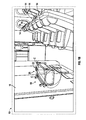
Fig. 1A is a schematic illustration of a mobile platform, such as an aircraft, that includes a bassinet including an illumination system in accordance with various embodiments; -
Fig. 1B is a schematic illustration of a mobile platform, such as an aircraft, that includes the bassinet including an illumination system in which the illumination system is illuminated, in accordance with various embodiments; -
Fig. 2 is a perspective view of the bassinet and illumination system ofFig. 1B ; -
Fig. 3 is a perspective view of the illumination system ofFig. 2 ; -
Fig. 4 is an exploded view of the illumination system ofFig. 2 ; -
Fig. 5 is a cross-sectional view of the illumination system ofFig. 2 , taken along line 5-5 ofFig. 2 ; -
Fig. 6 is a dataflow diagram illustrating a control system of the illumination system in accordance with various embodiments; and -
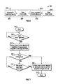
Fig. 7 is a flowchart illustrating a control method of the illumination system in accordance with various embodiments. - The following detailed description is merely exemplary in nature and is not intended to limit the application and uses. Furthermore, there is no intention to be bound by any expressed or implied theory presented in the preceding technical field, background, brief summary or the following detailed description. As used herein, the term module refers to any hardware, software, firmware, electronic control component, processing logic, and/or processor device, individually or in any combination, including without limitation: application specific integrated circuit (ASIC), an electronic circuit, a processor (shared, dedicated, or group) and memory that executes one or more software or firmware programs, a combinational logic circuit, and/or other suitable components that provide the described functionality.
- With reference to
Figs. 1A and1B , a mobile platform, such as anaircraft 10, is shown. It should be noted that while anaircraft 10 is described and illustrated herein, the present teachings are applicable to any suitable mobile platform, including, but not limited to, a ship, train, bus, car, etc. In one example, theaircraft 10 includes a passenger cabin 12. The passenger cabin 12 generally includes one ormore seats 14, and may include one ormore monuments 16. Themonuments 16 include, but are not limited to, toilet monuments, kitchen or galley monuments, partitions, class dividers, etc., as known to one skilled in the art. In one example, the passenger cabin 12 includes abassinet system 18. While thebassinet system 18 is illustrated herein as being coupled to themonument 16, thebassinet system 18 may be coupled to any suitable portion of the passenger cabin 12, such as one of theseats 14, for example. Thus, the illustration herein is merely exemplary. - The
bassinet system 18 includes abassinet 20 and anillumination system 22. It should be noted that the illustration of thebassinet 20 herein is merely exemplary, as the bassinet may have any suitable configuration and shape for receiving an infant. In one embodiment, with reference toFig. 2 , thebassinet 20 includes a plurality of sides generally indicated as 24 and a first orbottom surface 26 that cooperate to define acavity 28 for receipt of an infant. In one example, the plurality ofsides 24 andbottom surface 26 are formed by a first ortop rail 30, one or more second orbottom rails 32 and asupport structure 34. It should be noted that although not illustrated herein, thebassinet 20 may include a retaining flap that extends across a top surface of the cavity 28 (e.g. from a top surface of a first side to a top surface of a second side opposite the first side) to aid in restraining the infant within thecavity 28. Generally, the retaining flap extends across thecavity 28 to be substantially perpendicular to a longitudinal axis of thebassinet 20. The retaining flap is movable relative to thecavity 28 to enable unobstructed access to thecavity 28, and thus, the retaining flap generally would not obstruct light output by theillumination system 22 when theillumination system 22 is in use to illuminate thecavity 28. - In this example, the
top rail 30 extends around a perimeter of thebassinet 20 and defines a substantially rectangular shape. Thus, thetop rail 30 defines a perimeter for thecavity 28 that receives the infant. Thetop rail 30 may be cylindrical, and thus, thetop rail 30 may have a curved surface. Thetop rail 30 includes at least one mountingpoint 36 and one or more coupling points 38. The at least one mountingpoint 36, in one example, comprises two mountingpoints bassinet 20 to themonument 16. It should be noted that the mountingpoints bassinet 20 in the passenger cabin 12. - The one or more coupling points 38 couple the one or more
bottom rails 32 to thetop rail 30. In one example, the coupling points 38 comprise extensions that project outwardly or downwardly from thetop rail 30 and include a suitable fastening mechanism, such as a bore, for receipt of a fastener to couple thetop rail 30 to the one or more bottom rails 32. The coupling points 38 may have a reduced diameter to facilitate the receipt of a respective one of the coupling points 38 in a respective end of one of the one or more bottom rails 32. The one or morebottom rails 32 may each be substantially U-shaped, and may include ends sized to receive the one or more coupling points 38. The ends may include one or more bores through which a suitable fastening mechanism is received, such-as a bolt, for example. - In this example, the
support structure 34 generally defines the plurality ofsides 24,bottom surface 26 andcavity 28. Thesupport structure 34 includes one ormore pockets 40 along a top surface for coupling thesupport structure 34 to thetop rail 30. In other words, thetop rail 30 may be received in the one or more pockets 40. Thesupport structure 34 has sufficient rigidity to define thecavity 28, and may be comprised of a suitable material, such as a fabric. A bottom surface of thesupport structure 34 may be further supported on the one or more bottom rails 32. - The
illumination system 22 is coupled to thebassinet 20. It should be noted that while theilluminations system 22 is described and illustrated herein as being coupled to thebassinet 20, theillumination system 22 may be coupled to any desired structure, such as shelving, for example. Theillumination system 22 outputs light or light cones C, which are directed into thebassinet 20 to illuminate thebassinet 20, and an infant in thebassinet 20, to facilitate attending to the needs of the infant in thebassinet 20. In one embodiment, with reference toFigs. 3 and4 , theillumination system 22 includes ahousing 50, at least onelight source 52, auser input device 54, a power source 56 (Fig. 4 ) and a control module 58 (Fig. 4 ). Thepower source 56 may be, for example, a battery or the like. Theuser input device 54 may be, for example, a switch or the like. - The at least one
light source 52,user input device 54, power source 56 (Fig. 4 ) and control module 58 (Fig. 4 ) are at least partially received within thehousing 50. Thehousing 50 is coupled to thebassinet 20. In one example, thehousing 50 is coupled to thetop rail 30 of the bassinet 20 (Fig. 2 ), and may be coupled to thetop rail 30 at any desired position on thetop rail 30. Thehousing 50 is composed of any suitable material, such as a metal, metal alloy or polymer. In one example, thehousing 50 is composed of a polymer. Thehousing 50 may have a clamshell design, and includes afirst housing part 60 and asecond housing part 62 that cooperate to define a cavity 63 (Fig. 5 ) to at least partially house or contain the at least onelight source 52,user input device 54, power source 56 (Fig. 4 ) and control module 58 (Fig. 4 ). Thehousing 50 extends along a longitudinal axis L (Fig. 3 ). - With reference to
Fig. 4 , thefirst housing part 60 includes afirst surface 64, afirst side 66 and asecond side 68. Thefirst surface 64 includes afirst end 70, asecond end 72, auser input aperture 74 and abattery access aperture 76. In one example, thefirst surface 64 tapers at thefirst end 70 andsecond end 72, however, thefirst surface 64 may have any desired shape. Theuser input aperture 74 is near thefirst end 70, and is sized to enable a user to access theuser input device 54, and may allow a portion of theuser input device 54 to extend therethrough. In one example, theuser input aperture 74 is substantially annular; however, theuser input aperture 74 may have any desired shape. Thebattery access aperture 76 is positioned between theuser input aperture 74 and thesecond end 72. Thebattery access aperture 76 is substantially annular and may be sized to receive a correspondingly shapedbattery cap 78. In one example, thebattery access aperture 76 includes a lockingthread 80, which cooperates with a lockingthread 82 formed about a circumference of thebattery cap 78. The cooperation between the lockingthreads battery cap 78 to thefirst housing part 60 to provide access to thepower source 56. - The
first side 66 of thefirst housing part 60 is substantially opposite thesecond side 68. Thefirst side 66 includes at least onelight source aperture 84 to enable light output from the at least onelight source 52 to be projected or directed out of thefirst housing part 60. In one example, thefirst side 66 includes a firstlight source aperture 84a and a secondlight source aperture 84b. The firstlight source aperture 84a is generally spaced apart from the secondlight source aperture 84b along the longitudinal axis L of thehousing 50. - The
second housing part 62 mates with thefirst housing part 60. Thesecond housing part 62 includes afirst side 86 opposite asecond side 88, and asecond surface 90. Thesecond surface 90 is curved, and in one example, is concave between thefirst side 86 andsecond side 88, as illustrated inFig. 5 . Generally, the radius of curvature of thesecond surface 90 corresponds to the radius curvature of the top surface of thetop rail 30, to facilitate coupling thehousing 50 on thetop rail 30. With reference back toFig. 4 , thesecond surface 90 also includes at least one coupling aperture 92, and in one example, includes twocoupling apertures coupling apertures fastener 93 to couple thehousing 50 to thetop rail 30. In this example, thetop rail 30 includes two apertures through which a respective one of thefasteners 93 are received. Thefasteners 93 are threaded into engagement with the plurality of threads on thecoupling apertures housing 50 to thetop rail 30. In addition, thefasteners 93 may be received in corresponding apertures defined in a portion of thefirst housing part 60 to further couple thefirst housing part 60 to thesecond housing part 62, if desired. - With continued reference to
Fig. 4 , at least onelight source 52 outputs the at least one light or light cone C (Fig. 2 ) from theillumination system 22. In one example, the at least onelight source 52 includes a firstlight source 52a and a secondlight source 52b, however, theillumination system 22 can include any number of light sources or a single light source, if desired. Thelight sources light sources light sources light sources control module 58 to receive power from thepower source 56 over a suitable architecture that facilitates the transfer of power and/or data, such as a carrier substrate orcircuit board 94, as known to those skilled in the art. In one example, thecircuit board 94 is coupled to thesecond housing part 62 via a mechanical fastener, such as ascrew 95. - The
user input device 54 in communication with thecontrol module 58, and receives input from an operator and generates data and/or signals based thereon. In one example, theuser input device 54 is mounted to thecircuit board 94, however, theuser input device 54 can be in communication with thecontrol module 58 via any suitable communication architecture. Theuser input device 54 is any suitable device capable of receiving user input, including, but not limited to, a switch, a button, a microphone, a touchscreen, or other suitable device to receive commands from the user. In one example, theuser input device 54 is a switch, and a portion of the switch extends through theuser input aperture 74 to enable the user to move, for example, depress and release, the switch. In this example, the movement of the switch generates data and/or signals for thecontrol module 58. It should be noted that theuser input device 54 is merely exemplary, as thecontrol module 58 can activate thelight sources bassinet 20 and/or pressure pad coupled to thesupport structure 34, for example. - The
power source 56 is in communication with thecontrol module 58 for supplying power to thelight sources power source 56 is mounted to thecircuit board 94; however, thepower source 56 can be in communication with thecontrol module 58 via any suitable architecture that facilitates the transfer of power and/or data. Thepower source 56 is any suitable device capable of supplying power, such as an electric current, including, but not limited to, one or more batteries. It should be noted that thepower source 56 described herein as being contained within thehousing 50 is merely exemplary, as the power source may be external or remote from thehousing 50, if desired. - In various embodiments, the
control module 58 controls the operation of thelight sources user input device 54 and further based on the illumination systems and methods of the present disclosure to illuminate at least a portion of thebassinet 20. As will be discussed, thecontrol module 58 outputs one or more signals to thelight sources light sources power source 56 based on the signals from theuser input device 54. It should be noted that thecontrol module 58 is in communication with thepower source 56 anduser input device 54 over a suitable architecture that allows the transfer of data and/or power, such as thecircuit board 94. - Referring now to
Fig. 6 , and with continued reference toFigs. 1A-5 , a dataflow diagram illustrates various embodiments of anillumination control system 200 for the illumination system 22 (Figs. 1A and1B ) that may be embedded within thecontrol module 58. Various embodiments of the illumination control system according to the present disclosure can include any number of sub-modules embedded within thecontrol module 58. As can be appreciated, the sub-modules shown inFig. 6 can be combined and/or further partitioned to similarly control the output of thelight sources Fig. 4 ). Inputs to the system can be sensed from the aircraft 10 (Figs. 1A and1B ), received from other control modules (not shown), and/or determined/modeled by other sub-modules (not shown) within thecontrol module 58. In various embodiments, thecontrol module 58 includes a userinterface control module 202 and anillumination control module 204. - The user
interface control module 202 receives as inputuser input data 206 based on a user's interaction with theuser input device 54. In one example, theuser input data 206 comprises a request to activate or deactivate thelight sources user input data 206, the userinterface control module 202 sets theuser input data 206 for theillumination control module 202. - The
illumination control module 202 receives as inputuser input data 206. Theillumination control module 202 generates one ormore signals 208 to supply power from thepower source 56 to thelight sources user input data 206. In various embodiments, theillumination control module 202 varies the amount of power supplied by thepower source 56 based on a time period associated with the receipt of theuser input data 206. In one example, the one ormore signals 208 are generated to supply power to thelight sources user input data 206. The predefined time period is about five minutes, however, the predefined time period may be about ten minutes. - Referring now to
Fig. 7 , and with continued reference toFigs. 1A-6 , a flowchart illustrates a control method that can be performed by the control module 58 (Fig. 4 ) in accordance with the present disclosure. As can be appreciated in light of the disclosure, the order of operation within the method is not limited to the sequential execution as illustrated inFig. 7 , but may be performed in one or more varying orders as applicable and in accordance with the present disclosure. - The method begins at 300. At 302, the method determines if
user input data 206 has been received from the user's interaction with theuser input device 54. Ifuser input data 206 is received, the method goes to 304. Otherwise, the method loops. - At 304, the method outputs one or
more signals 208 to supply thelight sources more signals 208 to ramp or gradually increase the power supplied from an initial starting power supply to a maximum power supply such that the light output from thelight sources user input data 206 was received is greater than a predefined threshold time T. The predefined threshold time T is about five minutes, for example. If the time t since theuser input data 206 was received is greater than the predefined threshold time T, the method goes to 308. Otherwise, at 310, the method determines if additionaluser input data 206 has been received from the user's interaction with theuser input device 54. Ifuser input data 206 is received, the method goes to 308. Otherwise, the method loops to 306. - At 308, the method outputs one or
more signals 208 to remove the power from thelight sources more signals 208 to gradually reduce the supply of power to thelight sources light sources - While at least one exemplary embodiment has been presented in the foregoing detailed description, it should be appreciated that a vast number of variations exist. It should also be appreciated that the exemplary embodiment or exemplary embodiments are only examples, and are not intended to limit the scope, applicability, or configuration of the disclosure in any way. Rather, the foregoing detailed description will provide those skilled in the art with a convenient road map for implementing the exemplary embodiment or exemplary embodiments. It should be understood that various changes can be made in the function and arrangement of elements without departing from the scope of the appended claims and the legal equivalents thereof.
Claims (15)
- An illumination system (22) for a bassinet (20) of a mobile platform, comprising:a housing (50) including a first housing part (60) defining at least one aperture (84) and a second housing part (62) coupled to the first housing part (60) so as to define a housing cavity (63);at least one light source (52) disposed within the housing cavity (63) and adjacent to the at least one aperture (84) such that light output by the at least one light source (52) is directed out of the first housing part (60);a user input device (54) coupled to the housing (50) that receives user input;a power source (56); anda control module (58) that supplies power from the power source (56) to the at least one light source (52) to illuminate the bassinet (20) based on the user input.
- The system (22) of Claim 1, wherein the second housing part (62) is directly coupled to the bassinet (20).
- The system (22) of Claim 1, wherein the at least one light source (52) comprises a first light source (52a) and a second light source (52b), and the first light source (52a) is spaced apart from the second light source (52b) along a longitudinal axis (L) of the housing (50).
- The system (22) of Claim 3, wherein the at least one aperture (84) comprises a first aperture (84a) and a second aperture (84b), and the first light source (52a) is adjacent to the first aperture (84a) and the second light source (52b) is adjacent to the second light aperture (84b).
- The system (22) of Claim 1, wherein the first housing part (60) includes a first surface (64) and a first side (66) opposite a second side (68), and the at least one aperture (84) is defined in the first side (66).
- The system (22) of Claim 5, wherein the first surface (64) of the first housing part (60) includes a user input aperture (74), and a portion of the user input device (54) is accessible through the user input aperture (74).
- The system (22) of Claim 1, wherein the power source (56) is disposed in the housing cavity (63).
- The system (22) of Claim 1, wherein the control module (58) gradually supplies power to the at least one light source (52).
- A bassinet (20) for a mobile platform, comprising:a first rail (30) that defines a perimeter of a cavity (28), the first rail (30) adapted to be coupled to the mobile platform;a support structure (34) coupled to the first rail (30) that defines a plurality of sides (24) and the cavity (28);a housing (50) that defines a housing cavity (63) and includes a first aperture (84a) spaced apart from a second aperture (84b) along a longitudinal axis (L) of the housing (50), the housing (50) directly coupled to the first rail (30);a first light source (52a) disposed within the housing cavity (63) adjacent to the first aperture (84a) such that light output by the first light source (52a) is directed out of the housing (50);a second light source (52b) disposed within the housing cavity (63) adjacent to the second aperture (84b) such that light output by the second light source (52b) is directed out of the housing (50);a power source (56); anda control module (58) that supplies power from the power source (56) to the first light source (52a) and second light source (52b) to illuminate the cavity (28).
- The bassinet (20) of Claim 9, further comprising:a user input device (54) that receives user input,wherein the control module (58) supplies power from the power source (56) to the first light source (52a) and second light source (52b) based on the user input.
- The bassinet (20) of Claim 9, wherein the housing (50) comprises a first housing part (60) and a second housing part (62) that cooperate to define the housing cavity (63), and the first aperture (84a) and the second aperture (84b) are defined in the first housing part (60).
- The bassinet (20) of Claim 11, wherein the second housing part (62) comprises a first side (86) opposite a second side (88) and a surface (90) that extends between the first side (86) and the second side (88), the surface (90) curved to correspond with a curvature of the first rail (30).
- The bassinet (20) of Claim 10, wherein the control module (58) gradually supplies power to the first light source (52a) and second light source (52b) based on the user input.
- An aircraft (10), comprising:a bassinet (20) having a plurality of sides (24) and a surface (26) that cooperate to define a cavity (28), the plurality of sides (24) forming a perimeter of the cavity (28);an illumination system (22) coupled to the perimeter of the bassinet (20), the illumination system (22) including:a housing (50) including a first housing part (60) defining at least one aperture (84) and a second housing part (62) coupled to the first housing part (60) so as to define a housing cavity (63), the second housing part (62) coupled to the perimeter of the bassinet (20);at least one light source (52) disposed within the housing cavity (63) and adjacent to the at least one aperture (84) such that light output by the at least one light source (52) is directed out of the first housing part (60);a user input device (54) coupled to the housing (50) that receives user input;a power source (56) disposed within the housing cavity (63); anda control module (58) that supplies power from the power source (56) to the at least one light source (52) to illuminate the cavity (28) of the bassinet (20) based on the user input.
- The aircraft (10) of Claim 14, wherein the control module (58) gradually decreases the supply of power from the power source (56) to the at least one light source (52) based on a time (t) since the receipt of user input exceeding a predefined threshold time (T).
Applications Claiming Priority (1)
| Application Number | Priority Date | Filing Date | Title |
|---|---|---|---|
| US14/288,031 US20150345778A1 (en) | 2014-05-27 | 2014-05-27 | Bassinet illumination system |
Publications (1)
| Publication Number | Publication Date |
|---|---|
| EP2949576A1 true EP2949576A1 (en) | 2015-12-02 |
Family
ID=53189558
Family Applications (1)
| Application Number | Title | Priority Date | Filing Date |
|---|---|---|---|
| EP15001431.4A Withdrawn EP2949576A1 (en) | 2014-05-27 | 2015-05-13 | Bassinet with illumination system |
Country Status (2)
| Country | Link |
|---|---|
| US (1) | US20150345778A1 (en) |
| EP (1) | EP2949576A1 (en) |
Families Citing this family (5)
| Publication number | Priority date | Publication date | Assignee | Title |
|---|---|---|---|---|
| CN107985154B (en) * | 2017-12-25 | 2024-03-26 | 长安大学 | Carriage sliding type baby cradle device |
| US11492122B2 (en) | 2020-01-13 | 2022-11-08 | B/E Aerospace, Inc. | Adapter plate for an aircraft seat |
| EP4541716A1 (en) | 2023-10-16 | 2025-04-23 | B/E Aerospace, Inc. | Multi location foldable bassinet |
| US12557920B2 (en) * | 2023-10-16 | 2026-02-24 | B/E Aerospace, Inc. | Multi location foldable bassinet |
| EP4549317A1 (en) * | 2023-11-02 | 2025-05-07 | B/E Aerospace, Inc. | Passenger compartment for a cabin of an aircraft |
Citations (4)
| Publication number | Priority date | Publication date | Assignee | Title |
|---|---|---|---|---|
| DE20202465U1 (en) * | 2002-02-18 | 2002-08-08 | Liaw, Shu-Jang, Taichung | warning light |
| US20100107331A1 (en) * | 2007-04-16 | 2010-05-06 | Gilles Negre | Cradle adaptable to an aircraft seat |
| US20110058359A1 (en) * | 2009-09-04 | 2011-03-10 | Keiji Taiga | Outdoor use illumination device |
| US20110157874A1 (en) * | 2008-09-10 | 2011-06-30 | Eveready Battery Company, Inc. | Attachable Portable Lighting Device and Methods of Operation |
Family Cites Families (22)
| Publication number | Priority date | Publication date | Assignee | Title |
|---|---|---|---|---|
| US2276370A (en) * | 1939-06-05 | 1942-03-17 | Johannes Rose | Illuminating device for portable receptacles |
| US3609342A (en) * | 1969-12-10 | 1971-09-28 | Maria Wisniewski | Light for ladies handbag |
| US3764976A (en) * | 1971-06-14 | 1973-10-09 | Kimball A | Pedal mounted signal light |
| CA924693A (en) * | 1972-01-26 | 1973-04-17 | A. Caron Joseph | Porte-clefs lumineux |
| US4742438A (en) * | 1987-03-05 | 1988-05-03 | Lumenaries, Inc. | Purse light |
| US5018057A (en) * | 1990-01-17 | 1991-05-21 | Lamp Technologies, Inc. | Touch initiated light module |
| JP4061347B2 (en) * | 2003-08-05 | 2008-03-19 | 株式会社キャットアイ | Lighting device |
| JP2005153596A (en) * | 2003-11-21 | 2005-06-16 | Cateye Co Ltd | Mounting device |
| US6979099B2 (en) * | 2004-02-12 | 2005-12-27 | Brookstone Purchasing, Inc. | Portable lighting device with multi-activation switch |
| US20060203473A1 (en) * | 2005-03-14 | 2006-09-14 | Chih-Yuan Hsueh | Portable illuminator with mirror |
| JP4173499B2 (en) * | 2005-06-17 | 2008-10-29 | 株式会社シマノ | Bicycle lighting device |
| CA2585627A1 (en) * | 2006-04-20 | 2007-10-20 | The Flewelling Ford Family Trust | Mounting support with light |
| US7942553B2 (en) * | 2008-01-25 | 2011-05-17 | Eveready Battery Company, Inc. | Lighting device and optics package therefor |
| US20090290331A1 (en) * | 2008-05-20 | 2009-11-26 | Jacobs Robert J | Illuminating apparatus |
| US8529086B2 (en) * | 2010-02-23 | 2013-09-10 | Black Diamond Equipment Ltd. | Systems and methods for locking a portable illumination system |
| US8382309B1 (en) * | 2011-02-01 | 2013-02-26 | David Johnston | Light pod system |
| US9101190B2 (en) * | 2011-07-21 | 2015-08-11 | Custom LeatherCraft Manufacturing Company, Inc. | Handle light |
| US20130021786A1 (en) * | 2011-07-21 | 2013-01-24 | Noble Matthew D | Utility bag lighting |
| DK201100777A (en) * | 2011-10-07 | 2013-04-08 | Beck Lars | Cykellygte |
| US20130141933A1 (en) * | 2011-12-06 | 2013-06-06 | Nova Sport Lights, Llc | Pivotable led lighting apparatus and universal mounting assembly and method |
| US9204699B2 (en) * | 2013-05-02 | 2015-12-08 | Custom Leathercraft Manuf, Co., Inc. | Roller bag handle with lighting |
| JP6184759B2 (en) * | 2013-06-04 | 2017-08-23 | 株式会社キャットアイ | Bicycle light |
-
2014
- 2014-05-27 US US14/288,031 patent/US20150345778A1/en not_active Abandoned
-
2015
- 2015-05-13 EP EP15001431.4A patent/EP2949576A1/en not_active Withdrawn
Patent Citations (4)
| Publication number | Priority date | Publication date | Assignee | Title |
|---|---|---|---|---|
| DE20202465U1 (en) * | 2002-02-18 | 2002-08-08 | Liaw, Shu-Jang, Taichung | warning light |
| US20100107331A1 (en) * | 2007-04-16 | 2010-05-06 | Gilles Negre | Cradle adaptable to an aircraft seat |
| US20110157874A1 (en) * | 2008-09-10 | 2011-06-30 | Eveready Battery Company, Inc. | Attachable Portable Lighting Device and Methods of Operation |
| US20110058359A1 (en) * | 2009-09-04 | 2011-03-10 | Keiji Taiga | Outdoor use illumination device |
Also Published As
| Publication number | Publication date |
|---|---|
| US20150345778A1 (en) | 2015-12-03 |
Similar Documents
| Publication | Publication Date | Title |
|---|---|---|
| EP2949576A1 (en) | Bassinet with illumination system | |
| US20130343072A1 (en) | Individual lighting device for a vehicle seat | |
| CN104760704B (en) | Method and system for detecting attachment of a gyrocopter tie down | |
| US20110163697A1 (en) | Cabin illuminating device of aircraft | |
| US11760488B2 (en) | Seat assembly having integrated lighting system | |
| US9211953B2 (en) | Equipment module for a vehicle and vehicle with a vehicle body comprising a cargo space | |
| US10800529B2 (en) | Passenger supply unit for an aircraft cabin | |
| CN111746809A (en) | Camera module and system for monitoring a passenger cabin of an aircraft, and aircraft | |
| WO2006036214A3 (en) | Vtol aircraft external load drag reduction system | |
| EP3718893B1 (en) | Component positioning systems and methods for an internal cabin of vehicle | |
| WO2010051957A3 (en) | Overhead reading light for a passenger seat | |
| US20150077556A1 (en) | Vehicle system for automated video recording | |
| EP1010617A3 (en) | Overhead accomodations for aircraft | |
| US20230225515A1 (en) | Illuminated seat panel | |
| WO2018020017A3 (en) | Child car seat for attaching to a motor vehicle | |
| EP2990334A1 (en) | Separating device for separating two zones of a passenger cabin equipped with overhead luggage bins comprising a movable shell | |
| EP3305659B1 (en) | Methods and devices for light distribution in an aircraft, and aircraft including such devices | |
| CN110386101A (en) | Seat-assembly, safety belt security ststem and method | |
| EP2679447A3 (en) | Systems and methods for disabling a vehicle horn | |
| EP2883793A2 (en) | Luggage system having a component installation space | |
| CN109155379A (en) | battery fastening system and method | |
| US20140239807A1 (en) | Deceleration-Triggered LED Stop Lamp | |
| WO2017078823A3 (en) | Modular autopilot design and development featuring bayesian non-parametric adaptive control | |
| US9315272B2 (en) | System and method for cooling and/or heating aircraft devices | |
| US20130340749A1 (en) | Passenger reading light integrated in psu/emergency oxygen device |
Legal Events
| Date | Code | Title | Description |
|---|---|---|---|
| AK | Designated contracting states |
Kind code of ref document: A1 Designated state(s): AL AT BE BG CH CY CZ DE DK EE ES FI FR GB GR HR HU IE IS IT LI LT LU LV MC MK MT NL NO PL PT RO RS SE SI SK SM TR |
|
| AX | Request for extension of the european patent |
Extension state: BA ME |
|
| PUAI | Public reference made under article 153(3) epc to a published international application that has entered the european phase |
Free format text: ORIGINAL CODE: 0009012 |
|
| 17P | Request for examination filed |
Effective date: 20160602 |
|
| RBV | Designated contracting states (corrected) |
Designated state(s): AL AT BE BG CH CY CZ DE DK EE ES FI FR GB GR HR HU IE IS IT LI LT LU LV MC MK MT NL NO PL PT RO RS SE SI SK SM TR |
|
| 17Q | First examination report despatched |
Effective date: 20161212 |
|
| STAA | Information on the status of an ep patent application or granted ep patent |
Free format text: STATUS: THE APPLICATION HAS BEEN WITHDRAWN |
|
| 18W | Application withdrawn |
Effective date: 20170413 |