EP2949249A1 - Pulse shower device - Google Patents
Pulse shower device Download PDFInfo
- Publication number
- EP2949249A1 EP2949249A1 EP14743143.1A EP14743143A EP2949249A1 EP 2949249 A1 EP2949249 A1 EP 2949249A1 EP 14743143 A EP14743143 A EP 14743143A EP 2949249 A1 EP2949249 A1 EP 2949249A1
- Authority
- EP
- European Patent Office
- Prior art keywords
- shower
- impeller
- holes
- portions
- water
- Prior art date
- Legal status (The legal status is an assumption and is not a legal conclusion. Google has not performed a legal analysis and makes no representation as to the accuracy of the status listed.)
- Granted
Links
Images







Classifications
-
- B—PERFORMING OPERATIONS; TRANSPORTING
- B05—SPRAYING OR ATOMISING IN GENERAL; APPLYING FLUENT MATERIALS TO SURFACES, IN GENERAL
- B05B—SPRAYING APPARATUS; ATOMISING APPARATUS; NOZZLES
- B05B1/00—Nozzles, spray heads or other outlets, with or without auxiliary devices such as valves, heating means
- B05B1/14—Nozzles, spray heads or other outlets, with or without auxiliary devices such as valves, heating means with multiple outlet openings; with strainers in or outside the outlet opening
- B05B1/18—Roses; Shower heads
- B05B1/185—Roses; Shower heads characterised by their outlet element; Mounting arrangements therefor
-
- B—PERFORMING OPERATIONS; TRANSPORTING
- B05—SPRAYING OR ATOMISING IN GENERAL; APPLYING FLUENT MATERIALS TO SURFACES, IN GENERAL
- B05B—SPRAYING APPARATUS; ATOMISING APPARATUS; NOZZLES
- B05B1/00—Nozzles, spray heads or other outlets, with or without auxiliary devices such as valves, heating means
- B05B1/02—Nozzles, spray heads or other outlets, with or without auxiliary devices such as valves, heating means designed to produce a jet, spray, or other discharge of particular shape or nature, e.g. in single drops, or having an outlet of particular shape
- B05B1/08—Nozzles, spray heads or other outlets, with or without auxiliary devices such as valves, heating means designed to produce a jet, spray, or other discharge of particular shape or nature, e.g. in single drops, or having an outlet of particular shape of pulsating nature, e.g. delivering liquid in successive separate quantities
- B05B1/083—Nozzles, spray heads or other outlets, with or without auxiliary devices such as valves, heating means designed to produce a jet, spray, or other discharge of particular shape or nature, e.g. in single drops, or having an outlet of particular shape of pulsating nature, e.g. delivering liquid in successive separate quantities the pulsating mechanism comprising movable parts
-
- B—PERFORMING OPERATIONS; TRANSPORTING
- B05—SPRAYING OR ATOMISING IN GENERAL; APPLYING FLUENT MATERIALS TO SURFACES, IN GENERAL
- B05B—SPRAYING APPARATUS; ATOMISING APPARATUS; NOZZLES
- B05B1/00—Nozzles, spray heads or other outlets, with or without auxiliary devices such as valves, heating means
- B05B1/02—Nozzles, spray heads or other outlets, with or without auxiliary devices such as valves, heating means designed to produce a jet, spray, or other discharge of particular shape or nature, e.g. in single drops, or having an outlet of particular shape
- B05B1/08—Nozzles, spray heads or other outlets, with or without auxiliary devices such as valves, heating means designed to produce a jet, spray, or other discharge of particular shape or nature, e.g. in single drops, or having an outlet of particular shape of pulsating nature, e.g. delivering liquid in successive separate quantities
- B05B1/083—Nozzles, spray heads or other outlets, with or without auxiliary devices such as valves, heating means designed to produce a jet, spray, or other discharge of particular shape or nature, e.g. in single drops, or having an outlet of particular shape of pulsating nature, e.g. delivering liquid in successive separate quantities the pulsating mechanism comprising movable parts
- B05B1/085—Nozzles, spray heads or other outlets, with or without auxiliary devices such as valves, heating means designed to produce a jet, spray, or other discharge of particular shape or nature, e.g. in single drops, or having an outlet of particular shape of pulsating nature, e.g. delivering liquid in successive separate quantities the pulsating mechanism comprising movable parts rotated by the liquid or other fluent material discharged, e.g. liquid rotated turbines
-
- B—PERFORMING OPERATIONS; TRANSPORTING
- B05—SPRAYING OR ATOMISING IN GENERAL; APPLYING FLUENT MATERIALS TO SURFACES, IN GENERAL
- B05B—SPRAYING APPARATUS; ATOMISING APPARATUS; NOZZLES
- B05B1/00—Nozzles, spray heads or other outlets, with or without auxiliary devices such as valves, heating means
- B05B1/14—Nozzles, spray heads or other outlets, with or without auxiliary devices such as valves, heating means with multiple outlet openings; with strainers in or outside the outlet opening
- B05B1/18—Roses; Shower heads
-
- B—PERFORMING OPERATIONS; TRANSPORTING
- B05—SPRAYING OR ATOMISING IN GENERAL; APPLYING FLUENT MATERIALS TO SURFACES, IN GENERAL
- B05B—SPRAYING APPARATUS; ATOMISING APPARATUS; NOZZLES
- B05B3/00—Spraying or sprinkling apparatus with moving outlet elements or moving deflecting elements
- B05B3/02—Spraying or sprinkling apparatus with moving outlet elements or moving deflecting elements with rotating elements
- B05B3/04—Spraying or sprinkling apparatus with moving outlet elements or moving deflecting elements with rotating elements driven by the liquid or other fluent material discharged, e.g. the liquid actuating a motor before passing to the outlet
Definitions
- the present invention relates to a pulse shower device that intermittently discharges water in pulses from shower holes.
- pulse shower devices which intermittently discharge water in pulses from shower holes by intermittently blocking and opening the shower holes, are well-known.
- General pulse shower devices include a water dispersion plate including a plurality of shower holes that are provided from an inner surface to an outer surface, and an impeller that is provided on an upstream side of the inner surface of the water dispersion plate and rotates around an axis due to a water stream hitting vanes.
- the impeller includes, alternately in the circumferential direction, a shower hole blocking portion that extends over a predetermined circumferential length along the inner surface of the water dispersion plate in a downstream portion of an inner surface portion of the water dispersion plate and covers the shower holes, and a shower hole opening portion that opens toward the inner surface of the water dispersion plate.
- the shower hole blocking portion and the shower hole opening portion are rotationally moved around the axis through the rotation of the impeller, the shower holes are intermittently blocked and opened, and water is intermittently discharged in pulses from the shower holes.
- Patent Document 1 discloses a shower head including a cap (water dispersion plate) 70 having jet holes (shower holes) 74, and an impeller 56 on an upstream side of the cap.
- the impeller 56 includes a cover plate 60 as a shower hole blocking portion over a semicircle, and a shower hole opening portion over the remaining semicircle.
- the impeller 56 is rotationally moved by the action of a water stream to vanes 57, the cover plate 60 as the shower hole blocking portion and the shower hole opening portion are rotationally driven around an axis, the shower holes are intermittently blocked and opened, and water is intermittently discharged in pulses.
- Patent Document 2 discloses a water discharge device including a water dispersion plate 58 having shower holes 118, and an impeller 124 on an upstream side of the cover dispersion plate.
- the impeller 124 includes a shower hole blocking portion 130 over a semicircle, and a shower hole opening portion over the remaining semicircle.
- the shower hole blocking portion 130 and the shower hole opening portion are rotationally moved around an axis through the rotation of the impeller 124, the shower holes 118 are intermittently blocked and opened, and water is intermittently discharged in pulses.
- a portion used as the water dispersion plate of a pulse shower device (device that intermittently discharges water through the rotation of the impeller) is only a portion on the inner peripheral side of the entire water dispersion plate of the shower head, the water dispersion plate (specifically, the portion used as the shower device in detail) and the impeller have smaller diameters, and the pulse shower device itself is small-sized.
- the impeller is made to have a larger diameter with an increase in the diameter of the water dispersion plate, and thereby, when the pulse shower device is enlarged, a sensation while showering in water deteriorates if the shape of the small (small-diameter) impeller is merely made large (made to have a larger diameter) as it is.
- a user feels that showering in a shower has worsened. Specifically, a pulsating sensation of the water that is intermittently discharged becomes strong.
- a small-sized pulse shower device 205A includes a small-diameter impeller 200A, a shower hole blocking portion 202A and a shower hole opening portion 204A that are provided in the impeller 200A, and water spray holes 206 provided in a water dispersion plate.
- a larger-diameter impeller 200B in a large-sized pulse shower device 205B, includes a shower hole blocking portion 202B and a shower hole opening portion 204B that are provided in the impeller 200B, and water spray holes 206 provided in a water dispersion plate.
- shower holes 206a that are in a blocked state due to the shower hole blocking portion 202A.
- shower holes 206a of the inner peripheral portion of the large-sized pulse shower device 205B is the time for which the shower holes are brought into the blocked state by the shower hole blocking portion 202B is t 1 seconds, and the time for which the shower holes are brought into the open state by the shower hole opening portion 204B is t 2 seconds.
- the circumferential length of the outer peripheral portion of the shower hole blocking portion 202B that acts to block the shower holes 206b and 206c is greater than the circumferential length of the shower hole blocking portion 202A in the small-sized pulse shower device 205A. Nevertheless, the time for which the shower holes are brought into the blocked state by the shower hole blocking portion 204B is t 1 seconds, and the time for which the shower holes are brought into the open state by the shower hole opening portion 204B is t 2 seconds. That is, this is the same as in the case of the shower holes 206a.
- both of the rotational frequency of the impeller 200A of the small-sized pulse shower device 205A and the rotational frequency of the impeller 200B of the large-sized pulse shower device 205B are both n 1 , only the circumferential speed of the portion on the outer peripheral side of the shower hole blocking portion 202B becomes faster than the circumferential speed of the shower hole blocking portion 202A, but the rotating speeds (the rotational frequencies) are the same. Therefore, the time interval it takes until the shower holes are brought into the open state from the blocked state and brought into the blocked state from the open state are the same not only in the shower hole 206a but also in the shower holes 206b and 206c.
- a user feels that the time interval taken until the water is switched from being blocked to being able to flow freely and from being able to flow freely to being blocked is physically felt as being longer, a pulsating sensation is strong, and a user's sensation while showering in water deteriorates.
- the invention has been made in view of the above circumstances, and provides a pulse shower device that intermittently discharges water, which can ensure an excellent showering feeling even in a case where the pulse shower device is enlarged.
- a pulse shower device including a water dispersion plate that includes an inner surface and an outer surface, and a plurality of shower holes that penetrate from the inner surface to the outer surface; and an impeller that includes a shower hole blocking portion that is formed over a predetermined circumferential length along the inner surface in a downstream portion of the inner surface of the water dispersion plate, and covers the plurality of shower holes; a shower hole opening portion that opens toward the inner surface; a plurality of vanes; an inner peripheral portion; and an outer peripheral portion, that is provided on an upstream portion of the inner surface of the water dispersion plate, and that rotates around an axis due to a water stream hitting the vanes.
- the shower hole blocking portion and the shower hole opening portion are alternately arranged in a circumferential direction on the same circumference, and rotate around the axis through the rotation of the impeller to intermittently block and open the shower holes, and intermittently discharge water in pulses from the shower holes.
- the number of shower hole blocking portions and shower hole opening portions that are arranged on the same circumference at the outer peripheral portion is greater than the number of shower hole blocking portions and shower hole opening portions at the inner peripheral portion, and a time interval from the blocking of the shower holes at the outer peripheral portion to the closing thereof and from the opening thereof to the blocking thereof is shorter than a time interval from the blocking of the shower holes at the inner peripheral portion to the closing thereof and from the opening thereof to the blocking thereof.
- the ratio of the circumferential length of the shower hole blocking portion and the shower hole opening portion arranged on the same circumference to the whole circumferential length is smaller at the outer peripheral portion than the inner peripheral portion.
- the ratio of the circumferential length of the shower hole blocking portion and the shower hole opening portion arranged on the same circumference to the whole circumferential length is equal to or higher than 0.04.
- the pulse shower device that rotationally moves the shower hole blocking portion and the shower hole opening portion around the axis through the rotation of the impeller, intermittently blocks and opens the shower holes, and intermittently discharges water from the shower holes
- the number of shower hole blocking portions and shower hole opening portions that are arranged on the same circumference is greater at the outer peripheral portion than at the inner peripheral portion, and the time interval from the blocking of the shower holes at the outer peripheral portion to the closing thereof and from the opening thereof to the blocking thereof is shorter than the time interval at the inner peripheral portion.
- a pulsating sensation of water is relaxed even in a case where the pulse shower device is enlarged, and a sensation while showering in water is prevented from deteriorating due to an excessively strong pulsating sensation of the water. Accordingly, a user can be made to feel a comfortable sensation while showering in a shower.
- a shower head (pulse shower device) 10 includes a grip part 12, a head part 14, and a water dispersion plate 16 provided in the head part 14.
- a large number of shower holes 18 that penetrate from an inner surface to an outer surface (lower surface) are provided in the water dispersion plate 16 so as to form four concentric circles.
- shower holes 18-1 at the outermost periphery of the concentric circles, shower holes 18-2 further inwards from the shower holes 18-1, shower holes 18-3 further inwards thereof, and shower holes 18-4 at the innermost periphery thereof are respectively shown in the drawing.
- the internal structure of the head part 14 of the shower head 10 is specifically shown in FIG. 2 .
- the head part 14 of the shower head 10 has an upper case 20, and a cap 22 that is a lower case that closes an opening at a lower end (in the drawing) of the upper case 20.
- the upper case 20 has a cylindrical peripheral wall portion 24 that is provided with a female thread portion (not shown).
- the cap 22 has a cylindrical rising portion 26 that is provided with a male thread portion (not shown).
- the cap 22 is screw-coupled to the upper case 20 by the male thread portion and the female thread portion.
- the internal structure of the head part 14 is shown in detail in FIGS. 2 to 5 .
- a nozzle seat 28 As shown in FIGS. 2 , 4 , and 5 , a nozzle seat 28, a ring-shaped packing 30, an impeller unit 32, and a spiral flow generating member 34 are included inside the head part 14.
- the impeller unit 32 as shown in FIGS. 2 and 3 , has an impeller 36, and an impeller housing 38 that houses the impeller 36 therein.
- the impeller housing 38 is constituted of a main housing body 40 that serves as a nozzle seat retainer, and a lid body 42.
- the water dispersion plate 16 is configured to have a three-fold stacked structure of a bottom portion 44 of the cap 22, a seat portion 46 of the nozzle seat 28 superposed on the bottom portion 44, and a bottom portion 48 of the main housing body 40 further superposed on the seat portion 46.
- the nozzle seat 28 is made of rubber, the nozzle seal may be made of other elastomer materials.
- the nozzle seat 28 has the seat portion 46, and a plurality of nozzle portions 50 that protrude downward (downward direction in the drawing) from the seat portion 46.
- the respective nozzle portions 50 are inserted through insertion holes 52 formed in the bottom portion 44 of the cap 22 made of resin, and respective tip portions thereof protrude downward.
- the plurality of nozzle portions 50 have nozzle holes 18A therein, respectively, and lower portions of the shower holes 18 are formed by the nozzle holes 18A.
- the diameter of the nozzle holes 18A is ⁇ 0.8 mm.
- the seat portion 46 of the nozzle seat 28, as shown in FIGS. 3 and 4 has a curved shape such that a lower surface thereof in the drawing become convex downward and an upper surface thereof in the drawing becomes concave downward, and the respective nozzle portions 50 having a shape that falls perpendicularly from the lower surface of the seat portion 46 are integrally formed in the seat portion 46.
- a lower surface of the main housing body 40 that serves as the above nozzle retainer forms a convex surface corresponding to the concave surface of the seat portion 46 of the nozzle seat 28.
- a large number of communication holes 18B that communicates with the nozzle holes 18A and form upper portions of the shower holes 18 are provided in the bottom portion 48 of the main housing body 40 so as to pass through the bottom portion 48.
- a cylindrical portion 54 is provided at a central portion of the upper case 20, and a water channel forming member 56 that has a bottomed cylindrical shape and is made of resin is assembled into the cylindrical portion 54.
- a cylindrical portion 58 that rises upward at a central portion of the spiral flow generating member 34 is inserted into the cylindrical portion 54.
- An inflow chamber 62 into which the water from the water channel 60 is made to flow is formed inside the cylindrical portion 54 by the water channel forming member 56 and the cylindrical portion 58.
- the spiral flow generating member 34 inclines gently downward in an outer circumferential direction from the center thereof, and has an upper wall portion 64 that has a flat shape which widens in a direction perpendicular to an axis (axis-perpendicular direction) thereof, and a cylindrical peripheral wall portion 66 that falls downward at an outer peripheral end of the upper wall portion 64.
- a water chamber 68 configured to generate a spiral flow is formed between the upper wall portion 64 and the lid body 42 of the impeller housing 38.
- the spiral flow generating member 34 is provided with stationary vanes 70 that fall from the upper wall portion 64 and extend in a partial spiral shape from an inner peripheral end toward an outer peripheral end, and the stationary vanes 70 abut against an upper surface of the lid body 42 of the impeller housing 38.
- the spiral flow generating member 34 changes the flow of the water, which has flowed into the inflow chamber 62 from the water channel 60 and has further flowed in an axial direction in a downward direction (in the drawing) of the inflow chamber 62, in the axis-perpendicular direction, and makes the water flow to an outer peripheral side.
- the impeller unit 32 forms a water chamber 72 inside the impeller housing 38, and the impeller 36 is rotatably housed in the water chamber 72.
- the impeller housing 38 is divided into the main housing body 40 and the lid body 42 as described above, and the main housing body 40 is configured to serve also as the nozzle retainer.
- the main housing body 40 is a member that has a cylindrical peripheral wall portion 74 and a bottom portion 48 and opens at an upper end thereof, and the opening portion of the upper end thereof is closed by the lid body 42.
- a fixing hole 76 passing through the bottom portion 48 is provided at a central portion of the bottom portion 48 of the main housing body 40.
- the lid body 42 is provided with a shaft portion 78 that falls from a central portion thereof.
- An elastic claw 80 is further provided at a lower portion of the shaft portion 78, and the elastic claw 80 is inserted into the fixing hole 76 of the main housing body 40 and is elastically latched to the fixing hole 76.
- the lid body 42 and the main housing body 40 are assembled together by latching of the elastic claw 80 to the fixing hole 76.
- an inner fitting portion 82 which protrudes upward (in the drawing) in a stepped shape with respect to an outer peripheral portion and forms an annular shape in a circumferential direction, is provided at an upper end portion and an inner peripheral portion of the peripheral wall portion 74 of the main housing body 40.
- An outer peripheral portion of the lid body 42 is provided with bend portions 84 that have a downward bent shape (in the drawing).
- Outer peripheral portions of the bend portions 84 are annular outer fitting portions 86, and the outer fitting portions 86 are fitted to the inner fitting portion 82 of the main housing body 40 in an external fitting state.
- a larger number of spray ports 88 are provided at regular intervals in the circumferential direction in the bend portions 84 of the lid body 42, and allow a water stream, which has abutted against the peripheral wall portion 66 of the spiral flow generating member 34 and of which the direction has been reversed inward, to pass therethrough toward the water chamber 72 within the impeller housing 38.
- the water stream that has passed through the spray ports 88 becomes a sprayed water stream and rotationally drives the impeller 36 within the water chamber 72, specifically, hits vanes 102 vigorously and rotationally drives the impeller 36.
- the spray ports 88 open in outer surfaces of the bend portions 84.
- An opening 90 is shown in FIG. 7B .
- the spray ports 88 are inclined with respect to the circumferential direction of the bend portions 84 of the lid body 42 and the peripheral wall portion 74 of the main housing body 40.
- the inclination direction of the spray ports 88 is determined such that the water stream, which has hit the peripheral wall portion 66 of the spiral flow generating member 34 while generating a spiral stream and of which the direction has been reversed inward, is sprayed to the impeller 36 within the water chamber 72 while the spiral flow is maintained.
- the impeller housing 38 specifically, the lid body 42 is constituted as a water stream spraying member that passes the water from an upstream portion therethrough, causes the passed water to collide against the impeller 36 as the sprayed water stream, and rotationally drives the impeller 36.
- positioning convex portions 92 are provided in two places, which are separated by 180° in the circumferential direction, on the lid body 42.
- Positioning concave portions 94 are provided at positions corresponding to the positioning convex portions 92 in the peripheral wall portion 74 of the main housing body 40.
- the lid body 42 and the main housing body 40 are positioned in the circumferential direction by the concavo-convex fitting between the positioning convex portions 92 and the positioning concave portions 94.
- positioning concave portions 96 are similarly provided also in the spiral flow generating member 34.
- the lid body 42 and the spiral flow generating member 34 are positioned in the circumferential direction on the basis of the concavo-convex fitting of the positioning convex portions 92 of the lid body 42 into the positioning concave portions 96. That is, the impeller housing 38 is positioned in the circumferential direction with respect to the spiral flow generating member 34.
- the spiral flow generating member 34 is pushed upward (in the drawing) via the ring-shaped packing 30. Then, the spiral flow generating member is fixed and assembled so as to abut against the cylindrical portion 54 of the upper case 20.
- the impeller housing 38 of the impeller unit 32 hits the stationary stationary vanes 70 of the spiral flow generating member 34, and is sandwiched together with the bottom portion 44 of the cap 22, whereby the impeller housing 38 is fixed.
- a downward force is applied from the main housing body 40, which also serves as the nozzle retainer, to the nozzle seat 28 by a sandwiching force, and the nozzle seat 28 is pressed against the bottom portion 44 of the cap 22 downward.
- the ring-shaped packing 30 is provided with an annular seat 98 consisting of a mesh member made of resin.
- the annular seat 98 is superposed on an inner surface of the water dispersion plate 16, specifically, on an inner surface of the seat portion 46 of the nozzle seat 28, at a position where the annular seat covers the shower holes 18-1 at the outermost periphery.
- FIGS. 9A to 11 B The specific shapes of the impeller 36 are shown in FIGS. 9A to 11 B .
- the impeller 36 has a cylindrical fitting portion 100 at a central portion thereof, and the fitting portion 100 is fitted to the shaft portion 78 of the central portion of the lid body 42 of the impeller housing 38 (refer to FIGS. 2 and 3 ).
- the impeller 36 is rotationally driven around the shaft portion 78 on the basis of the fitting between the shaft portion 78 and the fitting portion 100.
- fitting portion 100 protrudes slightly further downward (in FIG. 3 ) than other portions, the fitting portion abuts against an inner surface of the main housing body 40 in the protruding portion, and supports the entire impeller 36 together with balls 108 to be described below during rotation.
- the impeller 36 has a large number of the vanes 102, which extend in a partial spiral shape from the center in the outer circumferential direction, at regular intervals in the circumferential direction.
- the vanes 102 as shown in FIGS. 11 A and 11 B , are provided so as to form a partial spiral shape in a direction opposite to that of the stationary vanes 70 of the spiral flow generating member 34 in a plan view.
- the impeller 36 has ball holding portions 104 in three places shifted by 120° from each other in the circumferential direction.
- the ball holding portions 104 as shown in FIGS. 3 and 9B , have holding holes 106, respectively, and hold the hard balls 108 made of resin in the holding holes 106.
- Inner surfaces of the holding holes 106 have a substantially partial spherical shape. However, the sizes of openings of the inner surfaces and lower ends (in the drawing) of the holding holes are slightly greater than those of the balls 108.
- the vanes 102 are coupled together by a rib-shaped coupling portion 109 at the outermost periphery, a rib-shaped coupling portion 111 located closer to the inner peripheral side than the coupling portion 109, a rib-shaped coupling portion 113 located still closer to the inner peripheral side than the coupling portion 109, and shower hole blocking portions 110 to be described below.
- All of the coupling portions 109, 111, and 113 have a concentric circular-arc shape.
- a downstream portion of the impeller 36 is provided with the shower hole blocking portions 110 that extend in a predetermined circumference along the inner surface of the bottom portion 48 of the main housing body 40 and partially close a lower surface (in the drawing) of the impeller 36.
- the shower hole blocking portions 110 cover and block the communication holes 18B of the bottom portion 48, that is, the shower holes 18.
- the portions of the impeller 36 excluding the shower hole blocking portions 110 are provided with shower hole opening portions 112 that open (however, the vanes 102 and the coupling portions 109, 111, and 113 are excluded) toward the inner surface of the bottom portion 48 of the main housing body 40.
- the vanes 102 located in the shower hole blocking portions 110 are provided on upper surfaces (in the drawing) of the shower hole blocking portions 110.
- vanes 102 provided on the shower hole opening portions 112 are connected to the cylindrical fitting portion 100 of the central portion by arms 114 because portions thereof on a root side are formed as the arms 114.
- a shower hole blocking portion at an inner peripheral portion with respect to the coupling portion 113 is only one shower hole blocking portion 110A. Meanwhile, an outer peripheral portion is further provided with three shower hole blocking portions of shower hole blocking portions 110B-1, 110B-2, and 110B-3.
- the shower hole opening portion at the inner peripheral portion is only one shower hole opening portion 112A
- the outer peripheral portion is provided with the three shower hole opening portions of the shower hole opening portion 112B-1, 112B-2, and 112B-3.
- the shower hole blocking portion 110A is provided over a semicircle (refer to FIG. 10A ), and the ratio of a circumferential length L A (refer to FIG. 10B ) to the whole circumferential length (circumferential length in the same circumference) is 0.5 with the whole circumferential length being 1.
- the ratio of a circumferential length M A of the shower hole opening portion 112A to the whole circumferential length is 0.5.
- the ratio of a circumferential length L B-1 of the shower hole blocking portion 110B-1 of the outer peripheral portion to the whole circumferential length is 0.21
- the ratio of a circumferential length L B-2 of the shower hole blocking portion 110B-2 to the whole circumferential length is 0.28.
- the ratio of a length obtained by summing the lengths L B-1 and L B-2 to the whole circumferential length is about 0.5, and is almost the same as the ratio of the circumferential length L A of the shower hole blocking portion 110A at the inner peripheral portion to the whole circumferential length.
- shower hole blocking portions equivalent to half a circumference are configured so as to be distributed as the shower hole blocking portions 110B-1 and 110B-2 at the outer peripheral portion.
- another shower hole blocking portion 110B-3 at the outer peripheral portion is provided mainly for the ball holding portion 104.
- the ratio of a circumferential length L B-3 of the shower hole blocking portion 110B-3 to the whole circumferential length is 0.08.
- the ratio of a circumferential length M B-1 of the shower hole opening portion 112B-1 to the whole circumferential length is 0.25
- the ratio of a circumferential length M B-3 of the shower hole opening portion 112B-3 to the whole circumferential length is 0.12
- the ratio of a circumferential length M B-2 of the shower hole opening portion 112B-2 to the whole circumferential length is 0.05.
- the water which has flowed into the inflow chamber 62 from the water channel 60 of FIG. 2 , flows through the inflow chamber 62 in the axial direction in the downward direction in FIG. 2 , and the direction of flow thereof is changed to an outward direction in the axis-perpendicular direction by the spiral flow generating member 34.
- the water stream in the axial direction of the central portion serves as a flow in an outward direction in the axis-perpendicular direction within the water chamber 68 of the spiral flow generating member 34.
- the outward flow serves as the spiral flow due to an action caused by the stationary vanes 70 of the spiral flow generating member 34.
- the outward spiral flow hits the peripheral wall portion 66 of the spiral flow generating member 34 and next flows to an inward direction in the axis-perpendicular direction, and is then sprayed through the spray ports 88 of the impeller housing 38 that serves as the water stream spraying member from the lateral side on the outer peripheral side of the impeller 36 to the impeller 36.
- the sprayed water stream hits the concave surfaces of the partial spiral vanes 102 of the impeller 36 and rotates the impeller 36 while maintaining the spiral flow in the direction P of FIGS. 11 A and 11 B .
- the impeller 36 is rotationally driven around the shaft portion 78 of the lid body 42 of the impeller housing 38.
- the impeller 36 is smoothly rotated around the shaft portion 78 by the bearing action obtained by the balls 108 provided in three places in the circumferential direction.
- the shower hole blocking portions 110 and the shower hole opening portions 112 are rotated around the shaft portion 78 by the above rotational motion. Accordingly, the shower holes 18 are blocked and opened, and water is intermittently discharged in pulses.
- the number of the shower hole blocking portions 110 and the shower hole opening portions 112 that are located on the same circumference is greater at the outer peripheral portion than at the inner peripheral portion, and the time interval from the blocking of the shower holes 18 at the outer peripheral portion to the opening thereof and from the opening thereof to the closing thereof is made shorter than the time interval at the inner peripheral portion. Accordingly, a pulsating sensation of water is relaxed even in a case where the pulse shower device is enlarged, and a sensation while showering in water is prevented from deteriorating due to an excessively strong pulsating sensation of the water. Therefore, a user can be made to feel a comfortable sensation while showering in water.
- FIGS. 12A and 12B show other exemplary embodiments of the invention.
- FIG. 12A shows an example in which the shower hole blocking portions 110 are provided with slit holes 116 passing through the shower hole blocking portions 110 in a thickness direction.
- the rotation of the impeller 36 is made smooth by providing the penetrating slit holes 116 in the shower hole blocking portions 110 and relieving pressure with the slit holes 116.
- the slit holes 116 are extremely fine holes in which the ratio of the circumferential length thereof to the whole circumferential length is less than 0.04, the slit holes 116 do not substantially serve as the shower hole opening portions.
- the ratio of the circumferential length of the shower hole blocking portions 110 and the shower hole opening portions 112 arranged on the same circumference to the whole circumferential length is equal to or higher than 0.04.
- the impeller 36 is partitioned into two of the inner peripheral portion and the outer peripheral portion, and the number of the shower hole blocking portions and the shower opening portions is made greater at the outer peripheral portion than at the inner peripheral portion.
- the impeller 36 is partitioned into the inner peripheral portion, the outer peripheral portion, and an intermediate portion between the inner and outer peripheral portions, the number of shower hole blocking portions 110C at the intermediate portion is made greater than at the inner peripheral portion, and the number of shower hole blocking portions 110B at the outer peripheral portion is made still greater.
Landscapes
- Nozzles (AREA)
- Bathtubs, Showers, And Their Attachments (AREA)
- Percussion Or Vibration Massage (AREA)
- Massaging Devices (AREA)
Abstract
Description
- The present invention relates to a pulse shower device that intermittently discharges water in pulses from shower holes.
- Priority is claimed on Japanese Patent Application No.
2013-011553, filed January 24, 2013 - In the related art, pulse shower devices, which intermittently discharge water in pulses from shower holes by intermittently blocking and opening the shower holes, are well-known.
- General pulse shower devices include a water dispersion plate including a plurality of shower holes that are provided from an inner surface to an outer surface, and an impeller that is provided on an upstream side of the inner surface of the water dispersion plate and rotates around an axis due to a water stream hitting vanes. The impeller includes, alternately in the circumferential direction, a shower hole blocking portion that extends over a predetermined circumferential length along the inner surface of the water dispersion plate in a downstream portion of an inner surface portion of the water dispersion plate and covers the shower holes, and a shower hole opening portion that opens toward the inner surface of the water dispersion plate.
- In the above pulse shower devices, the shower hole blocking portion and the shower hole opening portion are rotationally moved around the axis through the rotation of the impeller, the shower holes are intermittently blocked and opened, and water is intermittently discharged in pulses from the shower holes.
- For example, the following
Patent Document 1 discloses a shower head including a cap (water dispersion plate) 70 having jet holes (shower holes) 74, and animpeller 56 on an upstream side of the cap. Theimpeller 56 includes acover plate 60 as a shower hole blocking portion over a semicircle, and a shower hole opening portion over the remaining semicircle. Theimpeller 56 is rotationally moved by the action of a water stream to vanes 57, thecover plate 60 as the shower hole blocking portion and the shower hole opening portion are rotationally driven around an axis, the shower holes are intermittently blocked and opened, and water is intermittently discharged in pulses. - Additionally, the following
Patent Document 2 discloses a water discharge device including awater dispersion plate 58 having shower holes 118, and an impeller 124 on an upstream side of the cover dispersion plate. The impeller 124 includes a shower hole blocking portion 130 over a semicircle, and a shower hole opening portion over the remaining semicircle. The shower hole blocking portion 130 and the shower hole opening portion are rotationally moved around an axis through the rotation of the impeller 124, the shower holes 118 are intermittently blocked and opened, and water is intermittently discharged in pulses. - In either of
Patent Document 1 andPatent Document 2, a portion used as the water dispersion plate of a pulse shower device (device that intermittently discharges water through the rotation of the impeller) is only a portion on the inner peripheral side of the entire water dispersion plate of the shower head, the water dispersion plate (specifically, the portion used as the shower device in detail) and the impeller have smaller diameters, and the pulse shower device itself is small-sized. - In contrast, when the pulse shower device is enlarged, for example, when the entire larger-diameter water dispersion plate of the shower head up to an outer peripheral portion thereof is used as the water dispersion plate of the pulse shower device, the impeller is made to have a larger diameter with an increase in the diameter of the water dispersion plate, and thereby, when the pulse shower device is enlarged, a sensation while showering in water deteriorates if the shape of the small (small-diameter) impeller is merely made large (made to have a larger diameter) as it is.
- For example, when the shape of a small-diameter impeller in which a half peripheral portion is formed as the shower hole blocking portion and the remaining half peripheral portion is formed as the shower hole opening portion is made to have a larger diameter as it is, a user feels that showering in a shower has worsened. Specifically, a pulsating sensation of the water that is intermittently discharged becomes strong.
- This is considered to be based on the following reasons. Hereinafter, descriptions will be made with reference to schematic views of
FIGS. 13A and 13B . - In
FIG. 13A , a small-sizedpulse shower device 205A includes a small-diameter impeller 200A, a showerhole blocking portion 202A and a showerhole opening portion 204A that are provided in theimpeller 200A, andwater spray holes 206 provided in a water dispersion plate. - In
FIG. 13B , in a large-sizedpulse shower device 205B, a larger-diameter impeller 200B includes a showerhole blocking portion 202B and a showerhole opening portion 204B that are provided in theimpeller 200B, andwater spray holes 206 provided in a water dispersion plate. - In the small-sized
pulse shower device 205A, attention is paid to showerholes 206a that are in a blocked state due to the showerhole blocking portion 202A. Theshower holes 206a are brought into the blocked state for t1 seconds during the rotation of theimpeller 200A, and are brought into an open state for t2 seconds (t1 = t2) after that. - The same applies to shower
holes 206a of the inner peripheral portion of the large-sizedpulse shower device 205B. That, is the time for which the shower holes are brought into the blocked state by the showerhole blocking portion 202B is t1 seconds, and the time for which the shower holes are brought into the open state by the showerhole opening portion 204B is t2 seconds. - If attention is paid to shower
holes pulse shower device 205B, the circumferential length of the outer peripheral portion of the showerhole blocking portion 202B that acts to block theshower holes hole blocking portion 202A in the small-sizedpulse shower device 205A. Nevertheless, the time for which the shower holes are brought into the blocked state by the showerhole blocking portion 204B is t1 seconds, and the time for which the shower holes are brought into the open state by the showerhole opening portion 204B is t2 seconds. That is, this is the same as in the case of theshower holes 206a. - If both of the rotational frequency of the
impeller 200A of the small-sizedpulse shower device 205A and the rotational frequency of theimpeller 200B of the large-sizedpulse shower device 205B are both n1, only the circumferential speed of the portion on the outer peripheral side of the showerhole blocking portion 202B becomes faster than the circumferential speed of the showerhole blocking portion 202A, but the rotating speeds (the rotational frequencies) are the same. Therefore, the time interval it takes until the shower holes are brought into the open state from the blocked state and brought into the blocked state from the open state are the same not only in theshower hole 206a but also in theshower holes - Nevertheless, in the case of the large-sized
pulse shower device 205B, a user feels that the time interval taken until the water is switched from being blocked to being able to flow freely and from being able to flow freely to being blocked is physically felt as being longer, a pulsating sensation is strong, and a user's sensation while showering in water deteriorates. - The following reason is mentioned as one reason. That is, even if the positions of the holes from which water flow out vary in the portion of the water dispersion plate on the inner peripheral side, all the shower holes are in a small area of the inner peripheral portion. Therefore, a user does not feel the variation very strongly in terms of physical sensation. Meanwhile, in the portion on the outer peripheral side, an area in which the shower holes are present is large, and the number of shower holes is also large. Therefore, a poor distribution between each of a region from which water flow out and a region from which water does not flow out is strong. Therefore, a strong movement of the region from which shower flow out and the region from which water does not flow out is felt, and this leads to a strong pulsating sensation of water.
- In the pulse shower devices that intermittently discharge water, it is necessary to give a pulsating sensation. On the other hand, a too strong pulsating sensation deteriorates the showering feeling. Therefore, there is demand for improvement.
-
- [Patent Document 1] Japanese Unexamined Patent Application, First Publication No.
H5-115520 - [Patent Document 2] Japanese Unexamined Patent Application, First Publication No.
2012-135606 - The invention has been made in view of the above circumstances, and provides a pulse shower device that intermittently discharges water, which can ensure an excellent showering feeling even in a case where the pulse shower device is enlarged.
- According to a first aspect of the present invention, there is provided a pulse shower device including a water dispersion plate that includes an inner surface and an outer surface, and a plurality of shower holes that penetrate from the inner surface to the outer surface; and an impeller that includes a shower hole blocking portion that is formed over a predetermined circumferential length along the inner surface in a downstream portion of the inner surface of the water dispersion plate, and covers the plurality of shower holes; a shower hole opening portion that opens toward the inner surface; a plurality of vanes; an inner peripheral portion; and an outer peripheral portion, that is provided on an upstream portion of the inner surface of the water dispersion plate, and that rotates around an axis due to a water stream hitting the vanes. The shower hole blocking portion and the shower hole opening portion are alternately arranged in a circumferential direction on the same circumference, and rotate around the axis through the rotation of the impeller to intermittently block and open the shower holes, and intermittently discharge water in pulses from the shower holes. The number of shower hole blocking portions and shower hole opening portions that are arranged on the same circumference at the outer peripheral portion is greater than the number of shower hole blocking portions and shower hole opening portions at the inner peripheral portion, and a time interval from the blocking of the shower holes at the outer peripheral portion to the closing thereof and from the opening thereof to the blocking thereof is shorter than a time interval from the blocking of the shower holes at the inner peripheral portion to the closing thereof and from the opening thereof to the blocking thereof.
- According to a second aspect of the present invention, in the pulse shower device of the first aspect described above, it is preferable that the ratio of the circumferential length of the shower hole blocking portion and the shower hole opening portion arranged on the same circumference to the whole circumferential length is smaller at the outer peripheral portion than the inner peripheral portion.
- According to a third aspect of the present invention, in the pulse shower device of the first or second aspect described above, it is preferable that the ratio of the circumferential length of the shower hole blocking portion and the shower hole opening portion arranged on the same circumference to the whole circumferential length is equal to or higher than 0.04.
- According to the aspects of the present invention described above, in the pulse shower device that rotationally moves the shower hole blocking portion and the shower hole opening portion around the axis through the rotation of the impeller, intermittently blocks and opens the shower holes, and intermittently discharges water from the shower holes, the number of shower hole blocking portions and shower hole opening portions that are arranged on the same circumference is greater at the outer peripheral portion than at the inner peripheral portion, and the time interval from the blocking of the shower holes at the outer peripheral portion to the closing thereof and from the opening thereof to the blocking thereof is shorter than the time interval at the inner peripheral portion. In the invention, a pulsating sensation of water is relaxed even in a case where the pulse shower device is enlarged, and a sensation while showering in water is prevented from deteriorating due to an excessively strong pulsating sensation of the water. Accordingly, a user can be made to feel a comfortable sensation while showering in a shower.
-
-
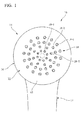
FIG. 1 is a view showing a shower head according to an exemplary embodiment of the invention. -
FIG. 2 is a view showing the internal structure of the shower head ofFIG. 1 . -
FIG. 3 is a further enlarged view of essential parts ofFIG. 2 . -
FIG. 4 is a perspective view showing constituent portions of the shower head ofFIG. 2 in a disassembled manner. -
FIG. 5 is a sectional view of the constituent portions of the shower head shown inFIG. 4 . -
FIG. 6 is a view showing an impeller unit ofFIG. 4 in a further disassembled manner. -
FIG. 7A is a view showing the impeller unit ofFIG. 4 in an assembled state. -
FIG. 7B is an enlarged view of part B ofFIG. 7A . -
FIG. 8 is a view showing a spiral flow generating member ofFIG. 4 from a different direction. -
FIG. 9A is a view showing the shape of an upper surface of an impeller inFIG. 6 . -
FIG. 9B is a view showing the shape of a lower surface of a bottom portion of the impeller inFIG. 6 . -
FIG. 10A is a schematic view showing a relationship between the impeller and the shower holes according to an exemplary embodiment of the invention. -
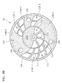
FIG. 10B is a view showing shower hole blocking portions and shower hole opening portions of the impeller according to an exemplary embodiment of the invention. -
FIG. 11 A is an A-A sectional view ofFIG. 2 . -
FIG. 11 B is a B-B sectional view ofFIG. 2 . -
FIG. 12A is a view showing essential parts according to another exemplary embodiment of the invention. -
FIG. 12B is a view showing essential parts according to still another exemplary embodiment of the invention. -
FIG. 13A is a schematic view showing related art. -
FIG. 13B is a schematic view showing related art. - An exemplary embodiment of the invention will be described in detail with reference to the drawings.
- In
FIG. 1 , a shower head (pulse shower device) 10 includes agrip part 12, ahead part 14, and awater dispersion plate 16 provided in thehead part 14. - A large number of shower holes 18 that penetrate from an inner surface to an outer surface (lower surface) are provided in the
water dispersion plate 16 so as to form four concentric circles. - Shower holes 18-1 at the outermost periphery of the concentric circles, shower holes 18-2 further inwards from the shower holes 18-1, shower holes 18-3 further inwards thereof, and shower holes 18-4 at the innermost periphery thereof are respectively shown in the drawing.
- The internal structure of the
head part 14 of theshower head 10 is specifically shown inFIG. 2 . - As shown in
FIG. 2 , thehead part 14 of theshower head 10 has anupper case 20, and acap 22 that is a lower case that closes an opening at a lower end (in the drawing) of theupper case 20. - The
upper case 20 has a cylindricalperipheral wall portion 24 that is provided with a female thread portion (not shown). - Meanwhile, the
cap 22 has a cylindrical risingportion 26 that is provided with a male thread portion (not shown). - The
cap 22 is screw-coupled to theupper case 20 by the male thread portion and the female thread portion. - The internal structure of the
head part 14 is shown in detail inFIGS. 2 to 5 . - As shown in
FIGS. 2 ,4 , and5 , anozzle seat 28, a ring-shapedpacking 30, animpeller unit 32, and a spiralflow generating member 34 are included inside thehead part 14. - The
impeller unit 32, as shown inFIGS. 2 and3 , has animpeller 36, and animpeller housing 38 that houses theimpeller 36 therein. - Additionally, the
impeller housing 38 is constituted of amain housing body 40 that serves as a nozzle seat retainer, and alid body 42. - In the present exemplary embodiment, other respective members excluding the
nozzle seat 28 and the packing 30, specifically, all of theupper case 20, thecap 22, theimpeller 36 of theimpeller unit 32, theimpeller housing 38, and the spiralflow generating member 34 are made of hard resin. - In the present exemplary embodiment, the
water dispersion plate 16 is configured to have a three-fold stacked structure of abottom portion 44 of thecap 22, aseat portion 46 of thenozzle seat 28 superposed on thebottom portion 44, and abottom portion 48 of themain housing body 40 further superposed on theseat portion 46. - Although the
nozzle seat 28 is made of rubber, the nozzle seal may be made of other elastomer materials. Thenozzle seat 28 has theseat portion 46, and a plurality ofnozzle portions 50 that protrude downward (downward direction in the drawing) from theseat portion 46. Therespective nozzle portions 50 are inserted through insertion holes 52 formed in thebottom portion 44 of thecap 22 made of resin, and respective tip portions thereof protrude downward. - The plurality of
nozzle portions 50 havenozzle holes 18A therein, respectively, and lower portions of the shower holes 18 are formed by the nozzle holes 18A. The diameter of thenozzle holes 18A is φ0.8 mm. - The
seat portion 46 of thenozzle seat 28, as shown inFIGS. 3 and4 , has a curved shape such that a lower surface thereof in the drawing become convex downward and an upper surface thereof in the drawing becomes concave downward, and therespective nozzle portions 50 having a shape that falls perpendicularly from the lower surface of theseat portion 46 are integrally formed in theseat portion 46. - In correspondence with the above shape, a lower surface of the
main housing body 40 that serves as the above nozzle retainer forms a convex surface corresponding to the concave surface of theseat portion 46 of thenozzle seat 28. - A large number of
communication holes 18B that communicates with the nozzle holes 18A and form upper portions of the shower holes 18 are provided in thebottom portion 48 of themain housing body 40 so as to pass through thebottom portion 48. - In
FIG. 2 , acylindrical portion 54 is provided at a central portion of theupper case 20, and a waterchannel forming member 56 that has a bottomed cylindrical shape and is made of resin is assembled into thecylindrical portion 54. - Additionally, a
cylindrical portion 58 that rises upward at a central portion of the spiralflow generating member 34 is inserted into thecylindrical portion 54. Aninflow chamber 62 into which the water from thewater channel 60 is made to flow is formed inside thecylindrical portion 54 by the waterchannel forming member 56 and thecylindrical portion 58. - The spiral
flow generating member 34 inclines gently downward in an outer circumferential direction from the center thereof, and has anupper wall portion 64 that has a flat shape which widens in a direction perpendicular to an axis (axis-perpendicular direction) thereof, and a cylindricalperipheral wall portion 66 that falls downward at an outer peripheral end of theupper wall portion 64. Awater chamber 68 configured to generate a spiral flow is formed between theupper wall portion 64 and thelid body 42 of theimpeller housing 38. - The spiral
flow generating member 34 is provided withstationary vanes 70 that fall from theupper wall portion 64 and extend in a partial spiral shape from an inner peripheral end toward an outer peripheral end, and thestationary vanes 70 abut against an upper surface of thelid body 42 of theimpeller housing 38. - The spiral
flow generating member 34 changes the flow of the water, which has flowed into theinflow chamber 62 from thewater channel 60 and has further flowed in an axial direction in a downward direction (in the drawing) of theinflow chamber 62, in the axis-perpendicular direction, and makes the water flow to an outer peripheral side. - In that case, the flow of the water that flows in the axis-perpendicular direction toward the outer peripheral side due to the flow straightening and the guidance action of the
stationary vanes 70 that have the partial spiral shape is used as the spiral flow, and the spiral flow is made to abut against the cylindricalperipheral wall portion 66. - Thereafter, the flow of the water that has abutted to the
peripheral wall portion 66 is reversed in direction, and becomes an inward flow in the axis-perpendicular direction, and the water flows into theimpeller housing 38 of theimpeller unit 32 vigorously. - The
impeller unit 32 forms awater chamber 72 inside theimpeller housing 38, and theimpeller 36 is rotatably housed in thewater chamber 72. - The
impeller housing 38 is divided into themain housing body 40 and thelid body 42 as described above, and themain housing body 40 is configured to serve also as the nozzle retainer. - The
main housing body 40 is a member that has a cylindricalperipheral wall portion 74 and abottom portion 48 and opens at an upper end thereof, and the opening portion of the upper end thereof is closed by thelid body 42. - A fixing
hole 76 passing through thebottom portion 48 is provided at a central portion of thebottom portion 48 of themain housing body 40. - The
lid body 42 is provided with ashaft portion 78 that falls from a central portion thereof. Anelastic claw 80 is further provided at a lower portion of theshaft portion 78, and theelastic claw 80 is inserted into the fixinghole 76 of themain housing body 40 and is elastically latched to the fixinghole 76. Thelid body 42 and themain housing body 40 are assembled together by latching of theelastic claw 80 to the fixinghole 76. - As shown in
FIGS. 6 ,7A, and 7B , an innerfitting portion 82, which protrudes upward (in the drawing) in a stepped shape with respect to an outer peripheral portion and forms an annular shape in a circumferential direction, is provided at an upper end portion and an inner peripheral portion of theperipheral wall portion 74 of themain housing body 40. - An outer peripheral portion of the
lid body 42 is provided withbend portions 84 that have a downward bent shape (in the drawing). - Outer peripheral portions of the
bend portions 84 are annular outerfitting portions 86, and the outerfitting portions 86 are fitted to the innerfitting portion 82 of themain housing body 40 in an external fitting state. - A larger number of
spray ports 88 are provided at regular intervals in the circumferential direction in thebend portions 84 of thelid body 42, and allow a water stream, which has abutted against theperipheral wall portion 66 of the spiralflow generating member 34 and of which the direction has been reversed inward, to pass therethrough toward thewater chamber 72 within theimpeller housing 38. - The water stream that has passed through the
spray ports 88 becomes a sprayed water stream and rotationally drives theimpeller 36 within thewater chamber 72, specifically, hitsvanes 102 vigorously and rotationally drives theimpeller 36. - The
spray ports 88 open in outer surfaces of thebend portions 84. Anopening 90 is shown inFIG. 7B . - The
spray ports 88, as shown inFIG. 11 B , are inclined with respect to the circumferential direction of thebend portions 84 of thelid body 42 and theperipheral wall portion 74 of themain housing body 40. - The inclination direction of the
spray ports 88 is determined such that the water stream, which has hit theperipheral wall portion 66 of the spiralflow generating member 34 while generating a spiral stream and of which the direction has been reversed inward, is sprayed to theimpeller 36 within thewater chamber 72 while the spiral flow is maintained. - As is clear from the above descriptions, in the present exemplary embodiment, the
impeller housing 38, specifically, thelid body 42 is constituted as a water stream spraying member that passes the water from an upstream portion therethrough, causes the passed water to collide against theimpeller 36 as the sprayed water stream, and rotationally drives theimpeller 36. - In addition, as shown in
FIG. 6 , positioningconvex portions 92 are provided in two places, which are separated by 180° in the circumferential direction, on thelid body 42. - Positioning
concave portions 94 are provided at positions corresponding to the positioningconvex portions 92 in theperipheral wall portion 74 of themain housing body 40. - The
lid body 42 and themain housing body 40 are positioned in the circumferential direction by the concavo-convex fitting between the positioningconvex portions 92 and the positioningconcave portions 94. - As shown in
FIG. 8 , positioningconcave portions 96 are similarly provided also in the spiralflow generating member 34. Thelid body 42 and the spiralflow generating member 34 are positioned in the circumferential direction on the basis of the concavo-convex fitting of the positioningconvex portions 92 of thelid body 42 into the positioningconcave portions 96. That is, theimpeller housing 38 is positioned in the circumferential direction with respect to the spiralflow generating member 34. - In addition, in the present exemplary embodiment, if the
cap 22 is screwed into theupper case 20 upward inFIG. 2 , the spiralflow generating member 34 is pushed upward (in the drawing) via the ring-shapedpacking 30. Then, the spiral flow generating member is fixed and assembled so as to abut against thecylindrical portion 54 of theupper case 20. - In this case, the
impeller housing 38 of theimpeller unit 32 hits the stationarystationary vanes 70 of the spiralflow generating member 34, and is sandwiched together with thebottom portion 44 of thecap 22, whereby theimpeller housing 38 is fixed. - In this case, a downward force is applied from the
main housing body 40, which also serves as the nozzle retainer, to thenozzle seat 28 by a sandwiching force, and thenozzle seat 28 is pressed against thebottom portion 44 of thecap 22 downward. - In addition, in
FIG. 4 , the ring-shapedpacking 30 is provided with anannular seat 98 consisting of a mesh member made of resin. In an assembled state, theannular seat 98 is superposed on an inner surface of thewater dispersion plate 16, specifically, on an inner surface of theseat portion 46 of thenozzle seat 28, at a position where the annular seat covers the shower holes 18-1 at the outermost periphery. - The specific shapes of the
impeller 36 are shown inFIGS. 9A to 11 B . - As shown in the drawings, the
impeller 36 has a cylindricalfitting portion 100 at a central portion thereof, and thefitting portion 100 is fitted to theshaft portion 78 of the central portion of thelid body 42 of the impeller housing 38 (refer toFIGS. 2 and3 ). - The
impeller 36 is rotationally driven around theshaft portion 78 on the basis of the fitting between theshaft portion 78 and thefitting portion 100. - In addition, since the
fitting portion 100 protrudes slightly further downward (inFIG. 3 ) than other portions, the fitting portion abuts against an inner surface of themain housing body 40 in the protruding portion, and supports theentire impeller 36 together withballs 108 to be described below during rotation. - As shown in
FIGS. 9A to 11 B , theimpeller 36 has a large number of thevanes 102, which extend in a partial spiral shape from the center in the outer circumferential direction, at regular intervals in the circumferential direction. Thevanes 102, as shown inFIGS. 11 A and 11 B , are provided so as to form a partial spiral shape in a direction opposite to that of thestationary vanes 70 of the spiralflow generating member 34 in a plan view. - Additionally, the
impeller 36 hasball holding portions 104 in three places shifted by 120° from each other in the circumferential direction. - The
ball holding portions 104, as shown inFIGS. 3 and9B , have holdingholes 106, respectively, and hold thehard balls 108 made of resin in the holding holes 106. - Lower portions of the
balls 108 protrude slightly downward inFIG. 3 from the holdingholes 106, and theballs 108 rollably abut against an inner surface of thebottom portion 48 of themain housing body 40 of theimpeller housing 38 in the protruding portions. - Inner surfaces of the holding
holes 106 have a substantially partial spherical shape. However, the sizes of openings of the inner surfaces and lower ends (in the drawing) of the holding holes are slightly greater than those of theballs 108. - The
vanes 102 are coupled together by a rib-shapedcoupling portion 109 at the outermost periphery, a rib-shapedcoupling portion 111 located closer to the inner peripheral side than thecoupling portion 109, a rib-shapedcoupling portion 113 located still closer to the inner peripheral side than thecoupling portion 109, and showerhole blocking portions 110 to be described below. - All of the
coupling portions - A downstream portion of the
impeller 36 is provided with the showerhole blocking portions 110 that extend in a predetermined circumference along the inner surface of thebottom portion 48 of themain housing body 40 and partially close a lower surface (in the drawing) of theimpeller 36. The showerhole blocking portions 110 cover and block the communication holes 18B of thebottom portion 48, that is, the shower holes 18. - Additionally, the portions of the
impeller 36 excluding the showerhole blocking portions 110 are provided with showerhole opening portions 112 that open (however, thevanes 102 and thecoupling portions bottom portion 48 of themain housing body 40. - The
vanes 102 located in the showerhole blocking portions 110 are provided on upper surfaces (in the drawing) of the showerhole blocking portions 110. - Some of the
vanes 102 provided on the showerhole opening portions 112 are connected to the cylindricalfitting portion 100 of the central portion byarms 114 because portions thereof on a root side are formed as thearms 114. - In the present exemplary embodiment, a shower hole blocking portion at an inner peripheral portion with respect to the
coupling portion 113 is only one showerhole blocking portion 110A. Meanwhile, an outer peripheral portion is further provided with three shower hole blocking portions of showerhole blocking portions 110B-1, 110B-2, and 110B-3. - Similarly, although the shower hole opening portion at the inner peripheral portion is only one shower
hole opening portion 112A, the outer peripheral portion is provided with the three shower hole opening portions of the showerhole opening portion 112B-1, 112B-2, and 112B-3. - In addition, the shower
hole blocking portion 110A is provided over a semicircle (refer toFIG. 10A ), and the ratio of a circumferential length LA (refer toFIG. 10B ) to the whole circumferential length (circumferential length in the same circumference) is 0.5 with the whole circumferential length being 1. - The same applies to the shower
hole opening portion 112A, and the ratio of a circumferential length MA of the showerhole opening portion 112A to the whole circumferential length is 0.5. - Meanwhile, the ratio of a circumferential length LB-1 of the shower
hole blocking portion 110B-1 of the outer peripheral portion to the whole circumferential length is 0.21, and the ratio of a circumferential length LB-2 of the showerhole blocking portion 110B-2 to the whole circumferential length is 0.28. The ratio of a length obtained by summing the lengths LB-1 and LB-2 to the whole circumferential length is about 0.5, and is almost the same as the ratio of the circumferential length LA of the showerhole blocking portion 110A at the inner peripheral portion to the whole circumferential length. - That is, the shower hole blocking portions equivalent to half a circumference are configured so as to be distributed as the shower
hole blocking portions 110B-1 and 110B-2 at the outer peripheral portion. - In addition, another shower
hole blocking portion 110B-3 at the outer peripheral portion is provided mainly for theball holding portion 104. The ratio of a circumferential length LB-3 of the showerhole blocking portion 110B-3 to the whole circumferential length is 0.08. - In addition, the ratio of a circumferential length MB-1 of the shower
hole opening portion 112B-1 to the whole circumferential length is 0.25, the ratio of a circumferential length MB-3 of the showerhole opening portion 112B-3 to the whole circumferential length is 0.12, and the ratio of a circumferential length MB-2 of the showerhole opening portion 112B-2 to the whole circumferential length is 0.05. - Next, the operation of the pulse shower device of the present exemplary embodiment will be described.
- In the pulse shower device of the present exemplary embodiment, the water, which has flowed into the
inflow chamber 62 from thewater channel 60 ofFIG. 2 , flows through theinflow chamber 62 in the axial direction in the downward direction inFIG. 2 , and the direction of flow thereof is changed to an outward direction in the axis-perpendicular direction by the spiralflow generating member 34. - That is, the water stream in the axial direction of the central portion serves as a flow in an outward direction in the axis-perpendicular direction within the
water chamber 68 of the spiralflow generating member 34. In that case, the outward flow serves as the spiral flow due to an action caused by thestationary vanes 70 of the spiralflow generating member 34. - The outward spiral flow hits the
peripheral wall portion 66 of the spiralflow generating member 34 and next flows to an inward direction in the axis-perpendicular direction, and is then sprayed through thespray ports 88 of theimpeller housing 38 that serves as the water stream spraying member from the lateral side on the outer peripheral side of theimpeller 36 to theimpeller 36. - The sprayed water stream hits the concave surfaces of the
partial spiral vanes 102 of theimpeller 36 and rotates theimpeller 36 while maintaining the spiral flow in the direction P ofFIGS. 11 A and 11 B . - In detail, the
impeller 36 is rotationally driven around theshaft portion 78 of thelid body 42 of theimpeller housing 38. Theimpeller 36 is smoothly rotated around theshaft portion 78 by the bearing action obtained by theballs 108 provided in three places in the circumferential direction. - The shower
hole blocking portions 110 and the showerhole opening portions 112 are rotated around theshaft portion 78 by the above rotational motion. Accordingly, the shower holes 18 are blocked and opened, and water is intermittently discharged in pulses. - As described above, in the present exemplary embodiment, the number of the shower
hole blocking portions 110 and the showerhole opening portions 112 that are located on the same circumference is greater at the outer peripheral portion than at the inner peripheral portion, and the time interval from the blocking of the shower holes 18 at the outer peripheral portion to the opening thereof and from the opening thereof to the closing thereof is made shorter than the time interval at the inner peripheral portion. Accordingly, a pulsating sensation of water is relaxed even in a case where the pulse shower device is enlarged, and a sensation while showering in water is prevented from deteriorating due to an excessively strong pulsating sensation of the water. Therefore, a user can be made to feel a comfortable sensation while showering in water. -
FIGS. 12A and12B show other exemplary embodiments of the invention. -
FIG. 12A shows an example in which the showerhole blocking portions 110 are provided withslit holes 116 passing through the showerhole blocking portions 110 in a thickness direction. - Forces that push the shower
hole blocking portions 110 downward in thewater chamber 72 are applied to the showerhole blocking portions 110. Smooth rotation of theimpeller 36 tends to be impaired due to downward forces that are partially applied in the circumferential direction. - Thus, in the present example, the rotation of the
impeller 36 is made smooth by providing the penetrating slit holes 116 in the showerhole blocking portions 110 and relieving pressure with the slit holes 116. - Usually, since the slit holes 116 are extremely fine holes in which the ratio of the circumferential length thereof to the whole circumferential length is less than 0.04, the slit holes 116 do not substantially serve as the shower hole opening portions. The ratio of the circumferential length of the shower
hole blocking portions 110 and the showerhole opening portions 112 arranged on the same circumference to the whole circumferential length is equal to or higher than 0.04. - In the example described above, the
impeller 36 is partitioned into two of the inner peripheral portion and the outer peripheral portion, and the number of the shower hole blocking portions and the shower opening portions is made greater at the outer peripheral portion than at the inner peripheral portion. On the other hand, as shown inFIG. 12B , it is also possible to use a configuration in which theimpeller 36 is partitioned into the inner peripheral portion, the outer peripheral portion, and an intermediate portion between the inner and outer peripheral portions, the number of showerhole blocking portions 110C at the intermediate portion is made greater than at the inner peripheral portion, and the number of showerhole blocking portions 110B at the outer peripheral portion is made still greater. - In addition, the same applies to the shower
hole opening portions 112, and it is also possible to use a configuration in which the number of the showerhole opening portions 112C at the intermediate portion is made greater than the number of the showerhole opening portions 112A at the innermost periphery, and the number of the showerhole opening portions 112B at the outermost periphery is made still greater. - Although the exemplary embodiment of the invention has been described in detail above, the configuration of the invention can be variously changed without departing from the scope thereof such that the shower hole blocking portions and the shower hole opening portions can be provided with numbers different from those above.
-
- 16: water dispersion plate
- 18, 18-1, 18-2, 18-3, 18-4: shower hole
- 36: impeller
- 110, 110A, 110B-1, 110B-2, 110B-3, 110C: shower hole blocking portion
- 112, 112A, 112B-1, 112B-2, 112B-3, 112C: shower hole opening portion
Claims (1)
- A pulse shower device comprising:a water dispersion plate that comprises an inner surface and an outer surface, and a plurality of shower holes that penetrate from the inner surface to the outer surface; andan impeller that comprises: a shower hole blocking portion that is formed over a predetermined circumferential length along the inner surface in a downstream portion of the inner surface of the water dispersion plate, and covers the plurality of shower holes; a shower hole opening portion that opens toward the inner surface; a plurality of vanes; an inner peripheral portion; and an outer peripheral portion, that is provided on an upstream portion of the inner surface of the water dispersion plate, and that rotates around an axis due to a water stream hitting the vanes,wherein the shower hole blocking portion and the shower hole opening portion are alternately arranged in a circumferential direction on the same circumference, and rotate around the axis through the rotation of the impeller to intermittently block and open the shower holes, and intermittently discharge water in pulses from the shower holes,wherein the number of shower hole blocking portions and shower hole opening portions that are arranged on the same circumference at the outer peripheral portion is greater than the number of shower hole blocking portions and shower hole opening portions at the inner peripheral portion, andwherein a time interval from the blocking of the shower holes at the outer peripheral portion to the closing thereof and from the opening thereof to the blocking thereof is shorter than a time interval from the blocking of the shower holes at the inner peripheral portion to the closing thereof and from the opening thereof to the blocking thereof.
Applications Claiming Priority (2)
| Application Number | Priority Date | Filing Date | Title |
|---|---|---|---|
| JP2013011553A JP5879635B2 (en) | 2013-01-24 | 2013-01-24 | Pulse shower device |
| PCT/JP2014/050819 WO2014115656A1 (en) | 2013-01-24 | 2014-01-17 | Pulse shower device |
Publications (3)
| Publication Number | Publication Date |
|---|---|
| EP2949249A1 true EP2949249A1 (en) | 2015-12-02 |
| EP2949249A4 EP2949249A4 (en) | 2016-01-27 |
| EP2949249B1 EP2949249B1 (en) | 2019-07-24 |
Family
ID=51227448
Family Applications (1)
| Application Number | Title | Priority Date | Filing Date |
|---|---|---|---|
| EP14743143.1A Active EP2949249B1 (en) | 2013-01-24 | 2014-01-17 | Pulse shower device |
Country Status (5)
| Country | Link |
|---|---|
| US (1) | US9821326B2 (en) |
| EP (1) | EP2949249B1 (en) |
| JP (1) | JP5879635B2 (en) |
| CN (1) | CN104936496B (en) |
| WO (1) | WO2014115656A1 (en) |
Cited By (2)
| Publication number | Priority date | Publication date | Assignee | Title |
|---|---|---|---|---|
| GB2536784A (en) * | 2015-02-07 | 2016-09-28 | Kylin Sanitary Tech (Xiamen) Co Ltd | A water outlet structure for generating candle flame shaped water and a shower head mounting the same |
| IT201700029743A1 (en) * | 2017-03-17 | 2018-09-17 | Carovani E Parigi Di Parigi Davide | Shower. |
Families Citing this family (14)
| Publication number | Priority date | Publication date | Assignee | Title |
|---|---|---|---|---|
| JP5660346B1 (en) * | 2013-09-11 | 2015-01-28 | Toto株式会社 | shower head |
| RS55899B1 (en) * | 2014-10-13 | 2017-08-31 | Ftt Doo | SHOWER HANDLE WITH TORUS REGULATOR AND MAGNETIC RING |
| CN205056287U (en) * | 2015-09-26 | 2016-03-02 | 厦门建霖工业有限公司 | Rotatory splash of face lid spills |
| JP6268135B2 (en) * | 2015-09-28 | 2018-01-24 | 株式会社タカギ | Micro bubble shower device |
| CN105312168B (en) * | 2015-11-03 | 2017-10-24 | 重庆金鑫智慧科技有限公司 | Pulsating water-saving apparatus for shower bath with endoporus |
| JP2018051488A (en) * | 2016-09-29 | 2018-04-05 | 株式会社Lixil | Water discharge parts |
| AU2016426210A1 (en) * | 2016-10-12 | 2019-03-21 | Energy Harvest As | Rotary valve device and liquid lifting device comprising the same |
| CN206382134U (en) * | 2017-01-05 | 2017-08-08 | 温州万康宠物用品有限公司 | A kind of shower head structure |
| KR101960157B1 (en) * | 2017-03-20 | 2019-07-15 | 영 근 송 | Air bubble type shower |
| KR101927314B1 (en) * | 2017-05-23 | 2018-12-10 | 이해창 | Pulsation generator apparatus of fluid |
| WO2018216896A1 (en) * | 2017-05-23 | 2018-11-29 | 이해창 | Fluid pulsation generation apparatus |
| JP6448716B1 (en) * | 2017-07-04 | 2019-01-09 | Sanei株式会社 | Structure of water discharge part and shower device |
| CN206897677U (en) * | 2017-07-10 | 2018-01-19 | 恺霖卫浴科技(厦门)有限公司 | A kind of adjustable gondola water faucet of flow |
| KR102679752B1 (en) * | 2022-08-10 | 2024-07-01 | 이해창 | Pulsation generating apparatus of fluid with open and close control apparatus |
Family Cites Families (14)
| Publication number | Priority date | Publication date | Assignee | Title |
|---|---|---|---|---|
| NO144193C (en) * | 1976-02-18 | 1981-07-15 | Grohe Kg Hans | MASSAGE SHOWER HEAD. |
| US4131233A (en) * | 1976-08-11 | 1978-12-26 | Shulamith Koenig | Selectively-controlled pulsating water shower head |
| US4398668A (en) * | 1979-05-21 | 1983-08-16 | Emile Jette | Showerhead control |
| US4254914A (en) * | 1979-09-14 | 1981-03-10 | Shames Sidney J | Pulsating shower head |
| US4412834A (en) * | 1981-06-05 | 1983-11-01 | Baxter Travenol Laboratories | Antimicrobial ultraviolet irradiation of connector for continuous ambulatory peritoneal dialysis |
| CA1173083A (en) * | 1981-12-10 | 1984-08-21 | Sigurdur G. Petursson | Shower pulsator |
| DE3245756A1 (en) * | 1982-12-10 | 1984-06-14 | Hans Grohe Gmbh & Co Kg, 7622 Schiltach | Massage shower |
| US4629125A (en) * | 1984-08-27 | 1986-12-16 | Fuyi Liu | Spray nozzle |
| US4801091A (en) * | 1988-03-31 | 1989-01-31 | Sandvik Arne P | Pulsating hot and cold shower head |
| JPH01297162A (en) * | 1988-05-25 | 1989-11-30 | Noritz Corp | Multifunctional shower head |
| JP2649452B2 (en) | 1991-10-30 | 1997-09-03 | 株式会社イナックス | Massage shower head |
| US8794543B2 (en) | 2006-12-28 | 2014-08-05 | Water Pik, Inc. | Low-speed pulsating showerhead |
| DE102008015969A1 (en) | 2008-03-20 | 2009-09-24 | Hansgrohe Ag | shower head |
| JP5891527B2 (en) * | 2010-12-07 | 2016-03-23 | 株式会社Lixil | Shower water discharge device |
-
2013
- 2013-01-24 JP JP2013011553A patent/JP5879635B2/en not_active Expired - Fee Related
-
2014
- 2014-01-17 CN CN201480005623.6A patent/CN104936496B/en not_active Expired - Fee Related
- 2014-01-17 WO PCT/JP2014/050819 patent/WO2014115656A1/en not_active Ceased
- 2014-01-17 EP EP14743143.1A patent/EP2949249B1/en active Active
- 2014-01-17 US US14/762,624 patent/US9821326B2/en not_active Expired - Fee Related
Cited By (2)
| Publication number | Priority date | Publication date | Assignee | Title |
|---|---|---|---|---|
| GB2536784A (en) * | 2015-02-07 | 2016-09-28 | Kylin Sanitary Tech (Xiamen) Co Ltd | A water outlet structure for generating candle flame shaped water and a shower head mounting the same |
| IT201700029743A1 (en) * | 2017-03-17 | 2018-09-17 | Carovani E Parigi Di Parigi Davide | Shower. |
Also Published As
| Publication number | Publication date |
|---|---|
| EP2949249B1 (en) | 2019-07-24 |
| CN104936496A (en) | 2015-09-23 |
| CN104936496B (en) | 2018-04-10 |
| JP5879635B2 (en) | 2016-03-08 |
| US20150367355A1 (en) | 2015-12-24 |
| WO2014115656A1 (en) | 2014-07-31 |
| JP2014140547A (en) | 2014-08-07 |
| EP2949249A4 (en) | 2016-01-27 |
| US9821326B2 (en) | 2017-11-21 |
Similar Documents
| Publication | Publication Date | Title |
|---|---|---|
| EP2949249B1 (en) | Pulse shower device | |
| JP5891527B2 (en) | Shower water discharge device | |
| US10994289B2 (en) | Showerhead with turbine driven shutter | |
| US5862985A (en) | Showerhead | |
| CN103930215B (en) | A kind of shower nozzle | |
| JP5891528B2 (en) | Shower water discharge device | |
| EP2191756B1 (en) | Shower device | |
| GB2561652A (en) | Centrifugal water spray structure and showerhead including the same | |
| JP6448716B1 (en) | Structure of water discharge part and shower device | |
| CN101516521B (en) | Pulsating hydromassage components for showers and hand showers | |
| JP6067388B2 (en) | Pulse shower device | |
| PL196434B1 (en) | Shower head | |
| JP2013162985A (en) | Shower water discharging device | |
| WO2011039647A2 (en) | Shower head | |
| JP2007260563A (en) | Washing equipment and shower head | |
| JP2009106732A (en) | Water discharge device | |
| JP2014140549A (en) | Pulse shower device | |
| JP2010069445A (en) | Spout device | |
| GB2388332A (en) | Dual function showerhead for steam and water | |
| JP2004283811A (en) | Discharge nozzle | |
| CN211816729U (en) | Shower nozzle, water jet equipment and electronic toilet of using this shower nozzle | |
| JP6341463B2 (en) | Water discharge device | |
| KR20180128323A (en) | Pulsation generator apparatus of fluid | |
| JP2007130332A (en) | Jet injection device | |
| KR200336391Y1 (en) | Shower nozzle |
Legal Events
| Date | Code | Title | Description |
|---|---|---|---|
| PUAI | Public reference made under article 153(3) epc to a published international application that has entered the european phase |
Free format text: ORIGINAL CODE: 0009012 |
|
| 17P | Request for examination filed |
Effective date: 20150717 |
|
| AK | Designated contracting states |
Kind code of ref document: A1 Designated state(s): AL AT BE BG CH CY CZ DE DK EE ES FI FR GB GR HR HU IE IS IT LI LT LU LV MC MK MT NL NO PL PT RO RS SE SI SK SM TR |
|
| AX | Request for extension of the european patent |
Extension state: BA ME |
|
| A4 | Supplementary search report drawn up and despatched |
Effective date: 20160107 |
|
| RIC1 | Information provided on ipc code assigned before grant |
Ipc: B05B 1/08 20060101ALI20151222BHEP Ipc: B05B 1/18 20060101ALI20151222BHEP Ipc: B05B 3/04 20060101ALI20151222BHEP Ipc: A47K 3/28 20060101AFI20151222BHEP |
|
| DAX | Request for extension of the european patent (deleted) | ||
| GRAP | Despatch of communication of intention to grant a patent |
Free format text: ORIGINAL CODE: EPIDOSNIGR1 |
|
| STAA | Information on the status of an ep patent application or granted ep patent |
Free format text: STATUS: GRANT OF PATENT IS INTENDED |
|
| INTG | Intention to grant announced |
Effective date: 20190221 |
|
| GRAS | Grant fee paid |
Free format text: ORIGINAL CODE: EPIDOSNIGR3 |
|
| GRAA | (expected) grant |
Free format text: ORIGINAL CODE: 0009210 |
|
| STAA | Information on the status of an ep patent application or granted ep patent |
Free format text: STATUS: THE PATENT HAS BEEN GRANTED |
|
| AK | Designated contracting states |
Kind code of ref document: B1 Designated state(s): AL AT BE BG CH CY CZ DE DK EE ES FI FR GB GR HR HU IE IS IT LI LT LU LV MC MK MT NL NO PL PT RO RS SE SI SK SM TR |
|
| REG | Reference to a national code |
Ref country code: GB Ref legal event code: FG4D |
|
| REG | Reference to a national code |
Ref country code: CH Ref legal event code: EP |
|
| REG | Reference to a national code |
Ref country code: DE Ref legal event code: R096 Ref document number: 602014050479 Country of ref document: DE |
|
| REG | Reference to a national code |
Ref country code: AT Ref legal event code: REF Ref document number: 1157159 Country of ref document: AT Kind code of ref document: T Effective date: 20190815 |
|
| REG | Reference to a national code |
Ref country code: IE Ref legal event code: FG4D |
|
| REG | Reference to a national code |
Ref country code: NL Ref legal event code: MP Effective date: 20190724 |
|
| REG | Reference to a national code |
Ref country code: LT Ref legal event code: MG4D |
|
| REG | Reference to a national code |
Ref country code: AT Ref legal event code: MK05 Ref document number: 1157159 Country of ref document: AT Kind code of ref document: T Effective date: 20190724 |
|
| PG25 | Lapsed in a contracting state [announced via postgrant information from national office to epo] |
Ref country code: FI Free format text: LAPSE BECAUSE OF FAILURE TO SUBMIT A TRANSLATION OF THE DESCRIPTION OR TO PAY THE FEE WITHIN THE PRESCRIBED TIME-LIMIT Effective date: 20190724 Ref country code: NO Free format text: LAPSE BECAUSE OF FAILURE TO SUBMIT A TRANSLATION OF THE DESCRIPTION OR TO PAY THE FEE WITHIN THE PRESCRIBED TIME-LIMIT Effective date: 20191024 Ref country code: SE Free format text: LAPSE BECAUSE OF FAILURE TO SUBMIT A TRANSLATION OF THE DESCRIPTION OR TO PAY THE FEE WITHIN THE PRESCRIBED TIME-LIMIT Effective date: 20190724 Ref country code: BG Free format text: LAPSE BECAUSE OF FAILURE TO SUBMIT A TRANSLATION OF THE DESCRIPTION OR TO PAY THE FEE WITHIN THE PRESCRIBED TIME-LIMIT Effective date: 20191024 Ref country code: AT Free format text: LAPSE BECAUSE OF FAILURE TO SUBMIT A TRANSLATION OF THE DESCRIPTION OR TO PAY THE FEE WITHIN THE PRESCRIBED TIME-LIMIT Effective date: 20190724 Ref country code: NL Free format text: LAPSE BECAUSE OF FAILURE TO SUBMIT A TRANSLATION OF THE DESCRIPTION OR TO PAY THE FEE WITHIN THE PRESCRIBED TIME-LIMIT Effective date: 20190724 Ref country code: PT Free format text: LAPSE BECAUSE OF FAILURE TO SUBMIT A TRANSLATION OF THE DESCRIPTION OR TO PAY THE FEE WITHIN THE PRESCRIBED TIME-LIMIT Effective date: 20191125 Ref country code: HR Free format text: LAPSE BECAUSE OF FAILURE TO SUBMIT A TRANSLATION OF THE DESCRIPTION OR TO PAY THE FEE WITHIN THE PRESCRIBED TIME-LIMIT Effective date: 20190724 Ref country code: LT Free format text: LAPSE BECAUSE OF FAILURE TO SUBMIT A TRANSLATION OF THE DESCRIPTION OR TO PAY THE FEE WITHIN THE PRESCRIBED TIME-LIMIT Effective date: 20190724 |
|
| PG25 | Lapsed in a contracting state [announced via postgrant information from national office to epo] |
Ref country code: AL Free format text: LAPSE BECAUSE OF FAILURE TO SUBMIT A TRANSLATION OF THE DESCRIPTION OR TO PAY THE FEE WITHIN THE PRESCRIBED TIME-LIMIT Effective date: 20190724 Ref country code: LV Free format text: LAPSE BECAUSE OF FAILURE TO SUBMIT A TRANSLATION OF THE DESCRIPTION OR TO PAY THE FEE WITHIN THE PRESCRIBED TIME-LIMIT Effective date: 20190724 Ref country code: GR Free format text: LAPSE BECAUSE OF FAILURE TO SUBMIT A TRANSLATION OF THE DESCRIPTION OR TO PAY THE FEE WITHIN THE PRESCRIBED TIME-LIMIT Effective date: 20191025 Ref country code: ES Free format text: LAPSE BECAUSE OF FAILURE TO SUBMIT A TRANSLATION OF THE DESCRIPTION OR TO PAY THE FEE WITHIN THE PRESCRIBED TIME-LIMIT Effective date: 20190724 Ref country code: RS Free format text: LAPSE BECAUSE OF FAILURE TO SUBMIT A TRANSLATION OF THE DESCRIPTION OR TO PAY THE FEE WITHIN THE PRESCRIBED TIME-LIMIT Effective date: 20190724 Ref country code: IS Free format text: LAPSE BECAUSE OF FAILURE TO SUBMIT A TRANSLATION OF THE DESCRIPTION OR TO PAY THE FEE WITHIN THE PRESCRIBED TIME-LIMIT Effective date: 20191124 |
|
| PG25 | Lapsed in a contracting state [announced via postgrant information from national office to epo] |
Ref country code: TR Free format text: LAPSE BECAUSE OF FAILURE TO SUBMIT A TRANSLATION OF THE DESCRIPTION OR TO PAY THE FEE WITHIN THE PRESCRIBED TIME-LIMIT Effective date: 20190724 |
|
| PG25 | Lapsed in a contracting state [announced via postgrant information from national office to epo] |
Ref country code: RO Free format text: LAPSE BECAUSE OF FAILURE TO SUBMIT A TRANSLATION OF THE DESCRIPTION OR TO PAY THE FEE WITHIN THE PRESCRIBED TIME-LIMIT Effective date: 20190724 Ref country code: PL Free format text: LAPSE BECAUSE OF FAILURE TO SUBMIT A TRANSLATION OF THE DESCRIPTION OR TO PAY THE FEE WITHIN THE PRESCRIBED TIME-LIMIT Effective date: 20190724 Ref country code: DK Free format text: LAPSE BECAUSE OF FAILURE TO SUBMIT A TRANSLATION OF THE DESCRIPTION OR TO PAY THE FEE WITHIN THE PRESCRIBED TIME-LIMIT Effective date: 20190724 Ref country code: IT Free format text: LAPSE BECAUSE OF FAILURE TO SUBMIT A TRANSLATION OF THE DESCRIPTION OR TO PAY THE FEE WITHIN THE PRESCRIBED TIME-LIMIT Effective date: 20190724 Ref country code: EE Free format text: LAPSE BECAUSE OF FAILURE TO SUBMIT A TRANSLATION OF THE DESCRIPTION OR TO PAY THE FEE WITHIN THE PRESCRIBED TIME-LIMIT Effective date: 20190724 |
|
| PG25 | Lapsed in a contracting state [announced via postgrant information from national office to epo] |
Ref country code: SM Free format text: LAPSE BECAUSE OF FAILURE TO SUBMIT A TRANSLATION OF THE DESCRIPTION OR TO PAY THE FEE WITHIN THE PRESCRIBED TIME-LIMIT Effective date: 20190724 Ref country code: CZ Free format text: LAPSE BECAUSE OF FAILURE TO SUBMIT A TRANSLATION OF THE DESCRIPTION OR TO PAY THE FEE WITHIN THE PRESCRIBED TIME-LIMIT Effective date: 20190724 Ref country code: IS Free format text: LAPSE BECAUSE OF FAILURE TO SUBMIT A TRANSLATION OF THE DESCRIPTION OR TO PAY THE FEE WITHIN THE PRESCRIBED TIME-LIMIT Effective date: 20200224 Ref country code: SK Free format text: LAPSE BECAUSE OF FAILURE TO SUBMIT A TRANSLATION OF THE DESCRIPTION OR TO PAY THE FEE WITHIN THE PRESCRIBED TIME-LIMIT Effective date: 20190724 |
|
| REG | Reference to a national code |
Ref country code: DE Ref legal event code: R097 Ref document number: 602014050479 Country of ref document: DE |
|
| PLBE | No opposition filed within time limit |
Free format text: ORIGINAL CODE: 0009261 |
|
| STAA | Information on the status of an ep patent application or granted ep patent |
Free format text: STATUS: NO OPPOSITION FILED WITHIN TIME LIMIT |
|
| PG2D | Information on lapse in contracting state deleted |
Ref country code: IS |
|
| 26N | No opposition filed |
Effective date: 20200603 |
|
| PG25 | Lapsed in a contracting state [announced via postgrant information from national office to epo] |
Ref country code: MC Free format text: LAPSE BECAUSE OF FAILURE TO SUBMIT A TRANSLATION OF THE DESCRIPTION OR TO PAY THE FEE WITHIN THE PRESCRIBED TIME-LIMIT Effective date: 20190724 Ref country code: SI Free format text: LAPSE BECAUSE OF FAILURE TO SUBMIT A TRANSLATION OF THE DESCRIPTION OR TO PAY THE FEE WITHIN THE PRESCRIBED TIME-LIMIT Effective date: 20190724 |
|
| REG | Reference to a national code |
Ref country code: CH Ref legal event code: PL |
|
| GBPC | Gb: european patent ceased through non-payment of renewal fee |
Effective date: 20200117 |
|
| REG | Reference to a national code |
Ref country code: BE Ref legal event code: MM Effective date: 20200131 |
|
| PG25 | Lapsed in a contracting state [announced via postgrant information from national office to epo] |
Ref country code: LU Free format text: LAPSE BECAUSE OF NON-PAYMENT OF DUE FEES Effective date: 20200117 Ref country code: FR Free format text: LAPSE BECAUSE OF NON-PAYMENT OF DUE FEES Effective date: 20200131 Ref country code: GB Free format text: LAPSE BECAUSE OF NON-PAYMENT OF DUE FEES Effective date: 20200117 |
|
| PG25 | Lapsed in a contracting state [announced via postgrant information from national office to epo] |
Ref country code: CH Free format text: LAPSE BECAUSE OF NON-PAYMENT OF DUE FEES Effective date: 20200131 Ref country code: LI Free format text: LAPSE BECAUSE OF NON-PAYMENT OF DUE FEES Effective date: 20200131 Ref country code: BE Free format text: LAPSE BECAUSE OF NON-PAYMENT OF DUE FEES Effective date: 20200131 |
|
| PG25 | Lapsed in a contracting state [announced via postgrant information from national office to epo] |
Ref country code: IE Free format text: LAPSE BECAUSE OF NON-PAYMENT OF DUE FEES Effective date: 20200117 |
|
| REG | Reference to a national code |
Ref country code: DE Ref legal event code: R082 Ref document number: 602014050479 Country of ref document: DE Representative=s name: LAVOIX MUNICH, DE Ref country code: DE Ref legal event code: R081 Ref document number: 602014050479 Country of ref document: DE Owner name: LIXIL CORPORATION, JP Free format text: FORMER OWNER: LIXIL CORPORATION, TOKYO, JP |
|
| REG | Reference to a national code |
Ref country code: DE Ref legal event code: R082 Ref document number: 602014050479 Country of ref document: DE Representative=s name: LAVOIX MUNICH, DE Ref country code: DE Ref legal event code: R081 Ref document number: 602014050479 Country of ref document: DE Owner name: LIXIL CORPORATION, JP Free format text: FORMER OWNER: LIXIL GROUP CORPORATION, TOKYO, JP |
|
| PGFP | Annual fee paid to national office [announced via postgrant information from national office to epo] |
Ref country code: DE Payment date: 20211215 Year of fee payment: 9 |
|
| PG25 | Lapsed in a contracting state [announced via postgrant information from national office to epo] |
Ref country code: MT Free format text: LAPSE BECAUSE OF FAILURE TO SUBMIT A TRANSLATION OF THE DESCRIPTION OR TO PAY THE FEE WITHIN THE PRESCRIBED TIME-LIMIT Effective date: 20190724 Ref country code: CY Free format text: LAPSE BECAUSE OF FAILURE TO SUBMIT A TRANSLATION OF THE DESCRIPTION OR TO PAY THE FEE WITHIN THE PRESCRIBED TIME-LIMIT Effective date: 20190724 |
|
| PG25 | Lapsed in a contracting state [announced via postgrant information from national office to epo] |
Ref country code: MK Free format text: LAPSE BECAUSE OF FAILURE TO SUBMIT A TRANSLATION OF THE DESCRIPTION OR TO PAY THE FEE WITHIN THE PRESCRIBED TIME-LIMIT Effective date: 20190724 |
|
| REG | Reference to a national code |
Ref country code: DE Ref legal event code: R119 Ref document number: 602014050479 Country of ref document: DE |
|
| PG25 | Lapsed in a contracting state [announced via postgrant information from national office to epo] |
Ref country code: DE Free format text: LAPSE BECAUSE OF NON-PAYMENT OF DUE FEES Effective date: 20230801 |