EP2949196B1 - Switch control mechanism for garden tool - Google Patents
Switch control mechanism for garden tool Download PDFInfo
- Publication number
- EP2949196B1 EP2949196B1 EP14743119.1A EP14743119A EP2949196B1 EP 2949196 B1 EP2949196 B1 EP 2949196B1 EP 14743119 A EP14743119 A EP 14743119A EP 2949196 B1 EP2949196 B1 EP 2949196B1
- Authority
- EP
- European Patent Office
- Prior art keywords
- switch
- control mechanism
- handles
- pull ropes
- clamping groove
- Prior art date
- Legal status (The legal status is an assumption and is not a legal conclusion. Google has not performed a legal analysis and makes no representation as to the accuracy of the status listed.)
- Active
Links
- 230000007246 mechanism Effects 0.000 title claims description 54
- 229910000831 Steel Inorganic materials 0.000 description 3
- 238000010586 diagram Methods 0.000 description 3
- 239000010959 steel Substances 0.000 description 3
- 244000025254 Cannabis sativa Species 0.000 description 1
- 230000003213 activating effect Effects 0.000 description 1
- 230000007774 longterm Effects 0.000 description 1
- 239000000463 material Substances 0.000 description 1
- 230000001960 triggered effect Effects 0.000 description 1
Images







Classifications
-
- A—HUMAN NECESSITIES
- A01—AGRICULTURE; FORESTRY; ANIMAL HUSBANDRY; HUNTING; TRAPPING; FISHING
- A01D—HARVESTING; MOWING
- A01D34/00—Mowers; Mowing apparatus of harvesters
- A01D34/01—Mowers; Mowing apparatus of harvesters characterised by features relating to the type of cutting apparatus
- A01D34/412—Mowers; Mowing apparatus of harvesters characterised by features relating to the type of cutting apparatus having rotating cutters
- A01D34/63—Mowers; Mowing apparatus of harvesters characterised by features relating to the type of cutting apparatus having rotating cutters having cutters rotating about a vertical axis
- A01D34/82—Other details
- A01D34/824—Handle arrangements
-
- A—HUMAN NECESSITIES
- A01—AGRICULTURE; FORESTRY; ANIMAL HUSBANDRY; HUNTING; TRAPPING; FISHING
- A01D—HARVESTING; MOWING
- A01D2101/00—Lawn-mowers
Definitions
- the present invention relates to a switch control mechanism for a garden tool, in particular to a switch control mechanism for a lawn mower.
- the garden tools generally comprise a machine body and an operating control mechanism, wherein the machine body is used for working on a garden or a landscape, and the operating control mechanism is used for activating and driving the machine.
- the position of the operating control mechanism in the prior art is generally fixed, which fails to satisfy different demands of different users with different operation habits and different heights; moreover, in longterm use, such a stationary operating control mechanism is likely to cause working fatigue of the user; therefore, the design is less humanized. Therefore, there exists a need for a garden tool in which the position of a machine operating handle is changeable and meanwhile after the position of the handle is changed, the switch of the machine can still be controlled by a user.
- EP 981945 A2 discloses a safety lock mechanism for a lever switch in which a lever operates on a Bowden cable.
- An object of the present invention is to overcome the weaknesses in the prior art by providing an improved switch control mechanism for a garden tool, which ensures that the machine can be switched on or off with an operating handle of the garden tool being at any position.
- a switch control mechanism for a garden tool comprising handles, a switch and driving levers, wherein the handles are each provided with a trigger and rotatable around a rotational axis thereof, the triggers are connected to the driving levers via pull rope, and contact surfaces between the pull ropes and the triggers are spherical surfaces.
- the center of the spherical surface is arranged on the rotational axis of each of the handles.
- each of the triggers is provided with a second clamping groove
- each of the pull ropes is provided with a cooperative part
- the contact surface is a contact portion between the cooperative part and the second clamping groove.
- the cooperative part is spherical.
- each trigger is provided with a first clamping groove
- two ends of each pull rope are respectively provided with the cooperative part
- the cooperative parts are respectively arranged in the first clamping groove and the second clamping groove.
- the driving levers are rotatable around rotational axes thereof, and the pull ropes are each sheathed with a spring.
- the handles and driving levers are paired.
- the switch mechanism for a garden tool further comprises rollers, the pull ropes passing over the rollers to be connected to the driving levers and the triggers.
- each of the pull ropes at least partially overlaps the rotational axes.
- the switch mechanism for a garden tool further comprises a control button, and the control button is arranged on a housing of the switch control mechanism for a garden tool.
- control button is provided with a tongue part, and the tongue part protrudes above the switch when the control button is pressed.
- the driving levers are each provided with a trigger end which is arranged above the tongue part.
- the present invention has the advantages that the handles of the garden tool can rotate in a range of 360 degrees, meeting different operating habits; meanwhile, the switch mechanism ensures that the machine can be switched on or off with the handles of the garden tool being at any position.
- a garden tool is an electrical lawn mower, comprising a machine body part 10 for performing cutting work and an operating control mechanism 20 mounted on the machine body part 10.
- the operating control mechanism 20 comprises a control button 7 and a pair of handles 12 which are arranged on two sides of the control button 7.
- the handles 12 of the pair are each provided with a trigger 6, and the machine can be activated by pulling a single trigger 6; the pair of handles 12 can also form a closed area with the machine body, thereby facilitating the operation.
- Pull ropes 5 and driving levers 8 are arranged inside a housing 4 of the operating control mechanism 20, and when the machine is to be activated, the control button 7 is pressed down and either of the triggers 6 is closed, so that the driving levers 8 are pulled by the pull ropes 5, and thus a switch is triggered.
- the operating control mechanism 20 further comprises stop components 2 and elastic elements 3, which are movable relative to the handles 12.
- the stop components 2 are movable downwards relative to the handles 12, and each is a hollow cylinder and provided with an operable part 24 on an outer surface thereof.
- An inner surface of the stop component 2 is provided with a first toothed part 22, an outer surface of each of the handles 12 is provided with a second toothed part 14, and the first toothed part 22 is engagable with the second toothed part 14 so as to limit and secure the stop component 2.
- the housing 4 is provided with positioning columns 16, and the stop component 2 is arranged between the positioning column 16 and the handle 12.
- Said elastic element 3 is sheathed on the positioning column 16 and is arranged inside the stop component 2.
- the operating control mechanism 20 further comprises two steel tubes 11 which are connected to two sides of the machine body part 10.
- Each steel tube 11 is provided with a rotary mechanism 13 which can rotate around an axis thereof (not shown in the figures).
- the steel tube 11 runs through the positioning column 16 and the stop component 2, so that the rigidness and strength of the connection therebetween are enhanced.
- the operating control mechanism 20' has a structure substantially similar to that of the operating control mechanism 20 in embodiment I, and thus identical structures are denoted with identical reference numbers and are not stated in detail, only different structures being explained and illustrated.
- a stop component 2' in the present embodiment is provided with a first toothed part 22' and an operable part 24' on the outer surface thereof.
- An inner surface of each handle 12' is provided with a second toothed part 14' which is engagable with the first toothed part 22', and an elastic element 3' is sheathed on a positioning column 16 and arranged between the stop component 2' and the handle 12' .
- Pulling the operable part 24' upwards moves the stop component 2' upwards relative to the handle 12', as shown by the arrow F' , so that the engagement between the first toothed part 22' and the second toothed part 14' is released and thus the handle 12' can rotate around the rotational axis A' thereof in a range of 360 degrees.
- the operating control mechanism 20" has a structure substantially similar to those of the operating control mechanisms 20, 20' in embodiments I and II, and thus identical structures are denoted with identical reference numbers and are not stated in detail, only different structures being explained and illustrated.
- the operating control mechanism 20" in the present embodiment comprises handles 12", stop components 2", casing tubes 18 which are sheathed on the stop components 2", elastic elements 3" and buttons 19.
- a lower end part of each of the stop components 2" is provided with a first toothed part 22'
- each of the casing tubes 18 is provided with a second toothed part 14"
- the first toothed part 22" is engagable with the second toothed part 14".
- Each of the casing tubes 18 is arranged between the stop component 2" and the handle 12".
- Each of the elastic elements 3" is arranged between the stop component 2" and the positioning column 16".
- the buttons 19 are mounted on the handles 12 and are engagable with the stop components 2".
- a button 12" is pressed downwards as shown by the arrow F" such that the engagement between the stop component 2" and the casing tube 18 is released and therefore the handle 12" can rotate around the rotational axis A" thereof in a range of 360 degrees.
- the operating control mechanism 20"' of the present embodiment has a structure substantially similar to those of the operating control mechanisms 20, 20', 20" in embodiments I, II and III, and thus identical structures are denoted with identical reference numbers and are not stated in detail, only different structures being explained and illustrated.
- the operating control mechanism 20"' in the present embodiment comprises handles 12"', stop components 2"', a pair of elastic elements 3"' and casing tubes 18'.
- An outer surface of each of the stop components 2"' is also provided with an operable part 24" which is used for pulling the stop component 2" upwards in the F"' direction, and the stop component is arranged between a handle 12"' and a positioning column 16"'.
- An inner surface of each of the stop components 2"' is provided with a first toothed part 22"', and an outer surface of the bottom end of each positioning column 16"' is provided with a second toothed part 14"' which is engagable with the first toothed part 22"'.
- the casing tubes 18' are sheathed on the positioning columns 16"' and are arranged inside the handles 12"'.
- the pair of elastic elements 3"' is arranged between the stop components 2"' and the handles 12'''.
- the switch control mechanism for a garden tool in the embodiments is further described below.
- the switch control mechanism comprises a switch 91, driving levers 8, pull ropes 5 and handles 12, wherein the switch 91 is arranged in the housing 4, and the switch 91 can control the opening and closing of an electrical circuit of the garden tool.
- the driving levers 8 are arranged on two sides of the switch 91, the driving levers 8 can rotate around a rotary shaft 82, and one end part of each of the driving levers 81 is provided with a first clamping groove 81.
- Each of the handles 12 is provided with a movable trigger 6, the trigger 6 is provided with a second clamping groove 61, and the trigger 6 is connected to the driving lever 8 by means of the pull rope 5; of course, the pull rope 5 can be made of any material as long as it can withstand a certain pulling force; two ends of the pull rope 5 are respectively provided with a cooperative part 52, the cooperative parts 52 are respectively arranged in the first clamping groove 81 and the second clamping groove 61, a contact surface between the cooperative part 52 and a connection part of the trigger 6 is a spherical surface, i.e., the contact surface between the cooperative part 52 and the inside of the second clamping groove 61 is a spherical surface, and the center of the spherical surface is on the rotational axis A, A', A", A"' of the handle 12; the pull rope 51 at least partially overlaps the rotational axis A, A', A", A"', and the cooperative parts 52 on two ends of the pull rope in the
- the cooperative part which cooperates with the first clamping groove 61 can be of another structure, as long as the contact surface between the cooperative part 52 and the trigger 6 is a spherical surface.
- Each of the pull ropes 5 is further sheathed with a spring 51, two ends of the spring bear against the driving lever 8 and a base 53, respectively, and the spring 51 provides a restoring force for the driving lever 8.
- the switch control mechanism is further provided with rollers 100 which can fix the trajectory of the pull ropes 5 such that the pull ropes have a constant travel, while at the same time reducing the friction force between the pull ropes and the enclosure of the machine.
- the control principle of the switch control mechanism is as follows: a trigger 6 on a handle 12 is pulled by a user such that the movement of the trigger 6 drives, by means of the pull rope 5, the driving lever 8 to rotate, and the driving lever 8 is moved from position M to position N, thus triggering the switch 91, so that the electrical circuit of the garden tool is closed; since the cooperative part 52 of the pull rope 5 is in spherical-surface contact with the trigger 6, there is a relative rotation between the cooperative part 52 and the trigger 6 when the handle 12 is rotated, thereby preventing the pull rope 5 from rotating along with the handle 12. Therefore, regardless of the position into which the handle 12 is rotated, the connection between the driving lever 8 and the trigger 6 is not influenced, and the machine can be controlled by the user.
- the spring 51 provides a restoring force for the driving lever 8, such that the driving lever 8 is returned from position N to position M, and the switch 91 opens the electrical circuit.
- the switch control mechanism can further comprise a control button 7 which is arranged on the housing 4, with a tongue part 71 being arranged inside the control button 7 and rotatable around a button shaft 72.
- Figure 12 is a schematic diagram, with the trigger 6 and the control button 7 being not pressed, in which case, a trigger end 83 of each driving lever 8 is at a distance from the switch 91, and only the trigger 6 is operated (as shown in figure 13 ), and at this point, the driving lever 8 is driven into rotation by the trigger 6, while the trigger end 83 is still at a distance from the switch 91 and cannot trigger the switch 91; such a design is to avoid damage due to a misoperation by a user.
- control button 7 should be firstly pressed by the user such that the tongue part 71 protrudes forwards, and at this point, the trigger 6 is then operated, the trigger 6 drives the driving lever 8, the trigger end 83 of the driving lever 8 bears against the tongue part 71, and the tongue part 71 rotates to trigger the switch 91, so that the electrical circuit of the garden tool is closed; this design provides higher safety for the user when operating the machine.
Landscapes
- Life Sciences & Earth Sciences (AREA)
- Environmental Sciences (AREA)
- Harvester Elements (AREA)
- Mechanical Control Devices (AREA)
- Rotary Switch, Piano Key Switch, And Lever Switch (AREA)
Description
- The present invention relates to a switch control mechanism for a garden tool, in particular to a switch control mechanism for a lawn mower.
- With the development in garden industry, garden tools such as lawn mowers, grass raking machines and scarifiers are more and more widely used. The garden tools generally comprise a machine body and an operating control mechanism, wherein the machine body is used for working on a garden or a landscape, and the operating control mechanism is used for activating and driving the machine.
- The position of the operating control mechanism in the prior art is generally fixed, which fails to satisfy different demands of different users with different operation habits and different heights; moreover, in longterm use, such a stationary operating control mechanism is likely to cause working fatigue of the user; therefore, the design is less humanized. Therefore, there exists a need for a garden tool in which the position of a machine operating handle is changeable and meanwhile after the position of the handle is changed, the switch of the machine can still be controlled by a user.
-
EP 981945 A2 - An object of the present invention is to overcome the weaknesses in the prior art by providing an improved switch control mechanism for a garden tool, which ensures that the machine can be switched on or off with an operating handle of the garden tool being at any position.
- This object is accomplished by the features of claim 1.
- In order to achieve the object, the present invention adopts a primary technical solution as follows: a switch control mechanism for a garden tool, comprising handles, a switch and driving levers, wherein the handles are each provided with a trigger and rotatable around a rotational axis thereof, the triggers are connected to the driving levers via pull rope, and contact surfaces between the pull ropes and the triggers are spherical surfaces. The center of the spherical surface is arranged on the rotational axis of each of the handles.
- Preferably, each of the triggers is provided with a second clamping groove, each of the pull ropes is provided with a cooperative part, and the contact surface is a contact portion between the cooperative part and the second clamping groove.
- Preferably, the cooperative part is spherical.
- Preferably, each trigger is provided with a first clamping groove, two ends of each pull rope are respectively provided with the cooperative part, and the cooperative parts are respectively arranged in the first clamping groove and the second clamping groove.
- Preferably, the driving levers are rotatable around rotational axes thereof, and the pull ropes are each sheathed with a spring.
- Preferably, the handles and driving levers are paired.
- Preferably, the switch mechanism for a garden tool further comprises rollers, the pull ropes passing over the rollers to be connected to the driving levers and the triggers.
- Preferably, each of the pull ropes at least partially overlaps the rotational axes.
- Preferably, the switch mechanism for a garden tool further comprises a control button, and the control button is arranged on a housing of the switch control mechanism for a garden tool.
- Preferably, the control button is provided with a tongue part, and the tongue part protrudes above the switch when the control button is pressed.
- Preferably, the driving levers are each provided with a trigger end which is arranged above the tongue part.
- Compared with the prior art, the present invention has the advantages that the handles of the garden tool can rotate in a range of 360 degrees, meeting different operating habits; meanwhile, the switch mechanism ensures that the machine can be switched on or off with the handles of the garden tool being at any position.
-
-
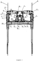
Figure 1 is a three-dimensional schematic diagram of a garden tool of a first preferred embodiment of the present invention. -
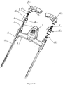
Figure 2 is a three-dimensional exploded view of an operating control mechanism fromfigure 1 . -
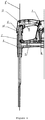
Figure 3 is a sectional view offigure 2 in an assembled state. -
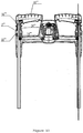
Figure 4 is a three-dimensional schematic diagram of handles of the operating control mechanism, which handles are in different rotated positions. -
Figure 5 is a three-dimensional exploded view of an operating control mechanism for a garden tool of a second preferred embodiment of the present invention. -
Figure 6 is a partial sectional view offigure 5 in an assembled state. -
Figure 7 is a three-dimensional exploded view of an operating control mechanism for a garden tool of a third preferred embodiment of the present invention. -
Figure 8 is a partial sectional view offigure 7 in an assembled state. -
Figure 9 is a three-dimensional exploded view of an operating control mechanism for a garden tool of a fourth preferred embodiment of the present invention. -
Figure 10 is a sectional view offigure 9 in an assembled state. -
Figure 11 is another sectional view offigure 9 in an assembled state. -
Figure 12 is a sectional view of a switch control mechanism of an embodiment of the present invention. -
Figure 13 is a sectional view of the switch control mechanism of the embodiment of the present invention when a trigger is pulled. -
Figure 14 is a sectional view of the switch control mechanism of the embodiment of the present invention in another state. - A non-limiting detailed description of technical solutions of the present invention is further provided below in connection with several preferred embodiments and the accompanying drawings.
- Referring to
figures 1 to 3 , a garden tool according to a preferred embodiment of the present invention is an electrical lawn mower, comprising amachine body part 10 for performing cutting work and anoperating control mechanism 20 mounted on themachine body part 10. - The
operating control mechanism 20 comprises acontrol button 7 and a pair ofhandles 12 which are arranged on two sides of thecontrol button 7. Thehandles 12 of the pair are each provided with atrigger 6, and the machine can be activated by pulling asingle trigger 6; the pair ofhandles 12 can also form a closed area with the machine body, thereby facilitating the operation. Pullropes 5 and drivinglevers 8 are arranged inside ahousing 4 of theoperating control mechanism 20, and when the machine is to be activated, thecontrol button 7 is pressed down and either of thetriggers 6 is closed, so that thedriving levers 8 are pulled by thepull ropes 5, and thus a switch is triggered. - The
operating control mechanism 20 further comprisesstop components 2 andelastic elements 3, which are movable relative to thehandles 12. Thestop components 2 are movable downwards relative to thehandles 12, and each is a hollow cylinder and provided with anoperable part 24 on an outer surface thereof. An inner surface of thestop component 2 is provided with a firsttoothed part 22, an outer surface of each of thehandles 12 is provided with a secondtoothed part 14, and the firsttoothed part 22 is engagable with the secondtoothed part 14 so as to limit and secure thestop component 2. Thehousing 4 is provided withpositioning columns 16, and thestop component 2 is arranged between thepositioning column 16 and thehandle 12. Saidelastic element 3 is sheathed on thepositioning column 16 and is arranged inside thestop component 2. - In this way, when a user needs to rotate a
handle 12, he presses downwards theoperable part 22 of thestop component 2, as shown by the arrow F, so that the engagement between the firsttoothed part 22 of thestop component 2 and the secondtoothed part 14 of thehandle 12 is released and thus thehandle 12 can rotate around the longitudinal rotational axis A thereof in a range of 360 degrees, as shown infigure 4 . When thehandle 12 is rotated to an appropriate position, theoperable part 22 of thestop component 2 is released, so that thestop component 2 bounces upwards under a restoring force of theelastic element 3 to be engaged with thehandle 12, thus limiting and securing thehandle 12 again, in which case, thehandle 12 can reach a position which is suitable for operation by the user. - In addition, the
operating control mechanism 20 further comprises twosteel tubes 11 which are connected to two sides of themachine body part 10. Eachsteel tube 11 is provided with arotary mechanism 13 which can rotate around an axis thereof (not shown in the figures). Thesteel tube 11 runs through thepositioning column 16 and thestop component 2, so that the rigidness and strength of the connection therebetween are enhanced. - Further referring to
figures 5 and6 , in embodiment II, the operating control mechanism 20' has a structure substantially similar to that of theoperating control mechanism 20 in embodiment I, and thus identical structures are denoted with identical reference numbers and are not stated in detail, only different structures being explained and illustrated. - A stop component 2' in the present embodiment is provided with a first toothed part 22' and an operable part 24' on the outer surface thereof. An inner surface of each handle 12' is provided with a second toothed part 14' which is engagable with the first toothed part 22', and an elastic element 3' is sheathed on a
positioning column 16 and arranged between the stop component 2' and the handle 12' . Pulling the operable part 24' upwards moves the stop component 2' upwards relative to the handle 12', as shown by the arrow F' , so that the engagement between the first toothed part 22' and the second toothed part 14' is released and thus the handle 12' can rotate around the rotational axis A' thereof in a range of 360 degrees. - Further referring to
figures 7 and8 , again in embodiment III, theoperating control mechanism 20" has a structure substantially similar to those of theoperating control mechanisms 20, 20' in embodiments I and II, and thus identical structures are denoted with identical reference numbers and are not stated in detail, only different structures being explained and illustrated. - The
operating control mechanism 20" in the present embodiment compriseshandles 12",stop components 2",casing tubes 18 which are sheathed on thestop components 2",elastic elements 3" andbuttons 19. A lower end part of each of thestop components 2" is provided with a first toothed part 22', each of thecasing tubes 18 is provided with a secondtoothed part 14", and the firsttoothed part 22" is engagable with the secondtoothed part 14". Each of thecasing tubes 18 is arranged between thestop component 2" and thehandle 12". Each of theelastic elements 3" is arranged between thestop component 2" and thepositioning column 16". Thebuttons 19 are mounted on thehandles 12 and are engagable with thestop components 2". In this way, when ahandle 12" needs to be rotated, abutton 12" is pressed downwards as shown by the arrow F" such that the engagement between thestop component 2" and thecasing tube 18 is released and therefore thehandle 12" can rotate around the rotational axis A" thereof in a range of 360 degrees. - Further referring to
figures 9 to 11 , the operatingcontrol mechanism 20"' of the present embodiment has a structure substantially similar to those of the operatingcontrol mechanisms - The operating
control mechanism 20"' in the present embodiment compriseshandles 12"', stopcomponents 2"', a pair ofelastic elements 3"' and casing tubes 18'. An outer surface of each of thestop components 2"' is also provided with anoperable part 24" which is used for pulling thestop component 2" upwards in the F"' direction, and the stop component is arranged between ahandle 12"' and apositioning column 16"'. An inner surface of each of thestop components 2"' is provided with a firsttoothed part 22"', and an outer surface of the bottom end of eachpositioning column 16"' is provided with a secondtoothed part 14"' which is engagable with the firsttoothed part 22"'. The casing tubes 18' are sheathed on thepositioning columns 16"' and are arranged inside thehandles 12"'. The pair ofelastic elements 3"' is arranged between thestop components 2"' and the handles 12'''. When ahandle 12"' needs to be rotated, pulling theoperable part 24"" upwards moves thestop component 2"' upwards relative to thehandle 12"', as shown by the arrow F"', so that the engagement between the firsttoothed part 22"' and the secondtoothed part 14"' is released and thus thehandle 12"' can rotate around the rotational axis A"' thereof in a range of 360 degrees. - The switch control mechanism for a garden tool in the embodiments is further described below. Referring to
figures 3 and12-14 , the switch control mechanism comprises aswitch 91, drivinglevers 8, pullropes 5 and handles 12, wherein theswitch 91 is arranged in thehousing 4, and theswitch 91 can control the opening and closing of an electrical circuit of the garden tool. The driving levers 8 are arranged on two sides of theswitch 91, the drivinglevers 8 can rotate around arotary shaft 82, and one end part of each of the driving levers 81 is provided with afirst clamping groove 81. Each of thehandles 12 is provided with amovable trigger 6, thetrigger 6 is provided with asecond clamping groove 61, and thetrigger 6 is connected to the drivinglever 8 by means of thepull rope 5; of course, thepull rope 5 can be made of any material as long as it can withstand a certain pulling force; two ends of thepull rope 5 are respectively provided with acooperative part 52, thecooperative parts 52 are respectively arranged in thefirst clamping groove 81 and thesecond clamping groove 61, a contact surface between thecooperative part 52 and a connection part of thetrigger 6 is a spherical surface, i.e., the contact surface between thecooperative part 52 and the inside of thesecond clamping groove 61 is a spherical surface, and the center of the spherical surface is on the rotational axis A, A', A", A"' of thehandle 12; thepull rope 51 at least partially overlaps the rotational axis A, A', A", A"', and thecooperative parts 52 on two ends of the pull rope in the present embodiment are both in a spherical shape and are fixedly connected to the pull rope. As stated above, the cooperative part which cooperates with thefirst clamping groove 61 can be of another structure, as long as the contact surface between thecooperative part 52 and thetrigger 6 is a spherical surface. Each of thepull ropes 5 is further sheathed with aspring 51, two ends of the spring bear against the drivinglever 8 and abase 53, respectively, and thespring 51 provides a restoring force for the drivinglever 8. The switch control mechanism is further provided withrollers 100 which can fix the trajectory of thepull ropes 5 such that the pull ropes have a constant travel, while at the same time reducing the friction force between the pull ropes and the enclosure of the machine. The control principle of the switch control mechanism is as follows: atrigger 6 on ahandle 12 is pulled by a user such that the movement of thetrigger 6 drives, by means of thepull rope 5, the drivinglever 8 to rotate, and the drivinglever 8 is moved from position M to position N, thus triggering theswitch 91, so that the electrical circuit of the garden tool is closed; since thecooperative part 52 of thepull rope 5 is in spherical-surface contact with thetrigger 6, there is a relative rotation between thecooperative part 52 and thetrigger 6 when thehandle 12 is rotated, thereby preventing thepull rope 5 from rotating along with thehandle 12. Therefore, regardless of the position into which thehandle 12 is rotated, the connection between the drivinglever 8 and thetrigger 6 is not influenced, and the machine can be controlled by the user. When thetrigger 6 is released by the user, thespring 51 provides a restoring force for the drivinglever 8, such that the drivinglever 8 is returned from position N to position M, and theswitch 91 opens the electrical circuit. - Further, in order to make the garden tool more safe to operate, the switch control mechanism can further comprise a
control button 7 which is arranged on thehousing 4, with atongue part 71 being arranged inside thecontrol button 7 and rotatable around abutton shaft 72.Figure 12 is a schematic diagram, with thetrigger 6 and thecontrol button 7 being not pressed, in which case, atrigger end 83 of each drivinglever 8 is at a distance from theswitch 91, and only thetrigger 6 is operated (as shown infigure 13 ), and at this point, the drivinglever 8 is driven into rotation by thetrigger 6, while thetrigger end 83 is still at a distance from theswitch 91 and cannot trigger theswitch 91; such a design is to avoid damage due to a misoperation by a user. Therefore, thecontrol button 7 should be firstly pressed by the user such that thetongue part 71 protrudes forwards, and at this point, thetrigger 6 is then operated, thetrigger 6 drives the drivinglever 8, thetrigger end 83 of the drivinglever 8 bears against thetongue part 71, and thetongue part 71 rotates to trigger theswitch 91, so that the electrical circuit of the garden tool is closed; this design provides higher safety for the user when operating the machine. - It should be noted that the preferred embodiments are only provided for illustrating the technical concept and characteristics of the present invention, for the purpose of enabling those skilled in the art to understand the content of the present invention and to implement the present invention, but not for limiting the scope of protection of the present invention, as defined by the appended claims.
Claims (11)
- A switch control mechanism for a garden tool, the switch control mechanism comprising handles (12) each provided with a trigger (6), a switch (91) and driving levers (8, 83) for driving the switch (91), wherein the triggers (6) are connected to the driving levers (8) via pull ropes (5), and contact surfaces between said pull ropes (5) and the triggers (6) are spherical surfaces,
characterized in that
said handles are rotatable around rotational axes (A) thereof, and the center of said spherical surface is located on the rotational axis of each of said handles, thereby preventing the pull rope (5) from rotating along with the handle (12). - The mechanism as claimed in claim 1, characterized in that said triggers are each provided with a second clamping groove (61), said pull ropes are each provided with a cooperative part (52), and said contact surface is a contact portion between said cooperative part and the second clamping groove.
- The mechanism as claimed in claim 2, characterized in that said cooperative part is spherical.
- The mechanism as claimed in claim 2, characterized in that said triggers are each provided with a first clamping groove (81), two ends of each of said pull ropes are respectively provided with said cooperative part, and said cooperative parts are respectively arranged in the first clamping groove and the second clamping groove.
- The mechanism as claimed in claim 1, characterized in that the driving levers are rotatable around rotational axes thereof, and said pull ropes are each sheathed with a spring.
- The mechanism as claimed in claim 1, characterized in that said handles and the driving levers are paired.
- The mechanism as claimed in claim 1, characterized by further comprising rollers (100), said pull ropes passing over the rollers to be connected to the driving levers and the triggers.
- The mechanism as claimed in claim 1, characterized in that said pull ropes each at least partially overlap said rotational axes.
- The mechanism as claimed in claim 1, characterized by further comprising a control button (7), said control button being arranged on a housing of the switch control mechanism housing for a garden tool.
- The mechanism as claimed in claim 9, characterized in that said control button is provided with a tongue part (71), and said tongue part protrudes above the switch when the control button is pressed.
- The mechanism as claimed in claim 10, characterized in that said driving levers are each provided with a trigger end (83) which is arranged above the tongue part.
Applications Claiming Priority (2)
| Application Number | Priority Date | Filing Date | Title |
|---|---|---|---|
| CN201310028825.XA CN103959990B (en) | 2013-01-25 | 2013-01-25 | The switching control mechanism of garden instrument |
| PCT/CN2014/070905 WO2014114217A1 (en) | 2013-01-25 | 2014-01-20 | Switch control mechanism for garden tool |
Publications (3)
| Publication Number | Publication Date |
|---|---|
| EP2949196A1 EP2949196A1 (en) | 2015-12-02 |
| EP2949196A4 EP2949196A4 (en) | 2016-10-19 |
| EP2949196B1 true EP2949196B1 (en) | 2019-07-17 |
Family
ID=51226927
Family Applications (1)
| Application Number | Title | Priority Date | Filing Date |
|---|---|---|---|
| EP14743119.1A Active EP2949196B1 (en) | 2013-01-25 | 2014-01-20 | Switch control mechanism for garden tool |
Country Status (5)
| Country | Link |
|---|---|
| US (1) | US9717177B2 (en) |
| EP (1) | EP2949196B1 (en) |
| CN (1) | CN103959990B (en) |
| CA (1) | CA2898941C (en) |
| WO (1) | WO2014114217A1 (en) |
Families Citing this family (18)
| Publication number | Priority date | Publication date | Assignee | Title |
|---|---|---|---|---|
| CN103039183B (en) * | 2013-01-25 | 2015-09-30 | 天佑电器(苏州)有限公司 | The operation controlling organization of garden instrument |
| CN106171253B (en) * | 2015-05-05 | 2020-06-23 | 南京德朔实业有限公司 | Grass cutter |
| JP2018088832A (en) * | 2016-11-30 | 2018-06-14 | 本田技研工業株式会社 | Work machine |
| JP2018085980A (en) * | 2016-11-30 | 2018-06-07 | 本田技研工業株式会社 | Electric working machine |
| US10588257B2 (en) * | 2017-10-06 | 2020-03-17 | Black & Decker, Inc. | Pivoting handle assembly |
| US20200245549A1 (en) * | 2017-10-24 | 2020-08-06 | Suzhou Cleva Precision Machinery & Technology Co., Ltd. | Gardening Tool |
| EP3549424B1 (en) | 2018-04-06 | 2022-01-05 | Lg Electronics Inc. | Lawn mower robot |
| US11140820B2 (en) * | 2018-04-06 | 2021-10-12 | Lg Electronics Inc. | Lawn mower robot |
| US11166409B2 (en) | 2018-04-06 | 2021-11-09 | Lg Electronics Inc. | Lawn mower robot |
| EP3549423B1 (en) | 2018-04-06 | 2021-06-16 | Lg Electronics Inc. | Lawn mower robot |
| EP3560312B1 (en) | 2018-04-06 | 2021-10-20 | LG Electronics Inc. | Lawn mower robot |
| EP3549426B1 (en) | 2018-04-06 | 2021-09-08 | LG Electronics Inc. | Lawn mower robot |
| EP3549425B1 (en) | 2018-04-06 | 2021-08-04 | LG Electronics Inc. | Lawn mower robot |
| EP3549427B1 (en) | 2018-04-06 | 2021-09-01 | LG Electronics Inc. | Lawn mower robot |
| CN110495302B (en) * | 2018-12-20 | 2022-08-19 | 格力博(江苏)股份有限公司 | Control box and garden tool with same |
| CN109997517A (en) * | 2019-01-16 | 2019-07-12 | 浙江亚特电器有限公司 | A kind of starter and grass trimmer for gardens electric tool |
| CN210183931U (en) * | 2019-04-16 | 2020-03-27 | 江苏苏美达五金工具有限公司 | Double-handle speed regulating mechanism and mower |
| US12279552B2 (en) | 2021-12-08 | 2025-04-22 | Honda Motor Co., Ltd. | Blade control assembly, lawnmower, and method for operating a blade control assembly |
Family Cites Families (23)
| Publication number | Priority date | Publication date | Assignee | Title |
|---|---|---|---|---|
| US2689620A (en) * | 1949-09-06 | 1954-09-21 | Oscar T Hainke | Driving assembly for lawn mowers |
| US3852944A (en) * | 1973-05-07 | 1974-12-10 | Copper Mfg Co | Lawn edger |
| US4033098A (en) * | 1975-05-30 | 1977-07-05 | Green Garry J | Grass trimming apparatus |
| US4326368A (en) * | 1980-06-12 | 1982-04-27 | Hoffco, Inc. | Clutch and brake for rotary lawn mower |
| EP0047416B2 (en) * | 1980-09-04 | 1988-07-27 | Wolf-Geräte GmbH | Safety switch device for an electric lawn mower |
| US5088273A (en) * | 1990-12-21 | 1992-02-18 | Briggs & Stratton Corporation | Lawnmower handle assembly |
| US5826667A (en) * | 1993-06-09 | 1998-10-27 | Notaras; John Arthur | Lawn edger |
| CN1060123C (en) * | 1996-06-11 | 2001-01-03 | 好孩子集团公司 | Bevel push handle rotation device of bevel shallow |
| GB2340721A (en) * | 1998-08-28 | 2000-03-01 | Black & Decker Inc | Lever switch with safety interlock. |
| JP3921026B2 (en) * | 2000-03-31 | 2007-05-30 | 石川島芝浦機械株式会社 | Mowing blade clutch mechanism of lawn mower |
| US7237620B2 (en) * | 2002-03-11 | 2007-07-03 | Desa Ip, Llc | Electric garden tiller |
| CN2696951Y (en) * | 2004-03-20 | 2005-05-04 | 中山市隆成日用制品有限公司 | Rotating structure of a handle of a stroller |
| CN2764127Y (en) * | 2004-11-16 | 2006-03-15 | 苏州太湖企业有限公司 | Grass cutter handle switch device |
| DE202004019453U1 (en) * | 2004-12-16 | 2006-04-20 | Hans Einhell Ag | Control handle for lawnmowers comprises cross-bar mounted on top of telescopic uprights, handgrips being fitted at either end of cross-bar and control switch partially built into one of these |
| CN2812537Y (en) * | 2005-07-20 | 2006-09-06 | 浙江恒泰皇冠园林工具有限公司 | Rotary handle for hay mower |
| CN201027791Y (en) * | 2006-12-08 | 2008-02-27 | 钱高法 | Soft shaft of push/pull cable |
| WO2010030281A1 (en) * | 2008-09-12 | 2010-03-18 | Husqvarna U.S. Holding, Inc. | Mower with adjustable hand grips and partially enclosed operator present switch |
| US8312946B2 (en) * | 2009-07-02 | 2012-11-20 | Husqvarna Consumer Outdoor Products N.A., Inc. | Trigger controller |
| WO2011131031A1 (en) * | 2010-04-21 | 2011-10-27 | 苏州宝时得电动工具有限公司 | Mower and controlling method for controlling its self-driven operation |
| CN202276645U (en) * | 2011-07-08 | 2012-06-20 | 天佑电器(苏州)有限公司 | Garden tool |
| JP5793360B2 (en) * | 2011-07-12 | 2015-10-14 | 株式会社マキタ | Rechargeable tiller |
| US8978796B2 (en) * | 2012-01-06 | 2015-03-17 | Silvio Gallazzini | Tractor having dual hydrostatic drive with single hand control and attachment adapter for powered attachments |
| CN203120484U (en) * | 2013-01-25 | 2013-08-14 | 天佑电器(苏州)有限公司 | On-off control mechanism of gardening tool |
-
2013
- 2013-01-25 CN CN201310028825.XA patent/CN103959990B/en active Active
-
2014
- 2014-01-20 EP EP14743119.1A patent/EP2949196B1/en active Active
- 2014-01-20 WO PCT/CN2014/070905 patent/WO2014114217A1/en not_active Ceased
- 2014-01-20 CA CA2898941A patent/CA2898941C/en not_active Expired - Fee Related
-
2015
- 2015-07-21 US US14/804,694 patent/US9717177B2/en not_active Expired - Fee Related
Non-Patent Citations (1)
| Title |
|---|
| None * |
Also Published As
| Publication number | Publication date |
|---|---|
| CA2898941C (en) | 2018-12-18 |
| CN103959990B (en) | 2016-04-13 |
| EP2949196A1 (en) | 2015-12-02 |
| EP2949196A4 (en) | 2016-10-19 |
| US20160000007A1 (en) | 2016-01-07 |
| US9717177B2 (en) | 2017-08-01 |
| CA2898941A1 (en) | 2014-07-31 |
| WO2014114217A1 (en) | 2014-07-31 |
| CN103959990A (en) | 2014-08-06 |
Similar Documents
| Publication | Publication Date | Title |
|---|---|---|
| US9717177B2 (en) | Switch control mechanism for garden tool | |
| CA2898940C (en) | Operating control mechanism for garden tool | |
| RU2522527C2 (en) | Drive tool | |
| CN103168632B (en) | Vegetation cutting device | |
| DE102014006910B4 (en) | green waste Schneider | |
| CN204616397U (en) | Mower | |
| CN101584288B (en) | Handheld tool | |
| CN102396351B (en) | Pruner and switch device thereof | |
| CN102528155B (en) | Electric circular saw provided with switch protection mechanism | |
| CN201226692Y (en) | Hand tool | |
| EP3141357B1 (en) | Electric scissors | |
| CN104641960A (en) | Pruning machine | |
| CN104206193A (en) | Pruning shears with rotatable handle | |
| CN109047909B (en) | A kind of control structure of electric circular saw | |
| AU2011101131A4 (en) | Hedge Trimmer And Switch Device Thereof | |
| CN121890430A (en) | Hedge trimmer | |
| CN102047815B (en) | Pruning shear | |
| CN208300389U (en) | The changeable shrub and hedge trimmer of operative orientation | |
| CN206961735U (en) | Control panel and the garden instrument using the panel | |
| JP2002171833A (en) | Hedge trimmer | |
| CN203261834U (en) | Hedge trimmer with rotatable handle | |
| CN204616418U (en) | mower | |
| CN203120484U (en) | On-off control mechanism of gardening tool | |
| CN101336600B (en) | Pruning shears with rotatable rear handle | |
| GB2340721A (en) | Lever switch with safety interlock. |
Legal Events
| Date | Code | Title | Description |
|---|---|---|---|
| PUAI | Public reference made under article 153(3) epc to a published international application that has entered the european phase |
Free format text: ORIGINAL CODE: 0009012 |
|
| 17P | Request for examination filed |
Effective date: 20150825 |
|
| AK | Designated contracting states |
Kind code of ref document: A1 Designated state(s): AL AT BE BG CH CY CZ DE DK EE ES FI FR GB GR HR HU IE IS IT LI LT LU LV MC MK MT NL NO PL PT RO RS SE SI SK SM TR |
|
| AX | Request for extension of the european patent |
Extension state: BA ME |
|
| DAX | Request for extension of the european patent (deleted) | ||
| REG | Reference to a national code |
Ref country code: DE Ref legal event code: R079 Ref document number: 602014050142 Country of ref document: DE Free format text: PREVIOUS MAIN CLASS: A01D0034000000 Ipc: A01D0034820000 |
|
| A4 | Supplementary search report drawn up and despatched |
Effective date: 20160916 |
|
| RIC1 | Information provided on ipc code assigned before grant |
Ipc: A01D 34/82 20060101AFI20160912BHEP |
|
| GRAP | Despatch of communication of intention to grant a patent |
Free format text: ORIGINAL CODE: EPIDOSNIGR1 |
|
| STAA | Information on the status of an ep patent application or granted ep patent |
Free format text: STATUS: GRANT OF PATENT IS INTENDED |
|
| INTG | Intention to grant announced |
Effective date: 20190206 |
|
| GRAS | Grant fee paid |
Free format text: ORIGINAL CODE: EPIDOSNIGR3 |
|
| GRAA | (expected) grant |
Free format text: ORIGINAL CODE: 0009210 |
|
| STAA | Information on the status of an ep patent application or granted ep patent |
Free format text: STATUS: THE PATENT HAS BEEN GRANTED |
|
| AK | Designated contracting states |
Kind code of ref document: B1 Designated state(s): AL AT BE BG CH CY CZ DE DK EE ES FI FR GB GR HR HU IE IS IT LI LT LU LV MC MK MT NL NO PL PT RO RS SE SI SK SM TR |
|
| REG | Reference to a national code |
Ref country code: GB Ref legal event code: FG4D |
|
| REG | Reference to a national code |
Ref country code: CH Ref legal event code: EP |
|
| REG | Reference to a national code |
Ref country code: IE Ref legal event code: FG4D |
|
| REG | Reference to a national code |
Ref country code: DE Ref legal event code: R096 Ref document number: 602014050142 Country of ref document: DE |
|
| REG | Reference to a national code |
Ref country code: AT Ref legal event code: REF Ref document number: 1154968 Country of ref document: AT Kind code of ref document: T Effective date: 20190815 |
|
| REG | Reference to a national code |
Ref country code: NL Ref legal event code: MP Effective date: 20190717 |
|
| REG | Reference to a national code |
Ref country code: LT Ref legal event code: MG4D |
|
| REG | Reference to a national code |
Ref country code: AT Ref legal event code: MK05 Ref document number: 1154968 Country of ref document: AT Kind code of ref document: T Effective date: 20190717 |
|
| PG25 | Lapsed in a contracting state [announced via postgrant information from national office to epo] |
Ref country code: AT Free format text: LAPSE BECAUSE OF FAILURE TO SUBMIT A TRANSLATION OF THE DESCRIPTION OR TO PAY THE FEE WITHIN THE PRESCRIBED TIME-LIMIT Effective date: 20190717 Ref country code: BG Free format text: LAPSE BECAUSE OF FAILURE TO SUBMIT A TRANSLATION OF THE DESCRIPTION OR TO PAY THE FEE WITHIN THE PRESCRIBED TIME-LIMIT Effective date: 20191017 Ref country code: NO Free format text: LAPSE BECAUSE OF FAILURE TO SUBMIT A TRANSLATION OF THE DESCRIPTION OR TO PAY THE FEE WITHIN THE PRESCRIBED TIME-LIMIT Effective date: 20191017 Ref country code: HR Free format text: LAPSE BECAUSE OF FAILURE TO SUBMIT A TRANSLATION OF THE DESCRIPTION OR TO PAY THE FEE WITHIN THE PRESCRIBED TIME-LIMIT Effective date: 20190717 Ref country code: SE Free format text: LAPSE BECAUSE OF FAILURE TO SUBMIT A TRANSLATION OF THE DESCRIPTION OR TO PAY THE FEE WITHIN THE PRESCRIBED TIME-LIMIT Effective date: 20190717 Ref country code: PT Free format text: LAPSE BECAUSE OF FAILURE TO SUBMIT A TRANSLATION OF THE DESCRIPTION OR TO PAY THE FEE WITHIN THE PRESCRIBED TIME-LIMIT Effective date: 20191118 Ref country code: FI Free format text: LAPSE BECAUSE OF FAILURE TO SUBMIT A TRANSLATION OF THE DESCRIPTION OR TO PAY THE FEE WITHIN THE PRESCRIBED TIME-LIMIT Effective date: 20190717 Ref country code: NL Free format text: LAPSE BECAUSE OF FAILURE TO SUBMIT A TRANSLATION OF THE DESCRIPTION OR TO PAY THE FEE WITHIN THE PRESCRIBED TIME-LIMIT Effective date: 20190717 Ref country code: LT Free format text: LAPSE BECAUSE OF FAILURE TO SUBMIT A TRANSLATION OF THE DESCRIPTION OR TO PAY THE FEE WITHIN THE PRESCRIBED TIME-LIMIT Effective date: 20190717 |
|
| PG25 | Lapsed in a contracting state [announced via postgrant information from national office to epo] |
Ref country code: RS Free format text: LAPSE BECAUSE OF FAILURE TO SUBMIT A TRANSLATION OF THE DESCRIPTION OR TO PAY THE FEE WITHIN THE PRESCRIBED TIME-LIMIT Effective date: 20190717 Ref country code: AL Free format text: LAPSE BECAUSE OF FAILURE TO SUBMIT A TRANSLATION OF THE DESCRIPTION OR TO PAY THE FEE WITHIN THE PRESCRIBED TIME-LIMIT Effective date: 20190717 Ref country code: GR Free format text: LAPSE BECAUSE OF FAILURE TO SUBMIT A TRANSLATION OF THE DESCRIPTION OR TO PAY THE FEE WITHIN THE PRESCRIBED TIME-LIMIT Effective date: 20191018 Ref country code: ES Free format text: LAPSE BECAUSE OF FAILURE TO SUBMIT A TRANSLATION OF THE DESCRIPTION OR TO PAY THE FEE WITHIN THE PRESCRIBED TIME-LIMIT Effective date: 20190717 Ref country code: LV Free format text: LAPSE BECAUSE OF FAILURE TO SUBMIT A TRANSLATION OF THE DESCRIPTION OR TO PAY THE FEE WITHIN THE PRESCRIBED TIME-LIMIT Effective date: 20190717 Ref country code: IS Free format text: LAPSE BECAUSE OF FAILURE TO SUBMIT A TRANSLATION OF THE DESCRIPTION OR TO PAY THE FEE WITHIN THE PRESCRIBED TIME-LIMIT Effective date: 20191117 |
|
| PG25 | Lapsed in a contracting state [announced via postgrant information from national office to epo] |
Ref country code: TR Free format text: LAPSE BECAUSE OF FAILURE TO SUBMIT A TRANSLATION OF THE DESCRIPTION OR TO PAY THE FEE WITHIN THE PRESCRIBED TIME-LIMIT Effective date: 20190717 |
|
| PG25 | Lapsed in a contracting state [announced via postgrant information from national office to epo] |
Ref country code: IT Free format text: LAPSE BECAUSE OF FAILURE TO SUBMIT A TRANSLATION OF THE DESCRIPTION OR TO PAY THE FEE WITHIN THE PRESCRIBED TIME-LIMIT Effective date: 20190717 Ref country code: RO Free format text: LAPSE BECAUSE OF FAILURE TO SUBMIT A TRANSLATION OF THE DESCRIPTION OR TO PAY THE FEE WITHIN THE PRESCRIBED TIME-LIMIT Effective date: 20190717 Ref country code: EE Free format text: LAPSE BECAUSE OF FAILURE TO SUBMIT A TRANSLATION OF THE DESCRIPTION OR TO PAY THE FEE WITHIN THE PRESCRIBED TIME-LIMIT Effective date: 20190717 Ref country code: PL Free format text: LAPSE BECAUSE OF FAILURE TO SUBMIT A TRANSLATION OF THE DESCRIPTION OR TO PAY THE FEE WITHIN THE PRESCRIBED TIME-LIMIT Effective date: 20190717 Ref country code: DK Free format text: LAPSE BECAUSE OF FAILURE TO SUBMIT A TRANSLATION OF THE DESCRIPTION OR TO PAY THE FEE WITHIN THE PRESCRIBED TIME-LIMIT Effective date: 20190717 |
|
| PGFP | Annual fee paid to national office [announced via postgrant information from national office to epo] |
Ref country code: DE Payment date: 20200211 Year of fee payment: 7 Ref country code: GB Payment date: 20200131 Year of fee payment: 7 |
|
| PG25 | Lapsed in a contracting state [announced via postgrant information from national office to epo] |
Ref country code: CZ Free format text: LAPSE BECAUSE OF FAILURE TO SUBMIT A TRANSLATION OF THE DESCRIPTION OR TO PAY THE FEE WITHIN THE PRESCRIBED TIME-LIMIT Effective date: 20190717 Ref country code: SK Free format text: LAPSE BECAUSE OF FAILURE TO SUBMIT A TRANSLATION OF THE DESCRIPTION OR TO PAY THE FEE WITHIN THE PRESCRIBED TIME-LIMIT Effective date: 20190717 Ref country code: IS Free format text: LAPSE BECAUSE OF FAILURE TO SUBMIT A TRANSLATION OF THE DESCRIPTION OR TO PAY THE FEE WITHIN THE PRESCRIBED TIME-LIMIT Effective date: 20200224 Ref country code: SM Free format text: LAPSE BECAUSE OF FAILURE TO SUBMIT A TRANSLATION OF THE DESCRIPTION OR TO PAY THE FEE WITHIN THE PRESCRIBED TIME-LIMIT Effective date: 20190717 |
|
| REG | Reference to a national code |
Ref country code: DE Ref legal event code: R097 Ref document number: 602014050142 Country of ref document: DE |
|
| PGFP | Annual fee paid to national office [announced via postgrant information from national office to epo] |
Ref country code: FR Payment date: 20200131 Year of fee payment: 7 |
|
| PLBE | No opposition filed within time limit |
Free format text: ORIGINAL CODE: 0009261 |
|
| STAA | Information on the status of an ep patent application or granted ep patent |
Free format text: STATUS: NO OPPOSITION FILED WITHIN TIME LIMIT |
|
| PG2D | Information on lapse in contracting state deleted |
Ref country code: IS |
|
| 26N | No opposition filed |
Effective date: 20200603 |
|
| PG25 | Lapsed in a contracting state [announced via postgrant information from national office to epo] |
Ref country code: MC Free format text: LAPSE BECAUSE OF FAILURE TO SUBMIT A TRANSLATION OF THE DESCRIPTION OR TO PAY THE FEE WITHIN THE PRESCRIBED TIME-LIMIT Effective date: 20190717 Ref country code: SI Free format text: LAPSE BECAUSE OF FAILURE TO SUBMIT A TRANSLATION OF THE DESCRIPTION OR TO PAY THE FEE WITHIN THE PRESCRIBED TIME-LIMIT Effective date: 20190717 |
|
| REG | Reference to a national code |
Ref country code: CH Ref legal event code: PL |
|
| REG | Reference to a national code |
Ref country code: BE Ref legal event code: MM Effective date: 20200131 |
|
| PG25 | Lapsed in a contracting state [announced via postgrant information from national office to epo] |
Ref country code: LU Free format text: LAPSE BECAUSE OF NON-PAYMENT OF DUE FEES Effective date: 20200120 |
|
| PG25 | Lapsed in a contracting state [announced via postgrant information from national office to epo] |
Ref country code: CH Free format text: LAPSE BECAUSE OF NON-PAYMENT OF DUE FEES Effective date: 20200131 Ref country code: LI Free format text: LAPSE BECAUSE OF NON-PAYMENT OF DUE FEES Effective date: 20200131 Ref country code: BE Free format text: LAPSE BECAUSE OF NON-PAYMENT OF DUE FEES Effective date: 20200131 |
|
| PG25 | Lapsed in a contracting state [announced via postgrant information from national office to epo] |
Ref country code: IE Free format text: LAPSE BECAUSE OF NON-PAYMENT OF DUE FEES Effective date: 20200120 |
|
| REG | Reference to a national code |
Ref country code: DE Ref legal event code: R119 Ref document number: 602014050142 Country of ref document: DE |
|
| GBPC | Gb: european patent ceased through non-payment of renewal fee |
Effective date: 20210120 |
|
| PG25 | Lapsed in a contracting state [announced via postgrant information from national office to epo] |
Ref country code: FR Free format text: LAPSE BECAUSE OF NON-PAYMENT OF DUE FEES Effective date: 20210131 |
|
| PG25 | Lapsed in a contracting state [announced via postgrant information from national office to epo] |
Ref country code: DE Free format text: LAPSE BECAUSE OF NON-PAYMENT OF DUE FEES Effective date: 20210803 Ref country code: GB Free format text: LAPSE BECAUSE OF NON-PAYMENT OF DUE FEES Effective date: 20210120 |
|
| PG25 | Lapsed in a contracting state [announced via postgrant information from national office to epo] |
Ref country code: MT Free format text: LAPSE BECAUSE OF FAILURE TO SUBMIT A TRANSLATION OF THE DESCRIPTION OR TO PAY THE FEE WITHIN THE PRESCRIBED TIME-LIMIT Effective date: 20190717 Ref country code: CY Free format text: LAPSE BECAUSE OF FAILURE TO SUBMIT A TRANSLATION OF THE DESCRIPTION OR TO PAY THE FEE WITHIN THE PRESCRIBED TIME-LIMIT Effective date: 20190717 |
|
| PG25 | Lapsed in a contracting state [announced via postgrant information from national office to epo] |
Ref country code: MK Free format text: LAPSE BECAUSE OF FAILURE TO SUBMIT A TRANSLATION OF THE DESCRIPTION OR TO PAY THE FEE WITHIN THE PRESCRIBED TIME-LIMIT Effective date: 20190717 |