EP2949087B1 - Multi-node virtual switching system - Google Patents
Multi-node virtual switching system Download PDFInfo
- Publication number
- EP2949087B1 EP2949087B1 EP14704418.4A EP14704418A EP2949087B1 EP 2949087 B1 EP2949087 B1 EP 2949087B1 EP 14704418 A EP14704418 A EP 14704418A EP 2949087 B1 EP2949087 B1 EP 2949087B1
- Authority
- EP
- European Patent Office
- Prior art keywords
- network
- switches
- leaf node
- node switches
- network domain
- Prior art date
- Legal status (The legal status is an assumption and is not a legal conclusion. Google has not performed a legal analysis and makes no representation as to the accuracy of the status listed.)
- Active
Links
Images


Classifications
-
- H—ELECTRICITY
- H04—ELECTRIC COMMUNICATION TECHNIQUE
- H04L—TRANSMISSION OF DIGITAL INFORMATION, e.g. TELEGRAPHIC COMMUNICATION
- H04L41/00—Arrangements for maintenance, administration or management of data switching networks, e.g. of packet switching networks
- H04L41/08—Configuration management of networks or network elements
- H04L41/0803—Configuration setting
-
- H—ELECTRICITY
- H04—ELECTRIC COMMUNICATION TECHNIQUE
- H04L—TRANSMISSION OF DIGITAL INFORMATION, e.g. TELEGRAPHIC COMMUNICATION
- H04L41/00—Arrangements for maintenance, administration or management of data switching networks, e.g. of packet switching networks
- H04L41/04—Network management architectures or arrangements
- H04L41/044—Network management architectures or arrangements comprising hierarchical management structures
-
- H—ELECTRICITY
- H04—ELECTRIC COMMUNICATION TECHNIQUE
- H04L—TRANSMISSION OF DIGITAL INFORMATION, e.g. TELEGRAPHIC COMMUNICATION
- H04L41/00—Arrangements for maintenance, administration or management of data switching networks, e.g. of packet switching networks
- H04L41/08—Configuration management of networks or network elements
- H04L41/0895—Configuration of virtualised networks or elements, e.g. virtualised network function or OpenFlow elements
-
- H—ELECTRICITY
- H04—ELECTRIC COMMUNICATION TECHNIQUE
- H04L—TRANSMISSION OF DIGITAL INFORMATION, e.g. TELEGRAPHIC COMMUNICATION
- H04L41/00—Arrangements for maintenance, administration or management of data switching networks, e.g. of packet switching networks
- H04L41/40—Arrangements for maintenance, administration or management of data switching networks, e.g. of packet switching networks using virtualisation of network functions or resources, e.g. SDN or NFV entities
-
- H—ELECTRICITY
- H04—ELECTRIC COMMUNICATION TECHNIQUE
- H04L—TRANSMISSION OF DIGITAL INFORMATION, e.g. TELEGRAPHIC COMMUNICATION
- H04L49/00—Packet switching elements
- H04L49/70—Virtual switches
Definitions
- VSL Virtual Switching Link
- EP 2 407 879 discloses a method for network configuration and/or provisioning based on open virtualization format (OVF) metadata that may include accessing a set of port profiles for one or more virtual machines from a port profile database based on OVF metadata, whereby one or more virtual machines may be configured, deployed, and/or managed based on the accessed set of port profiles.
- OVF open virtualization format
- multi-node virtual switching system may be provided.
- a virtual supervisor module may be configured onto a network device to serve as a single control point for a network.
- the VSM may virtualize an interconnection of switches within the network as a virtual fabric and allocate a portion of the network switches to a network domain.
- the allocated portion of network switches may be represented by the VSM as a single virtualized logical switch.
- the VSM may then manage the network domain from the single control point.
- a multi-node virtual switching system may be provided.
- Embodiments of the disclosure may overcome the limitations of the conventional VSS by creating a Virtual Fabric Network (VFN).
- VFN Virtual Fabric Network
- the VFN may enable a plurality of network switches to function as a single virtualized logical switch.
- the virtualization of the single logical switch may, in turn, facilitate the provision of single point network management.
- any single point management solution may be limited to controlling the network devices coupled to a particular switch pair.
- Single point network management in a VFN may have access to all of the network devices in a network because, for example, the VFN may interface with all of the switches in the network.
- the VFN may interface with the switches in a network with, for example, a multi-pathing technology.
- Multi-pathing technology consistent with embodiments of this disclosure may be configured to traverse the switches in a network and map their interconnections. Having mapped the switch interconnections, the VFN may then represent the interconnected switches as a single virtualized logical switch. In turn, the virtualized logical switch may facilitate the provision of a single point network management solution that may have access to any network device connected to any network switch.
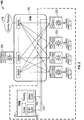
- FIG. 1 is a diagram of a network 100.
- VFN 105 may be comprised of leaf node switches 110 and spine node switches 115 interconnected in a CLOS arrangement. Spine node switches 115 may be used to interconnect leaf node switches 110 while leaf node switches 110 may be used to interface with, for example, a network device 120.
- VFN 105 may employ a multi-pathing technology to: i) traverse network 100 (i.e., leaf node switches 110 and spine node switches 115), ii) map an interconnection between all of the switching nodes, and iii) virtualize a single logical switch representing the interconnected switching nodes. As will be described in greater detail below, such virtualization may be provided from, for example, a central control station of network 100 running a Virtual Supervisor Module (VSM) 125.
- VSM Virtual Supervisor Module
- embodiments of the MVSS may emulate a point-to-point connection between the network devices connected to network 100.
- network device 120 may interface with VFN 105 via a leaf node switch.
- This leaf node switch may be represented as a virtual port of the virtualized logical switch created by VFN 105.
- VFN 105 may emulate a point-to-point connection for each network device connected to network 100 as each network device may be connected to a port of the same virtualized switch.
- VSM 125 single point network management may be provided by VSM 125.
- VSM 125 may be configured on any network device connected to any leaf node of network 100. Once configured and connected, VSM 125 may gain access to all the network switches and devices connected to VFN 105. As detailed below with reference to FIG. 2 , VSM 125 may then be operative to provide for the control and management of the network switches and devices.
- FIG. 2 illustrates VFN 105 and VSM 125 in greater detail.
- VFN 105 may virtualize network 100 by, for example, collapsing the distribution and access layers throughout network 100. Such virtualization may not be limited to campus and data centers 205, but also span across multiple distant campus and data center networks for a service provider 210. These campus and data centers 205 may be represented as nodes 220, with VFN 105 providing the transport layer (behaving as a, for example, backplane fabric of a chassis) with multi-pathing capabilities. The multi-pathing capabilities may further enable VFN 105 to provide, for example, optimal load-balancing, ease of configuration, and connectivity across multiple network topographies.
- VSM 125 may provide a virtualized network management control plane to control nodes 220 through VFN 105.
- the virtualized network management control plane may provide a look and feel of single point configuration, control, and management across the entire MVSS. For example, each node in the MVSS may be added to VSM 125's control plane as a virtual line card instance.
- VSM 125 may monitor each of its node elements and, if there are any node failures or link failures, VSM 125 may manage such failures in accordance with, for example, conventional failure handling methods.
- a standby instance of VSM 125 may be running at all times on the same or different network device as an active instance of VSM 125.
- the standby instance may be synced with the active instance by, for example, using a Check-point Framework and Redundancy Framework.
- VFN 105 and VSM 125 form the building blocks of the MVSS, with VFN 105 virtualizing the switching nodes of network 100 and VSM 125 providing a virtualized control plane for unifying the management and control of the virtualized nodes.
- the MVSS may be visualized as a virtual modular switch chassis, with VSM 125 as a supervisory entity, VFN 105 as a backplane, and nodes 220 as line card entities.
- VSM 125 may run as an iOS (dloU) module on a UCS server.
- a Virtual Control Communication Path (VCCP) 215 may provide connectivity to VSM 125 by extending an EOBC and In-Band communication channel over VFN 105.
- VCCP 215 may comprise a 1:n ether-channel having its link protected by CoPP and rate limiting.
- VFN 105 may employ an innovative multi-pathing communication protocol to interconnect all the nodes in the MVSS.
- FIG. 3 illustrates a frame 300 in a VFN communication protocol.
- Frame 300 may comprise, but not be limited to, a tunnel header 305, a VFN label 310, an optional segment label 315, and an L2 frame 320.
- tunnel header 305 may specify a destination and be read to forward packets in VFN 105 to the specified destination.
- VFN label 310 may provide a switch ID and a VLAN ID to identify a specific virtual switch node and the VLAN associated with the virtual switch node.
- Optional segment label 315 may be used in a multi-tenant environment.
- VSM 125 may be configured to segment VFN 105 into a plurality of network domains.
- segment label 315 multiple instances of VFN 105 may be carved out of the MVSS.
- Either VFN label 310 or segment label 315 may be statically assigned or distributed using protocols such as a label distribution protocol (LDP).
- LDP label distribution protocol
- VFN 105 may provide plug-and-play capability in any one of its segmented network domains.
- FIG. 4 is a flow chart setting forth the general stages involved in a method 400 consistent with an embodiment of the disclosure.
- Method 400 may be implemented using, for example, network device 120 and/or VSM 125.
- Network device 120 is described in more detail below with respect to FIG. 5 .
- Ways to implement the stages of method 400 will be described with reference to VSM 125 for illustrative purposes, though other devices, such as network device 120, may be implemented.
- Method 400 may begin at starting block 405 and proceed to stage 410 where VSM 125 may be configured onto a leaf node switch 110 of network 100.
- VSM 125 may be configured onto any leaf node switch of network 100 and provide a single network control point solution from that leaf node switch.
- the leaf node switch 110 may be coupled to, for example, network device 120.
- Network device 120 may be a standalone system specifically configured to run VSM 125.
- network device 120 may be any server capable of operating a network management console.
- VSM 125 may virtualize an interconnection of network switches as a virtual fabric. For example, having been configured at leaf node switch 110, VSM 125 may then be operative to traverse network 100 and map all of the interconnections of the leaf node switches 110 and spine node switches 115. Having mapped the interconnected switches, VSM 125 may model the switch interconnections as a virtual fabric to form VFN 105.
- This virtual fabric may employ multi-pathing technology to provide a transport layer backplane for network 100, resembling the functionality of actual modular switch chassis fabric.
- VSM 125 may be configured to automatically discover connected network devices and provide, in addition to other single point network management solutions, the connected devices with a virtualized point-to-point network connection.
- VSM 125 may allocate a portion of the network switches to a network domain. Consistent with single point network management solutions of this disclosure, VSM 125 may provide a network administrator with the functionality of segmenting leaf node switches 110 into a particular network domain. Though no physical changes to the switch interconnections occur, VSM 125 employs the VFN 105 in routing packets of information through network 100 as if separate network domains exist in isolation.
- VSM 125 may allocate a first portion of leaf node switches 110 to a first network domain and a second portion of the leaf node switches 110 to a second network domain. Similarly, VSM 125 may provide network administrators with the functionality of dynamically reallocating leaf node switches from the first network domain to the second network domain.
- spine nodes 115 may remain undedicated to any network domain to equalize a bandwidth of VFN 105 across various network domains. Accordingly, the bandwidth (or "fabric capacity") for VFN 105 may be extended upon an addition of spine node switches 115.
- VSM 125 may represent the portion of network switches as a single logical switch for the network domain.
- VSM 125 may model the allocated leaf node switches as ports of the virtualized logical switch.
- a network device connected to a leaf node switch may be, in turn, configured to a virtual port of the virtualized logical switch.
- network domain's capacity for network devices may be known as "port density" and be proportionally related to an amount of leaf node switches 110 allocated to the network domain.
- each network domain and its corresponding allocated leaf node switches 110 may be virtualized as a separate logical switch and have a sub-VSM configured within that domain.
- VFN 105 may be controlled by a master VSM, each sub-VSM may be configured to have the same functionality as VSM 125.
- VSM 125 represents the single logical switch in stage 440, method 400 may then end at stage 450.
- An embodiment consistent with the disclosure may comprise an apparatus for performing a method.
- the apparatus may comprise a memory storage and a processing unit coupled to the memory storage.
- the processing unit may be operative to connect to a network comprised of a plurality of switches; virtualize a fabric corresponding to an interconnection of the plurality of switches; allocate at least a portion of the plurality of network switches to a network domain; and represent, using the virtualized fabric, the portion of the plurality of switches as a single logical switch.
- the apparatus may comprise a memory storage and a processing unit coupled to the memory storage.
- the processing unit may be operative to configure a first virtual supervisor module onto to a first switch of a network comprised of a plurality of switches; virtualize an interconnection of the plurality of switches as a virtual fabric; allocate, via the first virtual supervisor module, a first portion of the plurality of switches to a first network domain; and represent, by way of the virtualized interconnection, the first portion of the plurality of switches as a first virtualized logical switch.
- the system may comprise a plurality of interconnected network switches comprising spine node switches and leaf node switches, wherein the spine node switches interconnect the leaf node switches; a plurality of network devices connected to the network via the leaf node switches; and a single control point connected to the network via one of the leaf node switches, single control point being configured to: virtualize the interconnection of the plurality of interconnected network switches as a virtual fabric, and represent, via the virtual fabric, the interconnection of the plurality of interconnected network switches a single logical switch.
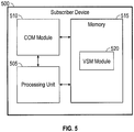
- FIG. 5 is a block diagram of a network device 500.
- Network device 500 may be a computing device or any other type of networking device, such as network devices 120.
- Network device 500 may comprise, for example, an operating environment for network devices 120 and VSM 125.
- Network device 500 may comprise a processing unit 505 operatively tied to a communication module 510, and a memory 515.
- Communication module 510 may provide communications over, for example, network 100 in a distributed computing environment.
- communication processes interfacing with communication module 510 may include wired processes such as a wired network or direct-wired connection, and wireless processes such as acoustic, radio frequency (RF), infrared, and other wireless media.
- RF radio frequency
- Memory 515 may comprise any computer storage media, such as volatile and nonvolatile, removable and non-removable media implemented in any method or technology for storage of information, such as computer readable instructions, data structures, program modules, or other data.
- Computer storage media may include, but is not limited to, random access memory (RAM), read only memory (ROM), electrically erasable read-only memory (EEPROM), flash memory or other memory technology, CD-ROM, digital versatile disks (DVD) or other optical storage, magnetic cassettes, magnetic tape, magnetic disk storage or other magnetic storage devices, or any other medium which can be used to store information and which can be accessed by network device 500. Any such computer storage media may be part of network device 500.
- the term computer readable media as used herein may include both storage media and communication media.
- Memory 515 may store, for example, an operating system and one or more programming modules.
- the operating system for example, may be suitable for controlling network device 500's operation.
- memory 515 of network device 500 may comprise a VSM module 125.
- VSM module 125 may perform, for example, one or more stages from method 400 described with respect to FIG. 4 .
- network device 500 is shown to have the aforementioned components, other components may be included in network device 500 such as input/output components, display components, and other components.
- Embodiments of the disclosure are described above with reference to block diagrams and/or operational illustrations of methods, systems, and computer program products.
- the functions/acts noted in the blocks may occur out of the order as shown in any flowchart.
- two blocks shown in succession may in fact be executed substantially concurrently or the blocks may sometimes be executed in the reverse order, depending upon the functionality/acts involved.
Landscapes
- Engineering & Computer Science (AREA)
- Computer Networks & Wireless Communication (AREA)
- Signal Processing (AREA)
- Data Exchanges In Wide-Area Networks (AREA)
Description
- Virtualizing networking devices and providing single point network management to virtualized networked devices is an emerging challenge facing network providers today. Conventional Virtual Switching Systems (VSS) may virtualize two physical switches into one switch by extending the switching fabric through a point-to- point link, known as a Virtual Switching Link (VSL). The VSL, however, limits conventional VSS to the aggregation of only two switches. Consequently, scaling this conventional model to large networks may limit virtual switching capacity and, in turn, single point network management.
-
EP 2 407 879 discloses a method for network configuration and/or provisioning based on open virtualization format (OVF) metadata that may include accessing a set of port profiles for one or more virtual machines from a port profile database based on OVF metadata, whereby one or more virtual machines may be configured, deployed, and/or managed based on the accessed set of port profiles. - The accompanying drawings, which are incorporated in and constitute a part of this disclosure, illustrate various embodiments of the present disclosure. In the drawings:
-
FIG. 1 is a diagram of a network; -
FIG. 2 is another diagram of the network; -
FIG. 3 is an example of a network frame; -
FIG. 4 is a flow chart of a method; and -
FIG. 5 is one embodiment of a network device. - The invention is defined by the independent claims. Embodiments are defined by the dependent claims. multi-node virtual switching system (MVSS) may be provided. A virtual supervisor module (VSM) may be configured onto a network device to serve as a single control point for a network. The VSM may virtualize an interconnection of switches within the network as a virtual fabric and allocate a portion of the network switches to a network domain. The allocated portion of network switches may be represented by the VSM as a single virtualized logical switch. The VSM may then manage the network domain from the single control point.
- Both the foregoing overview and the following example embodiment are examples and explanatory only, and should not be considered to restrict the disclosure's scope, as described and claimed. Further, features and/or variations may be provided in addition to those set forth herein. For example, embodiments of the disclosure may be directed to various feature combinations and sub-combinations described in the example embodiments.
- The following detailed description refers to the accompanying drawings. Wherever possible, the same reference numbers are used in the drawings and the following description to refer to the same or similar elements. While embodiments may be described, modifications, adaptations, and other implementations are possible. For example, substitutions, additions, or modifications may be made to the elements illustrated in the drawings, and the methods described herein may be modified by substituting, reordering, or adding stages to the disclosed methods. Accordingly, the following detailed description does not limit the disclosure.
- A multi-node virtual switching system (MVSS) may be provided. Embodiments of the disclosure may overcome the limitations of the conventional VSS by creating a Virtual Fabric Network (VFN). As will be described in greater detail below, the VFN may enable a plurality of network switches to function as a single virtualized logical switch. The virtualization of the single logical switch may, in turn, facilitate the provision of single point network management.
- In conventional VSS technology, single point network management is inhibited by the technology's limited switch aggregation capacity. For instance, since conventional VSS technology may only aggregate switches in pairs, any single point management solution may be limited to controlling the network devices coupled to a particular switch pair. Single point network management in a VFN, however, may have access to all of the network devices in a network because, for example, the VFN may interface with all of the switches in the network.
- The VFN may interface with the switches in a network with, for example, a multi-pathing technology. Multi-pathing technology consistent with embodiments of this disclosure may be configured to traverse the switches in a network and map their interconnections. Having mapped the switch interconnections, the VFN may then represent the interconnected switches as a single virtualized logical switch. In turn, the virtualized logical switch may facilitate the provision of a single point network management solution that may have access to any network device connected to any network switch.
-
FIG. 1 is a diagram of anetwork 100. VFN 105 may be comprised ofleaf node switches 110 andspine node switches 115 interconnected in a CLOS arrangement.Spine node switches 115 may be used to interconnectleaf node switches 110 whileleaf node switches 110 may be used to interface with, for example, anetwork device 120. As mentioned above, VFN 105 may employ a multi-pathing technology to: i) traverse network 100 (i.e.,leaf node switches 110 and spine node switches 115), ii) map an interconnection between all of the switching nodes, and iii) virtualize a single logical switch representing the interconnected switching nodes. As will be described in greater detail below, such virtualization may be provided from, for example, a central control station ofnetwork 100 running a Virtual Supervisor Module (VSM) 125. - Having virtualized the network switches as a single logical switch, embodiments of the MVSS may emulate a point-to-point connection between the network devices connected to
network 100. For example,network device 120 may interface with VFN 105 via a leaf node switch. This leaf node switch may be represented as a virtual port of the virtualized logical switch created by VFN 105. Accordingly, whennetwork device 120 is connected to the leaf node switch, its connection to VFN 105 may be represented by a connection to a corresponding virtual port of the virtualized logical switch. In this way, VFN 105 may emulate a point-to-point connection for each network device connected tonetwork 100 as each network device may be connected to a port of the same virtualized switch. - Consistent with embodiments of the MVSS, single point network management may be provided by VSM 125. For example, VSM 125 may be configured on any network device connected to any leaf node of
network 100. Once configured and connected, VSM 125 may gain access to all the network switches and devices connected to VFN 105. As detailed below with reference toFIG. 2 , VSM 125 may then be operative to provide for the control and management of the network switches and devices. -
FIG. 2 illustrates VFN 105 and VSM 125 in greater detail. VFN 105 may virtualizenetwork 100 by, for example, collapsing the distribution and access layers throughoutnetwork 100. Such virtualization may not be limited to campus anddata centers 205, but also span across multiple distant campus and data center networks for aservice provider 210. These campus anddata centers 205 may be represented asnodes 220, with VFN 105 providing the transport layer (behaving as a, for example, backplane fabric of a chassis) with multi-pathing capabilities. The multi-pathing capabilities may further enable VFN 105 to provide, for example, optimal load-balancing, ease of configuration, and connectivity across multiple network topographies. - Consistent with embodiments of the disclosure, VSM 125 may provide a virtualized network management control plane to control
nodes 220 through VFN 105. The virtualized network management control plane may provide a look and feel of single point configuration, control, and management across the entire MVSS. For example, each node in the MVSS may be added toVSM 125's control plane as a virtual line card instance. VSM 125 may monitor each of its node elements and, if there are any node failures or link failures, VSM 125 may manage such failures in accordance with, for example, conventional failure handling methods. - In various embodiments, to account for
potential VSM 125 failure, a standby instance ofVSM 125 may be running at all times on the same or different network device as an active instance ofVSM 125. The standby instance may be synced with the active instance by, for example, using a Check-point Framework and Redundancy Framework. - Together,
VFN 105 andVSM 125 form the building blocks of the MVSS, withVFN 105 virtualizing the switching nodes ofnetwork 100 andVSM 125 providing a virtualized control plane for unifying the management and control of the virtualized nodes. By way of non-limiting example, the MVSS may be visualized as a virtual modular switch chassis, withVSM 125 as a supervisory entity,VFN 105 as a backplane, andnodes 220 as line card entities. -
VSM 125 may run as an iOS (dloU) module on a UCS server. A Virtual Control Communication Path (VCCP) 215 may provide connectivity toVSM 125 by extending an EOBC and In-Band communication channel overVFN 105.VCCP 215 may comprise a 1:n ether-channel having its link protected by CoPP and rate limiting. Consistent with embodiments of the disclosure,VFN 105 may employ an innovative multi-pathing communication protocol to interconnect all the nodes in the MVSS. -
FIG. 3 illustrates a frame 300 in a VFN communication protocol. Frame 300 may comprise, but not be limited to, atunnel header 305, aVFN label 310, anoptional segment label 315, and anL2 frame 320. For example,tunnel header 305 may specify a destination and be read to forward packets inVFN 105 to the specified destination.VFN label 310 may provide a switch ID and a VLAN ID to identify a specific virtual switch node and the VLAN associated with the virtual switch node. -
Optional segment label 315 may be used in a multi-tenant environment. For example, as will be described in greater detail with reference toFIG. 4 ,VSM 125 may be configured tosegment VFN 105 into a plurality of network domains. Withsegment label 315, multiple instances ofVFN 105 may be carved out of the MVSS. EitherVFN label 310 orsegment label 315 may be statically assigned or distributed using protocols such as a label distribution protocol (LDP). With LDP,VFN 105 may provide plug-and-play capability in any one of its segmented network domains. -
FIG. 4 is a flow chart setting forth the general stages involved in amethod 400 consistent with an embodiment of the disclosure.Method 400 may be implemented using, for example,network device 120 and/orVSM 125.Network device 120 is described in more detail below with respect toFIG. 5 . Ways to implement the stages ofmethod 400 will be described with reference toVSM 125 for illustrative purposes, though other devices, such asnetwork device 120, may be implemented. -
Method 400 may begin at startingblock 405 and proceed to stage 410 whereVSM 125 may be configured onto aleaf node switch 110 ofnetwork 100. In accordance to various embodiments of the MVSS,VSM 125 may be configured onto any leaf node switch ofnetwork 100 and provide a single network control point solution from that leaf node switch. Theleaf node switch 110 may be coupled to, for example,network device 120.Network device 120 may be a standalone system specifically configured to runVSM 125. Alternatively,network device 120 may be any server capable of operating a network management console. - From
stage 410, whereVSM 125 is configured,method 400 may advance to stage 420 whereVSM 125 may virtualize an interconnection of network switches as a virtual fabric. For example, having been configured atleaf node switch 110,VSM 125 may then be operative to traversenetwork 100 and map all of the interconnections of the leaf node switches 110 and spine node switches 115. Having mapped the interconnected switches,VSM 125 may model the switch interconnections as a virtual fabric to formVFN 105. This virtual fabric may employ multi-pathing technology to provide a transport layer backplane fornetwork 100, resembling the functionality of actual modular switch chassis fabric. In this way, as a network device connects toleaf node switch 110 ofVFN 105,VSM 125 may be configured to automatically discover connected network devices and provide, in addition to other single point network management solutions, the connected devices with a virtualized point-to-point network connection. - Once
VSM 125 virtualizes the switch interconnections instage 420,method 400 may continue to stage 430 whereVSM 125 may allocate a portion of the network switches to a network domain. Consistent with single point network management solutions of this disclosure,VSM 125 may provide a network administrator with the functionality of segmenting leaf node switches 110 into a particular network domain. Though no physical changes to the switch interconnections occur,VSM 125 employs theVFN 105 in routing packets of information throughnetwork 100 as if separate network domains exist in isolation. - For example, having modeled the switch interconnections in
VFN 105,VSM 125 may allocate a first portion of leaf node switches 110 to a first network domain and a second portion of the leaf node switches 110 to a second network domain. Similarly,VSM 125 may provide network administrators with the functionality of dynamically reallocating leaf node switches from the first network domain to the second network domain. In various embodiments of the disclosure,spine nodes 115 may remain undedicated to any network domain to equalize a bandwidth ofVFN 105 across various network domains. Accordingly, the bandwidth (or "fabric capacity") forVFN 105 may be extended upon an addition of spine node switches 115. - After
VSM 125 allocates the portion of the network switches to the network domain instage 430,method 400 may proceed to stage 440 whereVSM 125 may represent the portion of network switches as a single logical switch for the network domain. For example,VSM 125 may model the allocated leaf node switches as ports of the virtualized logical switch. A network device connected to a leaf node switch may be, in turn, configured to a virtual port of the virtualized logical switch. As such, network domain's capacity for network devices may be known as "port density" and be proportionally related to an amount of leaf node switches 110 allocated to the network domain. - Consistent with embodiments of the disclosure, each network domain and its corresponding allocated leaf node switches 110 may be virtualized as a separate logical switch and have a sub-VSM configured within that domain. Though
VFN 105 may be controlled by a master VSM, each sub-VSM may be configured to have the same functionality asVSM 125. OnceVSM 125 represents the single logical switch instage 440,method 400 may then end atstage 450. - An embodiment consistent with the disclosure may comprise an apparatus for performing a method. The apparatus may comprise a memory storage and a processing unit coupled to the memory storage. The processing unit may be operative to connect to a network comprised of a plurality of switches; virtualize a fabric corresponding to an interconnection of the plurality of switches; allocate at least a portion of the plurality of network switches to a network domain; and represent, using the virtualized fabric, the portion of the plurality of switches as a single logical switch.
- Yet another embodiment consistent with the disclosure may comprise an apparatus for performing yet another method of the present disclosure. The apparatus may comprise a memory storage and a processing unit coupled to the memory storage. The processing unit may be operative to configure a first virtual supervisor module onto to a first switch of a network comprised of a plurality of switches; virtualize an interconnection of the plurality of switches as a virtual fabric; allocate, via the first virtual supervisor module, a first portion of the plurality of switches to a first network domain; and represent, by way of the virtualized interconnection, the first portion of the plurality of switches as a first virtualized logical switch.
- Another embodiment consistent with the disclosure may comprise a system. The system may comprise a plurality of interconnected network switches comprising spine node switches and leaf node switches, wherein the spine node switches interconnect the leaf node switches; a plurality of network devices connected to the network via the leaf node switches; and a single control point connected to the network via one of the leaf node switches, single control point being configured to: virtualize the interconnection of the plurality of interconnected network switches as a virtual fabric, and represent, via the virtual fabric, the interconnection of the plurality of interconnected network switches a single logical switch.
-
FIG. 5 is a block diagram of anetwork device 500.Network device 500 may be a computing device or any other type of networking device, such asnetwork devices 120.Network device 500 may comprise, for example, an operating environment fornetwork devices 120 andVSM 125.Network device 500 may comprise aprocessing unit 505 operatively tied to acommunication module 510, and amemory 515.Communication module 510 may provide communications over, for example,network 100 in a distributed computing environment. By way of example, and not limitation, communication processes interfacing withcommunication module 510 may include wired processes such as a wired network or direct-wired connection, and wireless processes such as acoustic, radio frequency (RF), infrared, and other wireless media. -
Memory 515 may comprise any computer storage media, such as volatile and nonvolatile, removable and non-removable media implemented in any method or technology for storage of information, such as computer readable instructions, data structures, program modules, or other data. Computer storage media may include, but is not limited to, random access memory (RAM), read only memory (ROM), electrically erasable read-only memory (EEPROM), flash memory or other memory technology, CD-ROM, digital versatile disks (DVD) or other optical storage, magnetic cassettes, magnetic tape, magnetic disk storage or other magnetic storage devices, or any other medium which can be used to store information and which can be accessed bynetwork device 500. Any such computer storage media may be part ofnetwork device 500. The term computer readable media as used herein may include both storage media and communication media. -
Memory 515 may store, for example, an operating system and one or more programming modules. The operating system, for example, may be suitable for controllingnetwork device 500's operation. Furthermore,memory 515 ofnetwork device 500 may comprise aVSM module 125. - Moreover, while executing on
processing unit 505,VSM module 125 may perform, for example, one or more stages frommethod 400 described with respect toFIG. 4 . Thoughnetwork device 500 is shown to have the aforementioned components, other components may be included innetwork device 500 such as input/output components, display components, and other components. - Embodiments of the disclosure, for example, are described above with reference to block diagrams and/or operational illustrations of methods, systems, and computer program products. The functions/acts noted in the blocks may occur out of the order as shown in any flowchart. For example, two blocks shown in succession may in fact be executed substantially concurrently or the blocks may sometimes be executed in the reverse order, depending upon the functionality/acts involved.
- While certain embodiments have been described, other embodiments may exist. Furthermore, although embodiments of the present disclosure have been described as being associated with data stored in memory and other storage mediums, data can also be stored on or read from other types of computer-readable media, such as secondary storage devices, like hard disks, floppy disks, or a CD-ROM, a carrier wave from the Internet, or other forms of RAM or ROM. Further, the disclosed methods' stages may be modified in any manner, including by reordering stages and/or inserting or deleting stages, without departing from the disclosure.
- All rights including copyrights in the code included herein are vested in and the property of the Applicant. The Applicant retains and reserves all rights in the code included herein, and grants permission to reproduce the material only in connection with reproduction of the granted patent and for no other purpose.
- While the specification includes examples, the disclosure's scope is indicated by the following claims. Furthermore, while the specification has been described in language specific to structural features and/or methodological acts, the claims are not limited to the features or acts described above. Rather, the specific features and acts described above are disclosed as example for embodiments of the disclosure.
Claims (15)
- A method comprising:connecting to a network comprised of a plurality of switches;virtualizing (420) a fabric corresponding to an interconnection of the plurality of switches, the plurality of switches comprising a plurality of leaf node switches and plurality of spine node switches, the plurality of leaf node switches interfacing with a plurality of network devices and the plurality of spine node switches interconnecting the plurality of leaf node switches, wherein virtualizing the fabric comprises:traversing the network; andmapping all the interconnections between the plurality of leaf node switches and the plurality of spine node switches;allocating (430) a portion of the plurality of leaf node switches to a network domain; andrepresenting (440), using the virtualized fabric, the portion of the plurality of leaf node switches as a single logical switch having a capacity being proportionally related to an amount of leaf node switches allocated to the network domain.
- The method of claim 1, wherein connecting to the network comprises connecting to the network from a network device connected to a single one of the plurality of switches.
- The method of claim 1, further comprising establishing the network device as a single control point for configuring and managing the network domain from the one switch.
- The method of claim 1, wherein virtualizing the fabric corresponding to the interconnection of the plurality of switches comprises virtualizing ports of the single logical switch to correspond to the network devices connected to the leaf node switches.
- The method of claim 1, wherein representing the portion of the plurality of network switches to the network domain comprises maintaining the spine node switches as undedicated to any particular network domain.
- The method of claim 1, wherein virtualizing the fabric corresponding to the interconnection of the plurality of switches comprises virtualizing the fabric that is configured to establish a point-to-point connection between each network device connected to the network domain.
- A method according to any preceding claim, further comprising:configuring (410) a first virtual supervisor module onto a first switch of the network;using the first virtual supervisor module to allocate the portion of the plurality of leaf node switches to the network domain.
- The method of claim 7, further comprising:configuring a second virtual supervisor module onto a second switch of the network;detecting the virtualized fabric;allocating, via the second virtual supervisor module, a further portion of the plurality of leaf node switches to a further network domain;representing, by way of the virtualized fabric, the further portion of the plurality of leaf node switches as a virtualized logical switch.
- The method of claim 8, further comprising dynamically reallocating at least one switch from the portion of the plurality of leaf node switches tied to the network domain to the further portion of the plurality of leaf node switches tied to the further network domain.
- The method of claim 8, wherein virtualizing the fabric of the portion of the plurality of leaf node switches and virtualizing the fabric of the further portion of the plurality of leaf node switches comprises isolating the network domain from the further network domain.
- The method of claim 7, wherein the first switch of the network comprises a leaf node switch of the network.
- A network (105) comprising:a plurality of interconnected network switches comprising spine node switches (115)and leaf node switches (110), wherein the spine node switches interconnect the leaf node switches;a plurality of network devices (120) connected to the network (105) via the leaf node switches (110); anda single control point (125) connected to the network (105) via one of the leaf node switches (110), the single control point being configured to:virtualize the interconnection of the plurality of interconnected network switches as a virtual fabric by traversing the network (105), and mapping all the interconnections between the leaf node switches (110) and the spine node switches (115), andrepresent, via the virtual fabric, the interconnection of the plurality of interconnected network switches a single logical switch having a capacity being proportionally related to an amount of leaf node switches allocated to the network domain.
- The network of Claim 12, wherein the single control point is further configured to:establish a first network domain, anddynamically allocate a first portion of the plurality of switches to the first network domain.
- The network of Claim 13, wherein the single control point is further configured to:establish a second network domain, anddynamically allocate a second portion of the plurality of switches to the second network domain, optionally wherein the single control point is further configured to:dynamically reallocate anyone of the first portion of switches from the first network domain to the second network domain, anddynamically reallocate any one of the second portion of switches from the first network domain to the second network domain.
- The network of Claim 12, wherein the leaf node switches are represented as ports of the single logical switch or further comprising a back-up control point connected to the network via a different leaf node switch, the back-up control point being configured to remain in 'stand-by' operation until a failure of the single control point is detected.
Applications Claiming Priority (2)
| Application Number | Priority Date | Filing Date | Title |
|---|---|---|---|
| US13/747,520 US9154376B2 (en) | 2013-01-23 | 2013-01-23 | Multi-node virtual switching system |
| PCT/US2014/011467 WO2014116462A1 (en) | 2013-01-23 | 2014-01-14 | Multi-node virtual switching system |
Publications (2)
| Publication Number | Publication Date |
|---|---|
| EP2949087A1 EP2949087A1 (en) | 2015-12-02 |
| EP2949087B1 true EP2949087B1 (en) | 2018-12-26 |
Family
ID=50102187
Family Applications (1)
| Application Number | Title | Priority Date | Filing Date |
|---|---|---|---|
| EP14704418.4A Active EP2949087B1 (en) | 2013-01-23 | 2014-01-14 | Multi-node virtual switching system |
Country Status (4)
| Country | Link |
|---|---|
| US (1) | US9154376B2 (en) |
| EP (1) | EP2949087B1 (en) |
| CN (1) | CN104937892B (en) |
| WO (1) | WO2014116462A1 (en) |
Families Citing this family (20)
| Publication number | Priority date | Publication date | Assignee | Title |
|---|---|---|---|---|
| CN105515802B (en) * | 2014-09-22 | 2019-04-12 | 新华三技术有限公司 | Network virtualization method and device |
| CN104821917B (en) * | 2015-03-27 | 2018-10-09 | 上海博达数据通信有限公司 | A kind of topology discovery method for virtual switch system |
| WO2017077094A1 (en) * | 2015-11-05 | 2017-05-11 | Rockley Photonics Limited | Multi-dimensional optoelectronic switch |
| FR3037463B1 (en) * | 2015-06-15 | 2017-06-23 | Bull Sas | TRANSFORMATION OF UNSTRUCTURED NETWORK INFRASTRUCTURES TO STRUCTURED VIRTUAL TOPOLOGIES ADAPTED TO SPECIFIC ROUTING ALGORITHMS |
| EP3211858B1 (en) | 2015-12-18 | 2019-04-24 | Huawei Technologies Co., Ltd. | Networking method for datacenter network and datacenter network |
| US10044605B2 (en) * | 2016-12-23 | 2018-08-07 | Juniper Networks, Inc. | Apparatus, system, and method for distributing routing-protocol information in clos fabrics |
| CN110710139A (en) | 2017-03-29 | 2020-01-17 | 芬基波尔有限责任公司 | Non-blocking full mesh data center network with optical displacers |
| WO2018183542A1 (en) | 2017-03-29 | 2018-10-04 | Fungible, Inc. | Non-blocking any-to-any data center network with packet spraying over multiple alternate data paths |
| CN110710172A (en) | 2017-03-29 | 2020-01-17 | 芬基波尔有限责任公司 | Non-blocking any-to-any data center network with multiplexed packet injection within groups of access nodes |
| WO2018191257A1 (en) | 2017-04-10 | 2018-10-18 | Fungible, Inc. | Relay consistent memory management in a multiple processor system |
| US11303472B2 (en) | 2017-07-10 | 2022-04-12 | Fungible, Inc. | Data processing unit for compute nodes and storage nodes |
| WO2019014268A1 (en) | 2017-07-10 | 2019-01-17 | Fungible, Inc. | Data processing unit for stream processing |
| US12278763B2 (en) | 2017-09-29 | 2025-04-15 | Microsoft Technology Licensing, Llc | Fabric control protocol with congestion control for data center networks |
| US12212495B2 (en) | 2017-09-29 | 2025-01-28 | Microsoft Technology Licensing, Llc | Reliable fabric control protocol extensions for data center networks with unsolicited packet spraying over multiple alternate data paths |
| US12231353B2 (en) | 2017-09-29 | 2025-02-18 | Microsoft Technology Licensing, Llc | Fabric control protocol for data center networks with packet spraying over multiple alternate data paths |
| WO2019068010A1 (en) | 2017-09-29 | 2019-04-04 | Fungible, Inc. | Network access node virtual fabrics configured dynamically over an underlay network |
| CN111164938A (en) | 2017-09-29 | 2020-05-15 | 芬基波尔有限责任公司 | Resilient Network Communication Using Selective Multipath Packet Streaming |
| US12294470B2 (en) | 2017-09-29 | 2025-05-06 | Microsoft Technology Licensing, Llc | Fabric control protocol for large-scale multi-stage data center networks |
| US12341687B2 (en) | 2017-09-29 | 2025-06-24 | Microsoft Technology Licensing, Llc | Reliable fabric control protocol extensions for data center networks with failure resilience |
| US10540288B2 (en) | 2018-02-02 | 2020-01-21 | Fungible, Inc. | Efficient work unit processing in a multicore system |
Family Cites Families (5)
| Publication number | Priority date | Publication date | Assignee | Title |
|---|---|---|---|---|
| US20040103193A1 (en) * | 2002-11-08 | 2004-05-27 | Pandya Suketu J. | Response time and resource consumption management in a distributed network environment |
| US7639605B2 (en) * | 2006-02-08 | 2009-12-29 | Cisco Technology, Inc. | System and method for detecting and recovering from virtual switch link failures |
| US8417800B2 (en) | 2010-07-16 | 2013-04-09 | Broadcom Corporation | Method and system for network configuration and/or provisioning based on open virtualization format (OVF) metadata |
| US9178808B2 (en) * | 2011-12-06 | 2015-11-03 | International Business Machines Corporation | Distributing functions in a distributed and embedded environment |
| US8984236B2 (en) * | 2013-01-15 | 2015-03-17 | International Business Machines Corporation | Event-based execution buffer management |
-
2013
- 2013-01-23 US US13/747,520 patent/US9154376B2/en active Active
-
2014
- 2014-01-14 CN CN201480005627.4A patent/CN104937892B/en active Active
- 2014-01-14 WO PCT/US2014/011467 patent/WO2014116462A1/en not_active Ceased
- 2014-01-14 EP EP14704418.4A patent/EP2949087B1/en active Active
Non-Patent Citations (1)
| Title |
|---|
| None * |
Also Published As
| Publication number | Publication date |
|---|---|
| CN104937892B (en) | 2018-06-22 |
| EP2949087A1 (en) | 2015-12-02 |
| US20140204805A1 (en) | 2014-07-24 |
| CN104937892A (en) | 2015-09-23 |
| US9154376B2 (en) | 2015-10-06 |
| WO2014116462A1 (en) | 2014-07-31 |
Similar Documents
| Publication | Publication Date | Title |
|---|---|---|
| US9154376B2 (en) | Multi-node virtual switching system | |
| US11070520B2 (en) | Hierarchical network managers | |
| US11641321B2 (en) | Packet processing for logical datapath sets | |
| US9294351B2 (en) | Dynamic policy based interface configuration for virtualized environments | |
| US9007903B2 (en) | Managing a network by controlling edge and non-edge switching elements | |
| US8964528B2 (en) | Method and apparatus for robust packet distribution among hierarchical managed switching elements | |
| US9641389B2 (en) | Method and system for recovering from network disconnects by cloning a virtual port | |
| US20120131662A1 (en) | Virtual local area networks in a virtual machine environment | |
| US10361948B2 (en) | Communication loop prevention in an information handling system | |
| CN107809367A (en) | The equipment loading method and SDN controllers, the network equipment of a kind of SDN | |
| CN104065553B (en) | Virtual network moving method and relevant device | |
| US9712455B1 (en) | Determining availability of networking resources prior to migration of a server or domain | |
| EP4371286A1 (en) | Service chaining in fabric networks | |
| US20230353485A1 (en) | Packet processing for logical datapath sets | |
| US9515846B2 (en) | Switch and setting method |
Legal Events
| Date | Code | Title | Description |
|---|---|---|---|
| PUAI | Public reference made under article 153(3) epc to a published international application that has entered the european phase |
Free format text: ORIGINAL CODE: 0009012 |
|
| 17P | Request for examination filed |
Effective date: 20150727 |
|
| AK | Designated contracting states |
Kind code of ref document: A1 Designated state(s): AL AT BE BG CH CY CZ DE DK EE ES FI FR GB GR HR HU IE IS IT LI LT LU LV MC MK MT NL NO PL PT RO RS SE SI SK SM TR |
|
| AX | Request for extension of the european patent |
Extension state: BA ME |
|
| DAX | Request for extension of the european patent (deleted) | ||
| GRAP | Despatch of communication of intention to grant a patent |
Free format text: ORIGINAL CODE: EPIDOSNIGR1 |
|
| STAA | Information on the status of an ep patent application or granted ep patent |
Free format text: STATUS: GRANT OF PATENT IS INTENDED |
|
| INTG | Intention to grant announced |
Effective date: 20180718 |
|
| GRAS | Grant fee paid |
Free format text: ORIGINAL CODE: EPIDOSNIGR3 |
|
| GRAA | (expected) grant |
Free format text: ORIGINAL CODE: 0009210 |
|
| STAA | Information on the status of an ep patent application or granted ep patent |
Free format text: STATUS: THE PATENT HAS BEEN GRANTED |
|
| AK | Designated contracting states |
Kind code of ref document: B1 Designated state(s): AL AT BE BG CH CY CZ DE DK EE ES FI FR GB GR HR HU IE IS IT LI LT LU LV MC MK MT NL NO PL PT RO RS SE SI SK SM TR |
|
| REG | Reference to a national code |
Ref country code: GB Ref legal event code: FG4D |
|
| REG | Reference to a national code |
Ref country code: CH Ref legal event code: EP |
|
| REG | Reference to a national code |
Ref country code: AT Ref legal event code: REF Ref document number: 1082938 Country of ref document: AT Kind code of ref document: T Effective date: 20190115 |
|
| REG | Reference to a national code |
Ref country code: DE Ref legal event code: R096 Ref document number: 602014038549 Country of ref document: DE |
|
| REG | Reference to a national code |
Ref country code: IE Ref legal event code: FG4D |
|
| PG25 | Lapsed in a contracting state [announced via postgrant information from national office to epo] |
Ref country code: BG Free format text: LAPSE BECAUSE OF FAILURE TO SUBMIT A TRANSLATION OF THE DESCRIPTION OR TO PAY THE FEE WITHIN THE PRESCRIBED TIME-LIMIT Effective date: 20190326 Ref country code: LT Free format text: LAPSE BECAUSE OF FAILURE TO SUBMIT A TRANSLATION OF THE DESCRIPTION OR TO PAY THE FEE WITHIN THE PRESCRIBED TIME-LIMIT Effective date: 20181226 Ref country code: FI Free format text: LAPSE BECAUSE OF FAILURE TO SUBMIT A TRANSLATION OF THE DESCRIPTION OR TO PAY THE FEE WITHIN THE PRESCRIBED TIME-LIMIT Effective date: 20181226 Ref country code: NO Free format text: LAPSE BECAUSE OF FAILURE TO SUBMIT A TRANSLATION OF THE DESCRIPTION OR TO PAY THE FEE WITHIN THE PRESCRIBED TIME-LIMIT Effective date: 20190326 Ref country code: LV Free format text: LAPSE BECAUSE OF FAILURE TO SUBMIT A TRANSLATION OF THE DESCRIPTION OR TO PAY THE FEE WITHIN THE PRESCRIBED TIME-LIMIT Effective date: 20181226 Ref country code: HR Free format text: LAPSE BECAUSE OF FAILURE TO SUBMIT A TRANSLATION OF THE DESCRIPTION OR TO PAY THE FEE WITHIN THE PRESCRIBED TIME-LIMIT Effective date: 20181226 |
|
| REG | Reference to a national code |
Ref country code: NL Ref legal event code: MP Effective date: 20181226 |
|
| REG | Reference to a national code |
Ref country code: LT Ref legal event code: MG4D |
|
| PG25 | Lapsed in a contracting state [announced via postgrant information from national office to epo] |
Ref country code: GR Free format text: LAPSE BECAUSE OF FAILURE TO SUBMIT A TRANSLATION OF THE DESCRIPTION OR TO PAY THE FEE WITHIN THE PRESCRIBED TIME-LIMIT Effective date: 20190327 Ref country code: RS Free format text: LAPSE BECAUSE OF FAILURE TO SUBMIT A TRANSLATION OF THE DESCRIPTION OR TO PAY THE FEE WITHIN THE PRESCRIBED TIME-LIMIT Effective date: 20181226 Ref country code: AL Free format text: LAPSE BECAUSE OF FAILURE TO SUBMIT A TRANSLATION OF THE DESCRIPTION OR TO PAY THE FEE WITHIN THE PRESCRIBED TIME-LIMIT Effective date: 20181226 Ref country code: SE Free format text: LAPSE BECAUSE OF FAILURE TO SUBMIT A TRANSLATION OF THE DESCRIPTION OR TO PAY THE FEE WITHIN THE PRESCRIBED TIME-LIMIT Effective date: 20181226 |
|
| REG | Reference to a national code |
Ref country code: AT Ref legal event code: MK05 Ref document number: 1082938 Country of ref document: AT Kind code of ref document: T Effective date: 20181226 |
|
| PG25 | Lapsed in a contracting state [announced via postgrant information from national office to epo] |
Ref country code: NL Free format text: LAPSE BECAUSE OF FAILURE TO SUBMIT A TRANSLATION OF THE DESCRIPTION OR TO PAY THE FEE WITHIN THE PRESCRIBED TIME-LIMIT Effective date: 20181226 |
|
| PG25 | Lapsed in a contracting state [announced via postgrant information from national office to epo] |
Ref country code: IT Free format text: LAPSE BECAUSE OF FAILURE TO SUBMIT A TRANSLATION OF THE DESCRIPTION OR TO PAY THE FEE WITHIN THE PRESCRIBED TIME-LIMIT Effective date: 20181226 Ref country code: ES Free format text: LAPSE BECAUSE OF FAILURE TO SUBMIT A TRANSLATION OF THE DESCRIPTION OR TO PAY THE FEE WITHIN THE PRESCRIBED TIME-LIMIT Effective date: 20181226 Ref country code: CZ Free format text: LAPSE BECAUSE OF FAILURE TO SUBMIT A TRANSLATION OF THE DESCRIPTION OR TO PAY THE FEE WITHIN THE PRESCRIBED TIME-LIMIT Effective date: 20181226 Ref country code: PT Free format text: LAPSE BECAUSE OF FAILURE TO SUBMIT A TRANSLATION OF THE DESCRIPTION OR TO PAY THE FEE WITHIN THE PRESCRIBED TIME-LIMIT Effective date: 20190426 Ref country code: PL Free format text: LAPSE BECAUSE OF FAILURE TO SUBMIT A TRANSLATION OF THE DESCRIPTION OR TO PAY THE FEE WITHIN THE PRESCRIBED TIME-LIMIT Effective date: 20181226 |
|
| PG25 | Lapsed in a contracting state [announced via postgrant information from national office to epo] |
Ref country code: IS Free format text: LAPSE BECAUSE OF FAILURE TO SUBMIT A TRANSLATION OF THE DESCRIPTION OR TO PAY THE FEE WITHIN THE PRESCRIBED TIME-LIMIT Effective date: 20190426 Ref country code: SK Free format text: LAPSE BECAUSE OF FAILURE TO SUBMIT A TRANSLATION OF THE DESCRIPTION OR TO PAY THE FEE WITHIN THE PRESCRIBED TIME-LIMIT Effective date: 20181226 Ref country code: RO Free format text: LAPSE BECAUSE OF FAILURE TO SUBMIT A TRANSLATION OF THE DESCRIPTION OR TO PAY THE FEE WITHIN THE PRESCRIBED TIME-LIMIT Effective date: 20181226 Ref country code: SM Free format text: LAPSE BECAUSE OF FAILURE TO SUBMIT A TRANSLATION OF THE DESCRIPTION OR TO PAY THE FEE WITHIN THE PRESCRIBED TIME-LIMIT Effective date: 20181226 Ref country code: EE Free format text: LAPSE BECAUSE OF FAILURE TO SUBMIT A TRANSLATION OF THE DESCRIPTION OR TO PAY THE FEE WITHIN THE PRESCRIBED TIME-LIMIT Effective date: 20181226 |
|
| REG | Reference to a national code |
Ref country code: CH Ref legal event code: PL |
|
| REG | Reference to a national code |
Ref country code: DE Ref legal event code: R097 Ref document number: 602014038549 Country of ref document: DE |
|
| PG25 | Lapsed in a contracting state [announced via postgrant information from national office to epo] |
Ref country code: LU Free format text: LAPSE BECAUSE OF NON-PAYMENT OF DUE FEES Effective date: 20190114 |
|
| REG | Reference to a national code |
Ref country code: BE Ref legal event code: MM Effective date: 20190131 |
|
| REG | Reference to a national code |
Ref country code: IE Ref legal event code: MM4A |
|
| PG25 | Lapsed in a contracting state [announced via postgrant information from national office to epo] |
Ref country code: DK Free format text: LAPSE BECAUSE OF FAILURE TO SUBMIT A TRANSLATION OF THE DESCRIPTION OR TO PAY THE FEE WITHIN THE PRESCRIBED TIME-LIMIT Effective date: 20181226 Ref country code: AT Free format text: LAPSE BECAUSE OF FAILURE TO SUBMIT A TRANSLATION OF THE DESCRIPTION OR TO PAY THE FEE WITHIN THE PRESCRIBED TIME-LIMIT Effective date: 20181226 Ref country code: MC Free format text: LAPSE BECAUSE OF FAILURE TO SUBMIT A TRANSLATION OF THE DESCRIPTION OR TO PAY THE FEE WITHIN THE PRESCRIBED TIME-LIMIT Effective date: 20181226 |
|
| PLBE | No opposition filed within time limit |
Free format text: ORIGINAL CODE: 0009261 |
|
| STAA | Information on the status of an ep patent application or granted ep patent |
Free format text: STATUS: NO OPPOSITION FILED WITHIN TIME LIMIT |
|
| PG25 | Lapsed in a contracting state [announced via postgrant information from national office to epo] |
Ref country code: BE Free format text: LAPSE BECAUSE OF NON-PAYMENT OF DUE FEES Effective date: 20190131 |
|
| 26N | No opposition filed |
Effective date: 20190927 |
|
| PG25 | Lapsed in a contracting state [announced via postgrant information from national office to epo] |
Ref country code: CH Free format text: LAPSE BECAUSE OF NON-PAYMENT OF DUE FEES Effective date: 20190131 Ref country code: LI Free format text: LAPSE BECAUSE OF NON-PAYMENT OF DUE FEES Effective date: 20190131 |
|
| PG25 | Lapsed in a contracting state [announced via postgrant information from national office to epo] |
Ref country code: IE Free format text: LAPSE BECAUSE OF NON-PAYMENT OF DUE FEES Effective date: 20190114 |
|
| PG25 | Lapsed in a contracting state [announced via postgrant information from national office to epo] |
Ref country code: SI Free format text: LAPSE BECAUSE OF FAILURE TO SUBMIT A TRANSLATION OF THE DESCRIPTION OR TO PAY THE FEE WITHIN THE PRESCRIBED TIME-LIMIT Effective date: 20181226 |
|
| PG25 | Lapsed in a contracting state [announced via postgrant information from national office to epo] |
Ref country code: TR Free format text: LAPSE BECAUSE OF FAILURE TO SUBMIT A TRANSLATION OF THE DESCRIPTION OR TO PAY THE FEE WITHIN THE PRESCRIBED TIME-LIMIT Effective date: 20181226 |
|
| PG25 | Lapsed in a contracting state [announced via postgrant information from national office to epo] |
Ref country code: MT Free format text: LAPSE BECAUSE OF NON-PAYMENT OF DUE FEES Effective date: 20190114 |
|
| PG25 | Lapsed in a contracting state [announced via postgrant information from national office to epo] |
Ref country code: CY Free format text: LAPSE BECAUSE OF FAILURE TO SUBMIT A TRANSLATION OF THE DESCRIPTION OR TO PAY THE FEE WITHIN THE PRESCRIBED TIME-LIMIT Effective date: 20181226 |
|
| PG25 | Lapsed in a contracting state [announced via postgrant information from national office to epo] |
Ref country code: HU Free format text: LAPSE BECAUSE OF FAILURE TO SUBMIT A TRANSLATION OF THE DESCRIPTION OR TO PAY THE FEE WITHIN THE PRESCRIBED TIME-LIMIT; INVALID AB INITIO Effective date: 20140114 |
|
| REG | Reference to a national code |
Ref country code: DE Ref legal event code: R079 Ref document number: 602014038549 Country of ref document: DE Free format text: PREVIOUS MAIN CLASS: H04L0012931000 Ipc: H04L0049100000 |
|
| PG25 | Lapsed in a contracting state [announced via postgrant information from national office to epo] |
Ref country code: MK Free format text: LAPSE BECAUSE OF FAILURE TO SUBMIT A TRANSLATION OF THE DESCRIPTION OR TO PAY THE FEE WITHIN THE PRESCRIBED TIME-LIMIT Effective date: 20181226 |
|
| P01 | Opt-out of the competence of the unified patent court (upc) registered |
Effective date: 20230525 |
|
| PGFP | Annual fee paid to national office [announced via postgrant information from national office to epo] |
Ref country code: GB Payment date: 20260106 Year of fee payment: 13 |
|
| PGFP | Annual fee paid to national office [announced via postgrant information from national office to epo] |
Ref country code: DE Payment date: 20251211 Year of fee payment: 13 |
|
| PGFP | Annual fee paid to national office [announced via postgrant information from national office to epo] |
Ref country code: FR Payment date: 20260105 Year of fee payment: 13 |