EP2949002B1 - Array antenna with optimized elements positions and dimensions - Google Patents
Array antenna with optimized elements positions and dimensions Download PDFInfo
- Publication number
- EP2949002B1 EP2949002B1 EP13785632.4A EP13785632A EP2949002B1 EP 2949002 B1 EP2949002 B1 EP 2949002B1 EP 13785632 A EP13785632 A EP 13785632A EP 2949002 B1 EP2949002 B1 EP 2949002B1
- Authority
- EP
- European Patent Office
- Prior art keywords
- array
- aperture
- radiating elements
- annular
- radiation pattern
- Prior art date
- Legal status (The legal status is an assumption and is not a legal conclusion. Google has not performed a legal analysis and makes no representation as to the accuracy of the status listed.)
- Active
Links
Images




















Classifications
-
- H—ELECTRICITY
- H01—ELECTRIC ELEMENTS
- H01Q—ANTENNAS, i.e. RADIO AERIALS
- H01Q21/00—Antenna arrays or systems
- H01Q21/0087—Apparatus or processes specially adapted for manufacturing antenna arrays
-
- H—ELECTRICITY
- H01—ELECTRIC ELEMENTS
- H01Q—ANTENNAS, i.e. RADIO AERIALS
- H01Q21/00—Antenna arrays or systems
- H01Q21/06—Arrays of individually energised antenna units similarly polarised and spaced apart
- H01Q21/20—Arrays of individually energised antenna units similarly polarised and spaced apart the units being spaced along or adjacent to a curvilinear path
-
- G—PHYSICS
- G05—CONTROLLING; REGULATING
- G05B—CONTROL OR REGULATING SYSTEMS IN GENERAL; FUNCTIONAL ELEMENTS OF SUCH SYSTEMS; MONITORING OR TESTING ARRANGEMENTS FOR SUCH SYSTEMS OR ELEMENTS
- G05B19/00—Program-control systems
- G05B19/02—Program-control systems electric
- G05B19/18—Numerical control [NC], i.e. automatically operating machines, in particular machine tools, e.g. in a manufacturing environment, so as to execute positioning, movement or co-ordinated operations by means of program data in numerical form
- G05B19/4097—Numerical control [NC], i.e. automatically operating machines, in particular machine tools, e.g. in a manufacturing environment, so as to execute positioning, movement or co-ordinated operations by means of program data in numerical form characterised by using design data to control NC machines, e.g. CAD/CAM
-
- G—PHYSICS
- G06—COMPUTING OR CALCULATING; COUNTING
- G06F—ELECTRIC DIGITAL DATA PROCESSING
- G06F17/00—Digital computing or data processing equipment or methods, specially adapted for specific functions
- G06F17/10—Complex mathematical operations
- G06F17/14—Fourier, Walsh or analogous domain transformations, e.g. Laplace, Hilbert, Karhunen-Loeve, transforms
-
- H—ELECTRICITY
- H01—ELECTRIC ELEMENTS
- H01Q—ANTENNAS, i.e. RADIO AERIALS
- H01Q21/00—Antenna arrays or systems
- H01Q21/06—Arrays of individually energised antenna units similarly polarised and spaced apart
- H01Q21/22—Antenna units of the array energised non-uniformly in amplitude or phase, e.g. tapered array or binomial array
Definitions
- Array antennas can provide significant advantages in flexibility and versatility with respect to more conventional antennas e.g.: the array pattern may be completely reconfigured changing the complex feeding excitations (in amplitude and phase), the array excitation may be closely controlled to generate low sidelobe patterns; etc.
- Aperiodic arrays with equiamplitude elements represent an interesting solution especially when the array has to generate pencil beams with a limited scanning range.
- the variable spacing between the elements can be used as an additional degree of freedom [2]-[22].
- a "virtual tapering" is realized playing on the elements' positions rather than on their excitation amplitudes, i.e. by using a "density tapering" of the array elements.
- Using uniform (amplitude) excitation is very advantageous in active array antennas, especially in transmit because it allows operating the power amplifiers feeding the array elements at their point of maximum efficiency. Moreover, using uniform excitation drastically simplifies the beam-forming network and reduces the corresponding losses.
- a major disadvantage consists in the fact that the "density tapering" equivalent to a an "amplitude tapering" of a continuous aperture with low sidelobes leads to large inter-element spacing with poor filling of the aperture and associated illumination efficiency.
- design solutions have been developed (in the framework of an activity funded by the European Space Agency) that allows the presence of two (or more) radiating elements with different size (also called “size tapering”) in such a way to guarantee a better filling of the aperture.
- An object of the present invention is to provide a simple, yet effective, method for designing and manufacturing array antennas by exploiting all the available degrees of freedom of the array (i.e. element positions, element dimensions, and number of elements).
- the invention allows using the element positions together with the element dimensions permitting to drastically reduce the costs and the complexity of the array antenna while maximizing the aperture filling factor and the associated aperture efficiency and directivity. Furthermore the design method of the invention is fully deterministic and analytical.
- the resulting antenna architecture is considered extremely promising for the design of arrays generating a multibeam coverage on the Earth from a geostationary satellite.
- the novelty of the architecture relates to the optimal joint use of elements' positions and elements' dimensions in conjunction to identical Power Amplifiers and a method to optimize it in such a way that the resulting active array satisfies the required radiative performances while guarantying the optimal efficiency of the Power Amplifiers.
- the proposed architecture realizes all the benefit of aperiodic array configurations superseding limitations of existing designs and drastically improving efficiency performances.
- the invention applies in particular to the fields of satellite communications, remote sensing and global navigation systems.
- the invention describes the design of the radiating part of an array, nevertheless it applicable to all known active or passive antenna architectures comprising an array as a sub-system of the antenna system (such as discrete lens antennas, array fed reflectors, array fed dielectric lens antennas etc.).
- the transmit and receive pattern of a radiating structure are proportional to each other. Therefore, according to the invention, an array antenna to be used in reception can by designed starting from its equivalent transmit pattern. What changes is the beam-forming network, where high-power amplifiers used in transmission are replaced by receive amplifiers.
- the "power levels" determined when synthesizing a transmit antenna correspond to the power amplification levels when the antenna is used in reception.
- a large number of design techniques known from the prior art usually consider periodic array antennas constituted by equispaced antenna elements.
- the mathematical properties associated to the periodicity simplifies the analysis and synthesis of such antennas.
- a non-exhaustive list of the most famous synthesis techniques includes: the Fourier Transform method, the Schelkunoff method, the Woodward-Lawson synthesis, the Taylor method, the Dolph-Chebyshev synthesis, the Villeneuve synthesis, etc.
- the textbook [1] and all the related bibliography may be consulted. According to these techniques, an overall number of array element and a fixed inter-element spacing are determined, and then the most appropriate excitations, in amplitude and/or in phase, in order to guarantee the required performances are identified.
- the radiation pattern of a continuous aperture (or of periodic array) with a non-uniform excitation is approximately reproduced by an aperiodic array with uniform excitation and identical radiating elements.
- These sparse array configurations with identical elements suffer from high aperture efficiency and directivity limitations due to the reduced aperture filling factor.
- each Radiating Element is fed by a High Power Amplifier (HPA). Beam signals are distributed with appropriate amplitude and phase to each HPA.
- HPA High Power Amplifier
- the array synthesis can be performed sampling a desired continuous illumination function at the positions of the discrete array elements which are defined on a periodic lattices (e.g. triangular or square lattices) or on contiguous circular rings ( Fig.1B ).
- the element excitation is proportional to illumination function and the amplifiers work at very different power levels (different gray scale in Fig.1B ).
- the configuration shows very poor power efficiency; radiation performances are very good.
- each radiating element is fed by a High Power Amplifier (HPA). Beam signals are distributed with appropriate phase to each HPA. All the amplifiers work at the same operating point on a power pooling base.
- HPA High Power Amplifier
- the radiation pattern of a continuous aperture is approximately reproduced by an aperiodic array with uniform excitation and identical radiating elements (e.g. Fig.1D ).
- the configuration offers good power efficiency but aperture efficiency is limited.
- Document WO 2012/140471 discloses a method for manufacturing an array antenna with non-uniform tapering of radiating elements for the purpose of having a flat radiation pattern over a desired field of view.
- the use of uniformly excited radiating elements is not desired since that implies a dramatic loss of directivity and a deterioration of the side lobe level at the boresight in the context of the problematic raised by this document.
- a fundamental goal (inventive step) that has been taken into consideration in the development of the innovative architecture disclosed in the present document, and indicated as configuration C, is the:
- FIG.2A An exemplificative block diagram of the embodiment of configuration C is shown in Fig.2A and Fig.2B .
- the element positions are used together with the element dimensions permitting to maximize the aperture filling factor and the associated aperture efficiency and directivity.
- FIG.2C An exemplificative block diagram of the embodiment of configuration D is shown in Fig.2C and Fig.2D .
- the element positions are used together with the element dimensions with an additional constraint on the maximum element dimensions accordingly to the beam scanning requirements.
- the aperture filling factor and the associated aperture efficiency and directivity are optimized compatibly with the scanning requirement constraints.
- the first step of the method of the invention is to define the desired radiative properties of the array to be designed. This is the same as in the prior art. Usually a specified Gain (G), a beamwidth (BW) and a peak sidelobe level (SLL) are indicated.
- G Gain
- BW beamwidth
- SLL peak sidelobe level
- the reference aperture which represents the target of the performances of the aperiodic array, may be obtained with a number of standard techniques to design continuous apertures. As an example, Taylor amplitude distribution laws for linear [27] and circular [28] apertures can be considered.
- discrete sampling of the continuous aperture distribution may be directly used to realize a periodic array antenna with continuous amplitude tapering ( Configuration A ).
- Configuration A continuous amplitude tapering
- the direct implementation of the discrete field distribution with a specific dynamic range of the amplitude may be difficult, expensive and inefficient in terms of DC-to-RF power conversion at HPA level.
- the feeding distribution of the antenna aperture presents a high variability as a function of the position.
- the original Doyle's design method was first extended to different weighted least-mean-square criteria and array geometries by Toso and Angeletti in [15] and recently refined, improved and applied to circular arrays in a number of works [18]-[26].
- the first problem that we consider is that of approximating a desired radiation pattern F 0 ( u ), generated by a linear source of continuous amplitude field i 0 ( x ), with the radiation pattern F a ( u ) of a discrete aperiodic array with amplitude field i a ( x ).
- the radiation pattern of a linear continuous aperture is given by the Fourier transform of the aperture field:
- a particularly effective solution consists in exploiting a Weighted Mean Square Error (W-MSE) minimization of the difference between the reference pattern and the unknown one.
- W-MSE Weighted Mean Square Error
- Equation (12) represents a weighted mean square error (W-MSE) of the patterns with an inverse quadratic weighting function.
- W-MSE weighted mean square error
- MSE mean square error
- the synthesis problem is so made equivalent to the identification of an array cumulative function I a ( x ) optimally fitting the reference cumulative function I 0 ( x ).
- the values A k (or equivalently the steps a k ) act like a "grading scale" that determine the ordinate values to be inverted by means of E ( x ).
- maximum efficiency condition refers to the almost constancy, on the radiating element aperture, of the electromagnetic field generated exciting the radiating element itself.
- i k ( x ) is the aperture field the of the k -th radiating element referred to its phase center, x k
- the element radiation pattern referred to the element phase center, x k will be indicated as g k ( u ), and the following equation provides the array radiation pattern:
- the synthesis can be performed determining, in a first step, the boundaries t k of the elementary cells by inversion of the "grading function"
- Equation (59) represents a weighted mean square error of the patterns with an inverse quadratic weighting function.
- the right term is a weighted mean square error of the radial cumulative functions of the circular field distributions.
- the synthesis problem is made equivalent to the identification of an approximating radial cumulative function I a ( ⁇ ) optimally fitting the reference radial cumulative function I 0 ( ⁇ ) .
- the lambda function is defined in Jahnke and Emde (p.128 [30])
- ⁇ ⁇ x 2 ⁇ ⁇ ⁇ p + 1 ⁇ J p x ⁇ and is normalized such that, ⁇ ⁇ 0
- b k a k r k ⁇ r k
- the annular ring mid-radius, r k can be determined accordingly to the second step described in previous paragraph.
- b k a k r k ⁇ r k
- each annular ring will exhibit a stepwise constant radial profile similar to an aperture with maximum efficiency annular-rings (refer to Fig.9A ) so that the results already developed will be fully applicable.
- the continuous annular ring will be replaced by maximum efficiency radiating elements with radial element dimensions smaller than, and preferably equal to radial width of the corresponding annulus.
- the number of maximum efficiency radiating elements arranged on each ring is proportional to the ratio between the radius of said ring and the radial width of said maximum efficiency radiating elements.
- the radiating element can be constituted sub-arrays of smaller radiating elements.
- Circular radiating elements of diameter d k proportional to the annular ring radial dimensions, ⁇ r k , allows a minimisation of the unused area between annular rings.
- ⁇ r k ⁇ r k max ⁇ 2 min r k ⁇ ⁇ k ⁇ 1 ⁇ k ⁇ r k
- N k ⁇ 2 ⁇ r k ⁇ r k ⁇ where the symbols ⁇ ⁇ indicates the operator of maximum integer contained within the number in the brackets.
- the final fifth step consists in placing the defined integer number of elements N k on the annular rings of mid-radius , rk.
- the most obvious and most accurate choice is to put them at an equal angular distance.
- a deterministic or random rotation of the elements from annular ring to annular ring can be also employed, although the corresponding results do not change significantly especially for large arrays.
- Equation (96) The fourth and fifth steps described above apply without modification and fully complying with the optimality conditions in differential form as expressed by Equation (96). This is basically due to the fact that the constitutive hypothesis (94) makes Equation (96) independent on the element size but only dependent on the assigned power level per element of the k-th ring. Nevertheless it must be understood that elements diameters comparable with the elementary annuli will improve the accuracy of the approximation of the cumulative function and in turn of the radiation pattern.
- the aperture filling factor and the associated aperture efficiency and directivity are so optimized compatibly with the scanning requirement constraints.
- Fig.3E and Fig.3F show, respectively, the aperture fields and the cumulative functions of the linear array of maximum efficiency radiating elements (in black) and reference linear aperture (in gray).
- Fig.3G and Fig.3H the aperture fields and the cumulative functions, respectively, of the linear array of maximum efficiency radiating elements (in black) and reference linear aperture (in gray) are compared with the linear array of omnidirectional radiating elements (dotted line).
- the resultant radiation patterns are reported in Fig.3I , which indicates the goodness of the proposed synthesis solution for linear array of maximum efficiency radiating elements.
- Fig.5A and Fig.5C show, respectively, a three-dimensional view and a colour plot of the aperture field of the reference circular aperture.
- Fig.5D shows a colour plot of the desired radiation pattern of Fig.5 .
- Fig.5E and Fig.5F show three-dimensional views of the desired radiation pattern of Fig.5 .
- Fig.6 shows how the reference circular aperture field of Fig.4 can be radially sampled (at a period of 2 ⁇ ) to derive the excitations of a ring array of equal sized elements (of 2 ⁇ diameter).
- Fig.7A and Fig.7C show, respectively, a three-dimensional view and a colour plot of the aperture field of the Tapered Annular Rings Array.
- Fig.7B azimuthal cuts of the radiation pattern of the Tapered Annular Rings Array of Fig.7A and Fig.7C is compared with the desired radiation pattern of Fig.4 .
- Fig.7D shows a colour plot of the radiation pattern of the Tapered Annular Rings Array of Fig.7A and Fig.7C ; and Fig.7E; and Fig.7F show three-dimensional views of the pattern.
- Fig.8A and Fig.8C show, respectively, a three-dimensional view and a colour plot of the aperture field of the Aperiodic Array with Identical Radiating Elements disposed on concentric circular rings.
- Fig.8B azimuthal cuts of the radiation pattern of the Aperiodic Array with Identical Radiating Elements of Fig.8A and Fig.8C is compared with the desired radiation pattern of Fig.4 .
- Fig.8D shows a colour plot of the radiation pattern of the Aperiodic Array with Identical Radiating Elements of Fig.8A and Fig.8C ; and Fig.8E; and Fig.8.F show three-dimensional views of the pattern.
- Fig.10A to Fig.14F and Fig.15 to Fig.18F relates to the synthesis of an array according to Configuration C, i.e. without any constraint on the maximum radiating element dimensions.
- Fig.19 to Fig.22F and Fig.23 to Fig.26F relates to the synthesis of an array according to Configuration D, i.e. with a constraint on the maximum radiating element dimensions accordingly to scan requirements.
- Fig.10A to Fig.14F (Fig. 10A to Fig. 13B are not part of the invention) relates to the design choice of the annulus mid-radius accordingly to the Doyle-like optimality condition on the cumulative function (98).
- Fig.11 and Fig.12 show, respectively, the aperture fields and the cumulative functions of the array of maximum efficiency annular rings (in black) and reference circular aperture (in gray) (not part of the invention).
- Fig.13A shows a three-dimensional view of the aperture field of the Array of Maximum Efficiency Annular-Rings (not part of the invention).
- Fig.13B azimuthal cuts of the radiation pattern of the Array of Maximum Efficiency Annular-Rings of Fig.13A is compared with the desired radiation pattern of Fig.4 (not part of the invention).
- Fig.14B azimuthal cuts of the radiation pattern of the Annular Ring Arrays with Maximum Efficiency Radiating Elements of Fig.14A is compared with the desired radiation pattern of Fig.4 (as well as with the radiation pattern of the Array of Maximum Efficiency Annular-Rings of Fig.13A ).
- Fig.14D shows a colour plot of the radiation pattern of the array of Fig.14A and Fig.14C ; and Fig.14E; and Fig.14.F show three-dimensional views of the pattern.
- Fig.15 to Fig.18F (Fig. 15 to Fig. 17B are not part of the invention) relates to the design choice of the annular ring radial centre accordingly to the elementary annulus mid-radius.
- Fig.15 and Fig.16 show, respectively, the aperture fields and the cumulative functions of the circular array of maximum efficiency annular rings (in black) and reference circular aperture (in gray) (not part of the invention).
- Fig.17A shows a three-dimensional view of the aperture field of the Array of Maximum Efficiency Annular-Rings (not part of the invention).
- Fig.17B azimuthal cuts of the radiation pattern of the Array of Maximum Efficiency Annular-Rings of Fig.17A is compared with the desired radiation pattern of Fig.4 (not part of the invention).
- Fig.18B azimuthal cuts of the radiation pattern of the Annular Ring Arrays with Maximum Efficiency Radiating Elements of Fig.18A is compared with the desired radiation pattern of Fig.4 (as well as with the radiation pattern of the Array of Maximum Efficiency Annular-Rings of Fig.17A ).
- Fig.18D shows a colour plot of the radiation pattern of the array of Fig.18A and Fig.18C ; and Fig.18E; and Fig.18.F show three-dimensional views of the pattern.
- the following design examples refers to the additional constraint of maximum element diameter of 3.4 ⁇ , compatible with antenna requirement of scanning of the beam over the full Earth as seen from a geostationary satellite.
- Fig.19 to Fig.21F (Fig. 19 to Fig. 21B are not part of the invention) relates to the design choice of the annulus mid-radius accordingly to the Doyle-like optimality condition on the cumulative function (98).
- Fig.21A shows a three-dimensional view of the aperture field of the Array of Maximum Efficiency Annular-Rings of Example D1 (not part of the invention).
- Fig.21B azimuthal cuts of the radiation pattern of the Array of Maximum Efficiency Annular-Rings of Fig.21A is compared with the desired radiation pattern of Fig.4 (not part of the invention).
- Fig.21B azimuthal cuts of the radiation pattern of the Annular Ring Arrays with Maximum Efficiency Radiating Elements of Fig.21A is compared with the desired radiation pattern of Fig.4 (as well as with the radiation pattern of the Array of Maximum Efficiency Annular-Rings of Fig.21A ) (not part of the invention).
- Fig.21D shows a colour plot of the radiation pattern of the array of Fig.21A and Fig.21C; and Fig.21E; and Fig.21.F show three-dimensional views of the pattern.
- Fig.23 to Fig.26F (Fig. 23 to Fig. 25B are not a part of the invention) relates to the design choice of the annulus mid-radius accordingly to the Doyle-like optimality condition on the cumulative function (98).
- Fig.25B azimuthal cuts of the radiation pattern of the Array of Maximum Efficiency Annular-Rings of Fig.25A is compared with the desired radiation pattern of Fig.4 (not part of the invention).
- Fig.26B azimuthal cuts of the radiation pattern of the Annular Ring Arrays with Maximum Efficiency Radiating Elements of Fig.26A is compared with the desired radiation pattern of Fig.4 (as well as with the radiation pattern of the Array of Maximum Efficiency Annular-Rings of Fig.25A ).
- Fig.26D shows a colour plot of the radiation pattern of the array of Fig.26A and Fig.26C ; and Fig.26E; and Fig.26.F show three-dimensional views of the pattern.
- This front array includes 156 high-efficiency very-compact circular hornswith apertures ranging from 30mm to 50mm.
- Fig.28 shows the front view of the array apertures.
- Figure 30 shows an artistic view of the array of Fig.28 .
Landscapes
- Engineering & Computer Science (AREA)
- Physics & Mathematics (AREA)
- General Physics & Mathematics (AREA)
- Mathematical Physics (AREA)
- Mathematical Optimization (AREA)
- Data Mining & Analysis (AREA)
- Computational Mathematics (AREA)
- Mathematical Analysis (AREA)
- Manufacturing & Machinery (AREA)
- Theoretical Computer Science (AREA)
- Pure & Applied Mathematics (AREA)
- Algebra (AREA)
- Automation & Control Theory (AREA)
- Databases & Information Systems (AREA)
- Software Systems (AREA)
- General Engineering & Computer Science (AREA)
- Human Computer Interaction (AREA)
- Variable-Direction Aerials And Aerial Arrays (AREA)
Description
- Array antennas can provide significant advantages in flexibility and versatility with respect to more conventional antennas e.g.: the array pattern may be completely reconfigured changing the complex feeding excitations (in amplitude and phase), the array excitation may be closely controlled to generate low sidelobe patterns; etc.
- In order to keep under control the cost and the complexity of large direct radiating arrays, it is crucial to reduce the number of active elements and to simplify the beamforming network.
- Aperiodic arrays with equiamplitude elements represent an interesting solution especially when the array has to generate pencil beams with a limited scanning range. In aperiodic arrays, the variable spacing between the elements can be used as an additional degree of freedom [2]-[22]. A "virtual tapering" is realized playing on the elements' positions rather than on their excitation amplitudes, i.e. by using a "density tapering" of the array elements.
- Using uniform (amplitude) excitation is very advantageous in active array antennas, especially in transmit because it allows operating the power amplifiers feeding the array elements at their point of maximum efficiency. Moreover, using uniform excitation drastically simplifies the beam-forming network and reduces the corresponding losses.
- Despite the several advantages offered by equi-amplitude fed (isophoric) aperiodic arrays with identical radiating elements, a major disadvantage consists in the fact that the "density tapering" equivalent to a an "amplitude tapering" of a continuous aperture with low sidelobes leads to large inter-element spacing with poor filling of the aperture and associated illumination efficiency.
- To overcome this problem, design solutions have been developed (in the framework of an activity funded by the European Space Agency) that allows the presence of two (or more) radiating elements with different size (also called "size tapering") in such a way to guarantee a better filling of the aperture.
- The difficulty of the optimization problem justifies why several authors have been resorting to stochastic approaches and state-of-the-art design techniques [24][25][26] can only rely on stochastic global optimizers based on Genetic Algorithms.
- An object of the present invention is to provide a simple, yet effective, method for designing and manufacturing array antennas by exploiting all the available degrees of freedom of the array (i.e. element positions, element dimensions, and number of elements).
- In particular, the invention allows using the element positions together with the element dimensions permitting to drastically reduce the costs and the complexity of the array antenna while maximizing the aperture filling factor and the associated aperture efficiency and directivity. Furthermore the design method of the invention is fully deterministic and analytical.
- The resulting antenna architecture is considered extremely promising for the design of arrays generating a multibeam coverage on the Earth from a geostationary satellite.
- The present invention regards the architecture and the design methodology of an innovative active array.
- The novelty of the architecture relates to the optimal joint use of elements' positions and elements' dimensions in conjunction to identical Power Amplifiers and a method to optimize it in such a way that the resulting active array satisfies the required radiative performances while guarantying the optimal efficiency of the Power Amplifiers.
- The proposed architecture realizes all the benefit of aperiodic array configurations superseding limitations of existing designs and drastically improving efficiency performances.
- The invention applies in particular to the fields of satellite communications, remote sensing and global navigation systems.
- The invention describes the design of the radiating part of an array, nevertheless it applicable to all known active or passive antenna architectures comprising an array as a sub-system of the antenna system (such as discrete lens antennas, array fed reflectors, array fed dielectric lens antennas etc.).
- The invention will be described considering the case of a transmit antenna, however it can also apply to the case of a receive antenna.
- It is known in the art that the transmit and receive pattern of a radiating structure are proportional to each other. Therefore, according to the invention, an array antenna to be used in reception can by designed starting from its equivalent transmit pattern. What changes is the beam-forming network, where high-power amplifiers used in transmission are replaced by receive amplifiers. The "power levels" determined when synthesizing a transmit antenna correspond to the power amplification levels when the antenna is used in reception.
- Several methods have been introduced to design linear and planar arrays.
- A large number of design techniques known from the prior art usually consider periodic array antennas constituted by equispaced antenna elements. The mathematical properties associated to the periodicity simplifies the analysis and synthesis of such antennas. A non-exhaustive list of the most famous synthesis techniques includes: the Fourier Transform method, the Schelkunoff method, the Woodward-Lawson synthesis, the Taylor method, the Dolph-Chebyshev synthesis, the Villeneuve synthesis, etc. For a good overview of these methods the textbook [1] and all the related bibliography may be consulted. According to these techniques, an overall number of array element and a fixed inter-element spacing are determined, and then the most appropriate excitations, in amplitude and/or in phase, in order to guarantee the required performances are identified.
- Unequally spaced arrays have interesting characteristics and offer several advantages with respect to periodic arrays. Since the pioneering work of Unz [2], who first introduced aperiodic arrays in '50, several techniques have been presented in the literature to design sparse array antennas [3]-[26].
- In the majority of the proposed synthesis techniques, the radiation pattern of a continuous aperture (or of periodic array) with a non-uniform excitation is approximately reproduced by an aperiodic array with uniform excitation and identical radiating elements. These sparse array configurations with identical elements suffer from high aperture efficiency and directivity limitations due to the reduced aperture filling factor.
- Several different configurations have been considered in prior art; for sake of completeness, and in order to benchmark the proposed solution with respect to prior-art, a short summary of their pros and cons follows.
- In this configuration, shown in
Fig.1A , each Radiating Element (RE) is fed by a High Power Amplifier (HPA). Beam signals are distributed with appropriate amplitude and phase to each HPA. - The array synthesis can be performed sampling a desired continuous illumination function at the positions of the discrete array elements which are defined on a periodic lattices (e.g. triangular or square lattices) or on contiguous circular rings (
Fig.1B ). The element excitation is proportional to illumination function and the amplifiers work at very different power levels (different gray scale inFig.1B ). The configuration shows very poor power efficiency; radiation performances are very good. - In this configuration, (exemplified in
Fig.1C ), each radiating element is fed by a High Power Amplifier (HPA). Beam signals are distributed with appropriate phase to each HPA. All the amplifiers work at the same operating point on a power pooling base. - In the array synthesis techniques, the radiation pattern of a continuous aperture is approximately reproduced by an aperiodic array with uniform excitation and identical radiating elements (e.g.
Fig.1D ). - The configuration offers good power efficiency but aperture efficiency is limited.
- Document
WO 2012/140471 discloses a method for manufacturing an array antenna with non-uniform tapering of radiating elements for the purpose of having a flat radiation pattern over a desired field of view. The use of uniformly excited radiating elements is not desired since that implies a dramatic loss of directivity and a deterioration of the side lobe level at the boresight in the context of the problematic raised by this document. - A fundamental goal (inventive step) that has been taken into consideration in the development of the innovative architecture disclosed in the present document, and indicated as configuration C, is the:
- improvement in aperture efficiency of the sought solution, while obtaining prior-art objectives:
- maximum DC-to-RF power efficiency of High Power Amplifiers (all working at the same operating point),
- reduced number of Radiating Elements (REs),
- reduced number of High Power Amplifiers (HPAs),
- reduced complexity of the Beamforming Network (BFN),
- desired radiative performances in terms of Side-Lobe Level (SSL).
- In a second architecture, indicated as configuration D, the fundamental goal (inventive step) in improving the aperture efficiency is obtained while achieving prior-art objectives indicated above additionally to the objective of:
- desired radiative performance under beam scanning within a Region of interest (ROI).
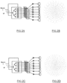
- An exemplificative block diagram of the embodiment of configuration C is shown in
Fig.2A and Fig.2B . - In the array layout shown in
Fig.2B , the element positions are used together with the element dimensions permitting to maximize the aperture filling factor and the associated aperture efficiency and directivity. - An exemplificative block diagram of the embodiment of configuration D is shown in
Fig.2C and Fig.2D . - In the array layout shown in
Fig.2D , the element positions are used together with the element dimensions with an additional constraint on the maximum element dimensions accordingly to the beam scanning requirements. The aperture filling factor and the associated aperture efficiency and directivity are optimized compatibly with the scanning requirement constraints. - The obtained improvements can be quantified in the following key figure of merit:
- 20 - 40 % reduction in number of Radiating Elements (REs) 1 Power Amplifiers (PAs),
- 1.5 - 2 dB improvement in directivity and aperture efficiency,
- A limited number of configurations has been already proposed in prior-art that make use of two [24][25][26] or three [23] different types of radiating elements placed on concentric rings but the elaborated design procedures are limited in using stochastic global optimizers (e.g. based on Genetic Algorithms) or heuristic design rules (e.g. in [23] the claimed rule is to have a sequence of at least three concentric rings of elements with the size of the elements of the second ring larger than the elements of the first and third ring). Both the approaches provide unsatisfactory results in terms of aperture efficiency and directivity loss and total number of elements to be used to populate the array aperture.
- The first step of the method of the invention is to define the desired radiative properties of the array to be designed. This is the same as in the prior art. Usually a specified Gain (G), a beamwidth (BW) and a peak sidelobe level (SLL) are indicated.
- Then, an aperture field distribution ("reference aperture") able to guarantee these radiative characteristics is identified. The reference pattern, which represents the target of the performances of the aperiodic array, may be obtained with a number of standard techniques to design continuous apertures. As an example, Taylor amplitude distribution laws for linear [27] and circular [28] apertures can be considered.
- According to the prior art, discrete sampling of the continuous aperture distribution may be directly used to realize a periodic array antenna with continuous amplitude tapering (Configuration A). Nevertheless, the direct implementation of the discrete field distribution with a specific dynamic range of the amplitude may be difficult, expensive and inefficient in terms of DC-to-RF power conversion at HPA level. In facts, especially when the requirements in terms of SLL are very stringent, the feeding distribution of the antenna aperture presents a high variability as a function of the position.
- One of the strongest motivations to introduce aperiodic arrays with equi-amplitude excited elements consists in the necessity to reduce complexity and cost of an array antenna including its beamforming network and amplification section.
- An effective solution to the problem of approximating a desired radiation pattern of a reference linear continuous taper function with an aperiodic linear array of uniformly excited omnidirectional radiating elements has been first proposed by Doyle [6] (as reported in [7]). Doyle approach consists in a weighted least-mean-square approximation of the desired radiation pattern with the array factor of the aperiodic array.
- The original Doyle's design method was first extended to different weighted least-mean-square criteria and array geometries by Toso and Angeletti in [15] and recently refined, improved and applied to circular arrays in a number of works [18]-[26].
- The first problem that we consider is that of approximating a desired radiation pattern F 0(u), generated by a linear source of continuous amplitude field i 0(x), with the radiation pattern Fa (u) of a discrete aperiodic array with amplitude field ia (x).
- In the far-field approximation, the radiation pattern of a linear continuous aperture is given by the Fourier transform of the aperture field:


- A particularly effective solution consists in exploiting a Weighted Mean Square Error (W-MSE) minimization of the difference between the reference pattern and the unknown one. The following equality, first observed by Doyle, can be demonstrated to hold true:


- To derive expression (3) we can follow Doyle reasoning evaluating the difference of the far-field radiation patterns:

- integrating by parts,

- Being e jk0Ux bounded and provided that (I0 (x)-Ia (x)) vanishes as x -> -∞ and x → ∞ , the first term nullifies and we have:

- To obtain Doyle equation (3) we now need to apply the Parseval-Plancherel theorem,

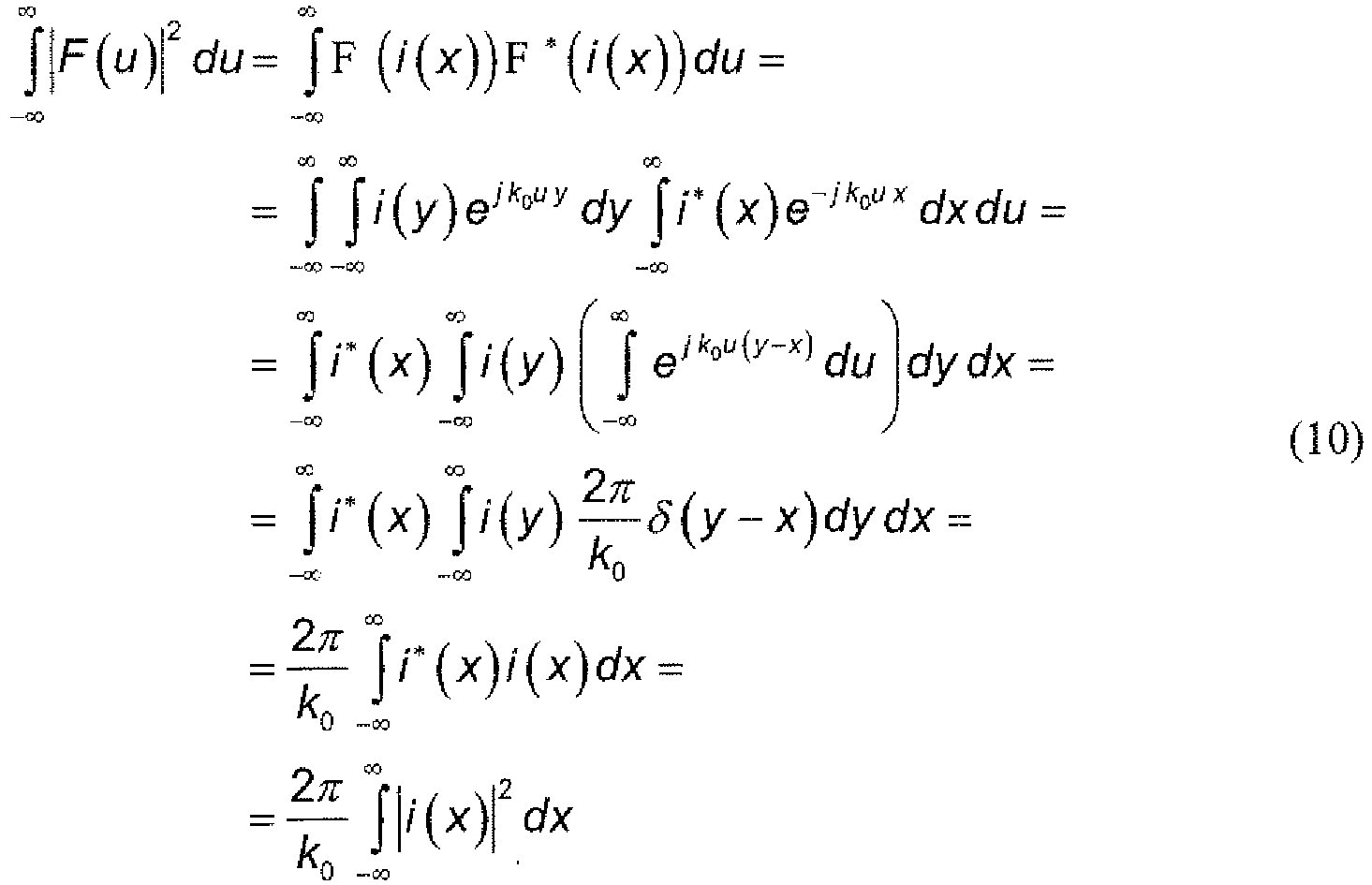
- Central to this derivation is the representation of the Dirac delta function by means of a complete set of orthogonal functions [Arfken and Weber pp.88-89] which leads to the closure equation for the continuous spectrum of plane waves [Arfken and Weber pp.90]:

- By applying the Parseval-Plancherel theorem (9) to expression (8) we obtain Doyle equality:

- The left term in Equation (12) represents a weighted mean square error (W-MSE) of the patterns with an inverse quadratic weighting function. The right term is a mean square error (MSE) of the cumulative functions of the field distributions.
- The synthesis problem is so made equivalent to the identification of an array cumulative function Ia (x) optimally fitting the reference cumulative function I 0(x).
- A solution to the problem of synthesizing a linear array of omnidirectional radiating elements with assigned number of elements N and amplitude excitations {ak ;k = 1÷N} was discussed in Angeletti and Toso [19]. The referenced work extends Doyle approach [6]-[7] which is valid for uniform excitations (i.e.
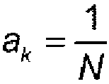
- We recall that for an array of omnidirectional radiating elements with amplitude excitations {ak ;k = 1÷N} and phase centres {xk ;k = 1÷N} we have:


- The method proposed in Angeletti and Toso [19] is based on the observation that the k-th element of the array, positioned in xk , defines an elementary cell (t k-1,tk ), with xk ∈(t k-1,tk ), such that,


- Equations (15) and (16) provide a direct mean to derive the boundaries of the elementary cells by inversion of the reference cumulative curve I 0(x):

- The element position can be then determined inverting the following equation [6][7][18]

- An alternative element position determination, based on the centroid of the field distribution function for each elementary cell, is discussed in [18] and provides similar performances.
- The solution of the linear array synthesis with omnidirectional radiating elements, often analysed from an integral point of view, offer also a differential interpretation that will allow a broader generalization.
- Under the assumption of a high number of elements, the dimensions of the elementary cells Δtk = tk - t k-1 will reduce to the limit that Δtk → 0 for N → ∞. Equation (17) can be reinterpreted as,

- This linear differential form can be considered as a particular form of the general expression,


- It is worth noting that the primitive function E(x) acts like a "grading function", i.e. the ordinate values

- In the following we will exploit this generalized differential form of the cumulative approximation condition to solve the problem of synthesizing element positions and element dimensions of aperiodic arrays with maximum efficiency radiating elements.
- It will be understood that maximum efficiency condition refers to the almost constancy, on the radiating element aperture, of the electromagnetic field generated exciting the radiating element itself.
- We now introduce the synthesis of a linear aperiodic array with linear radiating elements of maximum efficiency.
- Assuming an assigned number of elements N, and assigned power excitations {pk ;k = 1÷N} we want to determine the element positions, xk , and element aperture Δxk such that a desired radiation pattern F 0(u), generated by a linear source of continuous amplitude field i 0(x), is approximated with the radiation pattern Fa (u) of a discrete aperiodic array with amplitude field ia (x).


- For the linear elements with maximum efficiency we will assume a constant aperture field on the element aperture,


- The radiation power associated to the k-th radiation element can be determined, apart inessential impedence factors, integrating the square of the aperture field,

- In case the power of the k-th radiation element is pre-assigned, the following relationship between the aperture field amplitude and linear radiating element dimension must be respected:

- We now turn our attention to cumulative approximation condition in its differential form (20), that mutatis mutandis becomes:

- Under the additional hypothesis that the k-th radiation element has a linear dimension Δxk almost equal to its elementary cell,


- This expression can be reduced to a linear differential form in Δtk by simple manipulations,

- It can be observed that the resulting optimality condition correspond to a partitioning of the reference aperture field in elementary cells with assigned power levels,

- Nevertheless, the coincidence of the field approximation with the power approximation is strictly linked to the use of maximal efficiency linear elements and is not generally true with other elements (e.g. with omnidirectional radiating elements).
- From equation (35) it can be derived that

- The synthesis can be performed determining, in a first step, the boundaries tk of the elementary cells by inversion of the "grading function"


- In a second step the k-th element positions, xk can be determined accordingly either to a Doyle-like optimality condition (19) i.e. xk is such that,


- In a third step, the k-th element dimensions, Δxk , can be determined such to contemporarily fulfil the cumulative field distribution approximation condition,




- The aperture field amplitude coefficients bk can be derived from equation (40) using Δxk from equation (43),

- We now turn our attention to the problem of approximating a desired radiation pattern F 0(ϑ,ϕ), generated by an aperture with circular symmetric continuous amplitude field i 0(ρ), with the radiation pattern Fa (ϑ,ϕ) of a planar aperiodic array with elements disposed on circular rings of non-commensurable radius (aperiodic ring array).
- An aperture function with circular symmetry can be expressed as:

- The far field radiation pattern generated by a circular symmetric field distribution i(ρ) varying only in a radial direction ρ is given by a Hankel transform of order zero of the field distribution i(ρ):


- In the following we will use the definition of the Hankel transform of n-th order accordingly to the well-known Hankel integral formula [Watson, p. 453],


- Similarly to the linear case (6) we can evaluate the difference of the far-field radiation patterns:

- integrating by parts,


- Being J 0(k 0 uρ) bounded, and provided that (I 0(ρ)-Ia (ρ)) vanishes as ρ → 0 and ρ → ∞, the first term of (51) nullifies and we have,


- To obtain an equation similar to Doyle equation (3) we need to apply the Parseval-Plancherel theorem for Hankel transforms,


- Also in this case, the central element of the derivation is the representation of the Dirac delta function by means of a complete set of orthogonal functions [Arfken and Weber pp.88-89] which leads to the closure equation for the continuum of Bessel functions [Arfken and Weber eq. 11-59, p. 696]:

- By applying the Parseval-Plancherel theorem for hankel transforms (56) to expression (55) we obtain an equivalent Doyle equality for circular apertures:

- The left term in Equation (59) represents a weighted mean square error of the patterns with an inverse quadratic weighting function. In a symmetric way, the right term is a weighted mean square error of the radial cumulative functions of the circular field distributions.
- Similarly to the linear case, the synthesis problem is made equivalent to the identification of an approximating radial cumulative function Ia (ρ) optimally fitting the reference radial cumulative function I 0(ρ).
- We now introduce the synthesis of a stepwise radially-continuous aperture composed of a annular rings with maximum efficiency.
- Assuming an assigned number of annular rings N, and assigned power excitations per ring {pk ;k = 1÷N} we want to determine the annular ring mean radius, rk , and the annular ring radial extension Δrk such that a desired radiation pattern F 0(u), generated by a planar source with circularly symmetric continuous amplitude field i 0(ρ), is approximated with the radiation pattern Fa (u) and amplitude field ia (ρ) generated by an array of annular rings with maximum efficiency,


- Each annulus is defined by the area between two concentric circles of radii


- For an annular ring with maximum efficiency we will assume that the annular ring exhibits a constant aperture field ik (ρ) on the annulus,

- For the radiation pattern, gk (u), of the k-th annular ring with maximum efficiency, we have:


- The radiation power associated to the k-th annular ring can be determined, apart inessential impedence factors, integrating the square of the aperture field on the annulus,

- In case the power of the k-th annular ring is pre-assigned, the following relationship between the aperture field amplitude, bk , and annulus area must be respected:

- We now turn our attention to cumulative approximation condition,


ρ k is the mid radius of the elementary annulus of radial boundaries (ρ k-1,ρk ),
- We will now use the additional approximation that the k-th annular ring mid radius, rk, almost coincides with the mid radius of the elementary annulus,


- This expression is fully equivalent to equation (32), which has been derived for the case of a linear aperiodic array with maximum efficiency radiating elements.
- Under the additional hypothesis that the k-th annular ring has a radial extension Δrk almost equal to its elementary annulus,


- This expression can be reduced to a linear differential form in Δρk by simple manipulations,

- It is worth noting that, similarly to the case of a linear aperiodic array with maximum efficiency radiating elements, the resulting optimality condition correspond to a partitioning of the reference aperture field in elementary cells with assigned power levels,

- Still, the coincidence of the field approximation with the power approximation is strictly linked to the use of maximal efficiency linear elements and is not generally valid for other approximating functions.
- From equation (76) it can be derived that

- The synthesis can be performed determining, in a first step, the boundaries pk of the elementary cells by inversion of the "grading function"


- In a second step the k-th annular ring mid-radius, rk can be determined accordingly either to a Doyle-like optimality condition (19) i.e. rk is such that,


- In a third step, the k-th annular ring radial dimensions, Δrk, can be determined such to contemporarily fulfil the cumulative field distribution approximation condition,


- The amplitude coefficients bk can be derived from equation (80) using Δxk from equation (83),

- The general design procedure described in previous paragraph can be customised to different profiles of assigned power levels. An interesting profile of power level is such to have a power directly proportional to the ring diameter,


- From equation (86) it can be derived that, in this case,

- In this case, to perform the synthesis, in a first step the boundaries ρ k of the elementary cells are determined by inversion of the "grading function"


- In a second step, the annular ring mid-radius, rk can be determined accordingly to the second step described in previous paragraph.
- In a third step, the k-th annular ring radial dimensions, Δrk , are determined such to contemporarily fulfil the cumulative field distribution approximation condition (equation (80)), assigned power condition (equations (66), (67) and (85)),


- The amplitude coefficients bk can be derived from equation (80) using Δrk from equation (90),

- Finally, we are ready to tackle the problem of synthesizing an aperiodic planar arrays with maximum efficiency radiating elements arranged on concentric annular rings of incommensurable radius, element dimensions proportional to the annular ring dimensions and assigned power excitations, qk , per element of the same ring {qk;k = 1÷N}.
- In first approximation, each annular ring will exhibit a stepwise constant radial profile similar to an aperture with maximum efficiency annular-rings (refer to
Fig.9A ) so that the results already developed will be fully applicable. In the final layout the continuous annular ring will be replaced by maximum efficiency radiating elements with radial element dimensions smaller than, and preferably equal to radial width of the corresponding annulus. - According to the invention, the number of maximum efficiency radiating elements arranged on each ring is proportional to the ratio between the radius of said ring and the radial width of said maximum efficiency radiating elements.
- The invention will be described considering the case of circular radiating elements with element diameter proportional to the annular ring size (refer to
Fig.9B ), nevertheless, according to the invention, different types of maximum efficiency radiating elements can be used (e.g. with aperture corresponding to circular -Fig.31A , square, in which case the radial width correspond to the diagonal or side length -Fig.31B , annulus sector -Fig.31C , etc.). - Different technological solutions for the radiating element can used (e.g. horns, printed patches), similarly the radiating element may be constituted sub-arrays of smaller radiating elements.
- Being the power of the maximum efficiency radiating elements of k-th annular ring is pre-assigned to qk , the following relationship between the radiating element aperture field amplitude, bk , and radiating element aperture area,


- Circular radiating elements of diameter dk proportional to the annular ring radial dimensions, Δrk , allows a minimisation of the unused area between annular rings. The area of the radiating element becomes,

- With the additional hypothesis that the number of elements accommodated in each annular ring, Nk , is proportional to the ration between the annular ring circumference and the radiating element diameter (i.e. the radial width of the radiating element),


- From equation (76) it can be derived that i0 (ρ) acts as derivative of the "grading function" and

- The synthesis can be performed determining, in a first step, the boundaries ρk of the elementary cells by inversion of the "grading function"


- In a second step the k-th annular ring mid-radius, rk ,can be determined accordingly either to a Doyle-like optimality condition (19) i.e. rk is such that,


- In a third step, the k-th annular ring radial dimensions, Δrk , are determined such to fulfil the feasibility condition of non-overlapping annular rings,

- In a forth step, the number of elements per ring is defined accordingly to equation (94),

- The final fifth step consists in placing the defined integer number of elements Nk on the annular rings of mid-radius , rk. The most obvious and most accurate choice is to put them at an equal angular distance. A deterministic or random rotation of the elements from annular ring to annular ring can be also employed, although the corresponding results do not change significantly especially for large arrays.
- In case the array is designed such to have a central element, the some adaptation in the definition of the grading scale,




- In case beam scanning requirements in a Region of Interest (ROI) are applicable, an additional constraint on the maximum element dimensions, Δr max, can be imposed. The third step above must be complemented with the sub-step:

- The fourth and fifth steps described above apply without modification and fully complying with the optimality conditions in differential form as expressed by Equation (96). This is basically due to the fact that the constitutive hypothesis (94) makes Equation (96) independent on the element size but only dependent on the assigned power level per element of the k-th ring. Nevertheless it must be understood that elements diameters comparable with the elementary annuli will improve the accuracy of the approximation of the cumulative function and in turn of the radiation pattern.
- The aperture filling factor and the associated aperture efficiency and directivity are so optimized compatibly with the scanning requirement constraints.
- The described procedure has been applied, for exemplification, to the reference aperture field of
Fig.3A , with an amplitude field i 0(x) relevant to a linear Taylor amplitude distribution law [27] obtaining a desired radiation pattern F 0(u) (shown inFig.3B ) with 20 dB of side-lobe level (n bar = 3 ; SLL = -20). - Assuming equal power per element, the boundaries tk of the elementary cells are determined by inversion of the "grading function" of Equation (37) on a uniform scale (due to the equi-power hypothesis). This first step is shown in
Fig.3C . - Second step of determining the element phase center positions accordingly to the cumulative function (38) is shown in
Fig.3D . -
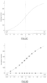
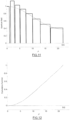
Fig.3E and Fig.3F show, respectively, the aperture fields and the cumulative functions of the linear array of maximum efficiency radiating elements (in black) and reference linear aperture (in gray). - In
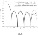
Fig.3G and Fig.3H , the aperture fields and the cumulative functions, respectively, of the linear array of maximum efficiency radiating elements (in black) and reference linear aperture (in gray) are compared with the linear array of omnidirectional radiating elements (dotted line). The resultant radiation patterns are reported inFig.3I , which indicates the goodness of the proposed synthesis solution for linear array of maximum efficiency radiating elements. - The described procedures have been applied, for exemplification, to the reference circular aperture field of
Fig.4 (radial cut) with an aperture diameter D equal to 44λ (λ being the operating wavelength of the antenna) and with an amplitude field i 0(ρ) relevant to a circular Taylor amplitude distribution law [28] obtaining a desired radiation pattern F 0(u) (shown inFig.5B ) with 25 dB of side-lobe level (n bar = 2 ; SLL = -25). -
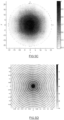
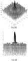
Fig.5A andFig.5C show, respectively, a three-dimensional view and a colour plot of the aperture field of the reference circular aperture. -
Fig.5D shows a colour plot of the desired radiation pattern ofFig.5 . -
Fig.5E and Fig.5F show three-dimensional views of the desired radiation pattern ofFig.5 . - An array layout according to prior-art Configuration A and relevant radiative performance are reported in
Fig.6 andFig.7A to 7F . -
Fig.6 shows how the reference circular aperture field ofFig.4 can be radially sampled (at a period of 2λ) to derive the excitations of a ring array of equal sized elements (of 2λ diameter). -
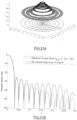
Fig.7A andFig.7C show, respectively, a three-dimensional view and a colour plot of the aperture field of the Tapered Annular Rings Array. - In
Fig.7B , azimuthal cuts of the radiation pattern of the Tapered Annular Rings Array ofFig.7A andFig.7C is compared with the desired radiation pattern ofFig.4 . -
Fig.7D shows a colour plot of the radiation pattern of the Tapered Annular Rings Array ofFig.7A andFig.7C ; andFig.7E; and Fig.7F show three-dimensional views of the pattern. - An array layout according to prior-art Configuration B and relevant radiative performance are reported in
Fig.8A to 8F . -
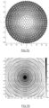
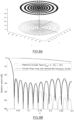
Fig.8A andFig.8C show, respectively, a three-dimensional view and a colour plot of the aperture field of the Aperiodic Array with Identical Radiating Elements disposed on concentric circular rings. - In
Fig.8B , azimuthal cuts of the radiation pattern of the Aperiodic Array with Identical Radiating Elements ofFig.8A andFig.8C is compared with the desired radiation pattern ofFig.4 . -
Fig.8D shows a colour plot of the radiation pattern of the Aperiodic Array with Identical Radiating Elements ofFig.8A andFig.8C ; andFig.8E; and Fig.8.F show three-dimensional views of the pattern. - All the following design examples refers to the preferred assumption of equal power per element.
-
Fig.10A to Fig.14F andFig.15 to Fig.18F relates to the synthesis of an array according to Configuration C, i.e. without any constraint on the maximum radiating element dimensions. -
Fig.19 to Fig.22F andFig.23 to Fig.26F relates to the synthesis of an array according to Configuration D, i.e. with a constraint on the maximum radiating element dimensions accordingly to scan requirements. - For each design example, we will report results related, first to the approximation with continuous maximum efficiency annular-rings (
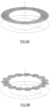
Fig.9A ), and then to the design with maximum efficiency circular radiating elements with element dimensions proportional to the annular ring size (Fig.9B ). -
Fig.10A to Fig.14F (Fig. 10A to Fig. 13B are not part of the invention) relates to the design choice of the annulus mid-radius accordingly to the Doyle-like optimality condition on the cumulative function (98). - Assuming equal power per element, the boundaries ρ k of the elementary annuli are determined by inversion of the "grading function" of Equation (97) on a uniform scale (apart the first element in case of presence of the central element). This first step is shown in
Fig.10A (not part of the invention). - Second step of determining the maximum efficiency annuli radial centers accordingly to the cumulative function (98) is shown in
Fig.10B (not part of the invention). -
Fig.11 and Fig.12 show, respectively, the aperture fields and the cumulative functions of the array of maximum efficiency annular rings (in black) and reference circular aperture (in gray) (not part of the invention). -
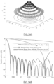
Fig.13A shows a three-dimensional view of the aperture field of the Array of Maximum Efficiency Annular-Rings (not part of the invention). - In
Fig.13B , azimuthal cuts of the radiation pattern of the Array of Maximum Efficiency Annular-Rings ofFig.13A is compared with the desired radiation pattern ofFig.4 (not part of the invention). - Substituting the with continuous maximum efficiency annular-rings (
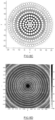
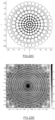
Fig.13A ) with a set of maximum efficiency circular radiating elements with element dimensions proportional to the annular ring size we obtain the aperture field ofFig.14A and the array layout ofFig.14C . - In
Fig.14B , azimuthal cuts of the radiation pattern of the Annular Ring Arrays with Maximum Efficiency Radiating Elements ofFig.14A is compared with the desired radiation pattern ofFig.4 (as well as with the radiation pattern of the Array of Maximum Efficiency Annular-Rings ofFig.13A ). -
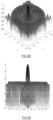
Fig.14D shows a colour plot of the radiation pattern of the array ofFig.14A andFig.14C ; andFig.14E; and Fig.14.F show three-dimensional views of the pattern. -
Fig.15 to Fig.18F (Fig. 15 to Fig. 17B are not part of the invention) relates to the design choice of the annular ring radial centre accordingly to the elementary annulus mid-radius. -
Fig.15 and Fig.16 show, respectively, the aperture fields and the cumulative functions of the circular array of maximum efficiency annular rings (in black) and reference circular aperture (in gray) (not part of the invention). -
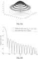
Fig.17A shows a three-dimensional view of the aperture field of the Array of Maximum Efficiency Annular-Rings (not part of the invention). - In
Fig.17B , azimuthal cuts of the radiation pattern of the Array of Maximum Efficiency Annular-Rings ofFig.17A is compared with the desired radiation pattern ofFig.4 (not part of the invention). - Substituting the continuous maximum efficiency annular-rings (
Fig.17A ) with a set of maximum efficiency circular radiating elements with element dimensions proportional to the annular ring size we obtain the aperture field ofFig.18A and the array layout ofFig.18C . - In
Fig.18B , azimuthal cuts of the radiation pattern of the Annular Ring Arrays with Maximum Efficiency Radiating Elements ofFig.18A is compared with the desired radiation pattern ofFig.4 (as well as with the radiation pattern of the Array of Maximum Efficiency Annular-Rings ofFig.17A ). -
Fig.18D shows a colour plot of the radiation pattern of the array ofFig.18A andFig.18C ; andFig.18E; and Fig.18.F show three-dimensional views of the pattern. - The following design examples refers to the additional constraint of maximum element diameter of 3.4 λ, compatible with antenna requirement of scanning of the beam over the full Earth as seen from a geostationary satellite.
-
Fig.19 to Fig.21F (Fig. 19 to Fig. 21B are not part of the invention) relates to the design choice of the annulus mid-radius accordingly to the Doyle-like optimality condition on the cumulative function (98). - The first two steps of the procedure are the same of the Example C1 (refer to
Fig.10A and Fig.10B ) (not part of the invention). - Imposing the additional constraint on the size of the annular ring we obtain, for the array of maximum efficiency annular rings, the aperture fields and the cumulative functions shown in
Fig.19 and Fig.20 , respectively (not part of the invention). -
Fig.21A shows a three-dimensional view of the aperture field of the Array of Maximum Efficiency Annular-Rings of Example D1 (not part of the invention). - In
Fig.21B , azimuthal cuts of the radiation pattern of the Array of Maximum Efficiency Annular-Rings ofFig.21A is compared with the desired radiation pattern ofFig.4 (not part of the invention). - Substituting the continuous maximum efficiency annular-rings (
Fig.21A ) with a set of maximum efficiency circular radiating elements with element dimensions proportional to the annular ring size we obtain the aperture field ofFig.21A and the array layout of Fig.21C. - In
Fig.21B , azimuthal cuts of the radiation pattern of the Annular Ring Arrays with Maximum Efficiency Radiating Elements ofFig.21A is compared with the desired radiation pattern ofFig.4 (as well as with the radiation pattern of the Array of Maximum Efficiency Annular-Rings ofFig.21A ) (not part of the invention). - Fig.21D shows a colour plot of the radiation pattern of the array of
Fig.21A and Fig.21C; and Fig.21E; and Fig.21.F show three-dimensional views of the pattern. -
Fig.23 to Fig.26F (Fig. 23 to Fig. 25B are not a part of the invention) relates to the design choice of the annulus mid-radius accordingly to the Doyle-like optimality condition on the cumulative function (98). - The first two steps of the procedure are the same of the Example C2 (refer to
Fig.10A for the first step) (not part of the invention). - Imposing the additional constraint on the size of the annular ring we obtain, for the array of maximum efficiency annular rings, the aperture fields and the cumulative functions shown in
Fig.23 and Fig.24 , respectively (not part of the invention). -
Fig.25A shows a three-dimensional view of the aperture field of the Array of Maximum Efficiency Annular-Rings of Example D2 (not part of the invention). - In
Fig.25B , azimuthal cuts of the radiation pattern of the Array of Maximum Efficiency Annular-Rings ofFig.25A is compared with the desired radiation pattern ofFig.4 (not part of the invention). - Substituting the continuous maximum efficiency annular-rings (
Fig.25A ) with a set of maximum efficiency circular radiating elements with element dimensions proportional to the annular ring size we obtain the aperture field ofFig.26A and the array layout ofFig.26C . - In
Fig.26B , azimuthal cuts of the radiation pattern of the Annular Ring Arrays with Maximum Efficiency Radiating Elements ofFig.26A is compared with the desired radiation pattern ofFig.4 (as well as with the radiation pattern of the Array of Maximum Efficiency Annular-Rings ofFig.25A ). -
Fig.26D shows a colour plot of the radiation pattern of the array ofFig.26A andFig.26C ; andFig.26E; and Fig.26.F show three-dimensional views of the pattern. - Summary table in
Fig.27 compares array configurations known in prior art (Configuration A and B) with the array configurations disclosed in the present invention declaration (Configuration C and D). - The obtained improvements can be quantified in the following key figure of merit:
- 20 - 40 % reduction in number of Radiating Elements (REs) / Power Amplifiers (PAs),
- 1.5 - 2 dB improvement in directivity and aperture efficiency.
- The achieved improvements constitute a key competitive advantage of the proposed configurations in terms both of performance and complexity reduction.
- Based on the described design methods, a preliminary design of an active array antenna has been performed.
- First, the geometry of an aperiodic and sparse front array able to radiate the required spot beam with a beam diameter of 1.75° and a side-lobe level lower than -23 dB has been synthesized. This front array includes 156 high-efficiency very-compact circular hornswith apertures ranging from 30mm to 50mm.
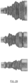
Fig.28 shows the front view of the array apertures. - Design of Maximum Efficiency radiating elements has been performed and three of the eight horns are shown in
Figure 29 . As all apertures have to be on the same plane to simplify electrical aspects, it follows that all the horns must have the same depth for mechanical reasons. -
Figure 30 shows an artistic view of the array ofFig.28 . -
-
Fig.1A illustrates the block diagram of a generic array with amplitude tapering known in prior-art (Configuration A). -
Fig.1B shows a typical layout and amplitude tapering (in gray scale) of a generic array with amplitude tapering known in prior-art (Configuration A). -
Fig.1C illustrates the block diagram of a generic Aperiodic Array with Identical Radiating Elements known in prior-art (Configuration B). -
Fig.1D shows a typical layout of a generic Aperiodic Array with Identical Radiating Elements known in prior-art (Configuration B). -
Fig.2A and Fig.2B show exemplificative block diagram and array layout, respectively, of an array accordingly to a first embodiment of the invention (Configuration C). -
Fig.2C and Fig.2D show exemplificative block diagram and array layout, respectively, of an array accordingly to a second embodiment of the invention (Configuration D). -
Fig.3A shows an exemplificative reference linear aperture field related to a linear Taylor amplitude distribution law (n bar = 3 ; SLL = -20) (not part of the invention). -
Fig.3B shows an exemplificative desired radiation pattern achievable with the reference linear aperture field ofFig.3A (not part of the invention). -
Fig.3C shows a first step of the linear design procedure consisting in determining the elementary cells by inversion of a "grading function" and a "grading scale" (not part of the invention). -
Fig.3D shows a possible second step of the linear design procedure consisting in determining the element centres accordingly to the cumulative curve (not part of the invention). -
Fig.3E and Fig.3F show, respectively, the aperture fields and the cumulative functions of the linear array of maximum efficiency radiating elements (in black) and reference linear aperture (in gray) (not part of the invention). - In
Fig.3G and Fig.3H , the aperture fields and the cumulative functions, respectively, of the linear array of maximum efficiency radiating elements (in black) and reference linear aperture (in gray) are compared with the linear array of omnidirectional radiating elements (dotted line) (not part of the invention). -
Fig.3I compares the radiation patterns of the linear array of maximum efficiency radiating elements accordingly to the described design method (in black), the reference linear aperture (in gray) and the linear array of omnidirectional radiating elements accordingly to prior art (dotted line) (not part of the invention). -
Fig.4 shows a radial cut of an exemplificative circular reference aperture relevant to a circular Taylor amplitude distribution law (n bar = 2 ; SLL = -25). -
Fig.5A shows a three-dimensional view of the aperture field of a reference circular aperture (Fig.4 ). -
Fig.5B shows an azimuthal cut of the desired radiation pattern obtained with the reference aperture field ofFig.4 andFig.5A . -
Fig.5.C shows colour plot of the aperture field of the reference circular aperture of ofFig.4 andFig.5A . -
Fig.5D shows a colour plot of the desired radiation pattern ofFig.5 . -
Fig.5E and Fig.5.F show three-dimensional views of the desired radiation pattern ofFig.5 . -
Fig.6 shows how the reference circular aperture field ofFig.4 can be radially sampled (at a period of 2λ) to derive the excitations of a ring array of equal sized elements (of 2λ diameter), according to prior art (Configuration A). -
Fig.7A shows a three-dimensional view of the aperture field of the Tapered Annular Rings Array according to prior art (Configuration A). - In
Fig.7B , azimuthal cuts of the radiation pattern of the Tapered Annular Rings Array ofFig.7A is compared with the desired radiation pattern ofFig.4 . -
Fig.7D shows a colour plot of the radiation pattern of the Tapered Annular Rings Array ofFig.7A andFig.7C . -
Fig.7E; and Fig.7F show three-dimensional views of the radiation pattern of the Tapered Annular Rings Array ofFig.7A andFig.7C . -
Fig.8A shows a three-dimensional view of the aperture field of an exemplificative Aperiodic Array with Identical Radiating Elements disposed on concentric circular rings according to prior art (Configuration B). - In
Fig.8B , azimuthal cuts of the radiation pattern of the Aperiodic Array with Identical Radiating Elements ofFig.8A is compared with the desired radiation pattern ofFig.4 . -
Fig.8C shows a colour plot view of the aperture field of an exemplificative Aperiodic Array with Identical Radiating Elements disposed on concentric circular rings according to prior art (Configuration B). -
Fig.8D shows a colour plot of the radiation pattern of the Aperiodic Array with Identical Radiating Elements ofFig.8A andFig.8C .Fig.8E; and Fig.8F show three-dimensional views of the radiation pattern of the exemplificative Aperiodic Array with Identical Radiating Elements ofFig.8A andFig.8C . -
Fig.9A shows the basic geometry of a Maximum Efficiency Annular Ring. -
Fig.9B shows how the continuous annular ring ofFig.9A can be replaced by maximum efficiency circular radiating elements with element dimensions proportional to the annular ring size. -
Fig.10A to Fig.14F (Fig. 10A to Fig. 13B are not part of the invention) relates to the synthesis of an array according to the first embodiment of the invention (Configuration C, i.e. without any constraint on the maximum radiating element dimensions) together with the design choice of the annular ring radial centre accordingly to the cumulative function optimality condition (Example C1). -
Fig.10A shows a first step of the circular design procedure consisting in determining the elementary annuli by inversion of a "grading function" and a "grading scale" (not part of the invention). -
Fig.10B shows a possible second step of the circular design procedure consisting in determining the annular rings radial centres accordingly to the cumulative curve (not part of the invention). -
Fig.11 and Fig.12 show, respectively, the aperture fields and the cumulative functions of the array of maximum efficiency annular rings (in black) and reference circular aperture (in gray) (not part of the invention). -
Fig.13A shows a three-dimensional view of the aperture field of the Array of Maximum Efficiency Annular-Rings (not part of the invention). - In
Fig.13B (not part of the invention), azimuthal cuts of the radiation pattern of the Array of Maximum Efficiency Annular-Rings ofFig.13A is compared with the desired radiation pattern ofFig.4 . -
Fig.14A shows the aperture field of an exemplificative array according to the first embodiment (Configuration C) obtained substituting the continuous maximum efficiency annular-rings ofFig.13A with a set of maximum efficiency circular radiating elements with element dimensions proportional to the annular ring size. - In
Fig.14B , azimuthal cuts of the radiation pattern of the Annular Ring Arrays with Maximum Efficiency Radiating Elements ofFig.14A is compared with the desired radiation pattern ofFig.4 (as well as with the radiation pattern of the Array of Maximum Efficiency Annular-Rings ofFig.13A ). -
Fig.14C shows the layout of an exemplificative array according to the first embodiment (Configuration C). -
Fig.14D shows a colour plot of the radiation pattern of the array ofFig.14A andFig.14C . -
Fig.14E; and Fig.14F show three-dimensional views of the pattern of the array ofFig.14A andFig.14C . -
Fig. 15 to Fig.18F (Fig. 15 to 17B are not part of the invention) relates to the synthesis of an array according to the first embodiment of the invention (Configuration C, i.e. without any constraint on the maximum radiating element dimensions) together with the design choice of annular ring radial centre accordingly to the elementary annulus mid-radius (Example C2). -
Fig.15 and Fig.16 show, respectively, the aperture fields and the cumulative functions of the circular array of maximum efficiency annular rings (in black) and reference circular aperture (in gray) (not part of the invention). -
Fig.17A shows a three-dimensional view of the aperture field of the Array of Maximum Efficiency Annular-Rings (not part of the invention). - In
Fig.17B (not part of the invention), azimuthal cuts of the radiation pattern of the Array of Maximum Efficiency Annular-Rings ofFig.17A is compared with the desired radiation pattern ofFig.4 . -
Fig.18A shows the aperture field of an exemplificative array according to the first embodiment (Configuration C) obtained substituting the continuous maximum efficiency annular-rings ofFig.17A with a set of maximum efficiency circular radiating elements with element dimensions proportional to the annular ring size. - In
Fig.18B , azimuthal cuts of the radiation pattern of the Annular Ring Arrays with Maximum Efficiency Radiating Elements ofFig.18A is compared with the desired radiation pattern ofFig.4 (as well as with the radiation pattern of the Array of Maximum Efficiency Annular-Rings ofFig.17A ). -
Fig.18C shows the layout of a second exemplificative array according to the first embodiment (Configuration D). -
Fig.18D shows a colour plot of the radiation pattern of the array ofFig.18A andFig.18C . -
Fig.18E; and Fig.18.F show three-dimensional views of the pattern of the array ofFig.18A andFig.18C . -
Fig. 19 to Fig.21F (Fig. 19 to Fig. 21B are not part of the invention) relates to the synthesis of an array according to the second embodiment of the invention (Configuration D, i.e. with the additional constraint of maximum element diameter: 3.4 λ in the example) together with the design choice of the annular ring radial centre accordingly to the cumulative function optimality condition (Example D1). -
Fig.19 and Fig.20 show, respectively, the aperture fields and the cumulative functions of the array of maximum efficiency annular rings (in black) and reference circular aperture (in gray) (not part of the invention). -
Fig.21A shows a three-dimensional view of the aperture field of the Array of Maximum Efficiency Annular-Rings (not part of the invention). - In
Fig.21B (not part of the invention), azimuthal cuts of the radiation pattern of the Array of Maximum Efficiency Annular-Rings ofFig.21A is compared with the desired radiation pattern ofFig.4 . -
Fig.22A shows the aperture field of an exemplificative array according to the second embodiment (Configuration D) obtained substituting the continuous maximum efficiency annular-rings ofFig.21A with a set of maximum efficiency circular radiating elements with element dimensions proportional to the annular ring size. - In
Fig.22B , azimuthal cuts of the radiation pattern of the Annular Ring Arrays with Maximum Efficiency Radiating Elements ofFig.22A is compared with the desired radiation pattern ofFig.4 (as well as with the radiation pattern of the Array of Maximum Efficiency Annular-Rings ofFig.21A ). -
Fig.22C shows the layout of an exemplificative array according to the second embodiment (Configuration D). -
Fig.22D shows a colour plot of the radiation pattern of the array ofFig.22A andFig.22C . -
Fig.22E; and Fig.22F show three-dimensional views of the pattern of the array ofFig.22A andFig.22C . -
Fig. 23 to Fig.26F Fig. 23 to Fig. 25B are not a part of the invention) relates to the synthesis of an array according to the second embodiment of the invention (Configuration D, i.e. with the additional constraint of maximum element diameter: 3.4 λ in the example) together with the design choice of annular ring radial centre accordingly to the elementary annulus mid-radius (Example D2). -
Fig.23 and Fig.24 show, respectively, the aperture fields and the cumulative functions of the array of maximum efficiency annular rings (in black) and reference circular aperture (in gray) (not part of the invention). -
Fig.25A shows a three-dimensional view of the aperture field of the Array of Maximum Efficiency Annular-Rings (not part of the invention). - In
Fig.25B (not part of the invention), azimuthal cuts of the radiation pattern of the Array of Maximum Efficiency Annular-Rings ofFig.25A is compared with the desired radiation pattern ofFig.4 . -
Fig.26A shows the aperture field of an exemplificative array according to the second embodiment (Configuration D) obtained substituting the continuous maximum efficiency annular-rings ofFig.25A with a set of maximum efficiency circular radiating elements with element dimensions proportional to the annular ring size. - In
Fig.26B , azimuthal cuts of the radiation pattern of the Annular Ring Arrays with Maximum Efficiency Radiating Elements ofFig.26A is compared with the desired radiation pattern ofFig.4 (as well as with the radiation pattern of the Array of Maximum Efficiency Annular-Rings ofFig.25A ). -
Fig.26C shows the layout of an exemplificative array according to the second embodiment (Configuration D). -
Fig.26D shows a colour plot of the radiation pattern of the array ofFig.26A andFig.26C . -
Fig.26E; and Fig.26F show three-dimensional views of the pattern of the array ofFig.26A andFig.26C . -
Fig.27 summarizes performances of the reported design examples. -
Fig.28 shows the front view of an array, designed accordingly to the described design methods, required to radiate spot beams with a beam diameter of 1.75° and a side-lobe level lower than -23 dB. The array includes 156 high-efficiency very-compact circular hornswith apertures ranging from 30mm to 50mm. -
Fig.29 reports the exemplificative design of three of the eight horns with Maximum Efficiency as required for the array ofFig.28 . As all apertures have to be on the same plane to simplify electrical aspects, it follows that all the horns must have the same depth for mechanical reasons. -
Figure 30 shows an exemplificative three-dimensional drawing of the array ofFig.28 and29 . -
Fig.31A to Fig.31C show exemplificative layouts of arrays designed accordingly to the present invention and employing radiating elements with different apertures (i.e. circular -Fig.31A , square -Fig.31B and annulus sector -Fig.31C ) -
- [1] R. J. Mailloux, Phased Array Antenna Handbook, 2nd Edition, Artech House, 2005, pp. 109-184
- [2] H. Unz, "Linear arrays with arbitrarily distributed elements", IRE Transactions on Antennas and Propagation, Vol. 8, pp. 222-223, Mar. 1960.
- [3] M. Skolnik, G. Nemhauser, J. Sherman III, "Dynamic programming applied to unequally spaced arrays", IEEE Transactions on Antennas and Propagation, 12, 1, pp. 35-43, 1964.
- [4] A. Ishimaru, Y.-S. Chen, "Thinning and broadbanding antenna arrays by unequal spacings", IEEE Transactions on Antennas and Propagation, 13, 1, pp. 34-42, 1965.
- [5] R. E. Willey, "Space Tapering of Linear and Planar Arrays", IRE Transactions on Antenna and Propagation, 10, pp. 369-377, 1962.
- [6] W. Doyle, "On approximating Linear Array Factors", RAND Corp Mem RM-3530-PR, February 1963.
- [7] M. I. Skolnik, ".
- [8] R. F. Harrington, "Sidelobe reduction by non-uniform element spacing," IRE Transactions on Antennas and Propagation, 9, pp. 187-192, 1961
- [9] Y. T. Lo, "A Study of Space-Tapered Arrays", IEEE Transactions on Antennas and Propagation, 14, 2, pp. 22-30, 1966.
- [10] G. Toso, M.C. Viganó, P. Angeletti, "Null-Matching for the design of linear aperiodic arrays", IEEE International Symposium on Antennas and Propagation 2007, Honolulu Hawai USA, Jun.10-15 2007.
- [11] M. Vicente-Lozano, F. Ares-Pena, E. Moreno, "Pencil-beam pattern synthesis with a uniformly excited multi-ring planar antenna," IEEE Antennas and Propagation Magazine, Vol. 42, No. 6, pp.70-74, December 2000, doi: 10.1109/74.894183
- [12]
C. H. Chen, S. S. Kuo, T. K. Wu, Density tapered transmit phased array, U.S. Patent No. US6404404 , Filed on 31 June 200 - [13] S. S. Kuo, G. P. Junker, T. K. Wu, C. H. Chen, "A density taper technique for low side lobe applications of hex array antennas", IEEE International Conference on Phased Array Systems and Technology, pp. 493-496, 2000
- [14] T. M. Milligan, "Space-tapered circular (ring) array", IEEE Antennas and Propagation Magazine, Vol. 46, No. 3, pp. 70-73, October 2004.
- [15]
G. Toso, P. Angeletti, Method of designing and manufacturing an array antenna, European patent No: EP2090995, Filed on 18 February 2008 and U.S. patent NoUS20090211079, Filed on 21 February 2008 - [16] M. C. Viganó, G. Toso, G. Caille, C. Mangenot, I E. Lager, "Sunflower Array Antenna with Adjustable Density Taper", International Journal of Antennas and Propagation, vol. 2009, Article ID 624035, 2009. doi: 10, 1155/2009/624035
- [17] P. J. Bevelacqua, C. A. Balanis, "Geometry and weight optimization for minimizing sidelobes in wideband planar arrays", IEEE Transactions on Antennas and Propagation, Vol. 57, pp.1285-1289, April. 2009.
- [18] O. M. Bucci, M. D'Urso, T. Isernia, P. Angeletti, and G. Toso, "Deterministic synthesis of uniform amplitude sparse arrays via new density taper techniques", IEEE Transactions on Antennas and Propagation, Vol. 58, No. 6, pp. 1949-1958, June 2010.
- [19] P. Angeletti, G. Toso, "Aperiodic Arrays for Space Applications: a combined Amplitude/Density Synthesis Approach", 3rd European Conference on Antennas and Propagation, EUCAP 2009, Berlin, Germany, 2009.
- [20] O. M. Bucci, T. Isernia, A. F. Morabito, S. Perna, D. Pinchera, "Aperiodic arrays for space applications: An effective strategy for the overall design", 3rd European Conference on Antennas and Propagation, EUCAP 2009, Berlin, Germany, 2009.
- [21] P. Angeletti, G. Toso, "Synthesis of Circular and Elliptical Sparse Arrays", Electronics Letters, Vol. 47, No. 5, pp. 304-305, Mar. 2011
- [22] O. M. Bucci, S. Perna, "A deterministic two dimensional density taper approach for fast design of uniform amplitude pencil beams arrays", IEEE Transactions on Antennas and Propagation, Vol. 59, No. 8, pp. 2852-2861, August 2011.
- [23]
W. N. Klimczak, Deterministic Thinned Aperture Phased Antenna Array, U.S. Patent No. US4797682, Filed on 8 June 1987 - [24] O. M. Bucci, T. Isernia, A. F. Morabito, S. Perna, and D. Pinchera, "Density and element-size tapering for the design of arrays with a reduced number of control points and high efficiency", 4th European Conference on Antennas and Propagation, EUCAP 2010, Barcelona, Spain, 2010.
- [25] O. M. Bucci, D. Pinchera, "A generalized hybrid approach for the synthesis of uniform amplitude pencil beam ring-arrays", IEEE Transactions on Antennas and Propagation, Vol. 60, No. 1, pp. 174-183, January 2012.
- [26] O. M. Bucci, S. Perna, D. Pinchera, "Advances in the deterministic synthesis of uniform amplitude pencil beam concentric ring arrays", , IEEE Transactions on Antennas and Propagation, Vol. 60, No. 7, pp. 3504-3509, July 2012.
- [27] T. T. Taylor, "Design of Line Source Antennas for Narrow Beamwidth and Low Sidelobes", IEEE Transactions on Antennas and Propagation, Vol. 3, pp. 16-28, January 1955.
- [28] T. T. Taylor, "Design of Circular Apertures for Narrow Beamwidth and Low Sidelobe", IRE Trans. on Antennas and Propagation, Vol. AP-8 pp. 17-22, 1960
- [29] G. B. Arfken, H. J. Weber, Mathematical Methods for Physicists, 6th Edition, Elsevier, San Diego, 2005). ISBN 0-12-059876-0.
- [30] E. Jahnke, F. Emde, Tables of Functions with Formulae and Curves, 4th Ed., Dover, New York, 1945
Claims (7)
- A method of manufacturing an array antenna comprising:- a design phase, comprising synthesizing an array layout of said array antenna and choosing or designing radiating elements to be arranged according to said array layout, the design phase comprising the steps of:a. defining a continuous reference aperture;b. subdividing said continuous reference aperture into a plurality of elementary cells with assigned power levels;c. determining, within each elementary cell, a position for the radiating elements, said radiating elements having a field amplitude which is substantially uniform over their whole aperture;d. determining a size and an aperture field amplitude of each radiating element, such that a variation of a cumulative field distribution of the resulting array antenna aperture over each elementary cell is substantially equal to a variation of a cumulative field distribution of said reference aperture over the same elementary cells, subject to size constraints,- a phase of physically making said array antenna, comprising arranging said radiating elements according to said array layout, said array antenna is an aperiodic planar array antenna constituted by concentric annular rings of incommensurable radius and a plurality of radiating elements arranged with each annular ring, the number of radiating elements arranged on each annular ring being proportional to the ratio between the radius of said annular ring and the radial width of said radiating elements, and the radial width of the radiating elements arranged on each annular ring being proportional to the radial width of said annular ring, the radiating elements of the same annular ring having the same assigned power excitations.
- A method according to claim 1, wherein:- each said elementary cell, identified by index "k", is constituted by a concentric annulus comprised between an inner radius ρ k-1 and an outer radius ρk ;- said cumulative field distributions are defined as

- A method according to claim 2, comprising arranging, within each said annulus, a plurality of radiating elements having a same area and a same excitation power level and whose centres are arranged on a ring concentric with said annulus, wherein said step c. comprises determining the radius of each said ring.
- A method according to claim 3, wherein said step c. comprises determining the radius rk of each said ring so that it coincides with the mean radius of the corresponding annulus.
- A method according to any of claims 3 or 4, wherein said radiating elements are chosen to have a radial width smaller than or equal to the radial width of the corresponding annulus.
- A method according to any of claims 3 to 5, comprising determining an upper limit for said radial width of said radiating elements on the basis of beam coverage requirements.
- A method according to any of claims 4 to 6, further comprising arranging a radiating element at the centre of the antenna.
Applications Claiming Priority (2)
| Application Number | Priority Date | Filing Date | Title |
|---|---|---|---|
| IB2013000675 | 2013-01-24 | ||
| PCT/IB2013/058050 WO2014114993A1 (en) | 2013-01-24 | 2013-08-28 | Array antenna with optimized elements positions and dimensions |
Publications (3)
| Publication Number | Publication Date |
|---|---|
| EP2949002A1 EP2949002A1 (en) | 2015-12-02 |
| EP2949002B1 true EP2949002B1 (en) | 2023-10-11 |
| EP2949002C0 EP2949002C0 (en) | 2023-10-11 |
Family
ID=49515428
Family Applications (1)
| Application Number | Title | Priority Date | Filing Date |
|---|---|---|---|
| EP13785632.4A Active EP2949002B1 (en) | 2013-01-24 | 2013-08-28 | Array antenna with optimized elements positions and dimensions |
Country Status (3)
| Country | Link |
|---|---|
| US (1) | US10431900B2 (en) |
| EP (1) | EP2949002B1 (en) |
| WO (1) | WO2014114993A1 (en) |
Families Citing this family (12)
| Publication number | Priority date | Publication date | Assignee | Title |
|---|---|---|---|---|
| DE102014106060A1 (en) * | 2014-04-30 | 2015-11-19 | Karlsruher Institut für Technologie | antenna array |
| CN105356068B (en) * | 2015-10-12 | 2018-01-30 | 中国电子科技集团公司第五十四研究所 | A kind of Optimization Design of broadband feed |
| CN105337045B (en) * | 2015-10-12 | 2018-01-30 | 中国电子科技集团公司第五十四研究所 | A kind of method for optimizing of reflector antenna Aperture field distribution |
| CN107275806B (en) * | 2017-05-19 | 2019-11-12 | 北京空间飞行器总体设计部 | A Weighting Method for Phased Array Antenna |
| US11705632B2 (en) * | 2017-09-22 | 2023-07-18 | Duke University | Symphotic structures |
| EP3791442A4 (en) * | 2018-05-11 | 2022-02-09 | Quintel Cayman Limited | MULTIBAND CELLULAR ANTENNA SYSTEM |
| US10784575B2 (en) * | 2018-07-18 | 2020-09-22 | The Boeing Company | Phased antenna array and method of thinning thereof |
| CN109687158B (en) * | 2018-12-27 | 2020-04-21 | 北京理工大学 | All-media multi-beam scanning Lunbo lens structure and printing method suitable for 3D printing |
| EP3690483B1 (en) | 2019-02-04 | 2023-05-03 | Fraunhofer-Gesellschaft zur Förderung der angewandten Forschung e.V. | A method for synthesis of antenna array layouts or selection of waveform in a set of mutually incoherent apertures for radar and radio-frequency applications |
| CN110879924A (en) * | 2019-12-09 | 2020-03-13 | 西安电子工程研究所 | A Modeling and Simulation Method of Digital Phased Array Antenna |
| CN115986404A (en) * | 2022-12-30 | 2023-04-18 | 中国电子科技集团公司第五十四研究所 | A Beam Scanning and Antenna Position Selection Method for Wideband MIMO Radar |
| EP4492114B1 (en) * | 2023-07-11 | 2025-08-06 | Tata Consultancy Services Limited | Optically sparse primary aperture for high spatial resolution imaging |
Family Cites Families (8)
| Publication number | Priority date | Publication date | Assignee | Title |
|---|---|---|---|---|
| US4797682A (en) | 1987-06-08 | 1989-01-10 | Hughes Aircraft Company | Deterministic thinned aperture phased antenna array |
| US6404404B1 (en) * | 2000-07-31 | 2002-06-11 | Trw Inc. | Density tapered transmit phased array |
| ATE522951T1 (en) * | 2006-05-24 | 2011-09-15 | Wavebender Inc | INTEGRATED WAVEGUIDE ANTENNA AND ARRAY |
| US7656359B2 (en) * | 2006-05-24 | 2010-02-02 | Wavebender, Inc. | Apparatus and method for antenna RF feed |
| US7554505B2 (en) * | 2006-05-24 | 2009-06-30 | Wavebender, Inc. | Integrated waveguide antenna array |
| EP2090995A1 (en) | 2008-02-18 | 2009-08-19 | Agence Spatiale Europeenne | A method of designing and manufacturing an array antenna |
| US7797816B2 (en) | 2008-02-21 | 2010-09-21 | Agence Spatiale Europeenne | Method of designing and manufacturing an array antenna |
| EP2697865B1 (en) * | 2011-04-12 | 2019-02-13 | Agence Spatiale Européenne | Array antenna having a radiation pattern with a controlled envelope, and method of manufacturing it |
-
2013
- 2013-08-28 EP EP13785632.4A patent/EP2949002B1/en active Active
- 2013-08-28 US US14/761,162 patent/US10431900B2/en active Active
- 2013-08-28 WO PCT/IB2013/058050 patent/WO2014114993A1/en not_active Ceased
Also Published As
| Publication number | Publication date |
|---|---|
| EP2949002C0 (en) | 2023-10-11 |
| US20150333412A1 (en) | 2015-11-19 |
| US10431900B2 (en) | 2019-10-01 |
| EP2949002A1 (en) | 2015-12-02 |
| WO2014114993A1 (en) | 2014-07-31 |
Similar Documents
| Publication | Publication Date | Title |
|---|---|---|
| US10431900B2 (en) | Array antenna with optimized elements positions and dimensions | |
| EP3783738B1 (en) | Wideband beam broadening for phased array antenna systems | |
| Angeletti et al. | Array antennas with jointly optimized elements positions and dimensions part II: Planar circular arrays | |
| EP2697865B1 (en) | Array antenna having a radiation pattern with a controlled envelope, and method of manufacturing it | |
| EP3278398B1 (en) | Sparse phase-mode planar feed for circular arrays | |
| Angeletti et al. | Array antennas with jointly optimized elements positions and dimensions part I: Linear arrays | |
| US7797816B2 (en) | Method of designing and manufacturing an array antenna | |
| CN108631046A (en) | A kind of quasi-plane wave generator and generation method based on array antenna | |
| CN109830814B (en) | Annular thin cloth antenna array design method and annular thin cloth antenna array | |
| Afsari et al. | Adaptive beamforming by compact arrays using evolutionary optimization of Schelkunoff polynomials | |
| US11502418B2 (en) | Network for forming multiple beams from a planar array | |
| Pal et al. | Quad-element MIMO antenna with diverse radiation pattern characteristics and enhanced gain for 5.9 GHz V2X communications | |
| Laffey et al. | 1λ spaced dual radiating modes based phased array antenna using silicon RFICs with grating lobe cancellation | |
| Zeng et al. | A general analytical arrangement for large-spacing planar scanning array grating lobe suppression based on energy homogenization theory | |
| Kehn et al. | Definition of unifying decoupling efficiency of different array antennas—Case study of dense focal plane array feed for parabolic reflector | |
| Mirmozafari et al. | A compact wideband multi-beam antenna for VHF/UHF directional networking applications | |
| Bui et al. | Dual-polarized multi-mode hemispherical beam-scanning and null-steering antenna | |
| US9634401B2 (en) | Antenna array | |
| Rupcic et al. | Reduction of sidelobes by nonuniform elements spacing of a spherical antenna array | |
| Ivashina et al. | Efficiency analysis of focal plane arrays in deep dishes | |
| Dubovitskiy | Practical design considerations for sparse antenna array using reflector antenna with continuously adjustable phase center displacement | |
| Aljaf et al. | Multiple antenna array patterns reconfiguration with common excitation amplitudes and optimized phases | |
| Arif et al. | Multibeam metasurface antenna based on a single substrate layer and one feeding port for millimetre wave applications | |
| Suárez et al. | Experimental validation of linear aperiodic array for grating lobe suppression | |
| Zuniga et al. | Effect of a central antenna element on the directivity, half-power beamwidth and side-lobe level of circular antenna arrays |
Legal Events
| Date | Code | Title | Description |
|---|---|---|---|
| PUAI | Public reference made under article 153(3) epc to a published international application that has entered the european phase |
Free format text: ORIGINAL CODE: 0009012 |
|
| 17P | Request for examination filed |
Effective date: 20150805 |
|
| AK | Designated contracting states |
Kind code of ref document: A1 Designated state(s): AL AT BE BG CH CY CZ DE DK EE ES FI FR GB GR HR HU IE IS IT LI LT LU LV MC MK MT NL NO PL PT RO RS SE SI SK SM TR |
|
| AX | Request for extension of the european patent |
Extension state: BA ME |
|
| DAX | Request for extension of the european patent (deleted) | ||
| STAA | Information on the status of an ep patent application or granted ep patent |
Free format text: STATUS: EXAMINATION IS IN PROGRESS |
|
| 17Q | First examination report despatched |
Effective date: 20180104 |
|
| GRAP | Despatch of communication of intention to grant a patent |
Free format text: ORIGINAL CODE: EPIDOSNIGR1 |
|
| STAA | Information on the status of an ep patent application or granted ep patent |
Free format text: STATUS: GRANT OF PATENT IS INTENDED |
|
| RIC1 | Information provided on ipc code assigned before grant |
Ipc: H01Q 21/22 20060101ALI20230428BHEP Ipc: H01Q 21/20 20060101AFI20230428BHEP |
|
| INTG | Intention to grant announced |
Effective date: 20230524 |
|
| GRAS | Grant fee paid |
Free format text: ORIGINAL CODE: EPIDOSNIGR3 |
|
| GRAA | (expected) grant |
Free format text: ORIGINAL CODE: 0009210 |
|
| STAA | Information on the status of an ep patent application or granted ep patent |
Free format text: STATUS: THE PATENT HAS BEEN GRANTED |
|
| AK | Designated contracting states |
Kind code of ref document: B1 Designated state(s): AL AT BE BG CH CY CZ DE DK EE ES FI FR GB GR HR HU IE IS IT LI LT LU LV MC MK MT NL NO PL PT RO RS SE SI SK SM TR |
|
| REG | Reference to a national code |
Ref country code: GB Ref legal event code: FG4D |
|
| REG | Reference to a national code |
Ref country code: CH Ref legal event code: EP |
|
| REG | Reference to a national code |
Ref country code: DE Ref legal event code: R096 Ref document number: 602013084784 Country of ref document: DE |
|
| REG | Reference to a national code |
Ref country code: IE Ref legal event code: FG4D |
|
| U01 | Request for unitary effect filed |
Effective date: 20231109 |
|
| U07 | Unitary effect registered |
Designated state(s): AT BE BG DE DK EE FI FR IT LT LU LV MT NL PT SE SI Effective date: 20231115 |
|
| PG25 | Lapsed in a contracting state [announced via postgrant information from national office to epo] |
Ref country code: GR Free format text: LAPSE BECAUSE OF FAILURE TO SUBMIT A TRANSLATION OF THE DESCRIPTION OR TO PAY THE FEE WITHIN THE PRESCRIBED TIME-LIMIT Effective date: 20240112 |
|
| PG25 | Lapsed in a contracting state [announced via postgrant information from national office to epo] |
Ref country code: IS Free format text: LAPSE BECAUSE OF FAILURE TO SUBMIT A TRANSLATION OF THE DESCRIPTION OR TO PAY THE FEE WITHIN THE PRESCRIBED TIME-LIMIT Effective date: 20240211 |
|
| PG25 | Lapsed in a contracting state [announced via postgrant information from national office to epo] |
Ref country code: ES Free format text: LAPSE BECAUSE OF FAILURE TO SUBMIT A TRANSLATION OF THE DESCRIPTION OR TO PAY THE FEE WITHIN THE PRESCRIBED TIME-LIMIT Effective date: 20231011 |
|
| PG25 | Lapsed in a contracting state [announced via postgrant information from national office to epo] |
Ref country code: IS Free format text: LAPSE BECAUSE OF FAILURE TO SUBMIT A TRANSLATION OF THE DESCRIPTION OR TO PAY THE FEE WITHIN THE PRESCRIBED TIME-LIMIT Effective date: 20240211 Ref country code: GR Free format text: LAPSE BECAUSE OF FAILURE TO SUBMIT A TRANSLATION OF THE DESCRIPTION OR TO PAY THE FEE WITHIN THE PRESCRIBED TIME-LIMIT Effective date: 20240112 Ref country code: ES Free format text: LAPSE BECAUSE OF FAILURE TO SUBMIT A TRANSLATION OF THE DESCRIPTION OR TO PAY THE FEE WITHIN THE PRESCRIBED TIME-LIMIT Effective date: 20231011 |
|
| PG25 | Lapsed in a contracting state [announced via postgrant information from national office to epo] |
Ref country code: RS Free format text: LAPSE BECAUSE OF FAILURE TO SUBMIT A TRANSLATION OF THE DESCRIPTION OR TO PAY THE FEE WITHIN THE PRESCRIBED TIME-LIMIT Effective date: 20231011 Ref country code: PL Free format text: LAPSE BECAUSE OF FAILURE TO SUBMIT A TRANSLATION OF THE DESCRIPTION OR TO PAY THE FEE WITHIN THE PRESCRIBED TIME-LIMIT Effective date: 20231011 Ref country code: NO Free format text: LAPSE BECAUSE OF FAILURE TO SUBMIT A TRANSLATION OF THE DESCRIPTION OR TO PAY THE FEE WITHIN THE PRESCRIBED TIME-LIMIT Effective date: 20240111 Ref country code: HR Free format text: LAPSE BECAUSE OF FAILURE TO SUBMIT A TRANSLATION OF THE DESCRIPTION OR TO PAY THE FEE WITHIN THE PRESCRIBED TIME-LIMIT Effective date: 20231011 |
|
| REG | Reference to a national code |
Ref country code: DE Ref legal event code: R097 Ref document number: 602013084784 Country of ref document: DE |
|
| PG25 | Lapsed in a contracting state [announced via postgrant information from national office to epo] |
Ref country code: CZ Free format text: LAPSE BECAUSE OF FAILURE TO SUBMIT A TRANSLATION OF THE DESCRIPTION OR TO PAY THE FEE WITHIN THE PRESCRIBED TIME-LIMIT Effective date: 20231011 |
|
| PG25 | Lapsed in a contracting state [announced via postgrant information from national office to epo] |
Ref country code: SK Free format text: LAPSE BECAUSE OF FAILURE TO SUBMIT A TRANSLATION OF THE DESCRIPTION OR TO PAY THE FEE WITHIN THE PRESCRIBED TIME-LIMIT Effective date: 20231011 |
|
| PG25 | Lapsed in a contracting state [announced via postgrant information from national office to epo] |
Ref country code: SM Free format text: LAPSE BECAUSE OF FAILURE TO SUBMIT A TRANSLATION OF THE DESCRIPTION OR TO PAY THE FEE WITHIN THE PRESCRIBED TIME-LIMIT Effective date: 20231011 Ref country code: SK Free format text: LAPSE BECAUSE OF FAILURE TO SUBMIT A TRANSLATION OF THE DESCRIPTION OR TO PAY THE FEE WITHIN THE PRESCRIBED TIME-LIMIT Effective date: 20231011 Ref country code: RO Free format text: LAPSE BECAUSE OF FAILURE TO SUBMIT A TRANSLATION OF THE DESCRIPTION OR TO PAY THE FEE WITHIN THE PRESCRIBED TIME-LIMIT Effective date: 20231011 Ref country code: CZ Free format text: LAPSE BECAUSE OF FAILURE TO SUBMIT A TRANSLATION OF THE DESCRIPTION OR TO PAY THE FEE WITHIN THE PRESCRIBED TIME-LIMIT Effective date: 20231011 |
|
| PLBE | No opposition filed within time limit |
Free format text: ORIGINAL CODE: 0009261 |
|
| STAA | Information on the status of an ep patent application or granted ep patent |
Free format text: STATUS: NO OPPOSITION FILED WITHIN TIME LIMIT |
|
| 26N | No opposition filed |
Effective date: 20240712 |
|
| U20 | Renewal fee for the european patent with unitary effect paid |
Year of fee payment: 12 Effective date: 20240827 |
|
| PG25 | Lapsed in a contracting state [announced via postgrant information from national office to epo] |
Ref country code: MC Free format text: LAPSE BECAUSE OF FAILURE TO SUBMIT A TRANSLATION OF THE DESCRIPTION OR TO PAY THE FEE WITHIN THE PRESCRIBED TIME-LIMIT Effective date: 20231011 |
|
| PG25 | Lapsed in a contracting state [announced via postgrant information from national office to epo] |
Ref country code: IE Free format text: LAPSE BECAUSE OF NON-PAYMENT OF DUE FEES Effective date: 20240828 |
|
| U20 | Renewal fee for the european patent with unitary effect paid |
Year of fee payment: 13 Effective date: 20250827 |
|
| PGFP | Annual fee paid to national office [announced via postgrant information from national office to epo] |
Ref country code: GB Payment date: 20250821 Year of fee payment: 13 |
|
| PGFP | Annual fee paid to national office [announced via postgrant information from national office to epo] |
Ref country code: CH Payment date: 20250901 Year of fee payment: 13 |
|
| PG25 | Lapsed in a contracting state [announced via postgrant information from national office to epo] |
Ref country code: CY Free format text: LAPSE BECAUSE OF FAILURE TO SUBMIT A TRANSLATION OF THE DESCRIPTION OR TO PAY THE FEE WITHIN THE PRESCRIBED TIME-LIMIT; INVALID AB INITIO Effective date: 20130828 |
|
| PG25 | Lapsed in a contracting state [announced via postgrant information from national office to epo] |
Ref country code: HU Free format text: LAPSE BECAUSE OF FAILURE TO SUBMIT A TRANSLATION OF THE DESCRIPTION OR TO PAY THE FEE WITHIN THE PRESCRIBED TIME-LIMIT; INVALID AB INITIO Effective date: 20130828 |