EP2947752A1 - Wedge mechanism - Google Patents
Wedge mechanism Download PDFInfo
- Publication number
- EP2947752A1 EP2947752A1 EP14382175.9A EP14382175A EP2947752A1 EP 2947752 A1 EP2947752 A1 EP 2947752A1 EP 14382175 A EP14382175 A EP 14382175A EP 2947752 A1 EP2947752 A1 EP 2947752A1
- Authority
- EP
- European Patent Office
- Prior art keywords
- assembly
- wedge
- guide member
- wind turbine
- wedge element
- Prior art date
- Legal status (The legal status is an assumption and is not a legal conclusion. Google has not performed a legal analysis and makes no representation as to the accuracy of the status listed.)
- Withdrawn
Links
- 230000007246 mechanism Effects 0.000 title claims abstract description 50
- 230000000712 assembly Effects 0.000 claims abstract description 13
- 238000000429 assembly Methods 0.000 claims abstract description 13
- 238000006073 displacement reaction Methods 0.000 claims description 3
- 238000012423 maintenance Methods 0.000 description 5
- 238000003466 welding Methods 0.000 description 5
- 230000008439 repair process Effects 0.000 description 4
- 230000008901 benefit Effects 0.000 description 2
- 238000004026 adhesive bonding Methods 0.000 description 1
- 238000006243 chemical reaction Methods 0.000 description 1
- 230000005284 excitation Effects 0.000 description 1
- 238000001125 extrusion Methods 0.000 description 1
- 239000003292 glue Substances 0.000 description 1
- 238000002844 melting Methods 0.000 description 1
- 230000008018 melting Effects 0.000 description 1
- 238000000034 method Methods 0.000 description 1
- 238000012986 modification Methods 0.000 description 1
- 230000004048 modification Effects 0.000 description 1
- 238000003825 pressing Methods 0.000 description 1
- 230000008569 process Effects 0.000 description 1
- 238000009877 rendering Methods 0.000 description 1
- 238000007669 thermal treatment Methods 0.000 description 1
Images


Classifications
-
- H—ELECTRICITY
- H02—GENERATION; CONVERSION OR DISTRIBUTION OF ELECTRIC POWER
- H02K—DYNAMO-ELECTRIC MACHINES
- H02K1/00—Details of the magnetic circuit
- H02K1/06—Details of the magnetic circuit characterised by the shape, form or construction
- H02K1/22—Rotating parts of the magnetic circuit
- H02K1/28—Means for mounting or fastening rotating magnetic parts on to, or to, the rotor structures
-
- H—ELECTRICITY
- H02—GENERATION; CONVERSION OR DISTRIBUTION OF ELECTRIC POWER
- H02K—DYNAMO-ELECTRIC MACHINES
- H02K1/00—Details of the magnetic circuit
- H02K1/06—Details of the magnetic circuit characterised by the shape, form or construction
- H02K1/22—Rotating parts of the magnetic circuit
- H02K1/27—Rotor cores with permanent magnets
- H02K1/2706—Inner rotors
- H02K1/272—Inner rotors the magnetisation axis of the magnets being perpendicular to the rotor axis
- H02K1/274—Inner rotors the magnetisation axis of the magnets being perpendicular to the rotor axis the rotor consisting of two or more circumferentially positioned magnets
- H02K1/2753—Inner rotors the magnetisation axis of the magnets being perpendicular to the rotor axis the rotor consisting of two or more circumferentially positioned magnets the rotor consisting of magnets or groups of magnets arranged with alternating polarity
- H02K1/278—Surface mounted magnets; Inset magnets
-
- F—MECHANICAL ENGINEERING; LIGHTING; HEATING; WEAPONS; BLASTING
- F03—MACHINES OR ENGINES FOR LIQUIDS; WIND, SPRING, OR WEIGHT MOTORS; PRODUCING MECHANICAL POWER OR A REACTIVE PROPULSIVE THRUST, NOT OTHERWISE PROVIDED FOR
- F03D—WIND MOTORS
- F03D9/00—Adaptations of wind motors for special use; Combinations of wind motors with apparatus driven thereby; Wind motors specially adapted for installation in particular locations
- F03D9/20—Wind motors characterised by the driven apparatus
- F03D9/25—Wind motors characterised by the driven apparatus the apparatus being an electrical generator
-
- F—MECHANICAL ENGINEERING; LIGHTING; HEATING; WEAPONS; BLASTING
- F16—ENGINEERING ELEMENTS AND UNITS; GENERAL MEASURES FOR PRODUCING AND MAINTAINING EFFECTIVE FUNCTIONING OF MACHINES OR INSTALLATIONS; THERMAL INSULATION IN GENERAL
- F16B—DEVICES FOR FASTENING OR SECURING CONSTRUCTIONAL ELEMENTS OR MACHINE PARTS TOGETHER, e.g. NAILS, BOLTS, CIRCLIPS, CLAMPS, CLIPS OR WEDGES; JOINTS OR JOINTING
- F16B2/00—Friction-grip releasable fastenings
-
- H—ELECTRICITY
- H02—GENERATION; CONVERSION OR DISTRIBUTION OF ELECTRIC POWER
- H02K—DYNAMO-ELECTRIC MACHINES
- H02K1/00—Details of the magnetic circuit
- H02K1/06—Details of the magnetic circuit characterised by the shape, form or construction
- H02K1/22—Rotating parts of the magnetic circuit
- H02K1/27—Rotor cores with permanent magnets
-
- H—ELECTRICITY
- H02—GENERATION; CONVERSION OR DISTRIBUTION OF ELECTRIC POWER
- H02K—DYNAMO-ELECTRIC MACHINES
- H02K15/00—Processes or apparatus specially adapted for manufacturing, assembling, maintaining or repairing of dynamo-electric machines
- H02K15/02—Processes or apparatus specially adapted for manufacturing, assembling, maintaining or repairing of dynamo-electric machines of stator or rotor bodies
- H02K15/03—Processes or apparatus specially adapted for manufacturing, assembling, maintaining or repairing of dynamo-electric machines of stator or rotor bodies having permanent magnets
-
- H—ELECTRICITY
- H02—GENERATION; CONVERSION OR DISTRIBUTION OF ELECTRIC POWER
- H02K—DYNAMO-ELECTRIC MACHINES
- H02K15/00—Processes or apparatus specially adapted for manufacturing, assembling, maintaining or repairing of dynamo-electric machines
- H02K15/50—Disassembling, repairing or modifying dynamo-electric machines
-
- H—ELECTRICITY
- H02—GENERATION; CONVERSION OR DISTRIBUTION OF ELECTRIC POWER
- H02K—DYNAMO-ELECTRIC MACHINES
- H02K7/00—Arrangements for handling mechanical energy structurally associated with dynamo-electric machines, e.g. structural association with mechanical driving motors or auxiliary dynamo-electric machines
- H02K7/18—Structural association of electric generators with mechanical driving motors, e.g. with turbines
- H02K7/1807—Rotary generators
- H02K7/1823—Rotary generators structurally associated with turbines or similar engines
- H02K7/183—Rotary generators structurally associated with turbines or similar engines wherein the turbine is a wind turbine
- H02K7/1838—Generators mounted in a nacelle or similar structure of a horizontal axis wind turbine
-
- Y—GENERAL TAGGING OF NEW TECHNOLOGICAL DEVELOPMENTS; GENERAL TAGGING OF CROSS-SECTIONAL TECHNOLOGIES SPANNING OVER SEVERAL SECTIONS OF THE IPC; TECHNICAL SUBJECTS COVERED BY FORMER USPC CROSS-REFERENCE ART COLLECTIONS [XRACs] AND DIGESTS
- Y02—TECHNOLOGIES OR APPLICATIONS FOR MITIGATION OR ADAPTATION AGAINST CLIMATE CHANGE
- Y02E—REDUCTION OF GREENHOUSE GAS [GHG] EMISSIONS, RELATED TO ENERGY GENERATION, TRANSMISSION OR DISTRIBUTION
- Y02E10/00—Energy generation through renewable energy sources
- Y02E10/70—Wind energy
- Y02E10/72—Wind turbines with rotation axis in wind direction
Definitions
- the present disclosure relates to mechanisms for attaching two or more assemblies to each other, in particular in wind turbine applications.
- the attachment of a magnet module to the rotor may be carried out in different ways.
- the magnet module may be for example attached to the rotor directly, such as by welding, through bolted connections.
- the magnet module or even the magnets themselves may be attached to the rotor glued to a rotor body, by stamping the ends of the magnets to hold them in place, attached through the use of clamps coupled to the rotor body or directly to the rotor rim, etc.
- a further disadvantage is that a large number of bolts are used.
- in attachment by gluing reliability is reduced as it is difficult to ensure attachment of the assemblies over time.
- the magnets are inserted longitudinally into guide means.
- the guide means comprise wedge shaped guide grooves that are formed in the rotor.
- the guide grooves are adapted for receiving the magnets such that they are distributed at the periphery of the rotor and fastened therein.
- a medium that hardens by a chemical reaction and/or thermal treatment is provided. Such medium is intended for ensuring the attachment of the magnets in the grooves filling the gaps existing therebetween.
- Document EP2523316 filed by the present applicant discloses a generator rotor having a rotor rim upon which a plurality of permanent magnet modules is arranged extending in an axial direction of the generator rotor.
- T-shaped anchors are fitted in corresponding grooves that are formed in the wind turbine rotor.
- Such anchors are provided with bores suitable for accommodating bolts for fixing the anchor to the rotor rim.
- the permanent magnet modules are inserted between two neighbouring anchors and fixed in place by means of bolts.
- the present mechanism for attaching two assemblies to each other in wind turbine applications has been developed in order to overcome or at least mitigate the above disclosed disadvantages related to prior art solutions. It has been also found that the present mechanism provides a number of additional advantages as it will be disclosed hereinbelow.
- a mechanism for attaching at least a first assembly and a second assembly in wind turbine applications is provided.
- the first assembly comprises a number of sectors.
- a sector means an area, portion or region of the assembly.
- the first assembly may be, for example, rotor active parts such as a wind turbine magnet module assembly.
- a magnet module sector is an area, portion or region of the magnet module.
- the second assembly may be a wind turbine rotor, and specifically a wind turbine rotor rim.
- Other examples are not ruled out such as those in which the first assembly is a wind turbine stator active part portion and the second assembly is a wind turbine stator structure such a stator housing.
- the stator active part portion is formed by stator teeth around which a coil is provided.
- the present mechanism is referred herein to as wedge mechanism as it comprises at least one wedge element.
- a wedge element as used herein is a piece or block having at least one inclined plane.
- the present mechanism further comprises a guide member that is attached to the second assembly.
- the guide member is adapted for receiving the above mentioned wedge element.
- At least an inactive position of the mechanism and an active position of the mechanism are defined.
- the first assembly and the second assembly can be detached from each other, for example for maintenance and repair operations.
- the active position of the mechanism at least one of the wedge element and the guide member presses against two different sectors, that is, areas, portions or regions, of the first assembly. The first assembly and the second assembly remain attached to each other ready for operation.
- the magnet module assembly may comprise a number of magnet modules.
- the wedge parts of the wedge element, in use act on sectors of different magnet modules.
- the wedge element, in use act on different sectors of the same magnet module.
- the wedge element of the mechanism may comprise at least two wedge parts and the guide member is adapted for slidingly receiving the wedge parts.
- a relative axial displacement of said wedge parts along the guide member causes the wedge parts to press against two different sectors of the first assembly.
- the force applied to respective opposite narrow ends of different, adjacent wedge parts is converted into forces perpendicular to the respective inclined surfaces of said wedge parts. This results in that the outer surfaces of the wedge parts press against the opposite sectors of the first assembly such that the first assembly and the second assembly are maintained attached to each other.
- the guide member may comprise at least two guide portions.
- the guide portions of the guide member are adapted for receiving at least one wedge element therebetween. As the wedge element is fitted between the guide portions of the guide member, said guide portions are forced to open outwards towards different sectors of the first assembly. This results in that the first assembly and the second assembly are maintained attached to each other.
- the guide portions may be adapted to open outwards towards different sectors of the first assembly when the wedge element is fitted axially therebetween. Still in the above example, the guide portions of the guide member may be adapted to open outwards towards different sectors of the first assembly when the wedge element is fitted radially therebetween.
- the wedge element may comprise at least two wedge parts.
- the present mechanism provides an improved feasibility of assembly and fastening operations of the generator active parts such as rotor magnet modules, stator core, etc.
- a generator comprising a stator, a rotor and a number of permanent magnets is also disclosed herein.
- the generator further comprises the wedge mechanism described above for attaching the magnets to the rotor.
- a wind turbine comprising the above generator having said wedge mechanism for attaching the magnets to the rotor, for attaching stator active part portion to a stator structure, etc.
- the drawings show two non-limiting examples of the present wedge mechanism 10.
- the mechanism 10 shown is intended for attaching a wind turbine magnet module assembly 20, that is, a whole series of magnet modules, to a wind turbine rotor rim 30.
- the magnet module assembly 20 comprises a number of sectors 21, 22, only two of which have been shown in the drawings for simplicity. Sectors 21, 22 represent a part, area or region of different magnet modules.
- the mechanism 10 shown in the drawings comprises a wedge element 40.
- the wedge element 40 is a block having at least one inclined plane 41 a, 42a.
- the mechanism 10 further comprises a guide member 50 that may be manufactured for example by extrusion.
- the guide member 50 is attached to the rotor rim 30, for example welded and/or bolted.
- the guide member 50 is adapted for slidingly receiving the wedge element 40.
- the wedge element 40 can be moved, i.e. slide, along the guide member 50.
- the mechanism 10 comprises two wedge parts 41, 42.
- the wedge parts 41, 42 are arranged inversely with their inclined planes 41 a, 42a facing each other.
- the respective opposite surfaces 41 b, 42b of the wedge parts 41, 42 are arranged facing the respective inner surfaces 21 a, 22a of the opposite sectors 21, 22 of the magnet module assembly 20.
- the wedge parts 41, 42 in the example shown in figure 1 have a substantially a L-shaped cross-section while the guide member 50 has a substantially C-shaped cross-section for complementarily receiving the two wedge parts 41, 42 therein.
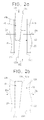
- Figures 2a and 2b diagrammatically show in respective top plan views the first example of the wedge mechanism 10 in a position before and after the wedge parts 41, 42 have been mounted on the guide member 50, respectively.
- the wedge parts 41, 42 are pushed in opposite axial directions as shown by arrows D1, D2 through the guide member 50.
- Axial movement of the wedge parts 41, 42 means herein that the wedge parts 41, 42 are pushed in a direction substantially parallel to that of the longitudinal axis of the rotor.
- the wedge parts 41, 42 are pushed in the opposite axial directions D1, D2 through the guide member 50 until the wedge parts 41, 42 are arranged with their respective inclined planes 41 a, 42a facing each other and substantially in full contact with each other.
- the wedge parts 41, 42 are arranged inversely with their inclined planes 41 a, 42a facing each other, the relative axial displacement of the wedge parts 41, 42 along the guide member 50 results in that the overall width of the wedge element 40 is increased due to the lateral movement of the wedge parts 40, 41 as shown by arrows Da and Db in figures 2a-2b .
- the wedge assembly 10 comprises a wedge element 40 formed with two wedge parts 41, 42 together with a guide member 50
- attachment of the parts that is, the magnet module assembly 20 and the rotor rim 30, is performed as the wedge parts 41, 42 are moved relative to each other along the guide member 50.
- This is advantageous in that the magnet modules in the magnet module assembly 20 can be mounted radially instead of axially as stated above.
- Radial mounting of magnet modules in the magnet module assembly 20 is in any case only possible in this example while the rotor is arranged outside the stator in an assembly stage, but not after final arrangement of the generator. Radial mounting of magnet modules starts when the opposite surfaces 41 b, 42b of the wedge parts 41, 42 are substantially aligned with the outer surfaces of the guide member 50. Then, as the wedge parts 41, 42 are displaced axially to each other (arrows Da and Db) along the guide member 50, they spread outwards such that the opposite surfaces 41 b, 42b of the wedge parts 41, 42 protrude from the outer surfaces of the guide member 50 pressing against the inner surfaces 21 a, 22a of the sectors 21, 22 of the magnet module assembly 20. The magnet module assembly 20 then becomes attached to the rotor rim 30 reaching the above mentioned active position shown in figure 2b .
- the guide member 50 of the mechanism 10 comprises a base member 55 that is attached to the rotor rim 30, for example welded and/or bolted.
- the guide member 50 further comprises two opposite guide portions 51, 52 adapted for receiving at least one wedge element 40 therebetween.
- the guide portions 51, 52 could be formed as a single piece.
- the guide portions 51, 52 may preferably be of an elastic nature.
- the wedge element 40 has opposed inclined planes 41 b.
- the outer surface of the guide portions 51, 52 are adapted to be in direct contact with the respective inner surfaces 21 a, 22a of the opposite sectors 21, 22 of the magnet module assembly 20.
- the wedge element 40 is inserted between the guide portions 51, 52 radially, that is, by being pushed in the direction shown by arrow D3. Radial movement of the wedge element 40 means herein that the wedge element 40 is pushed in a direction substantially perpendicular to that of the longitudinal axis of the rotor.
- Figure 4 shows one variant of the above mentioned second example in figure 3 .
- the wedge element 40 may be inserted between the guide portions 51, 52 axially, that is, in a direction shown by arrow D4 in figure 4 , that is, a direction substantially parallel to that of the longitudinal axis of the rotor.
- the guide portions 51, 52 are arranged inclined to each other as shown in top view in figure 4 and with the guide portions 51, 52 being substantially parallel to the inclined planes 41 a, 42a of the wedge parts 41, 42.
- the wedge element 40 is inserted between the guide portions 51, 52 axially in the direction shown by arrow D4. This causes the guide portions 51, 52 to be forced to open outwards towards the inner surfaces 21 a, 22a of the opposite sectors 21, 22 of the magnet module assembly 20. This results in that the magnet module assembly 20 and the rotor rim 30 are maintained attached to each other (active position of the mechanism 10).
- the guide portions 51, 52 of the guide member 50 may be made thinner in unloaded areas.
- the guide member 50 may be fitted with interference with the magnet module assembly 20 or in contact therewith in the attachment process.
- the reverse relative movement of the wedge parts 41, 42, or the reverse relative movement of the wedge element 40 and the guide portions 51, 52 of the guide member 50 causes the mechanism 10 to reach an inactive position where the magnet module assembly 20 can be disassembled from the rotor rim 30 for maintenance and repair operations.
- the magnet module assembly may be formed of a number of magnet modules.
- the wedge parts of the wedge element may act on sectors of different magnet modules. In other cases, however, the wedge element may act on different sectors of the same magnet module, in use.
Landscapes
- Engineering & Computer Science (AREA)
- Power Engineering (AREA)
- General Engineering & Computer Science (AREA)
- Mechanical Engineering (AREA)
- Life Sciences & Earth Sciences (AREA)
- Sustainable Development (AREA)
- Sustainable Energy (AREA)
- Chemical & Material Sciences (AREA)
- Combustion & Propulsion (AREA)
- Permanent Field Magnets Of Synchronous Machinery (AREA)
- Wind Motors (AREA)
Abstract
Description
- The present disclosure relates to mechanisms for attaching two or more assemblies to each other, in particular in wind turbine applications.
- There are a number of assemblies in wind turbine applications which need to be attached to other assemblies or parts of a wind turbine. For example, in direct drive systems for wind turbines, e.g. offshore wind turbines, which use permanent magnet generators, that is, generators where the excitation field is provided by permanent magnets instead of a coil, a number of magnets are arranged in modules. The magnet modules need to be attached to the wind turbine rotor.
- The attachment of a magnet module to the rotor may be carried out in different ways. The magnet module may be for example attached to the rotor directly, such as by welding, through bolted connections. The magnet module or even the magnets themselves may be attached to the rotor glued to a rotor body, by stamping the ends of the magnets to hold them in place, attached through the use of clamps coupled to the rotor body or directly to the rotor rim, etc.
- One disadvantage with the above ways for attaching the assemblies in a wind turbine is the large amount of welding that is required which is very time consuming and labour intensive.
- A further disadvantage is that a large number of bolts are used. In addition, in attachment by gluing reliability is reduced as it is difficult to ensure attachment of the assemblies over time.
- In order to at least mitigate the above disadvantage, the above ways for attaching the magnets to a wind turbine rotor have been combined with the use of guide means.
- For example, in document
US2008093945 the magnets are inserted longitudinally into guide means. The guide means comprise wedge shaped guide grooves that are formed in the rotor. The guide grooves are adapted for receiving the magnets such that they are distributed at the periphery of the rotor and fastened therein. A medium that hardens by a chemical reaction and/or thermal treatment is provided. Such medium is intended for ensuring the attachment of the magnets in the grooves filling the gaps existing therebetween. - Document
US2009250935 also discloses the use of guide means comprising grooves that are arranged spaced at regular intervals on the rotor. The grooves have a corresponding trapezoidal shape adapted for receiving trapezoidal shaped magnets. The magnets are attached to the rotor by melting portions of the magnets bonded to the rotor by a high temperature atmosphere. - Document
EP2523316 filed by the present applicant discloses a generator rotor having a rotor rim upon which a plurality of permanent magnet modules is arranged extending in an axial direction of the generator rotor. T-shaped anchors are fitted in corresponding grooves that are formed in the wind turbine rotor. Such anchors are provided with bores suitable for accommodating bolts for fixing the anchor to the rotor rim. The permanent magnet modules are inserted between two neighbouring anchors and fixed in place by means of bolts. - The above solutions for attaching different assemblies to each other in a wind turbine have been shown to be reliable and efficient. However, maintenance and repair operations become cumbersome. For example, in the case where the magnets are attached to the wind turbine rotor according to the above disclosed ways, when one or more magnets needs to be replaced, detachment becomes very complicated as bolts are not easily accessible and removal of welding is complex. This hampers maintenance and repair operations rendering them costly. Assembly operations are also complex and time consuming since the bolts are usually locked with glue one by one after they have been completely inserted.
- There is thus a need for a mechanism that is capable of providing an easy attachment and detachment of assemblies in wind turbine applications, such as for example for attaching magnet modules to the rotor, as well as parts of the wind turbine stator, such as poles or active part portions of the wind turbine stator.
- The present mechanism for attaching two assemblies to each other in wind turbine applications has been developed in order to overcome or at least mitigate the above disclosed disadvantages related to prior art solutions. It has been also found that the present mechanism provides a number of additional advantages as it will be disclosed hereinbelow.
- A mechanism for attaching at least a first assembly and a second assembly in wind turbine applications is provided. The first assembly comprises a number of sectors. As used herein, a sector means an area, portion or region of the assembly.
- The first assembly may be, for example, rotor active parts such as a wind turbine magnet module assembly. In this case, a magnet module sector is an area, portion or region of the magnet module.
- The second assembly may be a wind turbine rotor, and specifically a wind turbine rotor rim. Other examples are not ruled out such as those in which the first assembly is a wind turbine stator active part portion and the second assembly is a wind turbine stator structure such a stator housing. The stator active part portion is formed by stator teeth around which a coil is provided.
- The present mechanism is referred herein to as wedge mechanism as it comprises at least one wedge element. A wedge element as used herein is a piece or block having at least one inclined plane.
- The present mechanism further comprises a guide member that is attached to the second assembly. The guide member is adapted for receiving the above mentioned wedge element.
- With the above configuration, at least an inactive position of the mechanism and an active position of the mechanism are defined. In the inactive position of the mechanism the first assembly and the second assembly can be detached from each other, for example for maintenance and repair operations. In the active position of the mechanism at least one of the wedge element and the guide member presses against two different sectors, that is, areas, portions or regions, of the first assembly. The first assembly and the second assembly remain attached to each other ready for operation.
- In some cases, the magnet module assembly may comprise a number of magnet modules. In this particular case, the wedge parts of the wedge element, in use, act on sectors of different magnet modules. In other cases, however, the wedge element, in use, act on different sectors of the same magnet module. In this latter case, there is the advantage that the assemblies formed of magnet modules with the corresponding wedge mechanisms acting on different sectors of the same magnet module are separate from each other. This results in that the assembly and replacing operations are facilitated.
- An effective way to attach and detach two or more assemblies in the wind turbine is obtained as well as a great accessibility both for assembly and maintenance operations. The provision of a guide member results in that assembly time is also reduced since much fewer bolts and welding is required. In addition, there is no need of pins between the assemblies such as the wind turbine rotor and guide member to withstand tangential loads. In the case of attaching parts of the wind turbine stator, the assembly time is reduced as welding is avoided as compared to prior art solutions.
- In preferred examples, the wedge element of the mechanism may comprise at least two wedge parts and the guide member is adapted for slidingly receiving the wedge parts. A relative axial displacement of said wedge parts along the guide member causes the wedge parts to press against two different sectors of the first assembly. The force applied to respective opposite narrow ends of different, adjacent wedge parts is converted into forces perpendicular to the respective inclined surfaces of said wedge parts. This results in that the outer surfaces of the wedge parts press against the opposite sectors of the first assembly such that the first assembly and the second assembly are maintained attached to each other.
- In further examples, the guide member may comprise at least two guide portions. The guide portions of the guide member are adapted for receiving at least one wedge element therebetween. As the wedge element is fitted between the guide portions of the guide member, said guide portions are forced to open outwards towards different sectors of the first assembly. This results in that the first assembly and the second assembly are maintained attached to each other.
- In the above example where the guide member comprises at least two guide portions, the guide portions may be adapted to open outwards towards different sectors of the first assembly when the wedge element is fitted axially therebetween. Still in the above example, the guide portions of the guide member may be adapted to open outwards towards different sectors of the first assembly when the wedge element is fitted radially therebetween. In any case, the wedge element may comprise at least two wedge parts.
- The present mechanism provides an improved feasibility of assembly and fastening operations of the generator active parts such as rotor magnet modules, stator core, etc.
- A generator comprising a stator, a rotor and a number of permanent magnets is also disclosed herein. The generator further comprises the wedge mechanism described above for attaching the magnets to the rotor.
- A wind turbine comprising the above generator having said wedge mechanism for attaching the magnets to the rotor, for attaching stator active part portion to a stator structure, etc.
- Non-limiting examples of the present disclosure will be described in the following, with reference to the appended drawings, in which:
-
Figure 1 diagrammatically shows a sectional view of a first example of the wedge mechanism; -
Figure 2a is a schematic top plan view of the first example of the wedge mechanism offigure 1 shown in a position before being mounted on the guide member; -
Figure 2b is a schematic top plan view of the first example of the wedge mechanism offigure 1 shown in a position already mounted on the guide member; -
Figure 3 diagrammatically shows a sectional view of a second example of the wedge mechanism; and -
Figure 4 is a schematic top plan view of one variant of the second example of the wedge mechanism shown infigure 3 . - The drawings show two non-limiting examples of the
present wedge mechanism 10. In both examples, themechanism 10 shown is intended for attaching a wind turbinemagnet module assembly 20, that is, a whole series of magnet modules, to a windturbine rotor rim 30. Themagnet module assembly 20 comprises a number ofsectors Sectors - The
mechanism 10 shown in the drawings comprises awedge element 40. As shown infigures 2a-2b , thewedge element 40 is a block having at least oneinclined plane - The
mechanism 10 further comprises aguide member 50 that may be manufactured for example by extrusion. Theguide member 50 is attached to therotor rim 30, for example welded and/or bolted. Theguide member 50 is adapted for slidingly receiving thewedge element 40. Thewedge element 40 can be moved, i.e. slide, along theguide member 50. - According to the above general configuration of the
mechanism 10, two examples are shown in the figures. - In the first example shown in
figures 1 and2a-2b , themechanism 10 comprises twowedge parts figures 2a-2b , thewedge parts inclined planes opposite surfaces wedge parts inner surfaces opposite sectors magnet module assembly 20. - The
wedge parts figure 1 have a substantially a L-shaped cross-section while theguide member 50 has a substantially C-shaped cross-section for complementarily receiving the twowedge parts -
Figures 2a and 2b diagrammatically show in respective top plan views the first example of thewedge mechanism 10 in a position before and after thewedge parts guide member 50, respectively. - Starting from the position of the
wedge parts figure 2a , for attaching themagnet module assembly 20 to therotor rim 30, with theguide member 50 already fixed to therotor rim 30, thewedge parts guide member 50. Axial movement of thewedge parts wedge parts wedge parts guide member 50 until thewedge parts inclined planes - Since the
wedge parts inclined planes wedge parts guide member 50 results in that the overall width of thewedge element 40 is increased due to the lateral movement of thewedge parts figures 2a-2b . This results in that theopposite surfaces wedge parts inner surfaces opposite sectors magnet module assembly 20 such that themagnet module assembly 20 is attached to therotor rim 30 reaching the active position of themechanism 10 shown infigure 2b of the drawings. - In the first example shown in
figures 1 and2a-2b where thewedge assembly 10 comprises awedge element 40 formed with twowedge parts guide member 50, attachment of the parts, that is, themagnet module assembly 20 and therotor rim 30, is performed as thewedge parts guide member 50. This is advantageous in that the magnet modules in themagnet module assembly 20 can be mounted radially instead of axially as stated above. - Radial mounting of magnet modules in the
magnet module assembly 20 is in any case only possible in this example while the rotor is arranged outside the stator in an assembly stage, but not after final arrangement of the generator. Radial mounting of magnet modules starts when theopposite surfaces wedge parts guide member 50. Then, as thewedge parts guide member 50, they spread outwards such that theopposite surfaces wedge parts guide member 50 pressing against theinner surfaces sectors magnet module assembly 20. Themagnet module assembly 20 then becomes attached to therotor rim 30 reaching the above mentioned active position shown infigure 2b . - In the second example shown in
figure 3 , theguide member 50 of themechanism 10 comprises abase member 55 that is attached to therotor rim 30, for example welded and/or bolted. Theguide member 50 further comprises twoopposite guide portions wedge element 40 therebetween. In some cases, theguide portions guide portions - In said second example in
figure 3 , thewedge element 40 has opposedinclined planes 41 b. The outer surface of theguide portions inner surfaces opposite sectors magnet module assembly 20. For attaching themagnet module assembly 20 to therotor rim 30, thewedge element 40 is inserted between theguide portions wedge element 40 means herein that thewedge element 40 is pushed in a direction substantially perpendicular to that of the longitudinal axis of the rotor. This causes theguide portions inner surfaces opposite sectors magnet module assembly 20. This results in that themagnet module assembly 20 and therotor rim 30 are maintained attached to each other reaching an active position of themechanism 10. -
Figure 4 shows one variant of the above mentioned second example infigure 3 . In this variant, thewedge element 40 may be inserted between theguide portions figure 4 , that is, a direction substantially parallel to that of the longitudinal axis of the rotor. In this particular case, theguide portions figure 4 and with theguide portions inclined planes wedge parts - In the above variant shown in
figure 4 , for attaching themagnet module assembly 20 to therotor rim 30, thewedge element 40 is inserted between theguide portions guide portions inner surfaces opposite sectors magnet module assembly 20. This results in that themagnet module assembly 20 and therotor rim 30 are maintained attached to each other (active position of the mechanism 10). - According the above mentioned second example shown in
figures 3 and4 , theguide portions guide member 50 may be made thinner in unloaded areas. In general, theguide member 50 may be fitted with interference with themagnet module assembly 20 or in contact therewith in the attachment process. - The reverse relative movement of the
wedge parts wedge element 40 and theguide portions guide member 50 causes themechanism 10 to reach an inactive position where themagnet module assembly 20 can be disassembled from therotor rim 30 for maintenance and repair operations. - Although only a number of examples have been disclosed herein, other alternatives, modifications, uses and/or equivalents thereof are possible. For example, the magnet module assembly may be formed of a number of magnet modules. In use, the wedge parts of the wedge element may act on sectors of different magnet modules. In other cases, however, the wedge element may act on different sectors of the same magnet module, in use.
- All possible combinations of the described examples are also covered. Thus, the scope of the present disclosure should not be limited by particular examples, but should be determined only by a fair reading of the claims that follow.
Claims (12)
- Wedge mechanism for attaching at least a first assembly, the first assembly comprising a number of sectors, and a second assembly, the mechanism comprising at least one wedge element and a guide member, the guide member being attached to the second assembly and adapted for receiving the wedge element in a way that and at least an inactive position and an active position of the mechanism are defined, such that in the inactive position the first and second assemblies can be detached from each other and in the active position at least one of the wedge element and the guide member presses against two different sectors of the first assembly such that the first assembly and the second assembly remain attached to each other.
- Wedge mechanism as claimed in claim 1, wherein the wedge element comprises at least two wedge parts and the guide member is adapted for slidingly receiving the wedge parts such that a relative axial displacement thereof along the guide member causes the wedge parts to press against two different sectors of the first assembly such that the first assembly and the second assembly are maintained attached to each other.
- Wedge mechanism as claimed in claim 1, wherein the guide member comprises at least two guide portions for receiving at least one wedge element therebetween causing the guide portions to open outwards towards different sectors of the first assembly such that the first assembly and the second assembly are maintained attached to each other.
- Wedge mechanism as claimed in claim 3, wherein the guide member comprises at least two guide portions adapted to open outwards towards different sectors of the first assembly when the wedge element is fitted axially therebetween.
- Wedge mechanism as claimed in claim 3, wherein the guide member comprises at least two guide portions adapted to open outwards towards different sectors of the first assembly when the wedge element is fitted radially therebetween.
- Wedge mechanism as claimed in any of the claims 3-5, wherein the wedge element comprises at least two wedge parts.
- Wedge mechanism as claimed in any of the preceding claims, wherein the first assembly is a wind turbine magnet module assembly and the second assembly is a wind turbine rotor rim.
- Wedge mechanism as claimed in claim 7, wherein the magnet module assembly comprises a number of magnet modules such that, in use, the wedge parts of the wedge element act on sectors of different magnet modules.
- Wedge mechanism as claimed in claim 7, wherein, in use, the wedge element act on different sectors of the same magnet module.
- Wedge mechanism as claimed in any of the preceding claims, wherein the first assembly is a wind turbine stator active part portion and the second assembly is a wind turbine stator structure.
- A generator comprising a stator, a rotor and a number of permanent magnets, wherein it further comprises a wedge mechanism as claimed in any of the preceding claims for attaching the magnets to the rotor.
- Wind turbine comprising the generator of claim 11.
Priority Applications (2)
| Application Number | Priority Date | Filing Date | Title |
|---|---|---|---|
| EP14382175.9A EP2947752A1 (en) | 2014-05-19 | 2014-05-19 | Wedge mechanism |
| US14/697,580 US10103590B2 (en) | 2014-05-19 | 2015-04-27 | Permanent magnet rotor assembly for a wind turbine using a wedge attachment mechanism |
Applications Claiming Priority (1)
| Application Number | Priority Date | Filing Date | Title |
|---|---|---|---|
| EP14382175.9A EP2947752A1 (en) | 2014-05-19 | 2014-05-19 | Wedge mechanism |
Publications (1)
| Publication Number | Publication Date |
|---|---|
| EP2947752A1 true EP2947752A1 (en) | 2015-11-25 |
Family
ID=50828846
Family Applications (1)
| Application Number | Title | Priority Date | Filing Date |
|---|---|---|---|
| EP14382175.9A Withdrawn EP2947752A1 (en) | 2014-05-19 | 2014-05-19 | Wedge mechanism |
Country Status (2)
| Country | Link |
|---|---|
| US (1) | US10103590B2 (en) |
| EP (1) | EP2947752A1 (en) |
Cited By (3)
| Publication number | Priority date | Publication date | Assignee | Title |
|---|---|---|---|---|
| CN108696017A (en) * | 2018-07-04 | 2018-10-23 | 北京金风科创风电设备有限公司 | Carrier plate, rectifying module, batten strip, rotor, manufacturing method of rotor and motor |
| CN108880034A (en) * | 2018-07-04 | 2018-11-23 | 北京金风科创风电设备有限公司 | Rotor, assembling method and replacing method of whole-pole module of rotor and motor |
| CN110145441A (en) * | 2019-06-19 | 2019-08-20 | 吉林大学 | A guiding and positioning device for air docking of fan impeller assembly and nacelle |
Families Citing this family (1)
| Publication number | Priority date | Publication date | Assignee | Title |
|---|---|---|---|---|
| JP7476001B2 (en) * | 2020-07-09 | 2024-04-30 | Nittoku株式会社 | Winding device and winding method |
Citations (8)
| Publication number | Priority date | Publication date | Assignee | Title |
|---|---|---|---|---|
| EP1750349A1 (en) * | 2005-08-02 | 2007-02-07 | Zf Friedrichshafen Ag | Fastening of permanent magnets onto a rotor |
| US20080093945A1 (en) | 2006-10-21 | 2008-04-24 | Esw Gmbh | Arrangement for fastening permanent magnets to rapidly rotating rotors of electric machines |
| US20090250935A1 (en) | 2006-04-14 | 2009-10-08 | Unison Co., Ltd. | Rotor for wind turbine and assembling method thereof |
| EP2144350A2 (en) * | 2008-07-11 | 2010-01-13 | Robert Bosch GmbH | Rotor for an electric motor and method for its production |
| US20100231085A1 (en) * | 2009-03-10 | 2010-09-16 | Drs Power Technology, Inc. | Pole Retention Configuration For Electric Machine Rotors |
| EP2498376A1 (en) * | 2011-03-10 | 2012-09-12 | Wilic S.ar.l. | "Wind turbine rotary electric machine" |
| EP2523316A1 (en) | 2011-05-11 | 2012-11-14 | Alstom Wind, S.L.U. | Generator rotor, manufacturing method and related insertion tool |
| EP2555381A1 (en) * | 2011-08-01 | 2013-02-06 | Siemens Aktiengesellschaft | Permanent magnet assembly with flanged cover and method for fixing a permanent magnet onto a base plate |
Family Cites Families (7)
| Publication number | Priority date | Publication date | Assignee | Title |
|---|---|---|---|---|
| US7355309B2 (en) | 2004-08-06 | 2008-04-08 | Northern Power Systems, Inc. | Permanent magnet rotor for a direct drive generator or a low speed motor |
| US7573168B2 (en) | 2005-10-24 | 2009-08-11 | General Electric Company | Method and apparatus for assembling a permanent magnet pole assembly |
| EP2348612A1 (en) | 2010-01-20 | 2011-07-27 | Siemens Aktiengesellschaft | Magnetic component part for a rotor assembly |
| DK2348619T3 (en) * | 2010-01-20 | 2014-10-13 | Siemens Ag | Magnetic Device |
| EP2458714B1 (en) | 2010-11-26 | 2017-03-22 | Siemens Aktiengesellschaft | Wedge for a stator of a generator with preformed coil windings |
| US9046081B2 (en) * | 2011-12-07 | 2015-06-02 | Envision Energy (Denmark) Aps | Wind turbine with sealed off stator chamber |
| EP2648316B1 (en) | 2012-04-03 | 2020-05-27 | Siemens Gamesa Renewable Energy A/S | Rotor arrangement |
-
2014
- 2014-05-19 EP EP14382175.9A patent/EP2947752A1/en not_active Withdrawn
-
2015
- 2015-04-27 US US14/697,580 patent/US10103590B2/en not_active Expired - Fee Related
Patent Citations (8)
| Publication number | Priority date | Publication date | Assignee | Title |
|---|---|---|---|---|
| EP1750349A1 (en) * | 2005-08-02 | 2007-02-07 | Zf Friedrichshafen Ag | Fastening of permanent magnets onto a rotor |
| US20090250935A1 (en) | 2006-04-14 | 2009-10-08 | Unison Co., Ltd. | Rotor for wind turbine and assembling method thereof |
| US20080093945A1 (en) | 2006-10-21 | 2008-04-24 | Esw Gmbh | Arrangement for fastening permanent magnets to rapidly rotating rotors of electric machines |
| EP2144350A2 (en) * | 2008-07-11 | 2010-01-13 | Robert Bosch GmbH | Rotor for an electric motor and method for its production |
| US20100231085A1 (en) * | 2009-03-10 | 2010-09-16 | Drs Power Technology, Inc. | Pole Retention Configuration For Electric Machine Rotors |
| EP2498376A1 (en) * | 2011-03-10 | 2012-09-12 | Wilic S.ar.l. | "Wind turbine rotary electric machine" |
| EP2523316A1 (en) | 2011-05-11 | 2012-11-14 | Alstom Wind, S.L.U. | Generator rotor, manufacturing method and related insertion tool |
| EP2555381A1 (en) * | 2011-08-01 | 2013-02-06 | Siemens Aktiengesellschaft | Permanent magnet assembly with flanged cover and method for fixing a permanent magnet onto a base plate |
Cited By (4)
| Publication number | Priority date | Publication date | Assignee | Title |
|---|---|---|---|---|
| CN108696017A (en) * | 2018-07-04 | 2018-10-23 | 北京金风科创风电设备有限公司 | Carrier plate, rectifying module, batten strip, rotor, manufacturing method of rotor and motor |
| CN108880034A (en) * | 2018-07-04 | 2018-11-23 | 北京金风科创风电设备有限公司 | Rotor, assembling method and replacing method of whole-pole module of rotor and motor |
| CN110145441A (en) * | 2019-06-19 | 2019-08-20 | 吉林大学 | A guiding and positioning device for air docking of fan impeller assembly and nacelle |
| CN110145441B (en) * | 2019-06-19 | 2023-08-22 | 吉林大学 | A guiding and positioning device for air docking of fan impeller assembly and nacelle |
Also Published As
| Publication number | Publication date |
|---|---|
| US20150333585A1 (en) | 2015-11-19 |
| US10103590B2 (en) | 2018-10-16 |
Similar Documents
| Publication | Publication Date | Title |
|---|---|---|
| US10958118B2 (en) | Method of assembling a generator rotor of a generator | |
| US10103590B2 (en) | Permanent magnet rotor assembly for a wind turbine using a wedge attachment mechanism | |
| CN105122596B (en) | With the single section rotor and manufacture method by bending single section that carrier is kept | |
| US11196311B2 (en) | Electric generator having multiple electrical machines | |
| US9825507B2 (en) | Generator for a wind turbine | |
| CN104412491B (en) | Stator arrangement for motor | |
| CN103155361A (en) | Spring elements for mechanically securing the magnets in the rotor | |
| US10727705B2 (en) | Compression band shim pack for stator core, related stator and generator | |
| CN105226859B (en) | A kind of rotor structure of the oblique pole of magneto V-arrangement | |
| JP5010734B2 (en) | Wind power generator and assembly method thereof | |
| CN116317244A (en) | Salient pole motor | |
| CN102089515A (en) | Wind turbine comprising a main bearing and method for replacement of the main bearing | |
| US10840753B2 (en) | Magnet module and electrical machine | |
| KR20070033037A (en) | Electric machine | |
| EP3001542B1 (en) | Permanent magnet rotors | |
| KR20200031030A (en) | Permanent magnet modules for an electric machine | |
| CN103548241B (en) | Generator rotor and method of assembly | |
| US20120032547A1 (en) | Magnet ring of a multi-pole generator for a wind turbine | |
| US20230231426A1 (en) | Segment support structure for a generator of a wind turbine | |
| US20170282311A1 (en) | Optimized method and device for crimping attachment of an abradable piece support to a radially inner wall of a vane sector of a turbomachine | |
| KR20180092965A (en) | Radial turbine impeller and method of manufacturing the same | |
| EP3107194A1 (en) | Supporting device and method for supporting winding coils in a wind turbine generator | |
| CN102957252A (en) | Rotating electric machine | |
| US12206299B2 (en) | Method for assembling large-diameter electric motor | |
| WO2025128960A1 (en) | Electric motor with segmented laminated rotor sections |
Legal Events
| Date | Code | Title | Description |
|---|---|---|---|
| PUAI | Public reference made under article 153(3) epc to a published international application that has entered the european phase |
Free format text: ORIGINAL CODE: 0009012 |
|
| AK | Designated contracting states |
Kind code of ref document: A1 Designated state(s): AL AT BE BG CH CY CZ DE DK EE ES FI FR GB GR HR HU IE IS IT LI LT LU LV MC MK MT NL NO PL PT RO RS SE SI SK SM TR |
|
| AX | Request for extension of the european patent |
Extension state: BA ME |
|
| 17P | Request for examination filed |
Effective date: 20160525 |
|
| RBV | Designated contracting states (corrected) |
Designated state(s): AL AT BE BG CH CY CZ DE DK EE ES FI FR GB GR HR HU IE IS IT LI LT LU LV MC MK MT NL NO PL PT RO RS SE SI SK SM TR |
|
| STAA | Information on the status of an ep patent application or granted ep patent |
Free format text: STATUS: EXAMINATION IS IN PROGRESS |
|
| 17Q | First examination report despatched |
Effective date: 20170102 |
|
| RAP1 | Party data changed (applicant data changed or rights of an application transferred) |
Owner name: GE RENEWABLE TECHNOLOGIES WIND B.V. |
|
| STAA | Information on the status of an ep patent application or granted ep patent |
Free format text: STATUS: THE APPLICATION IS DEEMED TO BE WITHDRAWN |
|
| 18D | Application deemed to be withdrawn |
Effective date: 20191009 |