EP2947751A1 - Electromagnetic induction type power supply device - Google Patents
Electromagnetic induction type power supply device Download PDFInfo
- Publication number
- EP2947751A1 EP2947751A1 EP14740166.5A EP14740166A EP2947751A1 EP 2947751 A1 EP2947751 A1 EP 2947751A1 EP 14740166 A EP14740166 A EP 14740166A EP 2947751 A1 EP2947751 A1 EP 2947751A1
- Authority
- EP
- European Patent Office
- Prior art keywords
- power
- current
- unit
- electromagnetic induction
- power supply
- Prior art date
- Legal status (The legal status is an assumption and is not a legal conclusion. Google has not performed a legal analysis and makes no representation as to the accuracy of the status listed.)
- Granted
Links
Images

Classifications
-
- H—ELECTRICITY
- H02—GENERATION; CONVERSION OR DISTRIBUTION OF ELECTRIC POWER
- H02M—APPARATUS FOR CONVERSION BETWEEN AC AND AC, BETWEEN AC AND DC, OR BETWEEN DC AND DC, AND FOR USE WITH MAINS OR SIMILAR POWER SUPPLY SYSTEMS; CONVERSION OF DC OR AC INPUT POWER INTO SURGE OUTPUT POWER; CONTROL OR REGULATION THEREOF
- H02M1/00—Details of apparatus for conversion
- H02M1/32—Means for protecting converters other than automatic disconnection
-
- H—ELECTRICITY
- H01—ELECTRIC ELEMENTS
- H01F—MAGNETS; INDUCTANCES; TRANSFORMERS; SELECTION OF MATERIALS FOR THEIR MAGNETIC PROPERTIES
- H01F38/00—Adaptations of transformers or inductances for specific applications or functions
- H01F38/20—Instruments transformers
- H01F38/22—Instruments transformers for single phase AC
- H01F38/28—Current transformers
-
- H—ELECTRICITY
- H02—GENERATION; CONVERSION OR DISTRIBUTION OF ELECTRIC POWER
- H02J—ELECTRIC POWER NETWORKS; CIRCUIT ARRANGEMENTS OR SYSTEMS FOR SUPPLYING OR DISTRIBUTING ELECTRIC POWER; SYSTEMS FOR STORING ELECTRIC ENERGY
- H02J50/00—Circuit arrangements or systems for wireless supply or distribution of electric power
- H02J50/001—Energy harvesting or scavenging
-
- H—ELECTRICITY
- H02—GENERATION; CONVERSION OR DISTRIBUTION OF ELECTRIC POWER
- H02J—ELECTRIC POWER NETWORKS; CIRCUIT ARRANGEMENTS OR SYSTEMS FOR SUPPLYING OR DISTRIBUTING ELECTRIC POWER; SYSTEMS FOR STORING ELECTRIC ENERGY
- H02J50/00—Circuit arrangements or systems for wireless supply or distribution of electric power
- H02J50/10—Circuit arrangements or systems for wireless supply or distribution of electric power using inductive coupling
-
- H—ELECTRICITY
- H02—GENERATION; CONVERSION OR DISTRIBUTION OF ELECTRIC POWER
- H02M—APPARATUS FOR CONVERSION BETWEEN AC AND AC, BETWEEN AC AND DC, OR BETWEEN DC AND DC, AND FOR USE WITH MAINS OR SIMILAR POWER SUPPLY SYSTEMS; CONVERSION OF DC OR AC INPUT POWER INTO SURGE OUTPUT POWER; CONTROL OR REGULATION THEREOF
- H02M5/00—Conversion of AC power input into AC power output, e.g. for change of voltage, for change of frequency, for change of number of phases
- H02M5/02—Conversion of AC power input into AC power output, e.g. for change of voltage, for change of frequency, for change of number of phases without intermediate conversion into DC
- H02M5/04—Conversion of AC power input into AC power output, e.g. for change of voltage, for change of frequency, for change of number of phases without intermediate conversion into DC by static converters
- H02M5/10—Conversion of AC power input into AC power output, e.g. for change of voltage, for change of frequency, for change of number of phases without intermediate conversion into DC by static converters using transformers
- H02M5/12—Conversion of AC power input into AC power output, e.g. for change of voltage, for change of frequency, for change of number of phases without intermediate conversion into DC by static converters using transformers for conversion of voltage or current amplitude only
-
- H—ELECTRICITY
- H02—GENERATION; CONVERSION OR DISTRIBUTION OF ELECTRIC POWER
- H02M—APPARATUS FOR CONVERSION BETWEEN AC AND AC, BETWEEN AC AND DC, OR BETWEEN DC AND DC, AND FOR USE WITH MAINS OR SIMILAR POWER SUPPLY SYSTEMS; CONVERSION OF DC OR AC INPUT POWER INTO SURGE OUTPUT POWER; CONTROL OR REGULATION THEREOF
- H02M7/00—Conversion of AC power input into DC power output; Conversion of DC power input into AC power output
- H02M7/02—Conversion of AC power input into DC power output without possibility of reversal
- H02M7/04—Conversion of AC power input into DC power output without possibility of reversal by static converters
- H02M7/06—Conversion of AC power input into DC power output without possibility of reversal by static converters using discharge tubes without control electrode or semiconductor devices without control electrode
- H02M7/08—Conversion of AC power input into DC power output without possibility of reversal by static converters using discharge tubes without control electrode or semiconductor devices without control electrode arranged for operation in parallel
-
- H—ELECTRICITY
- H04—ELECTRIC COMMUNICATION TECHNIQUE
- H04B—TRANSMISSION
- H04B5/00—Near-field transmission systems, e.g. inductive or capacitive transmission systems
- H04B5/20—Near-field transmission systems, e.g. inductive or capacitive transmission systems characterised by the transmission technique; characterised by the transmission medium
- H04B5/24—Inductive coupling
-
- H—ELECTRICITY
- H02—GENERATION; CONVERSION OR DISTRIBUTION OF ELECTRIC POWER
- H02M—APPARATUS FOR CONVERSION BETWEEN AC AND AC, BETWEEN AC AND DC, OR BETWEEN DC AND DC, AND FOR USE WITH MAINS OR SIMILAR POWER SUPPLY SYSTEMS; CONVERSION OF DC OR AC INPUT POWER INTO SURGE OUTPUT POWER; CONTROL OR REGULATION THEREOF
- H02M1/00—Details of apparatus for conversion
- H02M1/32—Means for protecting converters other than automatic disconnection
- H02M1/325—Means for protecting converters other than automatic disconnection with means for allowing continuous operation despite a fault, i.e. fault tolerant converters
-
- H—ELECTRICITY
- H02—GENERATION; CONVERSION OR DISTRIBUTION OF ELECTRIC POWER
- H02M—APPARATUS FOR CONVERSION BETWEEN AC AND AC, BETWEEN AC AND DC, OR BETWEEN DC AND DC, AND FOR USE WITH MAINS OR SIMILAR POWER SUPPLY SYSTEMS; CONVERSION OF DC OR AC INPUT POWER INTO SURGE OUTPUT POWER; CONTROL OR REGULATION THEREOF
- H02M5/00—Conversion of AC power input into AC power output, e.g. for change of voltage, for change of frequency, for change of number of phases
- H02M5/02—Conversion of AC power input into AC power output, e.g. for change of voltage, for change of frequency, for change of number of phases without intermediate conversion into DC
- H02M5/04—Conversion of AC power input into AC power output, e.g. for change of voltage, for change of frequency, for change of number of phases without intermediate conversion into DC by static converters
- H02M5/22—Conversion of AC power input into AC power output, e.g. for change of voltage, for change of frequency, for change of number of phases without intermediate conversion into DC by static converters using discharge tubes with control electrode or semiconductor devices with control electrode
- H02M5/225—Conversion of AC power input into AC power output, e.g. for change of voltage, for change of frequency, for change of number of phases without intermediate conversion into DC by static converters using discharge tubes with control electrode or semiconductor devices with control electrode comprising two stages of AC-AC conversion, e.g. having a high frequency intermediate link
-
- H—ELECTRICITY
- H02—GENERATION; CONVERSION OR DISTRIBUTION OF ELECTRIC POWER
- H02M—APPARATUS FOR CONVERSION BETWEEN AC AND AC, BETWEEN AC AND DC, OR BETWEEN DC AND DC, AND FOR USE WITH MAINS OR SIMILAR POWER SUPPLY SYSTEMS; CONVERSION OF DC OR AC INPUT POWER INTO SURGE OUTPUT POWER; CONTROL OR REGULATION THEREOF
- H02M7/00—Conversion of AC power input into DC power output; Conversion of DC power input into AC power output
- H02M7/42—Conversion of DC power input into AC power output without possibility of reversal
- H02M7/44—Conversion of DC power input into AC power output without possibility of reversal by static converters
- H02M7/48—Conversion of DC power input into AC power output without possibility of reversal by static converters using discharge tubes with control electrode or semiconductor devices with control electrode
- H02M7/4807—Conversion of DC power input into AC power output without possibility of reversal by static converters using discharge tubes with control electrode or semiconductor devices with control electrode having a high frequency intermediate AC stage
Definitions
- the present disclosure relates to an electromagnetic induction type power supply device, and more particularly, to an electromagnetic induction type power supply device, which generates necessary power through an electromagnetic induction method using a current transformer from an current flowing through a transmission line, may adjust an output by detecting and an output voltage and current and providing feedback, enables a current transformer and a power converting unit to be added or removed as necessary, thereby increasing availability, and can supply power stably.
- an electromagnetic induction type power supply device that is based on a current transformer is installed on a power link in which a large amount of current flows, such as a power line, a bare conductor line or a busbar, to induce a current from the power link, generate power by using the induced current and supply actuating power to equipment needing power (hereinafter, referred to as "power-needing equipment").
- power-needing equipment equipment needing power
- a typical current induction type power supply device includes a current transformer that induces an alternating current (AC) current from the power link, and a rectifier that converts the AC current induced from the current transformer into direct current (DC) power and transmits the DC power to a device needing power (hereinafter, referred to as "power-needing device").
- AC alternating current
- DC direct current
- Embodiments provide an electromagnetic induction type power supply device that may enable a current transformer or a power converting unit and the current transformer to be simply added or removed in a situation in which the main power supply of a power link normally operates as necessary, to linearly increase or decrease power capable of being generated to always secure minimum power needed by a power-needing device, have control and protection functions of preventing an internal power generation circuit from generating over-current or excessive power to prevent equipment from malfunctioning and becoming damaged, arbitrarily adjust the maximum output of each current transformer and supply power depending on the situation.
- the number of the plurality of current transformers of the current transformer module and the number of the plurality of power converting units of the power supply module may vary according to a specification of a device requiring power.
- the power converting unit may include a primary rectifier unit converting induced power provided from the current transformer into a DC voltage; a switching circuit unit switching and outputting the DC voltage converted by the primary rectifier unit by pulse width modulation; and a secondary rectifier unit converting, into a DC voltage, a voltage inducted by the voltage output from the switching circuit unit.
- the primary rectifier unit may convert induced power provided from the current transformer into a DC voltage to provide the DC voltage to the switching circuit unit when a size of the current provided from the current transformer is within a preset size of a reference current. Also, the primary rectifier unit may interrupt or bypass a current exceeding the range of the reference current to perform a protection function against from an over-current.
- the power converting unit further comprises a feedback circuit unit that receives an output of the secondary rectifier unit and an output of the power summing unit as feedback and controls pulse width duty of pulse width modulation performed by the switching circuit unit.
- the current transformer may be a separable current transformer that is added to or removed from the line, and the power converting unit may further include a damping circuit unit for adjusting magnetization of the current transformer to be separated from the line of the current transformer.
- the electromagnetic induction type power supply device may further include a DC/alternating current (AC) converting unit converting an output of the power summing unit into AC power.
- AC alternating current
- the present invention by generating main power through an electromagnetic induction method from a current flowing in a line and supplying the power to power-needing equipment, it is possible to stably supply power irrespective of a current flowing in the line, and by adding or removing a current transformer and a power supply device irrespective of a line current easily as necessary, it is possible to enhance the easiness of power management.
- the present invention even when the power demand of power-needing equipment changes, it is possible to secure necessary power by simply adding or removing a current transformer or power converting unit and the current transformer, and by using a separable current transformer that may be added and removed, it is also possible to increase the convenience of installation and management irrespective of the condition of a distribution line.
- the output of each of a plurality of power supply devices and a final output obtained by summing the outputs of the plurality of power supply devices are redundantly feedback to be reflected to power control, it is possible to enhance the stability of a product and it is also possible to provide the final output constantly to enhance output quality even when the performance of each current transformer is not constant.
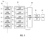
- FIG. 1 is a block diagram of an electromagnetic induction type power supply device according to an embodiment of the present invention.
- the electromagnetic induction type power supply device may include a current transformer module 20, a power supply module 30, and a power summing unit 40.
- the current transformer module 20 may include a plurality of current transformers 21 to 25.
- Each of the plurality of current transformers 21 to 25 may induce a current from a power link in which a large amount of currents flows, such as a power line, a bare conductor line, or a busbar.
- the power link in which the large amount of currents flows may be referred to as a line.
- the current transformers 21 to 25 may include a secondary winding that may induce a primary current flowing in a line that is a primary winding, and output the induced current to the secondary winding by electromagnetic induction according to the large amount of currents flowing in the primary winding.
- the power supply module 30 may receive a secondary current induced and output by electromagnetic induction at the plurality of current transformers 21 to 25 in the current transformer module 20, convert the received current into a direct current (DC) voltage having a desired size, and output the converted current.
- the power supply module 30 may include a plurality of power converting units 31 to 35 that receives the secondary current output from each of the current transformers 21 to 25 and converts the received current.
- Each of the plurality of power converting units 31 to 35 may receive the secondary current output from one or a plurality of current transformers 21 to 25, convert the received current to a DC current and output the DC current.
- the power supply module 30 may be implemented to be capable of changing the number of the power converting units. That is, it is possible to add or remove the power converting units 31 to 35 in the power supply module 30 according to the size of power required by a load 60 so that approximate power required by a power-needing device may be output.
- FIG. 2 is a detailed block diagram of a power converting unit in an electromagnetic induction type power supply device according to an embodiment of the present invention.
- the power converting unit 31 may include a filter unit 311, a primary rectifier unit 312, a control unit 313, a secondary rectifier unit 314, and a feedback circuit unit 315.
- the power converting unit 31 may further include a damping circuit unit 316 for the magnetization control of the current transformers 21 to 25 that enables the addition and removal of the current transformers 21 to 25.
- the filter unit 311 is used for performing filtering on an induced current output from the current transformers 21 to 25 that provides secondary current, and is a filter for removing electromagnetic interference (EMI) or other noise.
- EMI electromagnetic interference
- the primary rectifier unit 312 may convert power received from the current transformers 21 to 25 into a DC voltage.
- the primary rectifier unit 312 may include a bridge diode and a smoothing capacitor.
- the primary rectifier unit 312 may transmit power to the next stage when the size of a voltage or current received from the current transformers 21 to 25 is within a preset reference size.
- the size of the reference current may be adjusted by external manipulation and thus it is possible to adjust maximum power that may be supplied by a single power converting unit. By interrupting or bypassing a current exceeding the reference current, the primary rectifier unit 312 may prevent the output of excessive power and perform a protection function.
- the switching circuit unit 313 may adjust the duty of a switching device therein by using pulse width modulation (PWM) to provide a DC voltage.
- PWM pulse width modulation
- the switching circuit unit 313 may be implemented in a PWM control integrated circuit (IC) that includes the switching device (e.g., MOSFET) therein.
- the secondary rectifier unit 313 may include a transformer that has a primary winding receiving the power of the primary rectifier unit 312 provided by the switching circuit unit 313 and a secondary winding electromagnetically coupled to the primary winding and outputting a current induced by a current flowing in the primary winding, and a diode that rectifies and smoothes a voltage induced to the secondary winding of the transformer.
- the secondary rectifier unit 313 may rectify the voltage value of power provided via the switching circuit unit 313 to a preset size.
- the secondary rectifier unit 313 may provide, to the feedback circuit unit 315, the output of the secondary rectifier unit 313 capable of varying according to the size of the load 60 so that the output does not significantly vary according to a load variation.
- the feedback circuit unit 315 may perform a protection operation of resetting the switching operation of the switching circuit unit 313 when AC power provided by the current transformers 21 to 25 has overvoltage. Also, the feedback circuit unit 315 may detect and receive the size of the output of the power converting unit 31 provided from the secondary rectifier unit 314 to the power summing unit 40 and adjust the duty of the switching circuit unit 313 to be capable of maintaining the size of an output voltage constantly.
- the feedback circuit unit 315 may detect and receive the size of a voltage and current provided from the power summing unit 40 to the load 60, and perform a protection operation such as stopping or resetting the operation of the switching circuit unit 313 for system protection when a final output voltage provided to the load 60 excessively increases.
- the power summing unit 40 sums power output to each of the power converting units 31 to 35 in the power supply module 30 and provides the summed power to the load 60. Also, the power summing unit 40 may provide the size of a final output voltage to the feedback circuit 315 of the power converting units 31 to 35 to control the operation of each power converting unit 35 according to the final output voltage.
- an embodiment of the present invention may further include a DC/AC converting unit that converts DC power output from the power summing unit 40 into AC power.
- a DC/AC converting unit that converts DC power output from the power summing unit 40 into AC power.
- an embodiment of the present invention may selectively include the DC/AC converting unit 50 to provide an appropriate type of power required by the load 60.
- the power converting unit 31 may include a damping circuit unit 316.
- the damping circuit unit 316 may be installed for the replacement of the current transformers 21 to 25 to which the power converting unit 31 to which the damping circuit unit belongs is connected.
- the current transformers having a separable structure are mutually coupled by an induced magnetic force by an induced voltage occurring at each current transformer and thus it is not easy to separate them by a physical force. That is, since it is significantly difficult to separate the current transformers having the separable structure when a current flows in a line, it is difficult to separate the current transformers without interrupting the current flowing in the line.
- An embodiment of the present invention includes the damping circuit unit 316 for controlling the induced magnetism of a current transformer as necessary. By including such a damping circuit unit 316, an embodiment of the present invention may easily add or remove a current transformer having a separable structure even in a situation in which a line current flows.
- each CT output having non-uniform performance interferes with one another and thus there is a limitation in that an output decreases or is non-uniform
- the design of the power supply unit involves a high-current design, there are limitations in that it is difficult to design the power supply unit and the power supply design adversely affects performance
- an embodiment of the present invention may design so that one current transformer corresponds to one power converting unit, it is possible to enhance the performance of a product and it is also possible to easily adjust the final output because there is only a need to add the current transformer or power converting unit according to a desired output.
- an electromagnetic induction type power supply device may apply to various work sites because it is possible to set an output according to the situation of a line current, be used as the main power supply of various pieces of equipment needing power because desired power is sufficiently secured when only a line current equal to or more than e.g., 15 A is secured.
Landscapes
- Engineering & Computer Science (AREA)
- Power Engineering (AREA)
- Computer Networks & Wireless Communication (AREA)
- Signal Processing (AREA)
- Dc-Dc Converters (AREA)
- Rectifiers (AREA)
Abstract
Description
- The present disclosure relates to an electromagnetic induction type power supply device, and more particularly, to an electromagnetic induction type power supply device, which generates necessary power through an electromagnetic induction method using a current transformer from an current flowing through a transmission line, may adjust an output by detecting and an output voltage and current and providing feedback, enables a current transformer and a power converting unit to be added or removed as necessary, thereby increasing availability, and can supply power stably.
- In general, an electromagnetic induction type power supply device that is based on a current transformer is installed on a power link in which a large amount of current flows, such as a power line, a bare conductor line or a busbar, to induce a current from the power link, generate power by using the induced current and supply actuating power to equipment needing power (hereinafter, referred to as "power-needing equipment").
- A typical current induction type power supply device includes a current transformer that induces an alternating current (AC) current from the power link, and a rectifier that converts the AC current induced from the current transformer into direct current (DC) power and transmits the DC power to a device needing power (hereinafter, referred to as "power-needing device").
- However, such a typical power supply device has the following limitations.
- (1) Since a current flowing in the power link is interrupted when the power link is out of order, is replaced or repaired, an induced current is not generated and thus there is a limitation in that it is difficult to supply power.
- (2) When a typical cylindrical current transformer is used, there is a limitation in that there is a need for the current transformer to be installed or separated when the power link is initially installed or artificially after power supply to the power link is cut off.
- (3) When the load of the power-needing device changes, there is a limitation in that there is a need for a new power supply device to be designed and manufactured because it is difficult to increase and decrease the output of a power supply device as necessary.
- (4) Since power generated in the process of inducing over-current by the current transformer is transmitted to the power-needing device as it is or is not used up by the power supply device for a necessary time, there is a limitation that adversely affects the lifespan of power-needing equipment or the lifespan of the power supply device.
- (5) Even if over-current is not generated by the current transformer, there is a limitation that adversely affects the power supply device and the power-needing equipment by generating and supplying unnecessary power because there is no need to supply power exceeding power needed by the power-needing device.
- (6) Even when the size of a current flowing in a general power link decreases to 15 A, it is possible to configure a system that may supply power to a minimum of a power-needing device only when each current transformer has to generate at least 1.2 W or more power, but since most typical current transformer based power supply devices need a minimum power link current of 30 A or more, depends on a switch operation according to the size of a line current or has an auxiliary battery for the operating source of an internal power supply device, there is a limitation in application places that do not correspond to the needs of the minimum current of the general power link.
- (7) In a structure that includes a plurality of current transformers, the outputs of the current transformers are connected in parallel to be connected directly to a single power supply module unit to increase an output, but when the current transformers do not have the same characteristics, the output summed by interaction does not linearly increase and thus there is a limitation in that the uniformity of the output quality of a power supply device decreases.
- (8) Since a typical electromagnetic induction type power supply device is designed and manufactured in such a manner that a current transformer and a power converting unit independently operate, there are limitations in that it is difficult to perform module-dependent management according to individual performance and output and even the same system experiences a significant variation in performance according to installation methods and orders.
- Embodiments provide an electromagnetic induction type power supply device that may enable a current transformer or a power converting unit and the current transformer to be simply added or removed in a situation in which the main power supply of a power link normally operates as necessary, to linearly increase or decrease power capable of being generated to always secure minimum power needed by a power-needing device, have control and protection functions of preventing an internal power generation circuit from generating over-current or excessive power to prevent equipment from malfunctioning and becoming damaged, arbitrarily adjust the maximum output of each current transformer and supply power depending on the situation.
- In one embodiment,
- an electromagnetic induction type power supply device includes:
- a current transformer module comprising a plurality of current transformers, which induces, by electromagnetic induction, a secondary current from a primary current flowing in a line to output power;
- a power supply module comprising a plurality of power converting units, which converts the power output from the plurality of current transformers into direct current (DC) power and outputs the converted power; and
- a power summing unit summing the DC power output from the plurality of power converting units to provide the summed power to a load.
- The number of the plurality of current transformers of the current transformer module and the number of the plurality of power converting units of the power supply module may vary according to a specification of a device requiring power.
- The power converting unit may include a primary rectifier unit converting induced power provided from the current transformer into a DC voltage; a switching circuit unit switching and outputting the DC voltage converted by the primary rectifier unit by pulse width modulation; and a secondary rectifier unit converting, into a DC voltage, a voltage inducted by the voltage output from the switching circuit unit.
- The primary rectifier unit may convert induced power provided from the current transformer into a DC voltage to provide the DC voltage to the switching circuit unit when a size of the current provided from the current transformer is within a preset size of a reference current. Also, the primary rectifier unit may interrupt or bypass a current exceeding the range of the reference current to perform a protection function against from an over-current.
- The power converting unit further comprises a feedback circuit unit that receives an output of the secondary rectifier unit and an output of the power summing unit as feedback and controls pulse width duty of pulse width modulation performed by the switching circuit unit.
- The current transformer may be a separable current transformer that is added to or removed from the line, and the power converting unit may further include a damping circuit unit for adjusting magnetization of the current transformer to be separated from the line of the current transformer.
- The electromagnetic induction type power supply device may further include a DC/alternating current (AC) converting unit converting an output of the power summing unit into AC power.
- According to the present invention, by generating main power through an electromagnetic induction method from a current flowing in a line and supplying the power to power-needing equipment, it is possible to stably supply power irrespective of a current flowing in the line, and by adding or removing a current transformer and a power supply device irrespective of a line current easily as necessary, it is possible to enhance the easiness of power management.
- According to the present invention, even when the power demand of power-needing equipment changes, it is possible to secure necessary power by simply adding or removing a current transformer or power converting unit and the current transformer, and by using a separable current transformer that may be added and removed, it is also possible to increase the convenience of installation and management irrespective of the condition of a distribution line.
- According to the present invention, since the output of each of a plurality of power supply devices and a final output obtained by summing the outputs of the plurality of power supply devices are redundantly feedback to be reflected to power control, it is possible to enhance the stability of a product and it is also possible to provide the final output constantly to enhance output quality even when the performance of each current transformer is not constant.
-
-
FIG. 1 is a block diagram of an electromagnetic induction type power supply device according to an embodiment of the present invention. -
FIG. 2 is a detailed block diagram of a power converting unit in an electromagnetic induction type power supply device according to an embodiment of the present invention. - In the following, an embodiment of the present invention is described in more detail with reference to the accompanying drawings. However, the embodiment of the present invention may be varied in different forms and the scope of the present invention is not limited to the embodiment described below. The embodiment of the present invention is provided to more fully explain the present invention to a person skilled in the art. Also, since in describing the present invention, defined terms are defined in consideration of functions in the present invention and may vary according to the intention or practice of a person skilled in the art, the terms should not be understood as limiting the technical component of the present invention.
-
FIG. 1 is a block diagram of an electromagnetic induction type power supply device according to an embodiment of the present invention. - Referring to
FIG. 1 , the electromagnetic induction type power supply device according to the embodiment of the present invention may include acurrent transformer module 20, apower supply module 30, and apower summing unit 40. - The
current transformer module 20 may include a plurality ofcurrent transformers 21 to 25. Each of the plurality ofcurrent transformers 21 to 25 may induce a current from a power link in which a large amount of currents flows, such as a power line, a bare conductor line, or a busbar. Typically, the power link in which the large amount of currents flows may be referred to as a line. Thecurrent transformers 21 to 25 may include a secondary winding that may induce a primary current flowing in a line that is a primary winding, and output the induced current to the secondary winding by electromagnetic induction according to the large amount of currents flowing in the primary winding. - The
power supply module 30 may receive a secondary current induced and output by electromagnetic induction at the plurality ofcurrent transformers 21 to 25 in thecurrent transformer module 20, convert the received current into a direct current (DC) voltage having a desired size, and output the converted current. To this end, thepower supply module 30 may include a plurality ofpower converting units 31 to 35 that receives the secondary current output from each of thecurrent transformers 21 to 25 and converts the received current. Each of the plurality ofpower converting units 31 to 35 may receive the secondary current output from one or a plurality ofcurrent transformers 21 to 25, convert the received current to a DC current and output the DC current. - The
power supply module 30 may be implemented to be capable of changing the number of the power converting units. That is, it is possible to add or remove thepower converting units 31 to 35 in thepower supply module 30 according to the size of power required by aload 60 so that approximate power required by a power-needing device may be output. -
FIG. 2 is a detailed block diagram of a power converting unit in an electromagnetic induction type power supply device according to an embodiment of the present invention. - Referring to
FIG. 2 , thepower converting unit 31 may include afilter unit 311, aprimary rectifier unit 312, acontrol unit 313, asecondary rectifier unit 314, and afeedback circuit unit 315. In addition, thepower converting unit 31 may further include adamping circuit unit 316 for the magnetization control of thecurrent transformers 21 to 25 that enables the addition and removal of thecurrent transformers 21 to 25. - The
filter unit 311 is used for performing filtering on an induced current output from thecurrent transformers 21 to 25 that provides secondary current, and is a filter for removing electromagnetic interference (EMI) or other noise. - The
primary rectifier unit 312 may convert power received from thecurrent transformers 21 to 25 into a DC voltage. For example, theprimary rectifier unit 312 may include a bridge diode and a smoothing capacitor. Also, theprimary rectifier unit 312 may transmit power to the next stage when the size of a voltage or current received from thecurrent transformers 21 to 25 is within a preset reference size. The size of the reference current may be adjusted by external manipulation and thus it is possible to adjust maximum power that may be supplied by a single power converting unit. By interrupting or bypassing a current exceeding the reference current, theprimary rectifier unit 312 may prevent the output of excessive power and perform a protection function. - In order to output a stable DC current, the
switching circuit unit 313 may adjust the duty of a switching device therein by using pulse width modulation (PWM) to provide a DC voltage. Theswitching circuit unit 313 may be implemented in a PWM control integrated circuit (IC) that includes the switching device (e.g., MOSFET) therein. - The
secondary rectifier unit 313 may include a transformer that has a primary winding receiving the power of theprimary rectifier unit 312 provided by theswitching circuit unit 313 and a secondary winding electromagnetically coupled to the primary winding and outputting a current induced by a current flowing in the primary winding, and a diode that rectifies and smoothes a voltage induced to the secondary winding of the transformer. - In an embodiment of the present invention, the
secondary rectifier unit 313 may rectify the voltage value of power provided via theswitching circuit unit 313 to a preset size. Thesecondary rectifier unit 313 may provide, to thefeedback circuit unit 315, the output of thesecondary rectifier unit 313 capable of varying according to the size of theload 60 so that the output does not significantly vary according to a load variation. - The
feedback circuit unit 315 may perform a protection operation of resetting the switching operation of theswitching circuit unit 313 when AC power provided by thecurrent transformers 21 to 25 has overvoltage. Also, thefeedback circuit unit 315 may detect and receive the size of the output of thepower converting unit 31 provided from thesecondary rectifier unit 314 to thepower summing unit 40 and adjust the duty of theswitching circuit unit 313 to be capable of maintaining the size of an output voltage constantly. - Also, the
feedback circuit unit 315 may detect and receive the size of a voltage and current provided from thepower summing unit 40 to theload 60, and perform a protection operation such as stopping or resetting the operation of theswitching circuit unit 313 for system protection when a final output voltage provided to theload 60 excessively increases. - Referring back to
FIG. 1 , thepower summing unit 40 sums power output to each of thepower converting units 31 to 35 in thepower supply module 30 and provides the summed power to theload 60. Also, thepower summing unit 40 may provide the size of a final output voltage to thefeedback circuit 315 of thepower converting units 31 to 35 to control the operation of eachpower converting unit 35 according to the final output voltage. - Selectively, an embodiment of the present invention may further include a DC/AC converting unit that converts DC power output from the
power summing unit 40 into AC power. When a device corresponding to a load requiring power needs AC power, an embodiment of the present invention may selectively include the DC/AC converting unit 50 to provide an appropriate type of power required by theload 60. - In an embodiment of the present invention, the
power converting unit 31 may include a dampingcircuit unit 316. The dampingcircuit unit 316 may be installed for the replacement of thecurrent transformers 21 to 25 to which thepower converting unit 31 to which the damping circuit unit belongs is connected. For example, when a line current equal to or more than 15 A flows, the current transformers having a separable structure are mutually coupled by an induced magnetic force by an induced voltage occurring at each current transformer and thus it is not easy to separate them by a physical force. That is, since it is significantly difficult to separate the current transformers having the separable structure when a current flows in a line, it is difficult to separate the current transformers without interrupting the current flowing in the line. An embodiment of the present invention includes the dampingcircuit unit 316 for controlling the induced magnetism of a current transformer as necessary. By including such a dampingcircuit unit 316, an embodiment of the present invention may easily add or remove a current transformer having a separable structure even in a situation in which a line current flows. - In an embodiment of the present invention as described above, it is possible to linearly add each
power converting unit 31 and the output voltage of eachpower converting unit 31 is summed through thepower summing unit 40 so that the summed voltage may be finally output to theload 60. Also, since an embodiment of the present invention is implemented in a redundant feedback structure in which the output of thesecondary rectifier unit 314 in thepower converting unit 31 and the final output of thepower summing unit 40 are feedback to be reflected to power control, it is possible to enhance the stability of a product and it is also possible to provide the final output constantly even when the performance of each current transformer is not constant. In particular, since the related art designs a power supply unit according to power obtained by summing the output of each current transformer, each CT output having non-uniform performance interferes with one another and thus there is a limitation in that an output decreases or is non-uniform, and since the design of the power supply unit involves a high-current design, there are limitations in that it is difficult to design the power supply unit and the power supply design adversely affects performance, but since an embodiment of the present invention may design so that one current transformer corresponds to one power converting unit, it is possible to enhance the performance of a product and it is also possible to easily adjust the final output because there is only a need to add the current transformer or power converting unit according to a desired output. - Also, an electromagnetic induction type power supply device according to an embodiment of the present invention may apply to various work sites because it is possible to set an output according to the situation of a line current, be used as the main power supply of various pieces of equipment needing power because desired power is sufficiently secured when only a line current equal to or more than e.g., 15 A is secured.
- Although the detailed description of the present invention has described particular embodiments, many variations may also be implemented without departing from the scope of the present invention. Therefore, the scope of the present invention is not limited to the above-described embodiments and should be defined by the scope of the claims and equivalents thereof.
Claims (7)
- An electromagnetic induction type power supply device comprising:a current transformer module comprising a plurality of current transformers, which induces, by electromagnetic induction, a secondary current from a primary current flowing in a line to output power;a power supply module comprising a plurality of power converting units, which converts the power output from the plurality of current transformers into direct current (DC) power and outputs the converted power; anda power summing unit summing the DC power output from the plurality of power converting units to provide the summed power to a load.
- The electromagnetic induction type power supply device of claim 1, wherein the number of the plurality of current transformers of the current transformer module and the number of the plurality of power converting units of the power supply module vary according to a specification of a device requiring power.
- The electromagnetic induction type power supply device of claim 1, wherein the power converting unit comprises:a primary rectifier unit converting induced power provided from the current transformer into a DC voltage;a switching circuit unit switching and outputting the DC voltage converted by the primary rectifier unit by pulse width modulation; anda secondary rectifier unit converting, into a DC voltage, a voltage inducted by the voltage output from the switching circuit unit.
- The electromagnetic induction type power supply device of claim 1, wherein the current transformer is a separable current transformer that is added to or removed from the line, and the power converting unit further comprises a damping circuit unit for adjusting magnetization of the current transformer to be separated from the line of the current transformer.
- The electromagnetic induction type power supply device of claim 3, wherein the primary rectifier unit converts induced power provided from the current transformer into a DC voltage to provide the DC voltage to the switching circuit unit when a size of the current provided from the current transformer is within a preset size of a reference current, and the primary rectifier unit interrupts or bypasses a current exceeding the size of the reference current to interrupt an over-current.
- The electromagnetic induction type power supply device of claim 3, wherein the power converting unit further comprises a feedback circuit unit that receives an output of the secondary rectifier unit and an output of the power summing unit as feedback and controls pulse width duty of pulse width modulation performed by the switching circuit unit.
- The electromagnetic induction type power supply device of claim 1, further comprising a DC/alternating current (AC) converting unit converting an output of the power summing unit into AC power to provide the AC power to the load.
Applications Claiming Priority (2)
| Application Number | Priority Date | Filing Date | Title |
|---|---|---|---|
| KR1020130005968A KR101444371B1 (en) | 2013-01-18 | 2013-01-18 | Electromagnetic inductive power supply apparatus |
| PCT/KR2014/000517 WO2014112827A1 (en) | 2013-01-18 | 2014-01-17 | Electromagnetic induction type power supply device |
Publications (3)
| Publication Number | Publication Date |
|---|---|
| EP2947751A1 true EP2947751A1 (en) | 2015-11-25 |
| EP2947751A4 EP2947751A4 (en) | 2016-09-28 |
| EP2947751B1 EP2947751B1 (en) | 2018-04-11 |
Family
ID=51209857
Family Applications (1)
| Application Number | Title | Priority Date | Filing Date |
|---|---|---|---|
| EP14740166.5A Active EP2947751B1 (en) | 2013-01-18 | 2014-01-17 | Electromagnetic induction type power supply device |
Country Status (7)
| Country | Link |
|---|---|
| US (1) | US9673694B2 (en) |
| EP (1) | EP2947751B1 (en) |
| JP (1) | JP6129347B2 (en) |
| KR (1) | KR101444371B1 (en) |
| CN (1) | CN105122587B (en) |
| CA (2) | CA3010956C (en) |
| WO (1) | WO2014112827A1 (en) |
Families Citing this family (35)
| Publication number | Priority date | Publication date | Assignee | Title |
|---|---|---|---|---|
| CN104898025A (en) * | 2015-06-10 | 2015-09-09 | 航天科工深圳(集团)有限公司 | Cable line fault monitoring circuit based on double coils |
| CN104901343B (en) * | 2015-06-16 | 2017-07-28 | 黄惠娟 | A kind of radio source vaginal speculum |
| CN105391187A (en) * | 2015-10-17 | 2016-03-09 | 李德生 | Three-phase side surface electric energy magnetic brush |
| CN105281443A (en) * | 2015-10-17 | 2016-01-27 | 李德生 | Clamp-shaped electric energy magnetic brush |
| CN105305654A (en) * | 2015-10-17 | 2016-02-03 | 李德生 | Side surface electric energy magnetic brush |
| CN105515065A (en) * | 2016-01-06 | 2016-04-20 | 国网重庆市电力公司江北供电分公司 | Wide range input self adjusting power transmission line induction power taking device |
| KR101925182B1 (en) * | 2016-08-04 | 2018-12-06 | 장성일 | Inductive Power Supply based on Current Transformer |
| KR102575279B1 (en) | 2016-08-05 | 2023-09-06 | 주식회사 아모센스 | Stabilizing power apparatus and electromagnetic inductive power supply system including thereof |
| KR102154251B1 (en) * | 2016-10-11 | 2020-09-09 | 주식회사 아모센스 | Electromagnetic inductive power supply apparatus |
| KR102030721B1 (en) | 2016-10-19 | 2019-10-10 | 주식회사 아모센스 | Electromagnetic inductive power supply apparatus |
| CN106712314B (en) * | 2017-03-20 | 2023-05-12 | 华东交通大学 | Wireless energy-taking low-voltage power supply system based on electrified railway equipment |
| JP6351884B1 (en) * | 2017-04-21 | 2018-07-04 | 大電株式会社 | Power supply device and power supply method |
| KR102057138B1 (en) * | 2017-04-21 | 2019-12-18 | 다이덴 가부시키가이샤 | Power supply and power supply method |
| KR102143478B1 (en) * | 2018-02-26 | 2020-08-11 | (주)오너스 | Sensor for solenoid valve monitoring |
| KR102218147B1 (en) | 2018-09-12 | 2021-02-23 | 주식회사 아모센스 | Electromagnetic inductive power supply apparatus |
| WO2020096974A1 (en) | 2018-11-07 | 2020-05-14 | Exxonmobil Chemical Patents Inc. | Process for c5+ hydrocarbon conversion |
| JP7414405B2 (en) * | 2019-05-23 | 2024-01-16 | キヤノン株式会社 | Control system and control method |
| KR102196510B1 (en) * | 2019-09-09 | 2020-12-30 | 주식회사 이진스 | Apparatus for supplying power using current transformer and operating method thereof |
| US11750026B2 (en) * | 2020-05-05 | 2023-09-05 | Novinium, Llc | System for harvesting power from a current transformer |
| KR102408017B1 (en) * | 2020-06-11 | 2022-06-14 | 한국전력공사 | Transformer using induced voltage of cable sheath and method of operation thereof |
| US11469626B2 (en) | 2020-06-28 | 2022-10-11 | Nucurrent, Inc. | Wireless power receiver for receiving high power high frequency transfer |
| US11476725B2 (en) | 2020-06-28 | 2022-10-18 | Nucurrent, Inc. | Wireless power transmitter for high fidelity communications and high power transfer |
| US11005308B1 (en) | 2020-06-28 | 2021-05-11 | Nucurrent, Inc. | Wireless power transmitter for high fidelity communications and high power transfer |
| US11476724B2 (en) | 2020-06-28 | 2022-10-18 | Nucurrent, Inc. | Higher power high frequency wireless power transfer system |
| US11404918B2 (en) | 2020-07-21 | 2022-08-02 | Nucurrent, Inc. | Wireless charging in eyewear with enhanced positional freedom |
| CN112104022B (en) * | 2020-08-31 | 2022-05-06 | 浙江树人学院(浙江树人大学) | A CT power supply |
| CN112350450B (en) * | 2020-10-28 | 2023-05-02 | 上海明华电力科技有限公司 | Circuit is got to passive wireless sensor |
| US11483032B2 (en) | 2021-01-28 | 2022-10-25 | Nucurrent, Inc. | Wireless power transmission systems and methods with selective signal damping at periodic active mode windows |
| EP4285463B1 (en) * | 2021-01-28 | 2025-12-17 | NuCurrent, Inc. | Wireless power transmission systems and methods for selectively signal damping for enhanced communications fidelity |
| US11722179B2 (en) | 2021-01-28 | 2023-08-08 | Nucurrent, Inc. | Wireless power transmission systems and methods for selectively signal damping for enhanced communications fidelity |
| US11476897B2 (en) | 2021-01-28 | 2022-10-18 | Nucurrent, Inc. | Wireless power transmitter for high fidelity communications at high power transfer |
| US11695449B2 (en) | 2021-01-28 | 2023-07-04 | Nucurrent, Inc. | Wireless power transmission systems and methods with signal damping operating modes |
| US11711112B2 (en) | 2021-01-28 | 2023-07-25 | Nucurrent, Inc. | Wireless power transmission systems and methods with selective signal damping active mode |
| US11489555B2 (en) | 2021-01-28 | 2022-11-01 | Nucurrent, Inc. | Wireless power transmitter for high fidelity communications with amplitude shift keying |
| CN114582585B (en) * | 2022-03-09 | 2025-02-11 | 青岛迈金智能科技股份有限公司 | A hybrid modulation drive system and method for electromagnet |
Family Cites Families (32)
| Publication number | Priority date | Publication date | Assignee | Title |
|---|---|---|---|---|
| US3519848A (en) * | 1966-03-16 | 1970-07-07 | Westinghouse Electric Corp | Memory sense amplifier circuit |
| FR96147E (en) * | 1967-09-14 | 1972-05-19 | Ibm | Converter improves direct current to direct current with constant power to the load. |
| DE2715133C3 (en) * | 1977-04-05 | 1980-01-24 | Licentia Patent-Verwaltungs-Gmbh, 6000 Frankfurt | Modulation amplifier |
| US4461987A (en) * | 1982-09-08 | 1984-07-24 | Allen-Bradley Company | Current sensing circuit for motor controls |
| US4739461A (en) * | 1985-09-06 | 1988-04-19 | Canon Kabushiki Kaisha | Power supply device for providing positive and negative DC voltages on the secondary of a transformer |
| US4814965A (en) * | 1987-09-30 | 1989-03-21 | Spectra Physics | High power flyback, variable output voltage, variable input voltage, decoupled power supply |
| US5121314A (en) * | 1991-02-04 | 1992-06-09 | Maxwell Laboratories | Bi-mode high voltage resonant power supply and method |
| JPH0670491A (en) | 1992-08-12 | 1994-03-11 | Tokyo Gas Co Ltd | Power supply for movable explosion-proof apparatus |
| DE19836401A1 (en) * | 1997-09-19 | 2000-02-17 | Salcomp Oy Salo | Device for charging accumulators |
| JP3361047B2 (en) * | 1998-01-30 | 2003-01-07 | 株式会社東芝 | Power supply for vehicles |
| US5991169A (en) * | 1998-03-16 | 1999-11-23 | Lincoln Global, Inc. | Arc welding power supply |
| JP3356135B2 (en) | 1999-10-08 | 2002-12-09 | 三菱電機株式会社 | Mobile contactless power supply |
| JP2001359279A (en) * | 2000-06-12 | 2001-12-26 | Sony Corp | Bridge type DC-DC converter |
| JP2002101660A (en) * | 2000-07-04 | 2002-04-05 | Fiderikkusu:Kk | Switching power supply device |
| KR100369834B1 (en) * | 2000-12-27 | 2003-01-30 | 삼성전자 주식회사 | Power controlling system and method for display |
| US6756776B2 (en) * | 2002-05-28 | 2004-06-29 | Amperion, Inc. | Method and device for installing and removing a current transformer on and from a current-carrying power line |
| CN1705217A (en) * | 2004-05-31 | 2005-12-07 | 索尼株式会社 | Switching power supply circuit |
| US8785816B2 (en) * | 2004-07-13 | 2014-07-22 | Lincoln Global, Inc. | Three stage power source for electric arc welding |
| JP2006197758A (en) * | 2005-01-14 | 2006-07-27 | Kyushu Electric Power Co Inc | Power supply device utilizing induced current of overhead ground wire |
| US7466565B2 (en) * | 2005-06-30 | 2008-12-16 | Tdk Corporation | Switching power supply unit and voltage detection circuit |
| JP2007089279A (en) * | 2005-09-21 | 2007-04-05 | Asyst Shinko Inc | Noncontact feeder system |
| US7388761B1 (en) * | 2006-03-28 | 2008-06-17 | University Of Central Florida Research Foundation, Inc. | High efficiency parallel post regulator for wide range input DC/DC converter |
| KR100943437B1 (en) * | 2007-11-06 | 2010-02-19 | 한국전기연구원 | Non-contact power supply for high voltage distribution line and method |
| KR20090087717A (en) * | 2008-02-13 | 2009-08-18 | 엘지이노텍 주식회사 | Multi-output power supply |
| WO2009149464A2 (en) * | 2008-06-06 | 2009-12-10 | University Of Florida Research Foundation, Inc. | Method and apparatus for contactless power transfer |
| KR101334231B1 (en) * | 2010-09-30 | 2013-11-29 | 네이버비즈니스플랫폼 주식회사 | A measuring device providing its free attachment and detachment |
| US8614615B2 (en) * | 2010-12-01 | 2013-12-24 | Power Integrations, Inc. | Energy transfer assembly with tuned leakage inductance and common mode noise compensation |
| US9182429B2 (en) * | 2012-01-04 | 2015-11-10 | Sentient Energy, Inc. | Distribution line clamp force using DC bias on coil |
| KR101288148B1 (en) * | 2012-05-14 | 2013-07-19 | 엘에스산전 주식회사 | Signal coupling appratus for power line communication |
| US20140078791A1 (en) * | 2012-09-14 | 2014-03-20 | Vijay Dayaldas Gurudasani | Systems and methods for controlling an inverter |
| JP5741962B2 (en) * | 2012-11-30 | 2015-07-01 | 株式会社デンソー | Non-contact power feeding device |
| JP5846173B2 (en) * | 2013-09-18 | 2016-01-20 | 株式会社デンソー | Isolated power supply |
-
2013
- 2013-01-18 KR KR1020130005968A patent/KR101444371B1/en not_active Expired - Fee Related
-
2014
- 2014-01-17 CA CA3010956A patent/CA3010956C/en not_active Expired - Fee Related
- 2014-01-17 EP EP14740166.5A patent/EP2947751B1/en active Active
- 2014-01-17 WO PCT/KR2014/000517 patent/WO2014112827A1/en not_active Ceased
- 2014-01-17 CN CN201480005251.7A patent/CN105122587B/en not_active Expired - Fee Related
- 2014-01-17 US US14/761,938 patent/US9673694B2/en not_active Expired - Fee Related
- 2014-01-17 JP JP2015553654A patent/JP6129347B2/en not_active Expired - Fee Related
- 2014-01-17 CA CA2934854A patent/CA2934854C/en not_active Expired - Fee Related
Also Published As
| Publication number | Publication date |
|---|---|
| KR20140093498A (en) | 2014-07-28 |
| JP6129347B2 (en) | 2017-05-17 |
| CA2934854C (en) | 2018-08-21 |
| CA3010956A1 (en) | 2014-07-24 |
| US20150357907A1 (en) | 2015-12-10 |
| JP2016507206A (en) | 2016-03-07 |
| US9673694B2 (en) | 2017-06-06 |
| EP2947751A4 (en) | 2016-09-28 |
| CN105122587B (en) | 2018-02-06 |
| WO2014112827A1 (en) | 2014-07-24 |
| CN105122587A (en) | 2015-12-02 |
| KR101444371B1 (en) | 2014-09-24 |
| EP2947751B1 (en) | 2018-04-11 |
| CA3010956C (en) | 2020-12-15 |
| CA2934854A1 (en) | 2014-07-24 |
Similar Documents
| Publication | Publication Date | Title |
|---|---|---|
| EP2947751B1 (en) | Electromagnetic induction type power supply device | |
| US11336198B2 (en) | System for generating a power output and corresponding use | |
| US20170141692A1 (en) | Energy Saving High Frequency Series Buck AC Voltage Regulator System | |
| US9088221B2 (en) | High-voltage power supply module and power supply system | |
| CN109937515B (en) | Electromagnetic induction power supply equipment | |
| KR101925182B1 (en) | Inductive Power Supply based on Current Transformer | |
| WO2010085521A2 (en) | Regulated power supply | |
| CA3172503A1 (en) | Current transformer device unit and magnetic induction power supplying device for linearly controlling output power by using the same | |
| US11038336B1 (en) | Redundant power module and discharge circuit for improved substation device availability | |
| KR102030721B1 (en) | Electromagnetic inductive power supply apparatus | |
| KR101611010B1 (en) | Pre-charging circuit of inverter | |
| Cheang et al. | High efficiency powering system for wireless sensor for AC monitoring in smart grid applications | |
| EP3613066B1 (en) | Current transformer with current branches on primary conductor | |
| CN105471266A (en) | Switched-mode power supply having at least one power circuit and at least one auxiliary power supply unit | |
| KR101409355B1 (en) | Power supply for power line | |
| CN104620455A (en) | A power supply and measuring device for an intelligent electronic device | |
| KR101447598B1 (en) | Switching mode power supply for reducing hamonics of multiple frequency band | |
| KR101373764B1 (en) | Switching mode power supply for rectifying input ac using multiple bridge diodes | |
| JP5372597B2 (en) | Circuit breaker for low-voltage power contract |
Legal Events
| Date | Code | Title | Description |
|---|---|---|---|
| PUAI | Public reference made under article 153(3) epc to a published international application that has entered the european phase |
Free format text: ORIGINAL CODE: 0009012 |
|
| 17P | Request for examination filed |
Effective date: 20150717 |
|
| AK | Designated contracting states |
Kind code of ref document: A1 Designated state(s): AL AT BE BG CH CY CZ DE DK EE ES FI FR GB GR HR HU IE IS IT LI LT LU LV MC MK MT NL NO PL PT RO RS SE SI SK SM TR |
|
| AX | Request for extension of the european patent |
Extension state: BA ME |
|
| DAX | Request for extension of the european patent (deleted) | ||
| A4 | Supplementary search report drawn up and despatched |
Effective date: 20160829 |
|
| RIC1 | Information provided on ipc code assigned before grant |
Ipc: H02M 7/08 20060101AFI20160823BHEP Ipc: H02J 50/10 20160101ALI20160823BHEP |
|
| RAP1 | Party data changed (applicant data changed or rights of an application transferred) |
Owner name: TERA ENERGY SYSTEM SOLUTION CO. LTD |
|
| RAP1 | Party data changed (applicant data changed or rights of an application transferred) |
Owner name: FERRARISPOWER CO., LTD |
|
| REG | Reference to a national code |
Ref country code: DE Ref legal event code: R079 Ref document number: 602014023740 Country of ref document: DE Free format text: PREVIOUS MAIN CLASS: H02J0017000000 Ipc: H02M0007080000 |
|
| RIC1 | Information provided on ipc code assigned before grant |
Ipc: H02M 7/08 20060101AFI20170904BHEP Ipc: H02J 50/10 20160101ALI20170904BHEP |
|
| GRAP | Despatch of communication of intention to grant a patent |
Free format text: ORIGINAL CODE: EPIDOSNIGR1 |
|
| STAA | Information on the status of an ep patent application or granted ep patent |
Free format text: STATUS: GRANT OF PATENT IS INTENDED |
|
| INTG | Intention to grant announced |
Effective date: 20171019 |
|
| GRAS | Grant fee paid |
Free format text: ORIGINAL CODE: EPIDOSNIGR3 |
|
| GRAA | (expected) grant |
Free format text: ORIGINAL CODE: 0009210 |
|
| STAA | Information on the status of an ep patent application or granted ep patent |
Free format text: STATUS: THE PATENT HAS BEEN GRANTED |
|
| AK | Designated contracting states |
Kind code of ref document: B1 Designated state(s): AL AT BE BG CH CY CZ DE DK EE ES FI FR GB GR HR HU IE IS IT LI LT LU LV MC MK MT NL NO PL PT RO RS SE SI SK SM TR |
|
| REG | Reference to a national code |
Ref country code: GB Ref legal event code: FG4D |
|
| REG | Reference to a national code |
Ref country code: CH Ref legal event code: EP |
|
| REG | Reference to a national code |
Ref country code: AT Ref legal event code: REF Ref document number: 989038 Country of ref document: AT Kind code of ref document: T Effective date: 20180415 |
|
| REG | Reference to a national code |
Ref country code: IE Ref legal event code: FG4D |
|
| REG | Reference to a national code |
Ref country code: DE Ref legal event code: R096 Ref document number: 602014023740 Country of ref document: DE |
|
| REG | Reference to a national code |
Ref country code: CH Ref legal event code: PCOW Free format text: NEW ADDRESS: A-402, PANGYO DIGITAL CENTER(PDC) 242, PANGYO-RO, BUNDANG-GU SEONGNAM-SI, GYEONGGI-DO 13487 (KR) |
|
| RAP2 | Party data changed (patent owner data changed or rights of a patent transferred) |
Owner name: FERRARISPOWER CO., LTD |
|
| REG | Reference to a national code |
Ref country code: NL Ref legal event code: MP Effective date: 20180411 |
|
| REG | Reference to a national code |
Ref country code: LT Ref legal event code: MG4D |
|
| PG25 | Lapsed in a contracting state [announced via postgrant information from national office to epo] |
Ref country code: NL Free format text: LAPSE BECAUSE OF FAILURE TO SUBMIT A TRANSLATION OF THE DESCRIPTION OR TO PAY THE FEE WITHIN THE PRESCRIBED TIME-LIMIT Effective date: 20180411 |
|
| PG25 | Lapsed in a contracting state [announced via postgrant information from national office to epo] |
Ref country code: BG Free format text: LAPSE BECAUSE OF FAILURE TO SUBMIT A TRANSLATION OF THE DESCRIPTION OR TO PAY THE FEE WITHIN THE PRESCRIBED TIME-LIMIT Effective date: 20180711 Ref country code: FI Free format text: LAPSE BECAUSE OF FAILURE TO SUBMIT A TRANSLATION OF THE DESCRIPTION OR TO PAY THE FEE WITHIN THE PRESCRIBED TIME-LIMIT Effective date: 20180411 Ref country code: PL Free format text: LAPSE BECAUSE OF FAILURE TO SUBMIT A TRANSLATION OF THE DESCRIPTION OR TO PAY THE FEE WITHIN THE PRESCRIBED TIME-LIMIT Effective date: 20180411 Ref country code: ES Free format text: LAPSE BECAUSE OF FAILURE TO SUBMIT A TRANSLATION OF THE DESCRIPTION OR TO PAY THE FEE WITHIN THE PRESCRIBED TIME-LIMIT Effective date: 20180411 Ref country code: NO Free format text: LAPSE BECAUSE OF FAILURE TO SUBMIT A TRANSLATION OF THE DESCRIPTION OR TO PAY THE FEE WITHIN THE PRESCRIBED TIME-LIMIT Effective date: 20180711 Ref country code: AL Free format text: LAPSE BECAUSE OF FAILURE TO SUBMIT A TRANSLATION OF THE DESCRIPTION OR TO PAY THE FEE WITHIN THE PRESCRIBED TIME-LIMIT Effective date: 20180411 Ref country code: LT Free format text: LAPSE BECAUSE OF FAILURE TO SUBMIT A TRANSLATION OF THE DESCRIPTION OR TO PAY THE FEE WITHIN THE PRESCRIBED TIME-LIMIT Effective date: 20180411 Ref country code: SE Free format text: LAPSE BECAUSE OF FAILURE TO SUBMIT A TRANSLATION OF THE DESCRIPTION OR TO PAY THE FEE WITHIN THE PRESCRIBED TIME-LIMIT Effective date: 20180411 |
|
| PG25 | Lapsed in a contracting state [announced via postgrant information from national office to epo] |
Ref country code: HR Free format text: LAPSE BECAUSE OF FAILURE TO SUBMIT A TRANSLATION OF THE DESCRIPTION OR TO PAY THE FEE WITHIN THE PRESCRIBED TIME-LIMIT Effective date: 20180411 Ref country code: GR Free format text: LAPSE BECAUSE OF FAILURE TO SUBMIT A TRANSLATION OF THE DESCRIPTION OR TO PAY THE FEE WITHIN THE PRESCRIBED TIME-LIMIT Effective date: 20180712 Ref country code: LV Free format text: LAPSE BECAUSE OF FAILURE TO SUBMIT A TRANSLATION OF THE DESCRIPTION OR TO PAY THE FEE WITHIN THE PRESCRIBED TIME-LIMIT Effective date: 20180411 Ref country code: RS Free format text: LAPSE BECAUSE OF FAILURE TO SUBMIT A TRANSLATION OF THE DESCRIPTION OR TO PAY THE FEE WITHIN THE PRESCRIBED TIME-LIMIT Effective date: 20180411 |
|
| REG | Reference to a national code |
Ref country code: AT Ref legal event code: MK05 Ref document number: 989038 Country of ref document: AT Kind code of ref document: T Effective date: 20180411 |
|
| PG25 | Lapsed in a contracting state [announced via postgrant information from national office to epo] |
Ref country code: PT Free format text: LAPSE BECAUSE OF FAILURE TO SUBMIT A TRANSLATION OF THE DESCRIPTION OR TO PAY THE FEE WITHIN THE PRESCRIBED TIME-LIMIT Effective date: 20180813 |
|
| REG | Reference to a national code |
Ref country code: DE Ref legal event code: R097 Ref document number: 602014023740 Country of ref document: DE |
|
| PG25 | Lapsed in a contracting state [announced via postgrant information from national office to epo] |
Ref country code: RO Free format text: LAPSE BECAUSE OF FAILURE TO SUBMIT A TRANSLATION OF THE DESCRIPTION OR TO PAY THE FEE WITHIN THE PRESCRIBED TIME-LIMIT Effective date: 20180411 Ref country code: CZ Free format text: LAPSE BECAUSE OF FAILURE TO SUBMIT A TRANSLATION OF THE DESCRIPTION OR TO PAY THE FEE WITHIN THE PRESCRIBED TIME-LIMIT Effective date: 20180411 Ref country code: SK Free format text: LAPSE BECAUSE OF FAILURE TO SUBMIT A TRANSLATION OF THE DESCRIPTION OR TO PAY THE FEE WITHIN THE PRESCRIBED TIME-LIMIT Effective date: 20180411 Ref country code: EE Free format text: LAPSE BECAUSE OF FAILURE TO SUBMIT A TRANSLATION OF THE DESCRIPTION OR TO PAY THE FEE WITHIN THE PRESCRIBED TIME-LIMIT Effective date: 20180411 Ref country code: AT Free format text: LAPSE BECAUSE OF FAILURE TO SUBMIT A TRANSLATION OF THE DESCRIPTION OR TO PAY THE FEE WITHIN THE PRESCRIBED TIME-LIMIT Effective date: 20180411 Ref country code: DK Free format text: LAPSE BECAUSE OF FAILURE TO SUBMIT A TRANSLATION OF THE DESCRIPTION OR TO PAY THE FEE WITHIN THE PRESCRIBED TIME-LIMIT Effective date: 20180411 |
|
| PLBE | No opposition filed within time limit |
Free format text: ORIGINAL CODE: 0009261 |
|
| STAA | Information on the status of an ep patent application or granted ep patent |
Free format text: STATUS: NO OPPOSITION FILED WITHIN TIME LIMIT |
|
| PG25 | Lapsed in a contracting state [announced via postgrant information from national office to epo] |
Ref country code: IT Free format text: LAPSE BECAUSE OF FAILURE TO SUBMIT A TRANSLATION OF THE DESCRIPTION OR TO PAY THE FEE WITHIN THE PRESCRIBED TIME-LIMIT Effective date: 20180411 Ref country code: SM Free format text: LAPSE BECAUSE OF FAILURE TO SUBMIT A TRANSLATION OF THE DESCRIPTION OR TO PAY THE FEE WITHIN THE PRESCRIBED TIME-LIMIT Effective date: 20180411 |
|
| 26N | No opposition filed |
Effective date: 20190114 |
|
| PG25 | Lapsed in a contracting state [announced via postgrant information from national office to epo] |
Ref country code: SI Free format text: LAPSE BECAUSE OF FAILURE TO SUBMIT A TRANSLATION OF THE DESCRIPTION OR TO PAY THE FEE WITHIN THE PRESCRIBED TIME-LIMIT Effective date: 20180411 |
|
| PG25 | Lapsed in a contracting state [announced via postgrant information from national office to epo] |
Ref country code: MC Free format text: LAPSE BECAUSE OF FAILURE TO SUBMIT A TRANSLATION OF THE DESCRIPTION OR TO PAY THE FEE WITHIN THE PRESCRIBED TIME-LIMIT Effective date: 20180411 |
|
| PG25 | Lapsed in a contracting state [announced via postgrant information from national office to epo] |
Ref country code: LU Free format text: LAPSE BECAUSE OF NON-PAYMENT OF DUE FEES Effective date: 20190117 |
|
| REG | Reference to a national code |
Ref country code: BE Ref legal event code: MM Effective date: 20190131 |
|
| REG | Reference to a national code |
Ref country code: IE Ref legal event code: MM4A |
|
| PG25 | Lapsed in a contracting state [announced via postgrant information from national office to epo] |
Ref country code: FR Free format text: LAPSE BECAUSE OF NON-PAYMENT OF DUE FEES Effective date: 20190131 |
|
| PG25 | Lapsed in a contracting state [announced via postgrant information from national office to epo] |
Ref country code: BE Free format text: LAPSE BECAUSE OF NON-PAYMENT OF DUE FEES Effective date: 20190131 |
|
| PG25 | Lapsed in a contracting state [announced via postgrant information from national office to epo] |
Ref country code: IE Free format text: LAPSE BECAUSE OF NON-PAYMENT OF DUE FEES Effective date: 20190117 |
|
| PG25 | Lapsed in a contracting state [announced via postgrant information from national office to epo] |
Ref country code: TR Free format text: LAPSE BECAUSE OF FAILURE TO SUBMIT A TRANSLATION OF THE DESCRIPTION OR TO PAY THE FEE WITHIN THE PRESCRIBED TIME-LIMIT Effective date: 20180411 |
|
| PG25 | Lapsed in a contracting state [announced via postgrant information from national office to epo] |
Ref country code: MT Free format text: LAPSE BECAUSE OF NON-PAYMENT OF DUE FEES Effective date: 20190117 |
|
| PG25 | Lapsed in a contracting state [announced via postgrant information from national office to epo] |
Ref country code: CY Free format text: LAPSE BECAUSE OF FAILURE TO SUBMIT A TRANSLATION OF THE DESCRIPTION OR TO PAY THE FEE WITHIN THE PRESCRIBED TIME-LIMIT Effective date: 20180411 |
|
| PG25 | Lapsed in a contracting state [announced via postgrant information from national office to epo] |
Ref country code: IS Free format text: LAPSE BECAUSE OF FAILURE TO SUBMIT A TRANSLATION OF THE DESCRIPTION OR TO PAY THE FEE WITHIN THE PRESCRIBED TIME-LIMIT Effective date: 20180811 |
|
| PG25 | Lapsed in a contracting state [announced via postgrant information from national office to epo] |
Ref country code: HU Free format text: LAPSE BECAUSE OF FAILURE TO SUBMIT A TRANSLATION OF THE DESCRIPTION OR TO PAY THE FEE WITHIN THE PRESCRIBED TIME-LIMIT; INVALID AB INITIO Effective date: 20140117 |
|
| REG | Reference to a national code |
Ref country code: DE Ref legal event code: R082 Ref document number: 602014023740 Country of ref document: DE Representative=s name: GRUENECKER PATENT- UND RECHTSANWAELTE PARTG MB, DE Ref country code: DE Ref legal event code: R081 Ref document number: 602014023740 Country of ref document: DE Owner name: FERRARIS INC., LAS VEGAS, US Free format text: FORMER OWNER: FERRARISPOWER CO., LTD, SEONGNAM-SI, GYEONGGI-DO, KR Ref country code: DE Ref legal event code: R082 Ref document number: 602014023740 Country of ref document: DE Representative=s name: FUCHS PATENTANWAELTE PARTNERSCHAFT MBB, DE |
|
| REG | Reference to a national code |
Ref country code: GB Ref legal event code: 732E Free format text: REGISTERED BETWEEN 20210902 AND 20210908 |
|
| PG25 | Lapsed in a contracting state [announced via postgrant information from national office to epo] |
Ref country code: MK Free format text: LAPSE BECAUSE OF FAILURE TO SUBMIT A TRANSLATION OF THE DESCRIPTION OR TO PAY THE FEE WITHIN THE PRESCRIBED TIME-LIMIT Effective date: 20180411 |
|
| REG | Reference to a national code |
Ref country code: DE Ref legal event code: R082 Ref document number: 602014023740 Country of ref document: DE Representative=s name: GRUENECKER PATENT- UND RECHTSANWAELTE PARTG MB, DE |
|
| PGFP | Annual fee paid to national office [announced via postgrant information from national office to epo] |
Ref country code: CH Payment date: 20230124 Year of fee payment: 10 |
|
| REG | Reference to a national code |
Ref country code: CH Ref legal event code: PL |
|
| PGFP | Annual fee paid to national office [announced via postgrant information from national office to epo] |
Ref country code: DE Payment date: 20240715 Year of fee payment: 11 |
|
| PGFP | Annual fee paid to national office [announced via postgrant information from national office to epo] |
Ref country code: GB Payment date: 20240716 Year of fee payment: 11 |
|
| PG25 | Lapsed in a contracting state [announced via postgrant information from national office to epo] |
Ref country code: CH Free format text: LAPSE BECAUSE OF NON-PAYMENT OF DUE FEES Effective date: 20240131 |
|
| PG25 | Lapsed in a contracting state [announced via postgrant information from national office to epo] |
Ref country code: CH Free format text: LAPSE BECAUSE OF NON-PAYMENT OF DUE FEES Effective date: 20240131 |
|
| REG | Reference to a national code |
Ref country code: DE Ref legal event code: R119 Ref document number: 602014023740 Country of ref document: DE |
|
| GBPC | Gb: european patent ceased through non-payment of renewal fee |
Effective date: 20250117 |
|
| PG25 | Lapsed in a contracting state [announced via postgrant information from national office to epo] |
Ref country code: DE Free format text: LAPSE BECAUSE OF NON-PAYMENT OF DUE FEES Effective date: 20250801 |
|
| PG25 | Lapsed in a contracting state [announced via postgrant information from national office to epo] |
Ref country code: GB Free format text: LAPSE BECAUSE OF NON-PAYMENT OF DUE FEES Effective date: 20250117 |