EP2947738A2 - Apparatus including a circuit breaker adapted to selectively provide arc flash protection in connection with a wind turbine - Google Patents
Apparatus including a circuit breaker adapted to selectively provide arc flash protection in connection with a wind turbine Download PDFInfo
- Publication number
- EP2947738A2 EP2947738A2 EP15168284.6A EP15168284A EP2947738A2 EP 2947738 A2 EP2947738 A2 EP 2947738A2 EP 15168284 A EP15168284 A EP 15168284A EP 2947738 A2 EP2947738 A2 EP 2947738A2
- Authority
- EP
- European Patent Office
- Prior art keywords
- wind turbine
- circuit breaker
- arc flash
- mode
- sensor
- Prior art date
- Legal status (The legal status is an assumption and is not a legal conclusion. Google has not performed a legal analysis and makes no representation as to the accuracy of the status listed.)
- Granted
Links
Images
Classifications
-
- H—ELECTRICITY
- H01—ELECTRIC ELEMENTS
- H01H—ELECTRIC SWITCHES; RELAYS; SELECTORS; EMERGENCY PROTECTIVE DEVICES
- H01H33/00—High-tension or heavy-current switches with arc-extinguishing or arc-preventing means
- H01H33/02—Details
- H01H33/04—Means for extinguishing or preventing arc between current-carrying parts
-
- F—MECHANICAL ENGINEERING; LIGHTING; HEATING; WEAPONS; BLASTING
- F03—MACHINES OR ENGINES FOR LIQUIDS; WIND, SPRING, OR WEIGHT MOTORS; PRODUCING MECHANICAL POWER OR A REACTIVE PROPULSIVE THRUST, NOT OTHERWISE PROVIDED FOR
- F03D—WIND MOTORS
- F03D80/00—Details, components or accessories not provided for in groups F03D1/00 - F03D17/00
-
- F—MECHANICAL ENGINEERING; LIGHTING; HEATING; WEAPONS; BLASTING
- F03—MACHINES OR ENGINES FOR LIQUIDS; WIND, SPRING, OR WEIGHT MOTORS; PRODUCING MECHANICAL POWER OR A REACTIVE PROPULSIVE THRUST, NOT OTHERWISE PROVIDED FOR
- F03D—WIND MOTORS
- F03D9/00—Adaptations of wind motors for special use; Combinations of wind motors with apparatus driven thereby; Wind motors specially adapted for installation in particular locations
- F03D9/20—Wind motors characterised by the driven apparatus
- F03D9/25—Wind motors characterised by the driven apparatus the apparatus being an electrical generator
- F03D9/255—Wind motors characterised by the driven apparatus the apparatus being an electrical generator connected to electrical distribution networks; Arrangements therefor
-
- F—MECHANICAL ENGINEERING; LIGHTING; HEATING; WEAPONS; BLASTING
- F03—MACHINES OR ENGINES FOR LIQUIDS; WIND, SPRING, OR WEIGHT MOTORS; PRODUCING MECHANICAL POWER OR A REACTIVE PROPULSIVE THRUST, NOT OTHERWISE PROVIDED FOR
- F03D—WIND MOTORS
- F03D9/00—Adaptations of wind motors for special use; Combinations of wind motors with apparatus driven thereby; Wind motors specially adapted for installation in particular locations
- F03D9/20—Wind motors characterised by the driven apparatus
- F03D9/25—Wind motors characterised by the driven apparatus the apparatus being an electrical generator
- F03D9/255—Wind motors characterised by the driven apparatus the apparatus being an electrical generator connected to electrical distribution networks; Arrangements therefor
- F03D9/257—Wind motors characterised by the driven apparatus the apparatus being an electrical generator connected to electrical distribution networks; Arrangements therefor the wind motor being part of a wind farm
-
- H—ELECTRICITY
- H01—ELECTRIC ELEMENTS
- H01F—MAGNETS; INDUCTANCES; TRANSFORMERS; SELECTION OF MATERIALS FOR THEIR MAGNETIC PROPERTIES
- H01F30/00—Fixed transformers not covered by group H01F19/00
-
- H—ELECTRICITY
- H01—ELECTRIC ELEMENTS
- H01H—ELECTRIC SWITCHES; RELAYS; SELECTORS; EMERGENCY PROTECTIVE DEVICES
- H01H83/00—Protective switches, e.g. circuit-breaking switches, or protective relays operated by abnormal electrical conditions otherwise than solely by excess current
- H01H83/10—Protective switches, e.g. circuit-breaking switches, or protective relays operated by abnormal electrical conditions otherwise than solely by excess current operated by excess voltage, e.g. for lightning protection
-
- H—ELECTRICITY
- H02—GENERATION; CONVERSION OR DISTRIBUTION OF ELECTRIC POWER
- H02H—EMERGENCY PROTECTIVE CIRCUIT ARRANGEMENTS
- H02H1/00—Details of emergency protective circuit arrangements
- H02H1/0007—Details of emergency protective circuit arrangements concerning the detecting means
- H02H1/0015—Using arc detectors
-
- H—ELECTRICITY
- H02—GENERATION; CONVERSION OR DISTRIBUTION OF ELECTRIC POWER
- H02H—EMERGENCY PROTECTIVE CIRCUIT ARRANGEMENTS
- H02H3/00—Emergency protective circuit arrangements for automatic disconnection directly responsive to an undesired change from normal electric working condition with or without subsequent reconnection ; integrated protection
- H02H3/006—Calibration or setting of parameters
-
- H—ELECTRICITY
- H02—GENERATION; CONVERSION OR DISTRIBUTION OF ELECTRIC POWER
- H02H—EMERGENCY PROTECTIVE CIRCUIT ARRANGEMENTS
- H02H3/00—Emergency protective circuit arrangements for automatic disconnection directly responsive to an undesired change from normal electric working condition with or without subsequent reconnection ; integrated protection
- H02H3/08—Emergency protective circuit arrangements for automatic disconnection directly responsive to an undesired change from normal electric working condition with or without subsequent reconnection ; integrated protection responsive to excess current
- H02H3/093—Emergency protective circuit arrangements for automatic disconnection directly responsive to an undesired change from normal electric working condition with or without subsequent reconnection ; integrated protection responsive to excess current with timing means
-
- H—ELECTRICITY
- H01—ELECTRIC ELEMENTS
- H01H—ELECTRIC SWITCHES; RELAYS; SELECTORS; EMERGENCY PROTECTIVE DEVICES
- H01H9/00—Details of switching devices, not covered by groups H01H1/00 - H01H7/00
- H01H9/50—Means for detecting the presence of an arc or discharge
-
- H—ELECTRICITY
- H02—GENERATION; CONVERSION OR DISTRIBUTION OF ELECTRIC POWER
- H02P—CONTROL OR REGULATION OF ELECTRIC MOTORS, ELECTRIC GENERATORS OR DYNAMO-ELECTRIC CONVERTERS; CONTROLLING TRANSFORMERS, REACTORS OR CHOKE COILS
- H02P2101/00—Special adaptation of control arrangements for generators
- H02P2101/15—Special adaptation of control arrangements for generators for wind-driven turbines
-
- Y—GENERAL TAGGING OF NEW TECHNOLOGICAL DEVELOPMENTS; GENERAL TAGGING OF CROSS-SECTIONAL TECHNOLOGIES SPANNING OVER SEVERAL SECTIONS OF THE IPC; TECHNICAL SUBJECTS COVERED BY FORMER USPC CROSS-REFERENCE ART COLLECTIONS [XRACs] AND DIGESTS
- Y02—TECHNOLOGIES OR APPLICATIONS FOR MITIGATION OR ADAPTATION AGAINST CLIMATE CHANGE
- Y02E—REDUCTION OF GREENHOUSE GAS [GHG] EMISSIONS, RELATED TO ENERGY GENERATION, TRANSMISSION OR DISTRIBUTION
- Y02E10/00—Energy generation through renewable energy sources
- Y02E10/70—Wind energy
- Y02E10/72—Wind turbines with rotation axis in wind direction
Definitions
- the invention relates generally to wind turbines and, more particularly, to an apparatus including a circuit breaker adapted to selectively provide arc flash protection in connection with a wind turbine.
- arc flash hazard as presently defined by a standard titled ""Electrical Safety in the Workplace (NFPA 70E), refers to "a dangerous condition associated with the possible release of energy caused by an electrical arc".
- the electrical arc can generate substantially high temperatures and create a pressure wave, not unlike an explosion, causing metal particles, equipment parts and other loose items to be expelled from the electrical arc flash area in addition to the expulsion of hot, ionized gases. If a human being is present in the vicinity of such arc flash hazard, bodily injury, or worse can result.
- Applicable governmental regulations, as well as applicable electric codes specify warnings, markings, and personnel protection equipment (PPE), such as clothing, goggles, gloves, etc., that are designed to protect personnel working in such arc flash areas.
- PPE personnel protection equipment
- arc flash levels can exceed multiple times the maximum level of protection afforded by such PPE.
- a cost-effective and reliable solution for arc flash protection in the context of wind turbines is needed. Disclosed embodiments are believed to successfully address at least such needs.
- removing a circuit connection to the power grid by disconnecting a step-up transformer that connects a given wind turbine to the grid can entail various disadvantages.
- disconnecting such a step-up transformer may be substantially burdensome since such a transformer is generally only disconnectable on its high-voltage side (as may involve in one example application a voltage level of approximately 34.5 kV), which in turn requires the involvement of a technician appropriately qualified to service electrical equipment carrying such voltage levels.
- the disconnection of such a transformer may also entail disconnection of the collector system associated with the given turbine (in one example application the collector system may comprise a feeding string of up to 15 wind turbines). That is, the entire string of wind turbines may be temporarily taken out of service, which can detrimentally affect the power generation capability of the wind park.
- the present inventors propose an innovative apparatus including a cost-effective and reliable device, such as a circuit breaker adapted to selectively provide arc flash protection in connection with a given wind turbine so that personnel can --with reduced exposure to arc flash energy -- perform servicing operations, as may involve servicing of electric panels and/or electric equipment that may be disposed inside the relatively tight spacing of the tower of the wind turbine.
- a cost-effective and reliable device such as a circuit breaker adapted to selectively provide arc flash protection in connection with a given wind turbine so that personnel can --with reduced exposure to arc flash energy -- perform servicing operations, as may involve servicing of electric panels and/or electric equipment that may be disposed inside the relatively tight spacing of the tower of the wind turbine.
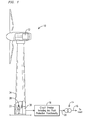
- FIG. 1 is a schematic representation of a wind turbine 10 that can benefit from an apparatus embodying aspects of the present invention.
- Wind turbine 10 includes a wind turbine generator 12 configured to generate an alternating current (AC) power output.
- a transformer 14, such as a local step-up transformer, has a high-voltage side 16 coupled to a load, such as a collector system 60 in a wind park 50 ( FIG. 3 ).
- a circuit breaker 18 is adapted to selectively provide arc flash protection functionality in connection with wind turbine 10. In one non-limiting embodiment, this protection may be realized by way of reducing the amount of arc flash energy available to the wind turbine.
- circuit breaker 18 is arranged to provide circuit interruption between wind turbine generator 12 and a low-voltage side 20 of transformer 14 upon detection of a fault condition.
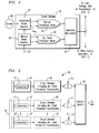
- circuit breaker 18 comprises a normal protection mode 22 and an arc flash protection mode 24.
- a respective one of the modes may be automatically set so that an operating mechanism 26 of circuit breaker 18 can perform the circuit interruption in accordance with the protection functionality of the set mode.
- the arc flash protection mode 24 may be configured so that circuit breaker 18 may interrupt a short circuit current over a relatively quicker time interval.
- the arc flash protection mode 24 may comprise a clearing time of approximately half-cycle or less.
- the clearing time associated with the normal protection mode 22 in one non-limiting example may range from approximately eight cycles to approximately ten cycles.
- the arc flash energy is a function of the product of the square of the fault current and the arc duration (i.e., time)
- appropriately reducing the arc duration can decrease the arc flash energy to a level that may be safely accommodated with PPE.
- At least one sensor 30 is coupled to an automated mode selector 32 of circuit breaker 18 for automatically setting in response to the sensed condition the arc flash protection mode or the normal protection mode. That is, either the arc flash protection mode or the normal protection mode may be automatically selected during appropriate situations or conditions.
- Sensor 30 may be configured to sense whether AC power output is being generated by wind turbine generator 20 so that, for example, when wind turbine generator 12 is not generating power, the arc flash protection mode 24 is automatically set. Conversely, once wind turbine generator 12 resumes power generation, circuit breaker 18 can automatically revert to the normal protection mode 22.
- Sensor 30 may be configured to sense a condition of a door 33 that provides access into a tower 34 of wind turbine 10. Sensor 30 may configured to sense a condition indicative of access or proximity to a serviceable electric panel 36 of wind turbine 10.
- Sensor 30 may be configured to sense a presence of a human being 38 in a predefined area (e.g., a boundary area) of wind turbine 10.
- sensor 30 may comprise an electrical sensor, an optical sensor, an ultrasound sensor, a motion sensor, and a combination of two or more of such sensors.
- circuit breaker 18 may further include a manual mode selector 40 adapted to override operation of the automated mode selector 32.
- a manual mode selector 40 adapted to override operation of the automated mode selector 32.
- one or more key switches (schematically represented by arrow 42) may be used to override automated mode selector 32 and manually set the arc flash protection mode or the normal protection mode.
- FIG. 3 is a schematic representation of a plurality of wind turbines connected to a collector system 60 where each of such wind turbines can individually benefit from respective apparatuses embodying aspects of the present invention.
- FIG. 3 may represent a portion of a wind park 50, where wind turbine 10 includes arc flash protection functionality provided by way of circuit breaker 18 interconnected between generator 12 and the low-voltage side of transformer 14, as disclosed above in the context of FIGs. 1 and 2 .
- wind turbine 10 in combination with further wind turbines 61 comprise a plurality of wind turbines connected to feed collector system 60, which in turn may be connected to the grid.
- the further wind turbines 61 may be arranged to include respective circuit breakers 18', 18" adapted to selectively provide individualized arc flash protection in connection with the further wind turbines 61.
- circuit breaker 18' is interconnected between the low-voltage side of transformer 14' and the wind turbine generator of an associated wind turbine from further wind turbines 61.
Landscapes
- Engineering & Computer Science (AREA)
- Power Engineering (AREA)
- Life Sciences & Earth Sciences (AREA)
- Sustainable Development (AREA)
- Sustainable Energy (AREA)
- Chemical & Material Sciences (AREA)
- Combustion & Propulsion (AREA)
- Mechanical Engineering (AREA)
- General Engineering & Computer Science (AREA)
- Wind Motors (AREA)
- Control Of Eletrric Generators (AREA)
Abstract
Description
- The invention relates generally to wind turbines and, more particularly, to an apparatus including a circuit breaker adapted to selectively provide arc flash protection in connection with a wind turbine.
- Wind turbines use naturally-available wind energy to generate electricity in an environmentally-friendly manner. Utility grade wind turbines (e.g., wind turbines designed to provide electrical power to a utility grid) can develop substantially high-levels of arc flash hazard when connected to the grid. An arc flash hazard, as presently defined by a standard titled ""Electrical Safety in the Workplace (NFPA 70E), refers to "a dangerous condition associated with the possible release of energy caused by an electrical arc".
- The electrical arc can generate substantially high temperatures and create a pressure wave, not unlike an explosion, causing metal particles, equipment parts and other loose items to be expelled from the electrical arc flash area in addition to the expulsion of hot, ionized gases. If a human being is present in the vicinity of such arc flash hazard, bodily injury, or worse can result. Applicable governmental regulations, as well as applicable electric codes, specify warnings, markings, and personnel protection equipment (PPE), such as clothing, goggles, gloves, etc., that are designed to protect personnel working in such arc flash areas. However, for electrical equipment interconnected to the grid, arc flash levels can exceed multiple times the maximum level of protection afforded by such PPE. In view of the foregoing considerations, a cost-effective and reliable solution for arc flash protection in the context of wind turbines is needed. Disclosed embodiments are believed to successfully address at least such needs.
- The invention is explained in the following description in view of the drawings that show:
-
FIG. 1 is a schematic representation of a wind turbine that can benefit from an apparatus embodying aspects of the present invention. -
FIG. 2 is a schematic representation of a disclosed circuit breaker including an arc flash protection mode and a normal protection mode. -
FIG. 3 is a schematic representation of plurality of wind turbines connected to a collector system, where such wind turbines can individually benefit from respective apparatuses embodying aspects of the present invention. - The present inventors have cleverly recognized that certain known techniques for ameliorating arc flash hazards in connection with wind turbines can be substantially burdensome and/or costly. For example, removing a circuit connection to the power grid by disconnecting a step-up transformer that connects a given wind turbine to the grid can entail various disadvantages. Firstly, disconnecting such a step-up transformer may be substantially burdensome since such a transformer is generally only disconnectable on its high-voltage side (as may involve in one example application a voltage level of approximately 34.5 kV), which in turn requires the involvement of a technician appropriately qualified to service electrical equipment carrying such voltage levels. Secondly, the disconnection of such a transformer may also entail disconnection of the collector system associated with the given turbine (in one example application the collector system may comprise a feeding string of up to 15 wind turbines). That is, the entire string of wind turbines may be temporarily taken out of service, which can detrimentally affect the power generation capability of the wind park.
- In view of such a recognition, the present inventors propose an innovative apparatus including a cost-effective and reliable device, such as a circuit breaker adapted to selectively provide arc flash protection in connection with a given wind turbine so that personnel can --with reduced exposure to arc flash energy -- perform servicing operations, as may involve servicing of electric panels and/or electric equipment that may be disposed inside the relatively tight spacing of the tower of the wind turbine.
- In the following detailed description, various specific details are set forth in order to provide a thorough understanding of such embodiments. However, those skilled in the art will understand that embodiments of the present invention may be practiced without these specific details, that the present invention is not limited to the depicted embodiments, and that the present invention may be practiced in a variety of alternative embodiments. In other instances, methods, procedures, and components, which would be well-understood by one skilled in the art have not been described in detail to avoid unnecessary and burdensome explanation.
- Furthermore, various operations may be described as multiple discrete steps performed in a manner that is helpful for understanding embodiments of the present invention. However, the order of description should not be construed as to imply that these operations need be performed in the order they are presented, nor that they are even order dependent unless otherwise so described. Moreover, repeated usage of the phrase "in one embodiment" does not necessarily refer to the same embodiment, although it may. Lastly, the terms "comprising", "including", "having", and the like, as used in the present application, are intended to be synonymous unless otherwise indicated.
-
FIG. 1 is a schematic representation of awind turbine 10 that can benefit from an apparatus embodying aspects of the present invention.Wind turbine 10 includes awind turbine generator 12 configured to generate an alternating current (AC) power output. Atransformer 14, such as a local step-up transformer, has a high-voltage side 16 coupled to a load, such as acollector system 60 in a wind park 50 (FIG. 3 ). As will be described in greater detail below, acircuit breaker 18 is adapted to selectively provide arc flash protection functionality in connection withwind turbine 10. In one non-limiting embodiment, this protection may be realized by way of reducing the amount of arc flash energy available to the wind turbine. - In one non-limiting embodiment,
circuit breaker 18 is arranged to provide circuit interruption betweenwind turbine generator 12 and a low-voltage side 20 oftransformer 14 upon detection of a fault condition. In one non-limiting embodiment, as illustrated inFIG. 2 ,circuit breaker 18 comprises anormal protection mode 22 and an arcflash protection mode 24. For example, in response to a sensed condition, a respective one of the modes may be automatically set so that anoperating mechanism 26 ofcircuit breaker 18 can perform the circuit interruption in accordance with the protection functionality of the set mode. - In one non-limiting embodiment, the arc
flash protection mode 24 may be configured so thatcircuit breaker 18 may interrupt a short circuit current over a relatively quicker time interval. In one non-limiting example, the arcflash protection mode 24 may comprise a clearing time of approximately half-cycle or less. By way of comparison, the clearing time associated with thenormal protection mode 22 in one non-limiting example may range from approximately eight cycles to approximately ten cycles. As will be appreciated by those skilled in the art, since at a given distance the arc flash energy is a function of the product of the square of the fault current and the arc duration (i.e., time), appropriately reducing the arc duration can decrease the arc flash energy to a level that may be safely accommodated with PPE. - In one non-limiting embodiment, at least one
sensor 30 is coupled to anautomated mode selector 32 ofcircuit breaker 18 for automatically setting in response to the sensed condition the arc flash protection mode or the normal protection mode. That is, either the arc flash protection mode or the normal protection mode may be automatically selected during appropriate situations or conditions. - The description below provides various non-limiting examples of sensing arrangements and/or sensing modalities that may be employed individually or in combination to sense various non-limiting example conditions for automatically setting the arc flash protection mode or the normal protection mode.
Sensor 30 may be configured to sense whether AC power output is being generated bywind turbine generator 20 so that, for example, whenwind turbine generator 12 is not generating power, the arcflash protection mode 24 is automatically set. Conversely, oncewind turbine generator 12 resumes power generation,circuit breaker 18 can automatically revert to thenormal protection mode 22.Sensor 30 may be configured to sense a condition of adoor 33 that provides access into atower 34 ofwind turbine 10.Sensor 30 may configured to sense a condition indicative of access or proximity to a serviceableelectric panel 36 ofwind turbine 10.Sensor 30 may be configured to sense a presence of ahuman being 38 in a predefined area (e.g., a boundary area) ofwind turbine 10. Without limitation,sensor 30 may comprise an electrical sensor, an optical sensor, an ultrasound sensor, a motion sensor, and a combination of two or more of such sensors. - In one non-limiting embodiment,
circuit breaker 18 may further include amanual mode selector 40 adapted to override operation of theautomated mode selector 32. For example, one or more key switches (schematically represented by arrow 42) may be used to overrideautomated mode selector 32 and manually set the arc flash protection mode or the normal protection mode. For example, one can override the automated mode selector so that the arcflash protection mode 24 is disengaged althoughsensor 30 may not be sensing power generation bywind turbine generator 12. -
FIG. 3 is a schematic representation of a plurality of wind turbines connected to acollector system 60 where each of such wind turbines can individually benefit from respective apparatuses embodying aspects of the present invention.FIG. 3 may represent a portion of awind park 50, wherewind turbine 10 includes arc flash protection functionality provided by way ofcircuit breaker 18 interconnected betweengenerator 12 and the low-voltage side oftransformer 14, as disclosed above in the context ofFIGs. 1 and2 . - In this non-limiting embodiment,
wind turbine 10 in combination with further wind turbines 61 (schematically represented by bracket 61) comprise a plurality of wind turbines connected tofeed collector system 60, which in turn may be connected to the grid. In this non-limiting embodiment, thefurther wind turbines 61 may be arranged to includerespective circuit breakers 18', 18" adapted to selectively provide individualized arc flash protection in connection with thefurther wind turbines 61. For example, circuit breaker 18' is interconnected between the low-voltage side of transformer 14' and the wind turbine generator of an associated wind turbine fromfurther wind turbines 61. That is, the protective functionality ofrespective circuit breakers 18', 18" with respect to its associated wind turbine is practically identical to the protection functionality provided bycircuit breaker 18 with respect towind turbine 10, and such functionality will not be repeated to spare the reader from pedantic and unnecessary disclosure. This arrangement is advantageous since any respective one of the wind turbines that feedscollector system 60 may be serviced with a relatively higher degree of protection -- as may involve servicing of electric panels and/or electric equipment-- when the arc flash protection mode is set in its respective circuit breaker without having to disconnect the entire string of wind turbines connected to the collector system. - While various embodiments of the present invention have been shown and described herein, it will be apparent that such embodiments are provided by way of example only. Numerous variations, changes and substitutions may be made without departing from the invention herein. Accordingly, it is intended that the invention be limited only by the spirit and scope of the appended claims.
Claims (15)
- An apparatus comprising:a wind turbine comprising a wind turbine generator configured to generate an alternating current (AC) power output;a transformer having a high-voltage side coupled to a load; anda circuit breaker adapted to selectively reduce arc flash energy available to the wind turbine, the circuit breaker arranged to provide circuit interruption between the wind turbine generator and a low-voltage side of the transformer upon detection of a fault condition, the circuit breaker having an arc flash protection mode and a normal protection mode, wherein, in response to a sensed condition, a respective one of the modes is automatically set so that the circuit breaker can perform the circuit interruption in accordance with a protection functionality of the set mode.
- The apparatus of claim 1, further comprising at least one sensor coupled to an automated mode selector of the circuit breaker for automatically setting in response to the sensed condition the arc flash protection mode or the normal protection mode.
- The apparatus according to any of the preceding claims, further comprising a manual mode selector adapted to override the automated mode selector.
- The apparatus of claim 3, wherein the manual mode selector comprises a key switch.
- The apparatus according to any of the preceding claims, wherein the at least one sensor comprises a sensor selected from the group consisting of an electrical sensor, an optical sensor, an ultrasound sensor, a motion sensor, and a combination of two or more of said sensors.
- The apparatus according to any of the preceding claims, wherein the load comprises a collector system fed by the wind turbine and further wind turbines.
- The apparatus of claim 6, wherein the further wind turbines comprise respective circuit breakers adapted to selectively provide individualized arc flash protection in connection with the further wind turbines.
- An apparatus comprising:a transformer having a high-voltage side coupled to a load;a circuit breaker arranged to provide circuit interruption between a wind turbine generator of a wind turbine and a low-voltage side of the transformer upon detection of a fault condition, the circuit breaker comprising an arc flash protection mode and a normal protection mode, wherein, in response to a sensed condition, a respective one of the modes is automatically set so that the circuit breaker can perform the circuit interruption in accordance with a protection functionality of the set mode; andat least one sensor coupled to a mode selector of the circuit breaker for automatically setting in response to the sensed condition the arc flash protection mode or the normal protection mode.
- The apparatus according to any of the preceding claims, wherein the at least one sensor is configured to sense whether AC power output is being generated by the wind turbine generator.
- The apparatus according to any of the preceding claims, wherein the at least one sensor is configured to sense a condition of a door that provides access into a tower of the wind turbine.
- The apparatus according to any of the preceding claims, wherein the at least one sensor is configured to sense a condition indicative of access or proximity to a serviceable electric panel of the wind turbine.
- The apparatus of any of the claims 8 to 12, wherein the at least one sensor is configured to sense a presence of a human being in a predefined area of the wind turbine.
- The apparatus of any of the claims 8 to 12, further comprising a manual mode selector adapted to override the mode sector for automatically setting the arc flash protection module or the normal protection module.
- The apparatus of claim 13, wherein the manual selector comprises a key switch.
- An apparatus comprising:a transformer associated with a respective one of a plurality of wind turbines, the transformer having a high-voltage side coupled to a collector system fed by the plurality of wind turbines;a circuit breaker adapted to selectively reduce arc flash energy available to the respective one wind turbine, the circuit breaker arranged to provide circuit interruption between a wind turbine generator of the respective one wind turbine and a low-voltage side of the transformer upon detection of a fault condition, the circuit breaker comprising an arc flash protection mode and a normal protection mode, wherein, in response to a sensed condition, a respective one of the modes is automatically set so that the circuit breaker can perform the circuit interruption in accordance with a protection functionality of the set mode; andat least one sensor coupled to an automated mode selector of the circuit breaker for automatically setting in response to the sensed condition the arc flash protection mode or the normal protection mode,wherein further ones of the plurality of wind turbines that feed the collector system comprise respective circuit breakers adapted to selectively and individually reduce arc flash energy available to the further ones of the plurality of wind turbines.
Applications Claiming Priority (1)
| Application Number | Priority Date | Filing Date | Title |
|---|---|---|---|
| US14/284,664 US9318283B2 (en) | 2014-05-22 | 2014-05-22 | Apparatus including a circuit breaker adapted to selectively provide arc flash protection in connection with a wind turbine |
Publications (3)
| Publication Number | Publication Date |
|---|---|
| EP2947738A2 true EP2947738A2 (en) | 2015-11-25 |
| EP2947738A3 EP2947738A3 (en) | 2016-03-16 |
| EP2947738B1 EP2947738B1 (en) | 2021-10-06 |
Family
ID=53298131
Family Applications (1)
| Application Number | Title | Priority Date | Filing Date |
|---|---|---|---|
| EP15168284.6A Active EP2947738B1 (en) | 2014-05-22 | 2015-05-20 | Apparatus including a circuit breaker adapted to selectively provide arc flash protection in connection with a wind turbine |
Country Status (5)
| Country | Link |
|---|---|
| US (1) | US9318283B2 (en) |
| EP (1) | EP2947738B1 (en) |
| CN (1) | CN105089933B (en) |
| DK (1) | DK2947738T3 (en) |
| ES (1) | ES2895938T3 (en) |
Families Citing this family (1)
| Publication number | Priority date | Publication date | Assignee | Title |
|---|---|---|---|---|
| US20180112648A1 (en) * | 2016-10-20 | 2018-04-26 | James Bond | Hybrid wind turbine for power output in low and zero wind conditions |
Family Cites Families (9)
| Publication number | Priority date | Publication date | Assignee | Title |
|---|---|---|---|---|
| US7203040B2 (en) | 2004-03-31 | 2007-04-10 | Gaton Corporation | Method and circuit breaker for reducing arc flash during maintenance in a low voltage power circuit |
| US7292422B2 (en) | 2004-11-29 | 2007-11-06 | Siemens Energy & Automation, Inc. | Occupancy-based circuit breaker control |
| US7646575B2 (en) | 2006-03-09 | 2010-01-12 | Utility Relay Co., Ltd. | Manually-controlled arc flash energy reduction system and method for circuit breaker trip units |
| US20080142486A1 (en) * | 2006-12-19 | 2008-06-19 | Nataniel Barbosa Vicente | Circuit breaker with adjustable arc-flash protection and wireless sensor and method of use |
| AT504659B1 (en) | 2006-12-22 | 2008-07-15 | Moeller Gebaeudeautomation Gmb | ELECTRICAL INSTALLATION ARRANGEMENT AND METHOD FOR OPERATING AN ELECTRICAL INSTALLATION ARRANGEMENT |
| US7929260B2 (en) * | 2007-03-30 | 2011-04-19 | General Electric Company | Arc flash elimination system, apparatus, and method |
| US7944068B2 (en) * | 2008-06-30 | 2011-05-17 | General Electric Company | Optimizing converter protection for wind turbine generators |
| US8351171B2 (en) | 2008-10-14 | 2013-01-08 | Siemens Industry, Inc. | Integrated automatic selection of maintenance mode in electronic tripping systems to minimize arc fault energy |
| US8797720B2 (en) | 2011-09-13 | 2014-08-05 | Utility Relay Company | Manually-controlled arc flash energy reduction system and method for circuit breaker trip units |
-
2014
- 2014-05-22 US US14/284,664 patent/US9318283B2/en active Active
-
2015
- 2015-05-20 EP EP15168284.6A patent/EP2947738B1/en active Active
- 2015-05-20 ES ES15168284T patent/ES2895938T3/en active Active
- 2015-05-20 DK DK15168284.6T patent/DK2947738T3/en active
- 2015-05-22 CN CN201510264331.0A patent/CN105089933B/en active Active
Non-Patent Citations (1)
| Title |
|---|
| None |
Also Published As
| Publication number | Publication date |
|---|---|
| ES2895938T3 (en) | 2022-02-23 |
| CN105089933B (en) | 2019-02-19 |
| DK2947738T3 (en) | 2021-12-06 |
| EP2947738A3 (en) | 2016-03-16 |
| EP2947738B1 (en) | 2021-10-06 |
| US20150340180A1 (en) | 2015-11-26 |
| CN105089933A (en) | 2015-11-25 |
| US9318283B2 (en) | 2016-04-19 |
Similar Documents
| Publication | Publication Date | Title |
|---|---|---|
| JP5830802B2 (en) | Method and photovoltaic installation for limiting the generator voltage of photovoltaic installations in hazardous situations | |
| US9416773B2 (en) | Power generation and distribution system for a wind turbine | |
| CN102484419A (en) | A method and a device for overvoltage protection, and an electric system with such a device | |
| US7292422B2 (en) | Occupancy-based circuit breaker control | |
| CN104377582B (en) | Box-type substation | |
| EP2675033A1 (en) | Method and systems for discharging energy from an electrical fault | |
| WO2008113742A3 (en) | Compact secondary substation comprising an arcing fault protection system, a method for arcing fault protection in a compact secondary substation, and a control unit for performing the method | |
| US9318283B2 (en) | Apparatus including a circuit breaker adapted to selectively provide arc flash protection in connection with a wind turbine | |
| AU2017362445B2 (en) | Power electronics with isolating fuse | |
| EP3271986B1 (en) | Shorting device for a rectifier | |
| KR102071209B1 (en) | Power converting apparatus for supplying dc power for dc distributing line | |
| EP3271984B1 (en) | Excitation system with a protection device against an arc fault | |
| CN104022498A (en) | Device for arc discharging protecting in switch cabinet | |
| CN203801845U (en) | Comprehensive protection insulating shoe | |
| KR101198281B1 (en) | Apparatus for detecting earth leakage for preventing malfunctioning according to noise of leakage breaker | |
| CN202633151U (en) | Breaker | |
| CN107658733A (en) | Novel rectifying switch cubicle | |
| CN206406762U (en) | New energy vehicle high-tension electricity quick cutting device | |
| Rush et al. | Battery Energy Storage Systems Safety: Critical Steps for the Maturing Storage Market | |
| Babb | Use of Specific Purpose Fuses for Mitigation of ARC Flash Hazard | |
| US20100308776A1 (en) | Battery charger | |
| CN201671858U (en) | Safe solar photovoltaic ventilator | |
| CN205680954U (en) | A kind of household type explosion-proof electrical distribution box | |
| JP2016167917A (en) | Inverter for system interconnection | |
| CN204290378U (en) | Electric capacity quick discharging circuit |
Legal Events
| Date | Code | Title | Description |
|---|---|---|---|
| PUAI | Public reference made under article 153(3) epc to a published international application that has entered the european phase |
Free format text: ORIGINAL CODE: 0009012 |
|
| AK | Designated contracting states |
Kind code of ref document: A2 Designated state(s): AL AT BE BG CH CY CZ DE DK EE ES FI FR GB GR HR HU IE IS IT LI LT LU LV MC MK MT NL NO PL PT RO RS SE SI SK SM TR |
|
| AX | Request for extension of the european patent |
Extension state: BA ME |
|
| PUAL | Search report despatched |
Free format text: ORIGINAL CODE: 0009013 |
|
| AK | Designated contracting states |
Kind code of ref document: A3 Designated state(s): AL AT BE BG CH CY CZ DE DK EE ES FI FR GB GR HR HU IE IS IT LI LT LU LV MC MK MT NL NO PL PT RO RS SE SI SK SM TR |
|
| AX | Request for extension of the european patent |
Extension state: BA ME |
|
| RIC1 | Information provided on ipc code assigned before grant |
Ipc: F03D 9/00 20160101ALI20160209BHEP Ipc: H02H 3/00 20060101ALI20160209BHEP Ipc: H02H 3/093 20060101ALI20160209BHEP Ipc: F03D 11/00 00000000ALI20160209BHEP Ipc: H02H 1/00 20060101AFI20160209BHEP |
|
| 17P | Request for examination filed |
Effective date: 20160706 |
|
| RBV | Designated contracting states (corrected) |
Designated state(s): AL AT BE BG CH CY CZ DE DK EE ES FI FR GB GR HR HU IE IS IT LI LT LU LV MC MK MT NL NO PL PT RO RS SE SI SK SM TR |
|
| RAP1 | Party data changed (applicant data changed or rights of an application transferred) |
Owner name: SIEMENS AKTIENGESELLSCHAFT |
|
| STAA | Information on the status of an ep patent application or granted ep patent |
Free format text: STATUS: EXAMINATION IS IN PROGRESS |
|
| 17Q | First examination report despatched |
Effective date: 20180813 |
|
| RAP1 | Party data changed (applicant data changed or rights of an application transferred) |
Owner name: SIEMENS GAMESA RENEWABLE ENERGY A/S |
|
| RIC1 | Information provided on ipc code assigned before grant |
Ipc: H02H 1/00 20060101AFI20210329BHEP Ipc: H02H 3/093 20060101ALI20210329BHEP Ipc: F03D 9/00 20160101ALI20210329BHEP Ipc: F03D 9/25 20160101ALI20210329BHEP Ipc: H02H 3/00 20060101ALI20210329BHEP Ipc: F03D 80/00 20160101ALI20210329BHEP |
|
| GRAP | Despatch of communication of intention to grant a patent |
Free format text: ORIGINAL CODE: EPIDOSNIGR1 |
|
| STAA | Information on the status of an ep patent application or granted ep patent |
Free format text: STATUS: GRANT OF PATENT IS INTENDED |
|
| INTG | Intention to grant announced |
Effective date: 20210514 |
|
| GRAS | Grant fee paid |
Free format text: ORIGINAL CODE: EPIDOSNIGR3 |
|
| GRAA | (expected) grant |
Free format text: ORIGINAL CODE: 0009210 |
|
| STAA | Information on the status of an ep patent application or granted ep patent |
Free format text: STATUS: THE PATENT HAS BEEN GRANTED |
|
| AK | Designated contracting states |
Kind code of ref document: B1 Designated state(s): AL AT BE BG CH CY CZ DE DK EE ES FI FR GB GR HR HU IE IS IT LI LT LU LV MC MK MT NL NO PL PT RO RS SE SI SK SM TR |
|
| REG | Reference to a national code |
Ref country code: GB Ref legal event code: FG4D |
|
| REG | Reference to a national code |
Ref country code: CH Ref legal event code: EP Ref country code: AT Ref legal event code: REF Ref document number: 1437026 Country of ref document: AT Kind code of ref document: T Effective date: 20211015 |
|
| REG | Reference to a national code |
Ref country code: IE Ref legal event code: FG4D |
|
| REG | Reference to a national code |
Ref country code: DE Ref legal event code: R096 Ref document number: 602015073849 Country of ref document: DE |
|
| REG | Reference to a national code |
Ref country code: DK Ref legal event code: T3 Effective date: 20211201 |
|
| REG | Reference to a national code |
Ref country code: LT Ref legal event code: MG9D |
|
| REG | Reference to a national code |
Ref country code: NL Ref legal event code: MP Effective date: 20211006 |
|
| REG | Reference to a national code |
Ref country code: ES Ref legal event code: FG2A Ref document number: 2895938 Country of ref document: ES Kind code of ref document: T3 Effective date: 20220223 |
|
| REG | Reference to a national code |
Ref country code: AT Ref legal event code: MK05 Ref document number: 1437026 Country of ref document: AT Kind code of ref document: T Effective date: 20211006 |
|
| PG25 | Lapsed in a contracting state [announced via postgrant information from national office to epo] |
Ref country code: RS Free format text: LAPSE BECAUSE OF FAILURE TO SUBMIT A TRANSLATION OF THE DESCRIPTION OR TO PAY THE FEE WITHIN THE PRESCRIBED TIME-LIMIT Effective date: 20211006 Ref country code: LT Free format text: LAPSE BECAUSE OF FAILURE TO SUBMIT A TRANSLATION OF THE DESCRIPTION OR TO PAY THE FEE WITHIN THE PRESCRIBED TIME-LIMIT Effective date: 20211006 Ref country code: FI Free format text: LAPSE BECAUSE OF FAILURE TO SUBMIT A TRANSLATION OF THE DESCRIPTION OR TO PAY THE FEE WITHIN THE PRESCRIBED TIME-LIMIT Effective date: 20211006 Ref country code: BG Free format text: LAPSE BECAUSE OF FAILURE TO SUBMIT A TRANSLATION OF THE DESCRIPTION OR TO PAY THE FEE WITHIN THE PRESCRIBED TIME-LIMIT Effective date: 20220106 Ref country code: AT Free format text: LAPSE BECAUSE OF FAILURE TO SUBMIT A TRANSLATION OF THE DESCRIPTION OR TO PAY THE FEE WITHIN THE PRESCRIBED TIME-LIMIT Effective date: 20211006 |
|
| PG25 | Lapsed in a contracting state [announced via postgrant information from national office to epo] |
Ref country code: IS Free format text: LAPSE BECAUSE OF FAILURE TO SUBMIT A TRANSLATION OF THE DESCRIPTION OR TO PAY THE FEE WITHIN THE PRESCRIBED TIME-LIMIT Effective date: 20220206 Ref country code: SE Free format text: LAPSE BECAUSE OF FAILURE TO SUBMIT A TRANSLATION OF THE DESCRIPTION OR TO PAY THE FEE WITHIN THE PRESCRIBED TIME-LIMIT Effective date: 20211006 Ref country code: PT Free format text: LAPSE BECAUSE OF FAILURE TO SUBMIT A TRANSLATION OF THE DESCRIPTION OR TO PAY THE FEE WITHIN THE PRESCRIBED TIME-LIMIT Effective date: 20220207 Ref country code: PL Free format text: LAPSE BECAUSE OF FAILURE TO SUBMIT A TRANSLATION OF THE DESCRIPTION OR TO PAY THE FEE WITHIN THE PRESCRIBED TIME-LIMIT Effective date: 20211006 Ref country code: NO Free format text: LAPSE BECAUSE OF FAILURE TO SUBMIT A TRANSLATION OF THE DESCRIPTION OR TO PAY THE FEE WITHIN THE PRESCRIBED TIME-LIMIT Effective date: 20220106 Ref country code: NL Free format text: LAPSE BECAUSE OF FAILURE TO SUBMIT A TRANSLATION OF THE DESCRIPTION OR TO PAY THE FEE WITHIN THE PRESCRIBED TIME-LIMIT Effective date: 20211006 Ref country code: LV Free format text: LAPSE BECAUSE OF FAILURE TO SUBMIT A TRANSLATION OF THE DESCRIPTION OR TO PAY THE FEE WITHIN THE PRESCRIBED TIME-LIMIT Effective date: 20211006 Ref country code: HR Free format text: LAPSE BECAUSE OF FAILURE TO SUBMIT A TRANSLATION OF THE DESCRIPTION OR TO PAY THE FEE WITHIN THE PRESCRIBED TIME-LIMIT Effective date: 20211006 Ref country code: GR Free format text: LAPSE BECAUSE OF FAILURE TO SUBMIT A TRANSLATION OF THE DESCRIPTION OR TO PAY THE FEE WITHIN THE PRESCRIBED TIME-LIMIT Effective date: 20220107 |
|
| REG | Reference to a national code |
Ref country code: DE Ref legal event code: R097 Ref document number: 602015073849 Country of ref document: DE |
|
| PG25 | Lapsed in a contracting state [announced via postgrant information from national office to epo] |
Ref country code: SM Free format text: LAPSE BECAUSE OF FAILURE TO SUBMIT A TRANSLATION OF THE DESCRIPTION OR TO PAY THE FEE WITHIN THE PRESCRIBED TIME-LIMIT Effective date: 20211006 Ref country code: SK Free format text: LAPSE BECAUSE OF FAILURE TO SUBMIT A TRANSLATION OF THE DESCRIPTION OR TO PAY THE FEE WITHIN THE PRESCRIBED TIME-LIMIT Effective date: 20211006 Ref country code: RO Free format text: LAPSE BECAUSE OF FAILURE TO SUBMIT A TRANSLATION OF THE DESCRIPTION OR TO PAY THE FEE WITHIN THE PRESCRIBED TIME-LIMIT Effective date: 20211006 Ref country code: EE Free format text: LAPSE BECAUSE OF FAILURE TO SUBMIT A TRANSLATION OF THE DESCRIPTION OR TO PAY THE FEE WITHIN THE PRESCRIBED TIME-LIMIT Effective date: 20211006 Ref country code: CZ Free format text: LAPSE BECAUSE OF FAILURE TO SUBMIT A TRANSLATION OF THE DESCRIPTION OR TO PAY THE FEE WITHIN THE PRESCRIBED TIME-LIMIT Effective date: 20211006 |
|
| REG | Reference to a national code |
Ref country code: DE Ref legal event code: R082 Ref document number: 602015073849 Country of ref document: DE Representative=s name: SAUTHOFF, KARSTEN, DIPL.-ING. UNIV., DE |
|
| PLBE | No opposition filed within time limit |
Free format text: ORIGINAL CODE: 0009261 |
|
| STAA | Information on the status of an ep patent application or granted ep patent |
Free format text: STATUS: NO OPPOSITION FILED WITHIN TIME LIMIT |
|
| 26N | No opposition filed |
Effective date: 20220707 |
|
| PG25 | Lapsed in a contracting state [announced via postgrant information from national office to epo] |
Ref country code: AL Free format text: LAPSE BECAUSE OF FAILURE TO SUBMIT A TRANSLATION OF THE DESCRIPTION OR TO PAY THE FEE WITHIN THE PRESCRIBED TIME-LIMIT Effective date: 20211006 |
|
| PG25 | Lapsed in a contracting state [announced via postgrant information from national office to epo] |
Ref country code: SI Free format text: LAPSE BECAUSE OF FAILURE TO SUBMIT A TRANSLATION OF THE DESCRIPTION OR TO PAY THE FEE WITHIN THE PRESCRIBED TIME-LIMIT Effective date: 20211006 |
|
| REG | Reference to a national code |
Ref country code: CH Ref legal event code: PL |
|
| REG | Reference to a national code |
Ref country code: BE Ref legal event code: MM Effective date: 20220531 |
|
| PG25 | Lapsed in a contracting state [announced via postgrant information from national office to epo] |
Ref country code: MC Free format text: LAPSE BECAUSE OF FAILURE TO SUBMIT A TRANSLATION OF THE DESCRIPTION OR TO PAY THE FEE WITHIN THE PRESCRIBED TIME-LIMIT Effective date: 20211006 Ref country code: LU Free format text: LAPSE BECAUSE OF NON-PAYMENT OF DUE FEES Effective date: 20220520 Ref country code: LI Free format text: LAPSE BECAUSE OF NON-PAYMENT OF DUE FEES Effective date: 20220531 Ref country code: CH Free format text: LAPSE BECAUSE OF NON-PAYMENT OF DUE FEES Effective date: 20220531 |
|
| PG25 | Lapsed in a contracting state [announced via postgrant information from national office to epo] |
Ref country code: IE Free format text: LAPSE BECAUSE OF NON-PAYMENT OF DUE FEES Effective date: 20220520 |
|
| PG25 | Lapsed in a contracting state [announced via postgrant information from national office to epo] |
Ref country code: IT Free format text: LAPSE BECAUSE OF FAILURE TO SUBMIT A TRANSLATION OF THE DESCRIPTION OR TO PAY THE FEE WITHIN THE PRESCRIBED TIME-LIMIT Effective date: 20211006 Ref country code: BE Free format text: LAPSE BECAUSE OF NON-PAYMENT OF DUE FEES Effective date: 20220531 |
|
| PG25 | Lapsed in a contracting state [announced via postgrant information from national office to epo] |
Ref country code: HU Free format text: LAPSE BECAUSE OF FAILURE TO SUBMIT A TRANSLATION OF THE DESCRIPTION OR TO PAY THE FEE WITHIN THE PRESCRIBED TIME-LIMIT; INVALID AB INITIO Effective date: 20150520 |
|
| PG25 | Lapsed in a contracting state [announced via postgrant information from national office to epo] |
Ref country code: MK Free format text: LAPSE BECAUSE OF FAILURE TO SUBMIT A TRANSLATION OF THE DESCRIPTION OR TO PAY THE FEE WITHIN THE PRESCRIBED TIME-LIMIT Effective date: 20211006 Ref country code: CY Free format text: LAPSE BECAUSE OF FAILURE TO SUBMIT A TRANSLATION OF THE DESCRIPTION OR TO PAY THE FEE WITHIN THE PRESCRIBED TIME-LIMIT Effective date: 20211006 |
|
| PG25 | Lapsed in a contracting state [announced via postgrant information from national office to epo] |
Ref country code: TR Free format text: LAPSE BECAUSE OF FAILURE TO SUBMIT A TRANSLATION OF THE DESCRIPTION OR TO PAY THE FEE WITHIN THE PRESCRIBED TIME-LIMIT Effective date: 20211006 |
|
| PG25 | Lapsed in a contracting state [announced via postgrant information from national office to epo] |
Ref country code: MT Free format text: LAPSE BECAUSE OF FAILURE TO SUBMIT A TRANSLATION OF THE DESCRIPTION OR TO PAY THE FEE WITHIN THE PRESCRIBED TIME-LIMIT Effective date: 20211006 |
|
| PGFP | Annual fee paid to national office [announced via postgrant information from national office to epo] |
Ref country code: DE Payment date: 20250528 Year of fee payment: 11 |
|
| PGFP | Annual fee paid to national office [announced via postgrant information from national office to epo] |
Ref country code: GB Payment date: 20250520 Year of fee payment: 11 Ref country code: DK Payment date: 20250526 Year of fee payment: 11 Ref country code: ES Payment date: 20250611 Year of fee payment: 11 |
|
| PGFP | Annual fee paid to national office [announced via postgrant information from national office to epo] |
Ref country code: FR Payment date: 20250526 Year of fee payment: 11 |