EP2947625A1 - Method and apparatus for selection of reliable points for 3D modeling - Google Patents
Method and apparatus for selection of reliable points for 3D modeling Download PDFInfo
- Publication number
- EP2947625A1 EP2947625A1 EP14305747.9A EP14305747A EP2947625A1 EP 2947625 A1 EP2947625 A1 EP 2947625A1 EP 14305747 A EP14305747 A EP 14305747A EP 2947625 A1 EP2947625 A1 EP 2947625A1
- Authority
- EP
- European Patent Office
- Prior art keywords
- depth
- displacement
- confidence maps
- maps
- spatio
- Prior art date
- Legal status (The legal status is an assumption and is not a legal conclusion. Google has not performed a legal analysis and makes no representation as to the accuracy of the status listed.)
- Withdrawn
Links
Images




Classifications
-
- G—PHYSICS
- G06—COMPUTING OR CALCULATING; COUNTING
- G06T—IMAGE DATA PROCESSING OR GENERATION, IN GENERAL
- G06T7/00—Image analysis
- G06T7/20—Analysis of motion
- G06T7/269—Analysis of motion using gradient-based methods
-
- G—PHYSICS
- G06—COMPUTING OR CALCULATING; COUNTING
- G06T—IMAGE DATA PROCESSING OR GENERATION, IN GENERAL
- G06T7/00—Image analysis
- G06T7/50—Depth or shape recovery
- G06T7/55—Depth or shape recovery from multiple images
-
- G—PHYSICS
- G06—COMPUTING OR CALCULATING; COUNTING
- G06T—IMAGE DATA PROCESSING OR GENERATION, IN GENERAL
- G06T7/00—Image analysis
- G06T7/50—Depth or shape recovery
- G06T7/55—Depth or shape recovery from multiple images
- G06T7/579—Depth or shape recovery from multiple images from motion
-
- G—PHYSICS
- G06—COMPUTING OR CALCULATING; COUNTING
- G06T—IMAGE DATA PROCESSING OR GENERATION, IN GENERAL
- G06T7/00—Image analysis
- G06T7/50—Depth or shape recovery
- G06T7/55—Depth or shape recovery from multiple images
- G06T7/593—Depth or shape recovery from multiple images from stereo images
-
- G—PHYSICS
- G06—COMPUTING OR CALCULATING; COUNTING
- G06T—IMAGE DATA PROCESSING OR GENERATION, IN GENERAL
- G06T2207/00—Indexing scheme for image analysis or image enhancement
- G06T2207/10—Image acquisition modality
- G06T2207/10016—Video; Image sequence
-
- G—PHYSICS
- G06—COMPUTING OR CALCULATING; COUNTING
- G06T—IMAGE DATA PROCESSING OR GENERATION, IN GENERAL
- G06T2207/00—Indexing scheme for image analysis or image enhancement
- G06T2207/10—Image acquisition modality
- G06T2207/10028—Range image; Depth image; 3D point clouds
-
- G—PHYSICS
- G06—COMPUTING OR CALCULATING; COUNTING
- G06T—IMAGE DATA PROCESSING OR GENERATION, IN GENERAL
- G06T2207/00—Indexing scheme for image analysis or image enhancement
- G06T2207/30—Subject of image; Context of image processing
- G06T2207/30196—Human being; Person
- G06T2207/30201—Face
Definitions
- the present disclosure generally relates to a method and apparatus for selection of reliable points for 3D (3-Dimensional) modeling.
- 3D modeling is used in modeling of objects or scenes, for example.
- the modeling of objects or scenes may be used for facial capture or tracking, facial animation, and the like.
- the selection of dynamic mesh vertices from a set of 3D points determines the accuracy of the dynamic 3D model.
- a method may include generating depth confidence maps and displacement confidence maps from dynamic image data including depth information; computing spatio-temporal reliability criteria for depth and displacement confidences, for pixels of a scene object in each of sequential frames of the dynamic image data, based on the depth confidence maps and the displacement confidence maps; and selecting a set of 3D points for forming a 3D model, having a spatio-temporal reliability criterion higher than a threshold for the spatio-temporal reliability criteria.
- an apparatus may include a generating unit configured to generate depth confidence maps and displacement confidence maps from dynamic image data including depth information; a computing unit configured to compute spatio-temporal reliability criteria for depth and displacement confidences, for pixels of a scene object in each of sequential frames of the dynamic image data, based on the depth confidence maps and the displacement confidence maps; and a selection unit configured to select a set of 3D points for forming a 3D model, having a spatio-temporal reliability criterion higher than a threshold for the spatio-temporal reliability criteria.
- a computer-readable storage medium having stored therein a program which, when executed by a computer, may cause the computer to perform a process that includes generating depth confidence maps and displacement confidence maps from dynamic image data including depth information; computing spatio-temporal reliability criteria for depth and displacement confidences, for pixels of a scene object in each of sequential frames of the dynamic image data, based on the depth confidence maps and the displacement confidence maps; and selecting a set of 3D points for forming a 3D model, having a spatio-temporal reliability criterion higher than a threshold for the spatio-temporal reliability criteria.
- FIG. 1 is a block diagram illustrating an example of the apparatus according to an embodiment of the present invention.
- a 3D modeling apparatus 10 illustrated in FIG. 1 includes an image capturing unit 11, a depth generating unit 12, an optical flow estimating unit 13, and a dynamic 3D mesh modeling unit 14.
- the image capturing unit 11 may be provided as an external apparatus that is externally connectable to the 3D modeling apparatus 10.
- the image capturing unit 11 captures a real-world object or scene, and outputs dynamic image data including depth information.
- the dynamic image data may include a plurality of sequential color frames together with corresponding depth information for each frame.
- the depth information indicates a distance of surfaces of scene objects (that is, objects within the scene) from a viewpoint of the image capturing unit 11.
- the image capturing unit 11 may be formed by a stereo video camera, a ToF (Time-of-Flight) camera, a structured light 3D scanning device, or any suitable known means or unit capable of capturing a dynamic image together with the depth information.
- the dynamic image data output from the image capturing unit 11 may be used to extract texture of scene objects, to estimate surface normals of scene objects observed under different lighting conditions by photometric stereo, to obtain illumination map or albedo of scene objects, or the like.
- the depth generating unit 12 generates depth maps and depth confidence maps for each frame, based on the dynamic image data and the depth information output from the image capturing unit 11.
- the depth confidence maps are supplied to the dynamic 3D mesh modeling unit 14.
- the optical flow estimating unit 13 estimates an optical flow of the scene object, and generates displacement maps and displacement confidence maps for each frame, based on the dynamic image data output from the image capturing unit 11. As is well known in the art, the optical flow describes the motion of a point on the scene object by a vector.
- the displacement confidence maps are supplied to the dynamic 3D mesh modeling unit 14.
- the depth generating unit 12 and the optical flow estimating unit 13 may form a single generating unit to generate the depth confidence map and the displacement confidence map.
- the dynamic 3D mesh modeling unit 14 includes a point selection unit 141 and a consistent connectivity determination unit 142.
- the point selection unit 141 makes a reliable selection of 3D points, that is, dynamic mesh vertices, from a set of 3D points for dynamic 3D modeling of the scene object with a high accuracy and a high resolution, based on the depth confidence maps and the displacement confidence maps.
- the point selection unit 141 will be described later in more detail in conjunction with FIG. 2 .
- the consistent connectivity determination unit 142 determines a consistent connectivity of the 3D points selected by the point selection unit 141, in order to add the consistent connectivity to the selected dynamic mesh vertices forming a dynamic 3D mesh model.
- the consistent connectivity of one 3D point in a given frame indicates that a corresponding 3D point exists in a previous frame which occurred before the given frame in time and in a next frame which occurs after the given frame in time.
- the consistent connectivity By adding the consistent connectivity to the selected dynamic mesh vertices forming the dynamic 3D mesh model, it is possible to define the mesh vertices to which each mesh vertex is connected and thus define faces or polygons (for example, triangles, quadrangles, or the like), in order to form the raw set of mesh vertices (or 3D points) into the dynamic 3D mesh model.
- faces or polygons for example, triangles, quadrangles, or the like
- the output of the consistent connectivity determination unit 142 may be used to build the dynamic 3D mesh model in which the occurrence of each mesh is consistent amongst successive frames.
- the consistent connectivity is required in a case in which the meshes are to be processed to provide temporally smooth visual effects, for example. If the meshes were not consistent amongst the successive frames, temporal artifacts would occur.
- the 3D dynamic meshes of the dynamic 3D mesh model, added with the consistent connectivity may be used at a latter stage of the dynamic 3D mesh modeling unit 14, for statistical modeling, for example.
- Each of the depth generating unit 12, the optical flow estimating unit 13, and the dynamic 3D mesh modeling unit 14 may be formed by dedicated hardware. Alternatively, the functions of at least one of the depth generating unit 12, the optical flow estimating unit 13, and the dynamic 3D mesh modeling unit 14 may be performed by a computer, as will be described later in conjunction with FIGs. 6 and 7 .
- FIG. 2 is a block diagram illustrating a part of the 3D modeling apparatus illustrated in FIG. 1 .
- a spatio-temporal reliability computing unit 1411 and a best score selection unit 1412 form the point selection unit 141 illustrated in FIG. 1 .
- the spatio-temporal reliability computing unit 1411 receives the depth confidence maps from the depth generating unit 12, the displacement maps and the displacement confidence maps from the optical flow estimating unit 13, and a spatio-temporal tradeoff weight.
- the best score selection unit 1412 receives an output of the spatio-temporal reliability computation unit 1411, and a user-specified threshold.
- the depth maps may be inter-view disparity maps.
- the depth generating unit 12 may function as a depth estimating unit.
- An inter-view disparity d, in pixels can be represented by the following formula (1), where b denotes an inter-axial distance (in meters) of a camera rig, f denotes a focal length (in pixels) of the stereo video camera forming the image capturing unit 11, and z denotes a depth (in meters) of the scene object.
- the inter-axial distance of the camera rig may correspond to a distance between optical axes of the stereo video camera mounted on the camera rig.
- d b ⁇ f / z
- the inter-view disparity maps can be delivered in a format represented by a scaling operation dedicated to transmission, for example.
- D ⁇ 1 2 n - 1 d - d min / d max - d min
- the depth maps can also be delivered by a ToF camera or a structured light 3D scanning device, such as the PrimeSense (registered trademark) Kinect (registered trademark) device, forming the image capturing unit 11.
- a normalized depth D2 can be expressed as a function of the depth z of the scene object and be represented by the following formula (3), where A and B denote calibration parameters, represented by the formulas (4) and (5), that convert the depth, in meters, into an integer than fits on 10 bits, for example.
- the depth generating unit 12 may function as a depth measuring unit.
- z near and z far denote a near DoF (Depth of Field) and a far DoF, respectively.
- a ⁇ -361 and B ⁇ 1095 for example.
- the depth confidence maps may be computed during the depth estimation process.
- An example of a depth confidence may be expressed as a function of energy minimized, by a reliability criterion R z represented by the following formula (6), for example, where min 1 E and min 3 E denote a lowest energy and third lowest energy, respectively.
- R z min 3 ⁇ E - min 1 ⁇ E / min 3 ⁇ E
- reliability criteria other than the reliability criterion R z described above may be used for the depth confidence maps.
- Examples of the reliability criteria other than the reliability criterion R z include confidence values proposed in Xiaoyan Hu, et al., "A Quantitative Evaluation of Confidence Measures for Stereo Vision", IEEE Transactions on Pattern Analysis And Machine Intelligence, 2012 , for example.
- FIGs. 3A, 3B, and 3C are diagrams illustrating examples of a color frame, a corresponding estimated depth map, and a corresponding estimated confidence map.
- FIG. 3B the darker the tone of the image, the closer the scene object is to the stereo video camera.
- FIG. 3C the darker the tone of the image, the higher the depth confidence is in the depth confidence map.
- the depth confidence maps may be generated together with the depth information, or computed during a depth measuring process.
- the depth confidence maps may be generated based on a signal indicating a light intensity, from the ToF camera forming the image capturing unit 11.
- the PrimeSense (registered trademark) Kinect (registered trademark) device forming the image capturing unit 11 binary confidence maps can be straightforwardly derived from depth maps holes, as illustrated in FIGs. 4A and 4B , for example.
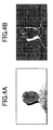
- FIGs. 4A and 4B are diagrams illustrating examples of a measured depth map and a corresponding measured confidence map.
- FIG. 4A the darker the tone of the image, the closer the scene object is to the stereo video camera, and black areas represent holes.
- the darker the tone of the image the higher the depth confidence is in the depth confidence map.
- a dense optical flow (du, dv) is required for each of the sequential color frames in order to determine trajectories of pixels along which reliability criteria are temporally integrated.
- An inter-frame optical flow estimation may be similar to the inter-view disparity estimation described above.
- the displacement maps may be inter-frame disparity maps.
- R m for a displacement confidence of the displacement confidence map can be computed during the optical flow estimation, in a manner similar to computing the reliability criterion R z for the depth confidence of the depth confidence map during the depth estimation process.
- FIG. 5 is a diagram illustrating a process of determining pixel trajectories from backward and forward optical flows.
- circular marks denote pixels, and considering a given pixel p i in a given frame, a trajectory of this pixel p i along the plurality of sequential color frames (hereinafter also referred to as "a sequence of the frames") is denoted by T i .
- T i a trajectory of this pixel p i along the plurality of sequential color frames
- a dotted line arrow pointing to the left indicates a backward optical flow
- a dotted line arrow pointing to the right indicates a forward optical flow
- a bold arrow pointing to the left indicates a backward sub-trajectory T i - of a backward part of the trajectory T i
- a bold arrow pointing to the right indicates a forward sub-trajectory T i + of a forward part of the trajectory T i .
- Bilinear interpolation may be performed in order to determine displacements at sub-pixel locations in FIG. 5 .
- an average spatio-temporal reliability (or confidence) m i can be computed from the following formula (7), where ⁇ denotes the user-specified spatio-temporal tradeoff weight satisfying a relationship 0 ⁇ ⁇ ⁇ 1.
- a bilinear interpolation may also be performed in order to determine the reliability criteria R m and R z at the sub-pixel locations.
- a spatio-temporal reliability (or confidence) variance var i along the trajectory T i may be computed.
- the spatial-temporal reliability computing unit 1411 illustrated in FIG. 2 computes a score S of each pixel p i from the following formula (8), where ⁇ denotes a shape of the scene object in a set of key-frames selected by a user.
- the score S indicates a value that depends on the spatio-temporal reliability criterion and the user-specified spatio-temporal tradeoff weight ⁇ , and in this example, the score S indicates the value that depends on the average spatio-temporal reliability m i and the spatio-temporal reliability variance var i .
- the set of key-frames may include an arbitrary frame at an intermediate part (for example, middle) of the sequence of the frame, or first and last frames of the sequence of the frames, or particular frames of the sequence of the frames to circumvent potential partial occlusions, for example.
- S m i - var i i ⁇ ⁇
- the best score selection unit 1412 illustrated in FIG. 2 receives the scores S output from the spatio-temporal reliability computing unit 1411, and selects a best score S b for each pixel p i in the set of the key-frames, based on the user-specified threshold, in order to output a set of reliable 3D points with the best scores S b higher than a score indicated by the user-specified threshold.
- the set of reliable 3D points output from the best score selection unit 1412 is supplied to the consistent connectivity determination unit 142 illustrated in FIG. 1 .
- FIG. 6 is block diagram illustrating an example of a hardware configuration of a computer.
- a computer 60 illustrated in FIG. 6 includes a processor 61, such as a CPU (Central Processing Unit), a storage unit 62, an input device 63, and an output device 64, and an interface unit 65 which are connected by a bus 66.
- processor 61 such as a CPU (Central Processing Unit)
- storage unit 62 such as a hard disk drive
- input device 63 such as a keyboard
- 64 output device
- an interface unit 65 which are connected by a bus 66.
- constituent elements of the computer 60 may be connected by a connection other than a bus connection using the bus 66.
- the processor 61 controls operations of the computer 60.
- the storage unit 62 stores at least one program to be executed by the processor 61, and various data, including the dynamic image data received from the image capturing unit 11, parameters used by computations performed by the processor 61, intermediate data of computations performed by the processor 61, the 3D dynamic meshes of the dynamic 3D mesh model, added with the consistent connectivity, to be used for statistical modeling, for example, or the like.
- the storage unit 62 may be formed by any suitable storage or means capable of storing the program, data, or the like in a computer-readable manner.
- Examples of the storage unit 62 include non-transitory computer-readable storage media such as semiconductor memory devices, and magnetic, optical, or magneto-optical recording media loaded into a read and write unit.
- the program causes the processor 61 to perform a process of at least one of the depth generating unit 12, the optical flow estimating unit 13, and the dynamic 3D mesh modeling unit 14, in order to cause the computer 60 to perform the function of at least one of the depth generating unit 12, the optical flow estimating unit 13, and the dynamic 3D mesh modeling unit 14 illustrated in FIG. 1 .
- the program may cause software modules of the computer 60 to function as the 3D modeling apparatus 10, in response to the dynamic image data including the depth information, received from the image capturing unit 11.
- the input device 63 may be formed by a keyboard or the like for use by the user to input commands, to make user's selections, to specify thresholds and parameters, or the like with respect to the computer 60.
- the output device 64 may be formed by a display device to display messages or the like to the user, outputs of the computer such as the dynamic 3D mesh model, or the like.
- the input device 63 and the output device 64 may be formed integrally by a touchscreen panel, for example.
- the interface unit 65 provides an interface between the computer 60 and an external apparatus, such as the image capture unit 11 illustrated in FIG. 1 .
- the interface unit 65 may be communicable with the external apparatus via cable or wireless communication.
- FIG. 7 is a flow chart illustrating an example of a process performed by the apparatus.
- the processor 61 forming the computer 60 illustrated in FIG. 6 executes the program stored in the storage unit 62 to perform the processes of the depth generating unit 12, the optical flow estimating unit 13, and the dynamic 3D mesh modeling unit 14 illustrated in FIG. 1 .
- step S1 the processor 61, in step S1, generates the depth confidence maps from the image data including the depth information received from the image capturing unit 11 during a depth estimation process that generates the depth maps, and generates the displacement confidence maps from the dynamic image data including the depth information received from the image capturing unit 11 during an optical flow estimation process that generates the displacement confidence maps.
- the process of step S1 may correspond to the processes of the depth generating unit 12 and the optical flow estimating unit 13 illustrated in FIG. 2 .
- the processor 61 in step S2, computes the spatio-temporal reliability criteria for depth and displacement confidences, for pixels of a scene object in each of sequential frames of the dynamic image data, based on the depth confidence maps and the displacement confidence maps.
- the processor 61 in step S3 selects a set of 3D points for forming a 3D model, having a spatio-temporal reliability criterion higher than a threshold for the spatio-temporal reliability criteria. The process ends after step S3.
- the processor 61 may compute scores S that depend on the spatio-temporal reliability criteria for the depth and the displacement (or motion) confidences, for pixels of the scene object in each of the sequential color frames of the dynamic image data, based on the depth confidence maps, the displacement confidence maps, and the spatio-temporal tradeoff weight ⁇ , and output the score with the pixels.
- the processor 61 may select the best score S b for each pixel p i in the set of the key-frames, from amongst the scores S output in step S2, based on a user-specified threshold for the scores, in order to output a set of reliable 3D points with the best score S b higher than a score indicated by the user-specified threshold for the scores.
- the process of step S2 may correspond to the process of the spatio-temporal reliability computing unit 1411 illustrated in FIG. 2
- the process of step S3 may correspond to the process of the best score selection unit 1412 illustrated in FIG. 2 .
- the depth generating unit 12 generates the depth maps because the depth generating unit 12 may generate the depth confidence maps during the process that generates the depth maps, and the optical flow estimating unit 13 generates the displacement maps because the optical flow estimating unit 13 may generate the displacement confidence maps during the process that generates the displacement maps.
- the depth generating unit 12 may omit generating the depth maps and the optical flow estimating unit 13 may omit generating the displacement maps in a case in which the depth maps and the displacement maps are unnecessary for the process to be performed in the 3D modeling apparatus 10, or the depth maps and the displacement maps are unnecessary for generating the depth confidence maps and the displacement confidence maps.
- the depth maps and the depth confidence maps may be generated by any suitable known methods other than those described above.
- the displacement maps and the displacement confidence maps may be generated by any suitable known methods other than those described above.
- the embodiment described above may be applied to dynamic 3D mesh modeling in visual effects (VFX) of cinema production, consumers solutions (for example, face editing or enhancement application software on mobile terminals), or the like.
- the embodiment may also be suited for GPGPU (General-Purpose computing on Graphics Processing Units) programming, parallelized with grids corresponding to Q-points.
- GPGPU General-Purpose computing on Graphics Processing Units
- the 3D modeling of the object or scene can be achieved with a high accuracy and a high resolution, when compared to conventional methods.
Landscapes
- Engineering & Computer Science (AREA)
- Computer Vision & Pattern Recognition (AREA)
- Physics & Mathematics (AREA)
- General Physics & Mathematics (AREA)
- Theoretical Computer Science (AREA)
- Multimedia (AREA)
- Image Processing (AREA)
- Image Analysis (AREA)
Abstract
A method includes generating depth confidence maps and displacement confidence maps from dynamic image data including depth information, computing spatio-temporal reliability criteria for depth and displacement confidences, for pixels of a scene object in each of sequential frames of the dynamic image data, based on the depth confidence maps and the displacement confidence maps, and selecting a set of 3D points for forming a 3D model, having a spatio-temporal reliability criterion higher than a threshold for the spatio-temporal reliability criteria.
Description
- The present disclosure generally relates to a method and apparatus for selection of reliable points for 3D (3-Dimensional) modeling.
- 3D modeling is used in modeling of objects or scenes, for example. The modeling of objects or scenes may be used for facial capture or tracking, facial animation, and the like. When generating a dynamic 3D model based on a real-world object or scene that is captured by a camera, for example, the selection of dynamic mesh vertices from a set of 3D points determines the accuracy of the dynamic 3D model.
- As an example, Levi Valgaerts et al., "Lightweight Binocular Facial Performance Capture under Uncontrolled Lighting", ACM Transactions on Graphics (Proc. SIGGRAPH ASIA, Vol. 31(6), 187:1-187:11, 2012 proposes tracking points at each frame of consecutive frames with respect to a template mesh that is initialized at a first frame, as described in conjunction with
Figure 2 of Levi Valgaerts et al. However, a template-based approach lacks robustness in that it is difficult to capture the real-world object or scene by the camera so that the orientation of the object or scene in the captured image (or the camera's field of view) matches the orientation of the object or scene in the template. - On the other hand, Hao Li, et al., "Realtime Facial Animation with On-the-fly Correctives", ACM Transactions on Graphics, Proceedings of the 40th ACM SIGGGRAPH Conference and Exhibition 2013, 07/2013, and "http://msdn.microsoft.com/en-us/library/jj130970.aspx #ID4EDLAE" (SDK link), for example, propose relying on sparse feature points for coarser initializations, as described in conjunction with
Figure 1 of Hao Li, et al. and as described in conjunction withFigure 2 and AUs (Animation Units) of the SDK link. However, feature-point based approaches do not provide a sufficiently large number of points for enabling accurate 3D modeling, and it is difficult to generate a high-resolution 3D model. - According to an aspect of the present disclosure, a method may include generating depth confidence maps and displacement confidence maps from dynamic image data including depth information; computing spatio-temporal reliability criteria for depth and displacement confidences, for pixels of a scene object in each of sequential frames of the dynamic image data, based on the depth confidence maps and the displacement confidence maps; and selecting a set of 3D points for forming a 3D model, having a spatio-temporal reliability criterion higher than a threshold for the spatio-temporal reliability criteria.
- According to another aspect of the present disclosure, an apparatus may include a generating unit configured to generate depth confidence maps and displacement confidence maps from dynamic image data including depth information; a computing unit configured to compute spatio-temporal reliability criteria for depth and displacement confidences, for pixels of a scene object in each of sequential frames of the dynamic image data, based on the depth confidence maps and the displacement confidence maps; and a selection unit configured to select a set of 3D points for forming a 3D model, having a spatio-temporal reliability criterion higher than a threshold for the spatio-temporal reliability criteria.
- According to still another aspect of the present disclosure, a computer-readable storage medium having stored therein a program which, when executed by a computer, may cause the computer to perform a process that includes generating depth confidence maps and displacement confidence maps from dynamic image data including depth information; computing spatio-temporal reliability criteria for depth and displacement confidences, for pixels of a scene object in each of sequential frames of the dynamic image data, based on the depth confidence maps and the displacement confidence maps; and selecting a set of 3D points for forming a 3D model, having a spatio-temporal reliability criterion higher than a threshold for the spatio-temporal reliability criteria.
- The object and advantages of the present disclosure will be realized and attained by means of the elements and combinations particularly pointed out in the claims.
- It is to be understood that both the foregoing general description and the following detailed description are exemplary and explanatory and are not restrictive of the invention, as claimed.
-
-
FIG. 1 is a block diagram illustrating an example of an apparatus according to an embodiment of the present invention; -
FIG. 2 is a block diagram illustrating a part of the apparatus illustrated inFIG. 1 ; -
FIGs. 3A, 3B, and 3C are diagrams illustrating examples of a color frame, a corresponding estimated depth map, and a corresponding estimation confidence map; -
FIGs. 4A and 4B are diagrams illustrating examples of a measured depth map and a corresponding confidence map; -
FIG. 5 is a diagram illustrating a process of determining pixel trajectories from backward and forward optical flows; -
FIG. 6 is block diagram illustrating an example of a hardware configuration of a computer; and -
FIG. 7 is a flow chart illustrating an example of a process performed by the apparatus. - Embodiments of the present invention will be described with reference to the accompanying drawings.
- A description will now be given of a method, an apparatus, and a computer-readable storage medium, in each embodiment according to the present invention.
-
FIG. 1 is a block diagram illustrating an example of the apparatus according to an embodiment of the present invention. A3D modeling apparatus 10 illustrated inFIG. 1 includes animage capturing unit 11, adepth generating unit 12, an opticalflow estimating unit 13, and a dynamic 3Dmesh modeling unit 14. However, theimage capturing unit 11 may be provided as an external apparatus that is externally connectable to the3D modeling apparatus 10. - The
image capturing unit 11 captures a real-world object or scene, and outputs dynamic image data including depth information. The dynamic image data may include a plurality of sequential color frames together with corresponding depth information for each frame. The depth information indicates a distance of surfaces of scene objects (that is, objects within the scene) from a viewpoint of theimage capturing unit 11. Theimage capturing unit 11 may be formed by a stereo video camera, a ToF (Time-of-Flight) camera, a structuredlight 3D scanning device, or any suitable known means or unit capable of capturing a dynamic image together with the depth information. - For example, the dynamic image data output from the
image capturing unit 11 may be used to extract texture of scene objects, to estimate surface normals of scene objects observed under different lighting conditions by photometric stereo, to obtain illumination map or albedo of scene objects, or the like. - The
depth generating unit 12 generates depth maps and depth confidence maps for each frame, based on the dynamic image data and the depth information output from theimage capturing unit 11. The depth confidence maps are supplied to the dynamic 3Dmesh modeling unit 14. - The optical
flow estimating unit 13 estimates an optical flow of the scene object, and generates displacement maps and displacement confidence maps for each frame, based on the dynamic image data output from theimage capturing unit 11. As is well known in the art, the optical flow describes the motion of a point on the scene object by a vector. The displacement confidence maps are supplied to the dynamic 3Dmesh modeling unit 14. - The
depth generating unit 12 and the opticalflow estimating unit 13 may form a single generating unit to generate the depth confidence map and the displacement confidence map. - The dynamic 3D
mesh modeling unit 14 includes apoint selection unit 141 and a consistentconnectivity determination unit 142. Thepoint selection unit 141 makes a reliable selection of 3D points, that is, dynamic mesh vertices, from a set of 3D points for dynamic 3D modeling of the scene object with a high accuracy and a high resolution, based on the depth confidence maps and the displacement confidence maps. Thepoint selection unit 141 will be described later in more detail in conjunction withFIG. 2 . - The consistent
connectivity determination unit 142 determines a consistent connectivity of the 3D points selected by thepoint selection unit 141, in order to add the consistent connectivity to the selected dynamic mesh vertices forming a dynamic 3D mesh model. The consistent connectivity of one 3D point in a given frame indicates that a corresponding 3D point exists in a previous frame which occurred before the given frame in time and in a next frame which occurs after the given frame in time. By adding the consistent connectivity to the selected dynamic mesh vertices forming the dynamic 3D mesh model, it is possible to define the mesh vertices to which each mesh vertex is connected and thus define faces or polygons (for example, triangles, quadrangles, or the like), in order to form the raw set of mesh vertices (or 3D points) into the dynamic 3D mesh model. - Hence, the output of the consistent
connectivity determination unit 142 may be used to build the dynamic 3D mesh model in which the occurrence of each mesh is consistent amongst successive frames. The consistent connectivity is required in a case in which the meshes are to be processed to provide temporally smooth visual effects, for example. If the meshes were not consistent amongst the successive frames, temporal artifacts would occur. The 3D dynamic meshes of the dynamic 3D mesh model, added with the consistent connectivity, may be used at a latter stage of the dynamic 3Dmesh modeling unit 14, for statistical modeling, for example. - Each of the
depth generating unit 12, the opticalflow estimating unit 13, and the dynamic 3Dmesh modeling unit 14 may be formed by dedicated hardware. Alternatively, the functions of at least one of thedepth generating unit 12, the opticalflow estimating unit 13, and the dynamic 3Dmesh modeling unit 14 may be performed by a computer, as will be described later in conjunction withFIGs. 6 and7 . -
FIG. 2 is a block diagram illustrating a part of the 3D modeling apparatus illustrated inFIG. 1 . InFIG. 2 , a spatio-temporalreliability computing unit 1411 and a bestscore selection unit 1412 form thepoint selection unit 141 illustrated inFIG. 1 . The spatio-temporalreliability computing unit 1411 receives the depth confidence maps from thedepth generating unit 12, the displacement maps and the displacement confidence maps from the opticalflow estimating unit 13, and a spatio-temporal tradeoff weight. The bestscore selection unit 1412 receives an output of the spatio-temporalreliability computation unit 1411, and a user-specified threshold. - Next, a description will be given of the depth maps and the depth confidence maps generated by the
depth generating unit 12. - The depth maps may be inter-view disparity maps. In this case, the
depth generating unit 12 may function as a depth estimating unit. An inter-view disparity d, in pixels, can be represented by the following formula (1), where b denotes an inter-axial distance (in meters) of a camera rig, f denotes a focal length (in pixels) of the stereo video camera forming theimage capturing unit 11, and z denotes a depth (in meters) of the scene object. The inter-axial distance of the camera rig may correspond to a distance between optical axes of the stereo video camera mounted on the camera rig.
- The inter-view disparity maps can be delivered in a format represented by a scaling operation dedicated to transmission, for example. In the case of a depth estimation process, a normalized disparity D1 on n bits being targeted can be represented by the following formula (2), where n = 8, 12, or 16, for example, dmin denotes a minimum disparity, and dmax denotes a maximum disparity. As an example, D1 = 0 when d = dmin, and D1 = 2n - 1 when d = dmax. When n = 8, for example, D1 = 2n - 1 = 255.

- The depth maps can also be delivered by a ToF camera or a
structured light 3D scanning device, such as the PrimeSense (registered trademark) Kinect (registered trademark) device, forming theimage capturing unit 11. In other words, a normalized depth D2 can be expressed as a function of the depth z of the scene object and be represented by the following formula (3), where A and B denote calibration parameters, represented by the formulas (4) and (5), that convert the depth, in meters, into an integer than fits on 10 bits, for example. In this case, thedepth generating unit 12 may function as a depth measuring unit. In the formulas (4) and (5), znear and zfar denote a near DoF (Depth of Field) and a far DoF, respectively.


- In the formulas (3) through (5) described above, A ≈ -361 and B ≈ 1095, for example. A value beyond the measurable range of the normalized depth D2 (D2 = 2047 (0x7FF)) may be reserved for holes for which no depth is available.
- Next, a description will be given of the depth confidence maps. In the case in which the
depth generating unit 12 functions as the depth estimating unit that estimates the inter-view disparity, the depth confidence maps may be computed during the depth estimation process. An example of a depth confidence may be expressed as a function of energy minimized, by a reliability criterion Rz represented by the following formula (6), for example, where min1E and min3E denote a lowest energy and third lowest energy, respectively.
- Of course, reliability criteria other than the reliability criterion Rz described above may be used for the depth confidence maps. Examples of the reliability criteria other than the reliability criterion Rz include confidence values proposed in Xiaoyan Hu, et al., "A Quantitative Evaluation of Confidence Measures for Stereo Vision", IEEE Transactions on Pattern Analysis And Machine Intelligence, 2012, for example.
-
FIGs. 3A, 3B, and 3C are diagrams illustrating examples of a color frame, a corresponding estimated depth map, and a corresponding estimated confidence map. InFIG. 3B , the darker the tone of the image, the closer the scene object is to the stereo video camera. InFIG. 3C , the darker the tone of the image, the higher the depth confidence is in the depth confidence map. - On the other hand, in the case in which the
depth generating unit 12 functions as the depth measuring unit that measures the depth, the depth confidence maps may be generated together with the depth information, or computed during a depth measuring process. For example, the depth confidence maps may be generated based on a signal indicating a light intensity, from the ToF camera forming theimage capturing unit 11. Thus, in the case of the PrimeSense (registered trademark) Kinect (registered trademark) device forming theimage capturing unit 11, binary confidence maps can be straightforwardly derived from depth maps holes, as illustrated inFIGs. 4A and 4B , for example.FIGs. 4A and 4B are diagrams illustrating examples of a measured depth map and a corresponding measured confidence map. InFIG. 4A , the darker the tone of the image, the closer the scene object is to the stereo video camera, and black areas represent holes. InFIG. 4B , the darker the tone of the image, the higher the depth confidence is in the depth confidence map. - Next, a description will be given of the displacement maps and the displacement confidence maps.
- When pixel coordinates within a frame of the sequential color frames are denoted by (u, v), a dense optical flow (du, dv) is required for each of the sequential color frames in order to determine trajectories of pixels along which reliability criteria are temporally integrated. An inter-frame optical flow estimation may be similar to the inter-view disparity estimation described above. Hence, the displacement maps may be inter-frame disparity maps.
- An example of the displacement reliability (or motion reliability) Rm for a displacement confidence of the displacement confidence map can be computed during the optical flow estimation, in a manner similar to computing the reliability criterion Rz for the depth confidence of the depth confidence map during the depth estimation process.
- Next, a description will be given of a spatio-temporal reliability criteria computed by the spatio-temporal
reliability computing unit 1411. In the following description, it is assumed for the sake of convenience that the reliability criteria Rz and Rm for the depth confidence and the displacement (or motion) confidence, respectively, are positive and normalized, such that the following relationships are satisfied.
-
FIG. 5 is a diagram illustrating a process of determining pixel trajectories from backward and forward optical flows. InFIG. 5 , circular marks denote pixels, and considering a given pixel pi in a given frame, a trajectory of this pixel pi along the plurality of sequential color frames (hereinafter also referred to as "a sequence of the frames") is denoted by Ti. In addition, inFIG. 5 , a dotted line arrow pointing to the left indicates a backward optical flow, a dotted line arrow pointing to the right indicates a forward optical flow, a bold arrow pointing to the left indicates a backward sub-trajectory Ti - of a backward part of the trajectory Ti, and a bold arrow pointing to the right indicates a forward sub-trajectory Ti + of a forward part of the trajectory Ti. Bilinear interpolation may be performed in order to determine displacements at sub-pixel locations inFIG. 5 . - For example, an average spatio-temporal reliability (or confidence) mi can be computed from the following formula (7), where α denotes the user-specified spatio-temporal tradeoff weight satisfying a relationship 0 ≤ α ≤ 1. A bilinear interpolation may also be performed in order to determine the reliability criteria Rm and Rz at the sub-pixel locations.

- In order to provide robustness to the depth and displacement (or motion) outliers, a spatio-temporal reliability (or confidence) variance vari along the trajectory Ti may be computed.
- The spatial-temporal
reliability computing unit 1411 illustrated inFIG. 2 computes a score S of each pixel pi from the following formula (8), where Ω denotes a shape of the scene object in a set of key-frames selected by a user. The score S indicates a value that depends on the spatio-temporal reliability criterion and the user-specified spatio-temporal tradeoff weight α, and in this example, the score S indicates the value that depends on the average spatio-temporal reliability mi and the spatio-temporal reliability variance vari. The set of key-frames may include an arbitrary frame at an intermediate part (for example, middle) of the sequence of the frame, or first and last frames of the sequence of the frames, or particular frames of the sequence of the frames to circumvent potential partial occlusions, for example.
- The best
score selection unit 1412 illustrated inFIG. 2 receives the scores S output from the spatio-temporalreliability computing unit 1411, and selects a best score Sb for each pixel pi in the set of the key-frames, based on the user-specified threshold, in order to output a set of reliable 3D points with the best scores Sb higher than a score indicated by the user-specified threshold. The set of reliable 3D points output from the bestscore selection unit 1412 is supplied to the consistentconnectivity determination unit 142 illustrated inFIG. 1 . -
FIG. 6 is block diagram illustrating an example of a hardware configuration of a computer. Acomputer 60 illustrated inFIG. 6 includes aprocessor 61, such as a CPU (Central Processing Unit), astorage unit 62, aninput device 63, and anoutput device 64, and aninterface unit 65 which are connected by abus 66. Of course, constituent elements of thecomputer 60 may be connected by a connection other than a bus connection using thebus 66. - The
processor 61 controls operations of thecomputer 60. Thestorage unit 62 stores at least one program to be executed by theprocessor 61, and various data, including the dynamic image data received from theimage capturing unit 11, parameters used by computations performed by theprocessor 61, intermediate data of computations performed by theprocessor 61, the 3D dynamic meshes of the dynamic 3D mesh model, added with the consistent connectivity, to be used for statistical modeling, for example, or the like. - The
storage unit 62 may be formed by any suitable storage or means capable of storing the program, data, or the like in a computer-readable manner. Examples of thestorage unit 62 include non-transitory computer-readable storage media such as semiconductor memory devices, and magnetic, optical, or magneto-optical recording media loaded into a read and write unit. - The program causes the
processor 61 to perform a process of at least one of thedepth generating unit 12, the opticalflow estimating unit 13, and the dynamic 3Dmesh modeling unit 14, in order to cause thecomputer 60 to perform the function of at least one of thedepth generating unit 12, the opticalflow estimating unit 13, and the dynamic 3Dmesh modeling unit 14 illustrated inFIG. 1 . In other words, the program may cause software modules of thecomputer 60 to function as the3D modeling apparatus 10, in response to the dynamic image data including the depth information, received from theimage capturing unit 11. - The
input device 63 may be formed by a keyboard or the like for use by the user to input commands, to make user's selections, to specify thresholds and parameters, or the like with respect to thecomputer 60. Theoutput device 64 may be formed by a display device to display messages or the like to the user, outputs of the computer such as the dynamic 3D mesh model, or the like. Theinput device 63 and theoutput device 64 may be formed integrally by a touchscreen panel, for example. Theinterface unit 65 provides an interface between thecomputer 60 and an external apparatus, such as theimage capture unit 11 illustrated inFIG. 1 . Theinterface unit 65 may be communicable with the external apparatus via cable or wireless communication. -
FIG. 7 is a flow chart illustrating an example of a process performed by the apparatus. In this example, it is assumed for the sake of convenience that theprocessor 61 forming thecomputer 60 illustrated inFIG. 6 executes the program stored in thestorage unit 62 to perform the processes of thedepth generating unit 12, the opticalflow estimating unit 13, and the dynamic 3Dmesh modeling unit 14 illustrated inFIG. 1 . - In
FIG. 7 , theprocessor 61, in step S1, generates the depth confidence maps from the image data including the depth information received from theimage capturing unit 11 during a depth estimation process that generates the depth maps, and generates the displacement confidence maps from the dynamic image data including the depth information received from theimage capturing unit 11 during an optical flow estimation process that generates the displacement confidence maps. The process of step S1 may correspond to the processes of thedepth generating unit 12 and the opticalflow estimating unit 13 illustrated inFIG. 2 . - The
processor 61, in step S2, computes the spatio-temporal reliability criteria for depth and displacement confidences, for pixels of a scene object in each of sequential frames of the dynamic image data, based on the depth confidence maps and the displacement confidence maps. - The
processor 61, in step S3 selects a set of 3D points for forming a 3D model, having a spatio-temporal reliability criterion higher than a threshold for the spatio-temporal reliability criteria. The process ends after step S3. - In step S2, the
processor 61 may compute scores S that depend on the spatio-temporal reliability criteria for the depth and the displacement (or motion) confidences, for pixels of the scene object in each of the sequential color frames of the dynamic image data, based on the depth confidence maps, the displacement confidence maps, and the spatio-temporal tradeoff weight α, and output the score with the pixels. In this case, in step S3, theprocessor 61 may select the best score Sb for each pixel pi in the set of the key-frames, from amongst the scores S output in step S2, based on a user-specified threshold for the scores, in order to output a set of reliable 3D points with the best score Sb higher than a score indicated by the user-specified threshold for the scores. In other words, the process of step S2 may correspond to the process of the spatio-temporalreliability computing unit 1411 illustrated inFIG. 2 , and the process of step S3 may correspond to the process of the bestscore selection unit 1412 illustrated inFIG. 2 . - In the embodiment described above, the
depth generating unit 12 generates the depth maps because thedepth generating unit 12 may generate the depth confidence maps during the process that generates the depth maps, and the opticalflow estimating unit 13 generates the displacement maps because the opticalflow estimating unit 13 may generate the displacement confidence maps during the process that generates the displacement maps. However, thedepth generating unit 12 may omit generating the depth maps and the opticalflow estimating unit 13 may omit generating the displacement maps in a case in which the depth maps and the displacement maps are unnecessary for the process to be performed in the3D modeling apparatus 10, or the depth maps and the displacement maps are unnecessary for generating the depth confidence maps and the displacement confidence maps. - The depth maps and the depth confidence maps may be generated by any suitable known methods other than those described above. Similarly, the displacement maps and the displacement confidence maps may be generated by any suitable known methods other than those described above.
- The embodiment described above may be applied to dynamic 3D mesh modeling in visual effects (VFX) of cinema production, consumers solutions (for example, face editing or enhancement application software on mobile terminals), or the like. The embodiment may also be suited for GPGPU (General-Purpose computing on Graphics Processing Units) programming, parallelized with grids corresponding to Q-points.
- According to the embodiment described above, the 3D modeling of the object or scene can be achieved with a high accuracy and a high resolution, when compared to conventional methods.
- All examples and conditional language recited herein are intended for pedagogical purposes to aid the reader in understanding the invention and the concepts contributed by the inventor to furthering the art, and are to be construed as being without limitation to such specifically recited examples and conditions, nor does the organization of such examples in the specification relate to a showing of the superiority and inferiority of the invention.
Claims (15)
- A method, including:generating (S1) depth confidence maps and displacement confidence maps from dynamic image data including depth information;computing (S2) spatio-temporal reliability criteria for depth and displacement confidences, for pixels of a scene object in each of sequential frames of the dynamic image data, based on the depth confidence maps and the displacement confidence maps; andselecting (S3) a set of 3D points for forming a 3D model, having a spatio-temporal reliability criterion higher than a threshold for the spatio-temporal reliability criteria.
- The method as claimed in claim 1,
wherein the computing (S2) computes scores that depend on the spatio-temporal reliability criteria for the depth and displacement confidences, for each pixel of the scene object in each of the sequential frames of the dynamic image data, based on the depth confidence maps, the displacement maps, the displacement confidence maps, and a spatio-temporal tradeoff weight, and outputs the scores with the pixels; and
wherein the selecting (S3) selects a best score for each pixel in a set of key-frames, from amongst the scores output by the computing, based on a user-specified threshold for the scores, in order to output a set of 3D points with the best score higher than a score indicated by the user-specified threshold for the scores. - The method as claimed in claim 1 or 2, wherein the generating (S1) includes:generating the depth confidence maps from inter-view disparity maps generated during a depth estimation process based on the depth information received from a stereo video camera, andgenerating the displacement confidence maps during an optical flow estimation process.
- The method as claimed in claim 1 or 2, wherein the generating (S1) includes:generating the depth confidence maps during a depth measuring process based on the depth information received from a ToF (Time-of-Flight) camera or a structured light 3D scanning device, andgenerating the displacement confidence maps during an optical flow estimation process.
- The method as claimed in any of claims 1 to 4, wherein the method further including:determining a consistent connectivity of the set of 3D points selected by the selecting, in order to add the consistent connectivity to dynamic mesh vertices forming a dynamic 3D mesh model.
- An apparatus, comprising:a generating unit (12, 13; 61) configured to generate depth confidence maps and displacement confidence maps from dynamic image data including depth information;a computing unit (14, 1411; 61) configured to compute spatio-temporal reliability criteria for depth and displacement confidences, for pixels of a scene object in each of sequential frames of the dynamic image data, based on the depth confidence maps and the displacement confidence maps; anda selection unit (14, 1412; 61) configured to select a set of 3D points for forming a 3D model, having a spatio-temporal reliability criterion higher than a threshold for the spatio-temporal reliability criteria.
- The apparatus as claimed in claim 6,
wherein the computing unit (14, 1411; 61) computes scores that depend on the spatio-temporal reliability criteria for the depth and displacement confidences, for each pixel of the scene object in each of the sequential frames of the dynamic image data, based on the depth confidence maps, the displacement maps, the displacement confidence maps, and a spatio-temporal tradeoff weight, and outputs the scores with the pixels; and
wherein the selecting unit (14, 1412; 61) selects a best score for each pixel in a set of key-frames, from amongst the scores output by the computing, based on a user-specified threshold for the scores, in order to output a set of 3D points with the best score higher than a score indicated by the user-specified threshold for the scores. - The apparatus as claimed in claim 6 or 7, wherein the generating unit (12, 13; 61) is configured to:generate the depth confidence maps from inter-view disparity maps generated during a depth estimation process based on the depth information received from a stereo video camera, andgenerate the displacement confidence maps during an optical flow estimation process.
- The apparatus as claimed in claim 6 or 7, wherein the generating unit (12, 13; 61) is configured to:generate the depth confidence maps during a depth measuring process based on the depth information received from a ToF (Time-of-Flight) camera or a structured light 3D scanning device, andgenerate the displacement confidence maps during an optical flow estimation process.
- The apparatus as claimed in any of claims 6 to 9, wherein the apparatus further comprising:a determination unit (14, 14; 61) configured to determine a consistent connectivity of the set of 3D points selected by the selecting, in order to add the consistent connectivity to dynamic mesh vertices forming a dynamic 3D mesh model.
- A computer-readable storage medium having stored therein a program which, when executed by a computer (61), causes the computer to perform a process including:generating (S1) depth confidence maps and displacement confidence maps from dynamic image data including depth information;computing (S2) spatio-temporal reliability criteria for depth and displacement confidences, for pixels of a scene object in each of sequential frames of the dynamic image data, based on the depth confidence maps and the displacement confidence maps; andselecting (S3) a set of 3D points for forming a 3D model, having a spatio-temporal reliability criterion higher than a threshold for the spatio-temporal reliability criteria.
- The computer-readable storage medium as claimed in claim 11,
wherein the computing (S2) computes scores that depend on the spatio-temporal reliability criteria for the depth and displacement confidences, for each pixel of the scene object in each of the sequential frames of the dynamic image data, based on the depth confidence maps, the displacement maps, the displacement confidence maps, and a spatio-temporal tradeoff weight, and outputs the scores with the pixels; and
wherein the selecting (S3) selects a best score for each pixel in a set of key-frames, from amongst the scores output by the computing, based on a user-specified threshold for the scores, in order to output a set of 3D points with the best score higher than a score indicated by the user-specified threshold for the scores. - The computer-readable storage medium as claimed in claim 11 or 12, wherein the generating (S1) includes:generating the depth confidence maps from inter-view disparity maps generated during a depth estimation process based on the depth information received from a stereo video camera, andgenerating the displacement confidence maps during an optical flow estimation process.
- The computer-readable storage medium as claimed in claim 11 or 12, wherein the generating (S1) includes:generating the depth confidence maps during a depth measuring process based on the depth information received from a ToF (Time-of-Flight) camera or a structured light 3D scanning device, andgenerating the displacement confidence maps during an optical flow estimation process.
- The computer-readable storage medium as claimed in any of claims 11 to 14, wherein the process further including:determining a consistent connectivity of the set of 3D points selected by the selecting, in order to add the consistent connectivity to dynamic mesh vertices forming a dynamic 3D mesh model.
Priority Applications (3)
| Application Number | Priority Date | Filing Date | Title |
|---|---|---|---|
| EP14305747.9A EP2947625A1 (en) | 2014-05-20 | 2014-05-20 | Method and apparatus for selection of reliable points for 3D modeling |
| TW104114010A TW201608480A (en) | 2014-05-20 | 2015-05-01 | Method and apparatus for selection of reliable points for 3D modeling |
| PCT/EP2015/061046 WO2015177183A1 (en) | 2014-05-20 | 2015-05-20 | Method and apparatus for selection of reliable points for 3d modeling |
Applications Claiming Priority (1)
| Application Number | Priority Date | Filing Date | Title |
|---|---|---|---|
| EP14305747.9A EP2947625A1 (en) | 2014-05-20 | 2014-05-20 | Method and apparatus for selection of reliable points for 3D modeling |
Publications (1)
| Publication Number | Publication Date |
|---|---|
| EP2947625A1 true EP2947625A1 (en) | 2015-11-25 |
Family
ID=50884837
Family Applications (1)
| Application Number | Title | Priority Date | Filing Date |
|---|---|---|---|
| EP14305747.9A Withdrawn EP2947625A1 (en) | 2014-05-20 | 2014-05-20 | Method and apparatus for selection of reliable points for 3D modeling |
Country Status (3)
| Country | Link |
|---|---|
| EP (1) | EP2947625A1 (en) |
| TW (1) | TW201608480A (en) |
| WO (1) | WO2015177183A1 (en) |
Cited By (2)
| Publication number | Priority date | Publication date | Assignee | Title |
|---|---|---|---|---|
| CN114519763A (en) * | 2020-11-19 | 2022-05-20 | 中兴通讯股份有限公司 | 3D depth map construction method and device and AR glasses |
| WO2022110033A1 (en) * | 2020-11-27 | 2022-06-02 | 深圳市大疆创新科技有限公司 | Video processing method and apparatus, and terminal device |
Families Citing this family (1)
| Publication number | Priority date | Publication date | Assignee | Title |
|---|---|---|---|---|
| CN115375827B (en) * | 2022-07-21 | 2023-09-15 | 荣耀终端有限公司 | Illumination estimation method and electronic device |
-
2014
- 2014-05-20 EP EP14305747.9A patent/EP2947625A1/en not_active Withdrawn
-
2015
- 2015-05-01 TW TW104114010A patent/TW201608480A/en unknown
- 2015-05-20 WO PCT/EP2015/061046 patent/WO2015177183A1/en not_active Ceased
Non-Patent Citations (9)
| Title |
|---|
| CHENG LEI ET AL: "A new multiview spacetime-consistent depth recovery framework for free viewpoint video rendering", COMPUTER VISION, 2009 IEEE 12TH INTERNATIONAL CONFERENCE ON, IEEE, PISCATAWAY, NJ, USA, 29 September 2009 (2009-09-29), pages 1570 - 1577, XP031672687, ISBN: 978-1-4244-4420-5 * |
| GERDA KAMBEROVA ET AL: "Precision in 3-D Points Reconstructed from Stereo Recommended Citation", TECHNICAL REPORTS (CIS). PAPER 201, 1 January 1997 (1997-01-01), pages 1 - 15, XP055167571, Retrieved from the Internet <URL:http://repository.upenn.edu/cgi/viewcontent.cgi?article=1208&context=cis_reports> [retrieved on 20150205] * |
| HAO LI ET AL.: "Realtime Facial Animation with On-the-fly Correctives", ACM TRANSACTIONS ON GRAPHICS, PROCEEDINGS OF THE 40TH ACM SIGGGRAPH CONFERENCE AND EXHIBITION 2013, July 2013 (2013-07-01) |
| KEVIN KARSCH ET AL: "Depth Extraction from Video Using Non-parametric Sampling", 7 October 2012, COMPUTER VISION ECCV 2012, SPRINGER BERLIN HEIDELBERG, BERLIN, HEIDELBERG, PAGE(S) 775 - 788, ISBN: 978-3-642-33714-7, XP047019065 * |
| LEVI VALGAERTS ET AL.: "Lightweight Binocular Facial Performance Capture under Uncontrolled Lighting", ACM TRANSACTIONS ON GRAPHICS (PROC. SIGGRAPH ASIA, vol. 31, no. 6, 2012, pages 187 - 1,187-11 |
| POLLEFEYS M ET AL: "Detailed Real-Time Urban 3D Reconstruction from Video", INTERNATIONAL JOURNAL OF COMPUTER VISION, KLUWER ACADEMIC PUBLISHERS, BO, vol. 78, no. 2-3, 20 October 2007 (2007-10-20), pages 143 - 167, XP019581883, ISSN: 1573-1405 * |
| STRECHA C ET AL: "Motion-Stereo Integration for Depth Estimation", COMPUTER VISION - ECCV 2002 : 7TH EUROPEAN CONFERENCE ON COMPUTER VISION, COPENHAGEN, DENMARK, MAY 28 - 31, 2002; PROCEEDINGS; [LECTURE NOTES IN COMPUTER SCIENCE], BERLIN [U.A.] : SPRINGER, DE, vol. 2351, 28 May 2002 (2002-05-28), pages 170 - 185, XP002581504, ISBN: 978-3-540-43744-4, DOI: 10.1007/3-540-47967-8 * |
| XIAOYAN HU ET AL.: "A Quantitative Evaluation of Confidence Measures for Stereo Vision", IEEE TRANSACTIONS ON PATTERN ANALYSIS AND MACHINE INTELLIGENCE, 2012 |
| ZHANG CHENXI ET AL: "High-Quality Stereo Video Matching via User Interaction and Space-Time Propagation", 2013 INTERNATIONAL CONFERENCE ON 3D VISION, IEEE, 29 June 2013 (2013-06-29), pages 71 - 78, XP032480458, DOI: 10.1109/3DV.2013.18 * |
Cited By (2)
| Publication number | Priority date | Publication date | Assignee | Title |
|---|---|---|---|---|
| CN114519763A (en) * | 2020-11-19 | 2022-05-20 | 中兴通讯股份有限公司 | 3D depth map construction method and device and AR glasses |
| WO2022110033A1 (en) * | 2020-11-27 | 2022-06-02 | 深圳市大疆创新科技有限公司 | Video processing method and apparatus, and terminal device |
Also Published As
| Publication number | Publication date |
|---|---|
| TW201608480A (en) | 2016-03-01 |
| WO2015177183A1 (en) | 2015-11-26 |
Similar Documents
| Publication | Publication Date | Title |
|---|---|---|
| US11468585B2 (en) | Pseudo RGB-D for self-improving monocular slam and depth prediction | |
| CN111340867B (en) | Depth estimation method and device for image frame, electronic equipment and storage medium | |
| EP3841554B1 (en) | Method and system for reconstructing colour and depth information of a scene | |
| CN111741286B (en) | Geometric fusion of multiple image-based depth images using ray casting | |
| CN110276829B (en) | Three-dimensional representation by multi-scale voxel hash processing | |
| US10354129B2 (en) | Hand gesture recognition for virtual reality and augmented reality devices | |
| US11367195B2 (en) | Image segmentation method, image segmentation apparatus, image segmentation device | |
| US9454851B2 (en) | Efficient approach to estimate disparity map | |
| EP3367334B1 (en) | Depth estimation method and depth estimation apparatus of multi-view images | |
| US20170046868A1 (en) | Method and apparatus for constructing three dimensional model of object | |
| US10497140B2 (en) | Hybrid depth sensing pipeline | |
| KR102455468B1 (en) | Method and apparatus for reconstructing three dimensional model of object | |
| TW201631963A (en) | Real-time 3D reconstruction with power efficient depth sensor usage | |
| EP2158573A1 (en) | System and method for stereo matching of images | |
| US20180005039A1 (en) | Method and apparatus for generating an initial superpixel label map for an image | |
| US20110096169A1 (en) | Camera tracking system and method, and live video compositing system | |
| US20260087723A1 (en) | System and method for depth completion and three-dimensional reconstruction of an image area | |
| US9872011B2 (en) | High-speed depth sensing with a hybrid camera setup | |
| Zheng et al. | GSORB-SLAM: Gaussian Splatting SLAM benefits from ORB features and Transmittance information | |
| US20150145861A1 (en) | Method and arrangement for model generation | |
| Saxena et al. | 3-d reconstruction from sparse views using monocular vision | |
| WO2015177183A1 (en) | Method and apparatus for selection of reliable points for 3d modeling | |
| Mulligan et al. | Stereo-based environment scanning for immersive telepresence | |
| Isakova et al. | FPGA design and implementation of a real-time stereo vision system | |
| Yuan et al. | Self-supervised monocular depth estimation with depth-motion prior for pseudo-lidar |
Legal Events
| Date | Code | Title | Description |
|---|---|---|---|
| PUAI | Public reference made under article 153(3) epc to a published international application that has entered the european phase |
Free format text: ORIGINAL CODE: 0009012 |
|
| AK | Designated contracting states |
Kind code of ref document: A1 Designated state(s): AL AT BE BG CH CY CZ DE DK EE ES FI FR GB GR HR HU IE IS IT LI LT LU LV MC MK MT NL NO PL PT RO RS SE SI SK SM TR |
|
| AX | Request for extension of the european patent |
Extension state: BA ME |
|
| STAA | Information on the status of an ep patent application or granted ep patent |
Free format text: STATUS: THE APPLICATION IS DEEMED TO BE WITHDRAWN |
|
| 18D | Application deemed to be withdrawn |
Effective date: 20160526 |