EP2947529A1 - Information display method, information display apparatus, information display system, and non-transitory computer readable storage medium - Google Patents
Information display method, information display apparatus, information display system, and non-transitory computer readable storage medium Download PDFInfo
- Publication number
- EP2947529A1 EP2947529A1 EP15164244.4A EP15164244A EP2947529A1 EP 2947529 A1 EP2947529 A1 EP 2947529A1 EP 15164244 A EP15164244 A EP 15164244A EP 2947529 A1 EP2947529 A1 EP 2947529A1
- Authority
- EP
- European Patent Office
- Prior art keywords
- information
- display
- terminal device
- field
- plant
- Prior art date
- Legal status (The legal status is an assumption and is not a legal conclusion. Google has not performed a legal analysis and makes no representation as to the accuracy of the status listed.)
- Granted
Links
Images




Classifications
-
- G—PHYSICS
- G06—COMPUTING OR CALCULATING; COUNTING
- G06Q—INFORMATION AND COMMUNICATION TECHNOLOGY [ICT] SPECIALLY ADAPTED FOR ADMINISTRATIVE, COMMERCIAL, FINANCIAL, MANAGERIAL OR SUPERVISORY PURPOSES; SYSTEMS OR METHODS SPECIALLY ADAPTED FOR ADMINISTRATIVE, COMMERCIAL, FINANCIAL, MANAGERIAL OR SUPERVISORY PURPOSES, NOT OTHERWISE PROVIDED FOR
- G06Q10/00—Administration; Management
- G06Q10/20—Administration of product repair or maintenance
-
- G—PHYSICS
- G05—CONTROLLING; REGULATING
- G05B—CONTROL OR REGULATING SYSTEMS IN GENERAL; FUNCTIONAL ELEMENTS OF SUCH SYSTEMS; MONITORING OR TESTING ARRANGEMENTS FOR SUCH SYSTEMS OR ELEMENTS
- G05B23/00—Testing or monitoring of control systems or parts thereof
- G05B23/02—Electric testing or monitoring
- G05B23/0205—Electric testing or monitoring by means of a monitoring system capable of detecting and responding to faults
- G05B23/0208—Electric testing or monitoring by means of a monitoring system capable of detecting and responding to faults characterized by the configuration of the monitoring system
- G05B23/0216—Human interface functionality, e.g. monitoring system providing help to the user in the selection of tests or in its configuration
-
- G—PHYSICS
- G06—COMPUTING OR CALCULATING; COUNTING
- G06T—IMAGE DATA PROCESSING OR GENERATION, IN GENERAL
- G06T11/00—Two-dimensional [2D] image generation
- G06T11/60—Creating or editing images; Combining images with text
-
- H—ELECTRICITY
- H04—ELECTRIC COMMUNICATION TECHNIQUE
- H04L—TRANSMISSION OF DIGITAL INFORMATION, e.g. TELEGRAPHIC COMMUNICATION
- H04L67/00—Network arrangements or protocols for supporting network services or applications
- H04L67/01—Protocols
- H04L67/12—Protocols specially adapted for proprietary or special-purpose networking environments, e.g. medical networks, sensor networks, networks in vehicles or remote metering networks
-
- H—ELECTRICITY
- H04—ELECTRIC COMMUNICATION TECHNIQUE
- H04Q—SELECTING
- H04Q2209/00—Arrangements in telecontrol or telemetry systems
-
- H—ELECTRICITY
- H04—ELECTRIC COMMUNICATION TECHNIQUE
- H04Q—SELECTING
- H04Q2209/00—Arrangements in telecontrol or telemetry systems
- H04Q2209/10—Arrangements in telecontrol or telemetry systems using a centralized architecture
-
- H—ELECTRICITY
- H04—ELECTRIC COMMUNICATION TECHNIQUE
- H04Q—SELECTING
- H04Q2209/00—Arrangements in telecontrol or telemetry systems
- H04Q2209/30—Arrangements in telecontrol or telemetry systems using a wired architecture
-
- H—ELECTRICITY
- H04—ELECTRIC COMMUNICATION TECHNIQUE
- H04Q—SELECTING
- H04Q2209/00—Arrangements in telecontrol or telemetry systems
- H04Q2209/40—Arrangements in telecontrol or telemetry systems using a wireless architecture
-
- H—ELECTRICITY
- H04—ELECTRIC COMMUNICATION TECHNIQUE
- H04Q—SELECTING
- H04Q2209/00—Arrangements in telecontrol or telemetry systems
- H04Q2209/50—Arrangements in telecontrol or telemetry systems using a mobile data collecting device, e.g. walk by or drive by
-
- H—ELECTRICITY
- H04—ELECTRIC COMMUNICATION TECHNIQUE
- H04Q—SELECTING
- H04Q9/00—Arrangements in telecontrol or telemetry systems for selectively calling a substation from a main station, in which substation desired apparatus is selected for applying a control signal thereto or for obtaining measured values therefrom
Definitions
- the disclosure relates to an information display method, an information display apparatus, an information display system, and a non-transitory computer readable storage medium.
- a DCS Distributed Control System
- field devices for example, a measurement device, a manipulation device, a display device, an alarm device, and other devices
- a controller controlling the field devices are connected to each other via a network.
- a worker conducts maintenance of the field device periodically or non-periodically.
- the integrated device management system has a function (maintenance information management function) for managing a maintenance schedule of each field device, a function (maintenance check work function) for monitoring a condition of the each field device and adjusting the each field device, and a function (maintenance check result management function) for recording results of the maintenance check and reporting the results of the maintenance check.
- a function maintenance information management function
- maintenance check work function maintenance check work function
- maintenance check result management function for recording results of the maintenance check and reporting the results of the maintenance check.
- a field device communication apparatus used by the integrated device management system.
- the field device communication server performs a semi-synchronization type communication with a controller which controls the field devices, and the field device communication server collects measurement results (process values) of the field devices and diagnostic information such as failure information.
- the field device communication server receives a request from a host device (for example, a terminal device which is operated by a plant operator), the field device communication server provides the collected information to the host device.
- the maintenance of the plant may not be conducted while the plant is entirely stopped, and the maintenance of the plant may be conducted while only a part of the processes are stopped.
- a chemical material storage tank is checked and exchanged, in a state where chemical reactions in peripheral devices relating to the chemical material storage tank are suppressed by manually closing valves disposed on a pipe line connected to the chemical material storage tank, and the processes are stopped.
- a maintenance target device in the example described above, the chemical material storage tank
- the maintenance of the plant is conducted in accordance with a documented procedure which is preliminarily determined and documented by the plant operator and a field worker.
- the plant operator observes the states of the field devices by operating the integrated device management system, and the plant operator works in accordance with the determined procedure while the plant operator checks information (for example, actual process values and actual device states) by talking with the field worker on a cell-phone.
- information for example, actual process values and actual device states
- the plant operator can check the maintenance target device by using the integrated device management system, in a case where the plant operator does not have sufficient knowledge and experience, it is difficult for the plant operator to check the peripheral devices relating to the maintenance target device. Even if the field worker can identify the peripheral devices relating to the maintenance target device, in a case where the field worker cannot approach the field devices which are disposed in the identified peripheral devices, the field worker cannot visually check the contents of the display screen of the field device, and the field worker cannot obtain the necessary information by connecting the special-purpose terminal to the field device. For the reason, the original works (for example, monitoring the states of the field devices) cannot be efficiently performed.
- An information display method may include inputting, by an input, a work information for identifying a maintenance work to be conducted in a plant, and displaying, by a display, a set of device-state-related information generated by at least a field device associated with the maintenance work identified by the work information.
- An aspect of the present invention is to provide an information display method, an information display apparatus, an information display system, and a non-transitory computer readable storage medium which can display the states of the peripheral devices relating to the maintenance target device, and can easily perform the maintenance thereby.
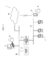
- FIG. 1 is a block diagram illustrating an entire configuration of the information display system in the present embodiment.
- the information display system 1 of the present embodiment is equipped with field devices 11, a field communication server 12, a database server 13, an operation monitoring terminal device 14 (second terminal device), and a portable terminal device 15 (first terminal device).
- the information display system 1 can display a set of device-state-related information generated by the field devices 11 associated with maintenance works.
- the information display system 1 is established in a plant and a factory (hereinafter called simply "plant” as a generic name of them).
- the plant includes an industrial plant such as a chemical industrial plant, a plant managing and controlling a wellhead (for example, a gas field and an oil field), a plant managing and controlling a generation of electric power (for example, water power, fire power, and nuclear power), a plant managing and controlling a power harvesting (for example, solar power and wind power), a plant managing and controlling water supply and sewerage systems, a dam, and so on.
- a control network N1, an application network N2, and a wireless network N3 are disposed in the information display system 1.
- the control network N1 is a wired network set in the field of the plant.
- the field devices 11 and the field communication server 12 are connected to the control network N 1.
- the application network N2 is a wired network set in a monitoring room (operation room) in the plant.
- the field communication server 12, the database server 13, and the operation monitoring terminal device 14 are connected to the application network N2.
- the wireless network N3 is a wireless network set in the field of the plant.
- the portable terminal device 15 is connected to the wireless network N3. Because the wireless network N3 is connected to the application network N2, the portable terminal device 15 can access to the field communication server 12 and the database server 13, which are connected to the application network N2, via the wireless network N3.
- the field devices 11 are such as a sensor device (for example, a flowmeter and a temperature sensor), a valve device (for example, a flow control valve and an on-off valve), an actuator device (for example, a fan and a motor), an imaging device (for example, a camera and a video camera recording circumstances and objects in the plant), a sound device (for example, a microphone collecting abnormal noise in the plant, and a speaker generating alarm sound), a position detection device outputting position information of each device, and other devices.
- a sensor device for example, a flowmeter and a temperature sensor
- a valve device for example, a flow control valve and an on-off valve
- an actuator device for example, a fan and a motor
- an imaging device for example, a camera and a video camera recording circumstances and objects in the plant
- a sound device for example, a microphone collecting abnormal noise in the plant, and a speaker generating alarm sound
- a position detection device outputting position information of each device, and other devices.
- the field devices 11 are disposed in the field of the plant. All of the each field devices 11 are managed (controlled) by a controller (not shown). The field devices 11 have a self-diagnosis function of diagnosing a self-state. The field devices 11 transmit the device-state-related information to the controller (not shown). The device-state-related information transmitted by the field devices 11 includes information (status) representing a result of the self-diagnosis and information (alarm) representing an abnormality occurred in the field devices 11.
- the field communication server 12 performs a communication (for example, a semi-synchronization type communication) with the controller controlling the field devices 11.
- the field communication server 12 collects measurement results (process values) of the field devices 11 and diagnostic information representing the result of the self-diagnosis of the field devices 11.
- the field communication server 12 is disposed in the monitoring room in the plant.
- the database server 13 receives the device-state-related information generated by the field devices 11 associated with the maintenance works conducted in the plant.
- the database server 13 stores various types of data which are necessary for displaying the received information on the operation monitoring terminal device 14 and the portable terminal device 15.
- the database server 13 stores master data and the device-state-related information (the process values of the field devices 11 and the diagnostic information of the field devices 11).
- the master data represents the field devices associated with the maintenance works conducted in the plant. Although details will be described later, the master data is created in accordance with an instruction from the operation monitoring terminal device 14.
- the device-state-related information (the process values and the diagnostic information) is received from the field communication server 12.
- the database server 13 is also disposed in the monitoring room in the plant.
- FIG. 2 is a drawing illustrating an example of the master data used in the present embodiment.
- the "tag”, the "threshold", and the “message” are associated with the "work name”.
- the "work name” is a name of the maintenance work to be conducted in the plant.
- the "work name” is set by a person (in the present embodiment, a plant operator M) operating the operation monitoring terminal device 14.
- the "tag” is identification information which is set to the each field device 11 so as to easily identify the field device 11. Because the "tag” is associated with the "work name”, the “tag” means information representing the field device 11 associated with the maintenance work to be conducted in the plant. In the example shown in FIG. 2 , the work name "boiler exchange work” is associated with the tags "PT1001", “LIC511", and "PTL211".
- the "threshold” is a value which is set for determining whether the process value generated by the field device 11 is abnormal or not. In a case of a normal condition, the process value generated by the field device 11 is generally within a certain range. For the reason, an upper threshold and a lower threshold are set as the "threshold". In the example shown in FIG. 2 , the upper threshold “TH11” and the lower threshold “TH12" are associated with the field device to which the tag "PT1001" is set.
- the "message” is a character string for alerting the field worker W and the plant operator M in a case where the process value generated by field device 11 exceeds the threshold associated with the field device 11. It is preferable that the "message” includes an alert representing a process value exceeding the threshold so as to display a current state, and the “message” includes a procedure which is to be conducted so as to prevent a prospective trouble.
- the alert "temperature in refrigerant tank exceeds threshold” and the procedure "urgently stop boiler and evacuate” are associated with the work name "boiler exchange work".
- the process values and the diagnostic information which are received from the field communication server 12 are associated with the "work name" included in the master data, and the process values and the diagnostic information are stored in the database server 13.
- the tags "PT1001", “LIC511", and "PTL211" are associated with the work name "boiler exchange work”.
- the process values and the diagnostic information generated by the field devices to which these tags are set are associated with time information representing when the process values and the diagnostic information are obtained.
- the process values and the diagnostic information are also associated with the work name "boiler exchange work”.
- the process values and the diagnostic information are stored in the database server 13.
- the operation monitoring terminal device 14 is operated by the plant operator M.
- the operation monitoring terminal device 14 is a terminal device for monitoring the operation state of the plant. Specifically, the operation monitoring terminal device 14 receives the process values and the diagnostic information of the field device 11 collected by the field communication server 12, and the operation monitoring terminal device 14 displays the operation state of the plant entirely or partially in accordance with an instruction from the plant operator M.
- the operation monitoring terminal device 14 manages the operation state of the plant by controlling the controller (not shown) in accordance with an instruction from the plant operator M.
- the operation monitoring terminal device 14 creates the master data in accordance with an instruction from the plant operator M, or the operation monitoring terminal device 14 displays the set of the device-state-related information generated by the field devices 11 associated with the maintenance work to be conducted in the plant in accordance with the created master data. Although details will be described later, the operation monitoring terminal device 14 can display the same contents as the display contents of the portable terminal device 15 which is used by the field worker W, by identifying an ID (identifier) allocated to the portable terminal device 15 in accordance with an instruction from the plant operator M.
- the operation monitoring terminal device 14 is implemented as a desktop computer which is equipped with an input (for example, a keyboard and a mouse) and a display (for example, a liquid crystal display device).
- the portable terminal device 15 is operated by the field worker W.
- the portable terminal device 15 is a terminal device used for obtaining the process values and the diagnostic information.
- the portable terminal device 15 can access to the field communication server 12 and the database server 13 which are connected to the application network N2 via the wireless network N3. For the reason, as is the case with the operation monitoring terminal device 14, in accordance with an instruction from the field worker W, the portable terminal device 15 can display the set of the device-state-related information generated by the field devices 11 associated with the maintenance work to be conducted in the plant in accordance with the master data.
- the portable terminal device 15 is implemented as a notebook computer which is equipped with an input (for example, a keyboard and a mouse) and a display device (for example, a liquid crystal display device), a tablet computer which is equipped with a touch panel, a PDA (Personal Digital Assistant), or the like.
- an input for example, a keyboard and a mouse
- a display device for example, a liquid crystal display device
- a tablet computer which is equipped with a touch panel
- PDA Personal Digital Assistant
- a CPU Central Processing Unit disposed in a computer runs one or more programs for implementing the functions (a master data creating function and a display function in accordance with the master data) of the operation monitoring terminal device 14 and the function (a display function in accordance with the master data) of the portable terminal device 15. Therefore, software and hardware resources cooperate with each other so that the functions of the operation monitoring terminal device 14 and the portable terminal device 15 can be implemented.
- the one or more programs for implementing the functions may be stored in a non-transitory computer readable storage medium such as a CD-ROM or DVD (registered trademark) -ROM, and the storage medium may be distributed. Also, the one or more programs may be distributed via an external network such as the Internet.
- the functions may be implemented as software by reading the one or more programs out of the storage medium and installing the one or more programs in the computer. Also, the functions may be implemented as software by downloading the one or more programs via the external network and installing the one or more programs in the computer.
- FIG. 3 is a drawing illustrating an example of the display screen of the operation monitoring terminal device and the portable terminal device in the present embodiment.
- a peripheral process monitoring screen WD1 shown in FIG. 3 is displayed on the operation monitoring terminal device 14 and the portable terminal device 15 respectively.
- the peripheral process monitoring screen WD1 is a screen which can display the set of the device-state-related information generated by the field devices 11 associated with the maintenance work to be conducted in the plant.
- contents of the peripheral process monitoring screen WD1 displayed on the operation monitoring terminal device 14 is the same as contents of the peripheral process monitoring screen WD1 displayed on the portable terminal device 15.
- contents of the peripheral process monitoring screen WD1 displayed on the operation monitoring terminal device 14 is different from contents of the peripheral process monitoring screen WD1 displayed on the portable terminal device 15.
- the peripheral process monitoring screen WD1 includes a process value display area R1 a diagnostic information display area R2, a message display area R3, a master data display button B1, and a start button B2.
- the process value display area R1 is an area where the process values P1 to P3 (first information), which are generated by the field devices 11 associated with the maintenance works conducted in the plant, are displayed along with the legends H. In other words, the process values P1 to P3 generated by the field devices 11 are displayed with the process values P1 to P3 associated with the legends H for identifying the field devices 11.
- one of the thresholds which are preliminarily set to the process values P1 to P3 is displayed.
- the upper threshold TH1 and the lower threshold TH2 are displayed in the process value display area R1.
- thresholds set to the process value P1 thresholds set to the process value P2, and thresholds set to the process value P3 can be displayed by selecting one of the process values P1 to P3 displayed in the process value display area R1.
- the diagnostic information display area R2 is an area where the diagnostic information D1 (second information), which is generated by the field devices 11 associated with the maintenance works conducted in the plant, is displayed along with the tags T.
- the diagnostic information D1 generated by the field devices 11 is displayed along with the tags T for identifying the field devices 11.
- the diagnostic information D1 is displayed along with icons indicating contents of the diagnostic information D1, so that the plant operator M and the field worker W can intuitively understand the diagnostic information D1.
- the message display area R3 is an area where the message shown in FIG. 2 is displayed.
- the message is displayed in the message display area R3 so as to alert the field worker W and the plant operator M.
- the messages including the alert "temperature in refrigerant tank exceeds threshold” and the procedure "urgently stop boiler and evacuate” are displayed.
- the messages are displayed along with an alert icon (a mark in which an exclamation mark is in a circle).
- the master data display button B1 is a button for reading the master data out of the database server 13 and displaying the master data. By clicking the master data display button B1 by using a cursor C, the list L1 (shown in FIG. 4 ) of the "work name" included in the master data is displayed. After selecting any one of "work name" from the list and clicking the start button B2, the display contents of the peripheral process monitoring screen WD1 can be changed.
- the start button B2 is a button for starting displaying with respect to the peripheral process monitoring screen WD 1, or for changing the display contents of the peripheral process monitoring screen WD1.
- the operation monitoring terminal device 14 can start a program for displaying the peripheral process monitoring screen WD1 in a "data creating mode” or a “monitoring mode".
- the "data creating mode” is a mode for creating the master data by setting the process values and the thresholds which are to be displayed on the peripheral process monitoring screen WD1.
- the "monitoring mode” is a mode for referring to the process values and the thresholds by using the created master data.
- the portable terminal device 15 can start a program for displaying the peripheral process monitoring screen WD1 in the "monitoring mode", but the portable terminal device 15 cannot start the program in the "data creating mode".
- the plant operator M operates the operation monitoring terminal device 14 so as to start the program for displaying the peripheral process monitoring screen WD1 in a "data creating mode". Also, the plant operator M operates the operation monitoring terminal device 14 so as to display a transmitter select screen WD2 for selecting one of the field devices 11 on the operation monitoring terminal device 14. By these operations, as shown in FIG. 4 , the peripheral process monitoring screen WD1 and the transmitter select screen WD2 are displayed on the operation monitoring terminal device 14.
- FIG. 4 is a drawing illustrating an example of the display contents of the operation monitoring terminal device when the master data is created.
- the plant operator M operates the operation monitoring terminal device 14 to display the device to which the maintenance work is conducted (the maintenance target device), the peripheral devices relating to the maintenance target device, and the field devices 11 disposed in the maintenance target device and the peripheral devices, on the transmitter select screen WD2.
- the transmitter select screen WD2 is created by using plant information (information representing positions and connection relations of various types of devices and the field devices 11 which are disposed in the plant) which is preliminarily stored in the database server 13.
- the maintenance target device is the "boiler”
- the peripheral devices are the "distillation tank” and the "refrigerant tank”.
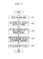
- FIG. 5 is a flowchart illustrating a creation process of the master data in the present embodiment.
- the operation monitoring terminal device 14 inputs the work name of the maintenance work to be conducted in the plant, in accordance with operations of the plant operator M (step S11). So as to easily understand, for example, the work name "boiler exchange work" is input.
- the operation monitoring terminal device 14 selects the field devices 11 associated with the maintenance work in accordance with operations of the plant operator M (step S12). Specifically, as shown in FIG. 4 , the plant operator M selects one of the tags included in the device list L2 (a list of the tags of the field devices 11 displayed in the transmitter select screen WD2) by using the cursor C. The plant operator M drags and drops the selected tag to the peripheral process monitoring screen WD1. The operation monitoring terminal device 14 selects the field device 11 corresponding to the tag dragged and dropped by the plant operator M. In FIG. 4 , the field device 11 to which the tag "PT1001" is set is dragged and dropped.
- the process of selecting the field device 11 is performed more than once in accordance with operations of the plant operator M. Specifically, the process of selecting the field device 11 is performed as often as a number of the field devices 11 to which the plant operator M intends to relate the maintenance work "boiler exchange work". In the example shown in FIG. 4 , three field devices 11 to which the tags "PT1001", “LIC511", and "PTL211" are set respectively are selected.
- the process values P1 to P3 generated by the selected field devices 11 are displayed in the process value display area R1 in the peripheral process monitoring screen WD1
- the diagnostic information D1 generated by the selected field devices 11 is displayed in the diagnostic information display area R2 in the peripheral process monitoring screen WD1.
- the operation monitoring terminal device 14 sets the thresholds with respect to the process values P1 to P3 generated by the selected field devices 11 (step S13). Specifically, the plant operator M selects the process values P1 to P3 or the legends H which are displayed in the process value display area R1 in the peripheral process monitoring screen WD1 by using the cursor C. The plant operator M inputs the upper threshold TH11 and the lower threshold TH12 of the selected process values P1 to P3. The operation monitoring terminal device 14 sets the upper threshold TH11 and the lower threshold TH12 input by the plant operator M with respect to the process values P1 to P3. A scale G is automatically displayed in accordance with magnitude of the process values P1 to P3 displayed in the process value display area R1. The plant operator M inputs the upper threshold TH11 and the lower threshold TH12 with reference to the scale G.
- the operation monitoring terminal device 14 inputs the message, which is to be displayed in the peripheral process monitoring screen WD1 in a case where at least one of the process values P1 to P3 of the selected field device 11 exceeds the threshold (step S14).
- the plant operator M selects the message display area R3 in the peripheral process monitoring screen WD1, and the plant operator M inputs the message in the selected message display area R3.
- the operation monitoring terminal device 14 receives the message input by the plant operator M.
- the operation monitoring terminal device 14 creates the master data, and the operation monitoring terminal device 14 registers the created master data with the database server 13 (step S15). Specifically, the operation monitoring terminal device 14 created the master data in which the "tag" of the field device 11 selected in the step S12, the "threshold” set in the step S13, and the “message” input in the step S14 are related with respect to the "work name” input in the step S11, and the operation monitoring terminal device 14 stores the created master data in the database server 13.
- the list L1 of the "work name” included in the master data is displayed. After one of the "work name” in the list L1 is selected by using the cursor C, the "tag”, the “threshold”, and the "message" which are associated with the selected "work name” can be edited.
- the operation monitoring terminal device 14 starts the program for displaying the peripheral process monitoring screen WD1 in the "monitoring mode" in accordance with operations of the plant operator M, or the portable terminal device 15 starts the program for displaying the peripheral process monitoring screen WD1 in the "monitoring mode” in accordance with operations of the field worker W.
- FIG. 6 is a flowchart illustrating a display process of the device-state-related information in the present embodiment.
- the master data stored in the database server 13 is read out of the database server 13.
- the portable terminal device 15 displays the list L1 (shown in FIG. 4 ) of the "work name" included in the master data (step S21).
- the portable terminal device 15 identifies the field devices that are associated with the maintenance work in accordance with the master data, and the portable terminal device 15 identifies the set of the device-state-related information which is generated by the field devices.
- the portable terminal device 15 displays, for example, the peripheral process monitoring screen WD1 shown in FIG. 3 in accordance with the process values and the diagnostic information (the set of the device-state-related information) read out of the database server 13 (step S23).
- the process values P1 to P3 which are generated by the field devices 11 to which the tags "PT1001", “L1C511", and "PTL211" are set, are displayed in the process value display area R1 along with the legends H.
- the diagnostic information D1 generated by the field devices 11 is displayed in the diagnostic information display area R2 with the diagnostic information D1 associated with the tag T.
- the field worker W can understand how many peripheral devices and field devices 11 relate to the maintenance work to be conducted in the plant. Also, in accordance with the set of the device-state-related information (the process values P1 to P3 and the diagnostic information D1) generated by the field devices 11 associated with the maintenance work to be conducted in the plant, the field worker W can understand the states of the peripheral devices in which the field devices 11 are disposed.
- the portable terminal device 15 determines whether at least one of the process values P1 to P3 displayed in the process value display area R1 exceeds the associated threshold or not (step S24). In a case where the portable terminal device 15 determines that at least one of the process values P1 to P3 exceeds the associated threshold (step S24: YES), the portable terminal device 15 alerts (step S25).
- the messages including the alert "temperature in refrigerant tank exceeds threshold” and the procedure “urgently stop boiler and evacuate” are displayed in the message display area R3 in the peripheral process monitoring screen WD1.
- sound (buzzer) and vibration may be used along with the message as the alert.
- Information representing a type of the alert and importance of the alert may be set to the master data along with the message. In a case of generating the alert, patterns of the sound and the vibration may be changed in accordance with the type of the alert and the importance of the alert.
- FIG. 7 is a drawing illustrating an example of the terminal list displayed on the operation monitoring terminal device in the present embodiment.
- the operation monitoring terminal device 14 and the portable terminal devices 15 can communicate with each other via the application network N2 and the wireless network N3. For the reason, the operation monitoring terminal device 14 can recognize the portable terminal devices 15 connected to the wireless network N3, and the operation monitoring terminal device 14 can display the terminal list L3 shown in FIG. 7 .
- the operation monitoring terminal device 14 displays the peripheral process monitoring screen WD1 which is the same as the peripheral process monitoring screen WD1 displayed on the portable terminal device 15 which is associated with the selected ID. While the operation monitoring terminal device 14 displays the peripheral process monitoring screen WD1, in a case where the alert is generated from the portable terminal device 15 which is associated with the selected ID, the same alert (for example, message, sound, and vibration) is generated from the operation monitoring terminal device 14.
- the same alert for example, message, sound, and vibration
- the master data indicating the field devices associated with the maintenance works conducted in the plant is stored in the database server 13, in a case where the work name used for identifying the maintenance work to be conducted in the plant is input, the process values P1 to P3 and the diagnostic information D1 which are generated by the field devices 11 associated with the maintenance work identified by the input work name are displayed in accordance with the master data. For the reason, even if the plant operator M does not have sufficient knowledge and experience, the plant operator M can display the states of the peripheral devices relating to the maintenance target device. Therefore, the maintenance work can be easily conducted.
- the upper threshold TH1 and the lower threshold TH2 are displayed along with the process values P1 to P3. Therefore, even if the plant operator M does not have sufficient knowledge and experience, the plant operator M can immediately determine whether the states of the peripheral devices are within a normal range or not. Further, in the present embodiment, in a case where at least one of the process values P1 to P3 exceeds the thresholds (the upper threshold TH1 and the lower threshold TH2), the message is displayed. Therefore, in a case where an abnormality occurs, the field worker W can immediately perform a danger avoidance action.
- the operation monitoring terminal device 14 can display the same contents as the display contents of the portable terminal device 15 which is operated by the field worker W, the plant operator M can find an abnormality of the field, and the plant operator M can immediately perform the danger avoidance action. Because the plant operator M can easily understand the conditions such as the abnormality of the field with reference to the display contents of the operation monitoring terminal device 14, a cumbersome work, in which the field worker W explains the conditions of the field to the plant operator M by using a cell-phone, can be omitted (or suppressed).
- the present invention is not restricted to the above-described embodiments, and can be freely modified within the scope thereof.
- the application network N2 and the wireless network N3 may be connected to each other via the Internet. In this case, even if the monitoring rooms and the fields in the plant exist over a range of several kilometers, the present embodiment can be implemented.
- the sound and the vibration are generated along with the message as the alert.
- the portable terminal device 15 is a compact terminal, only the sound and the vibration may be generated without the message.
- the field communication server 12, the database server 13, and the operation monitoring terminal device 14 are connected to each other via the application network N2.
- the field communication server 12, the database server 13, and the operation monitoring terminal device 14 may be integral with each other.
- the maintenance work conducted in the plant is associated with three field devices 11, the present invention is not restricted to the number.
- at least one of the field devices 11 may be associated with the maintenance work.
- the term "configured” is used to describe a component, unit or part of a device includes hardware and/or software that is constructed and/or programmed to carry out the desired function.
- unit is used to describe a component, unit or part of a hardware and/or software that is constructed and/or programmed to carry out the desired function.
- Typical examples of the hardware may include, but are not limited to, a device and a circuit.
Landscapes
- Engineering & Computer Science (AREA)
- Business, Economics & Management (AREA)
- Physics & Mathematics (AREA)
- General Physics & Mathematics (AREA)
- Human Resources & Organizations (AREA)
- Theoretical Computer Science (AREA)
- Marketing (AREA)
- General Business, Economics & Management (AREA)
- Economics (AREA)
- Entrepreneurship & Innovation (AREA)
- Tourism & Hospitality (AREA)
- Operations Research (AREA)
- Quality & Reliability (AREA)
- Strategic Management (AREA)
- Human Computer Interaction (AREA)
- Automation & Control Theory (AREA)
- Health & Medical Sciences (AREA)
- Computing Systems (AREA)
- General Health & Medical Sciences (AREA)
- Medical Informatics (AREA)
- Computer Networks & Wireless Communication (AREA)
- Signal Processing (AREA)
- Testing And Monitoring For Control Systems (AREA)
Abstract
Description
- The disclosure relates to an information display method, an information display apparatus, an information display system, and a non-transitory computer readable storage medium.
- Priority is claimed on Japanese Patent Application No.
2014-104895, filed May 21,2014 - In a plant and a factory (hereinafter called simply "plant" as a generic name of them), a DCS (Distributed Control System) is established, and an advanced automatic operation is implemented. In the distributed control system, field devices (for example, a measurement device, a manipulation device, a display device, an alarm device, and other devices) and a controller controlling the field devices are connected to each other via a network. In the plant in which the distributed control system is established, so as to prevent abnormal operations and keep measurement accuracy, a worker conducts maintenance of the field device periodically or non-periodically.
- Recently, so as to efficiently maintain the field devices, an integrated device management system such as a PRM (Plant Resource Manager) (registered trademark) is often established along with the distributed control system. The integrated device management system has a function (maintenance information management function) for managing a maintenance schedule of each field device, a function (maintenance check work function) for monitoring a condition of the each field device and adjusting the each field device, and a function (maintenance check result management function) for recording results of the maintenance check and reporting the results of the maintenance check.
- In the Japanese Unexamined Patent Application Publication No.
2003-333121 - The maintenance of the plant may not be conducted while the plant is entirely stopped, and the maintenance of the plant may be conducted while only a part of the processes are stopped. For example, there is a case that a chemical material storage tank is checked and exchanged, in a state where chemical reactions in peripheral devices relating to the chemical material storage tank are suppressed by manually closing valves disposed on a pipe line connected to the chemical material storage tank, and the processes are stopped. In a case of conducting the maintenance, along with a maintenance target device (in the example described above, the chemical material storage tank), there is a need to obtain states of the peripheral devices relating to the maintenance target device.
- The maintenance of the plant is conducted in accordance with a documented procedure which is preliminarily determined and documented by the plant operator and a field worker. Specifically, the plant operator observes the states of the field devices by operating the integrated device management system, and the plant operator works in accordance with the determined procedure while the plant operator checks information (for example, actual process values and actual device states) by talking with the field worker on a cell-phone. In a case of a field device installed in a position where the field worker can approach, the field worker visually checks contents of a display screen of the field device, or the field worker obtains necessary information by connecting a special-purpose terminal to the field device. On the other hand, in a case of a field device installed in a position where the field worker cannot approach, the field worker asks the plant operator so as to obtain the process values and the states of the field device.
- Although the plant operator can check the maintenance target device by using the integrated device management system, in a case where the plant operator does not have sufficient knowledge and experience, it is difficult for the plant operator to check the peripheral devices relating to the maintenance target device. Even if the field worker can identify the peripheral devices relating to the maintenance target device, in a case where the field worker cannot approach the field devices which are disposed in the identified peripheral devices, the field worker cannot visually check the contents of the display screen of the field device, and the field worker cannot obtain the necessary information by connecting the special-purpose terminal to the field device. For the reason, the original works (for example, monitoring the states of the field devices) cannot be efficiently performed.
- An information display method may include inputting, by an input, a work information for identifying a maintenance work to be conducted in a plant, and displaying, by a display, a set of device-state-related information generated by at least a field device associated with the maintenance work identified by the work information.
- Further features and aspects of the present disclosure will become apparent from the following detailed description of exemplary embodiments with reference to the attached drawings.
-
-
FIG. 1 is a block diagram illustrating an entire configuration of an information display system in a present embodiment. -
FIG. 2 is a drawing illustrating an example of master data used in the present embodiment. -
FIG. 3 is a drawing illustrating an example of a display screen of an operation monitoring terminal device and a portable terminal device in the present embodiment. -
FIG. 4 is a drawing illustrating an example of display contents of the operation monitoring terminal device when the master data is created. -
FIG. 5 is a flowchart illustrating a creation process of the master data in the present embodiment. -
FIG. 6 is a flowchart illustrating a display process of the device-state-related information in the present embodiment. -
FIG. 7 is a drawing illustrating an example of a terminal list displayed on the operation monitoring terminal device in the present embodiment. - The embodiments of the present invention will be now described herein with reference to illustrative preferred embodiments. Those skilled in the art will recognize that many alternative preferred embodiments can be accomplished using the teaching of the present invention and that the present invention is not limited to the preferred embodiments illustrated herein for explanatory purposes.
- An aspect of the present invention is to provide an information display method, an information display apparatus, an information display system, and a non-transitory computer readable storage medium which can display the states of the peripheral devices relating to the maintenance target device, and can easily perform the maintenance thereby.
- The information display method, the information display apparatus, the information display system, and the non-transitory computer readable storage medium of the present embodiment will be described below with reference to drawings.
FIG. 1 is a block diagram illustrating an entire configuration of the information display system in the present embodiment. - As shown in
FIG. 1 , the information display system 1 of the present embodiment is equipped with field devices 11, afield communication server 12, adatabase server 13, an operation monitoring terminal device 14 (second terminal device), and a portable terminal device 15 (first terminal device). The information display system 1 can display a set of device-state-related information generated by the field devices 11 associated with maintenance works. - For example, the information display system 1 is established in a plant and a factory (hereinafter called simply "plant" as a generic name of them). The plant includes an industrial plant such as a chemical industrial plant, a plant managing and controlling a wellhead (for example, a gas field and an oil field), a plant managing and controlling a generation of electric power (for example, water power, fire power, and nuclear power), a plant managing and controlling a power harvesting (for example, solar power and wind power), a plant managing and controlling water supply and sewerage systems, a dam, and so on.
- As shown in
FIG. 1 , a control network N1, an application network N2, and a wireless network N3 are disposed in the information display system 1. For example, the control network N1 is a wired network set in the field of the plant. The field devices 11 and thefield communication server 12 are connected to the control network N 1. For example, the application network N2 is a wired network set in a monitoring room (operation room) in the plant. Thefield communication server 12, thedatabase server 13, and the operationmonitoring terminal device 14 are connected to the application network N2. - The wireless network N3 is a wireless network set in the field of the plant. The
portable terminal device 15 is connected to the wireless network N3. Because the wireless network N3 is connected to the application network N2, theportable terminal device 15 can access to thefield communication server 12 and thedatabase server 13, which are connected to the application network N2, via the wireless network N3. - The field devices 11 are such as a sensor device (for example, a flowmeter and a temperature sensor), a valve device (for example, a flow control valve and an on-off valve), an actuator device (for example, a fan and a motor), an imaging device (for example, a camera and a video camera recording circumstances and objects in the plant), a sound device (for example, a microphone collecting abnormal noise in the plant, and a speaker generating alarm sound), a position detection device outputting position information of each device, and other devices.
- The field devices 11 are disposed in the field of the plant. All of the each field devices 11 are managed (controlled) by a controller (not shown). The field devices 11 have a self-diagnosis function of diagnosing a self-state. The field devices 11 transmit the device-state-related information to the controller (not shown). The device-state-related information transmitted by the field devices 11 includes information (status) representing a result of the self-diagnosis and information (alarm) representing an abnormality occurred in the field devices 11.
- The
field communication server 12 performs a communication (for example, a semi-synchronization type communication) with the controller controlling the field devices 11. Thefield communication server 12 collects measurement results (process values) of the field devices 11 and diagnostic information representing the result of the self-diagnosis of the field devices 11. For example, thefield communication server 12 is disposed in the monitoring room in the plant. - The
database server 13 receives the device-state-related information generated by the field devices 11 associated with the maintenance works conducted in the plant. Thedatabase server 13 stores various types of data which are necessary for displaying the received information on the operationmonitoring terminal device 14 and theportable terminal device 15. Specifically, thedatabase server 13 stores master data and the device-state-related information (the process values of the field devices 11 and the diagnostic information of the field devices 11). The master data represents the field devices associated with the maintenance works conducted in the plant. Although details will be described later, the master data is created in accordance with an instruction from the operationmonitoring terminal device 14. The device-state-related information (the process values and the diagnostic information) is received from thefield communication server 12. For example, thedatabase server 13 is also disposed in the monitoring room in the plant. -
FIG. 2 is a drawing illustrating an example of the master data used in the present embodiment. As shown inFIG. 2 , in the master data, the "tag", the "threshold", and the "message" are associated with the "work name". The "work name" is a name of the maintenance work to be conducted in the plant. The "work name" is set by a person (in the present embodiment, a plant operator M) operating the operation monitoringterminal device 14. - Although whatever names can be set as the "work name", it is preferable that a person (the field worker W or the plant operator M) referring to the "work name" can easily understand the meaning of the maintenance work. In the example shown in
FIG. 2 , the "boiler exchange work", the "tank wash work", the "tank exchange work", and the "refrigerant tank change work" are set as the work names. - The "tag" is identification information which is set to the each field device 11 so as to easily identify the field device 11. Because the "tag" is associated with the "work name", the "tag" means information representing the field device 11 associated with the maintenance work to be conducted in the plant. In the example shown in
FIG. 2 , the work name "boiler exchange work" is associated with the tags "PT1001", "LIC511", and "PTL211". - The "threshold" is a value which is set for determining whether the process value generated by the field device 11 is abnormal or not. In a case of a normal condition, the process value generated by the field device 11 is generally within a certain range. For the reason, an upper threshold and a lower threshold are set as the "threshold". In the example shown in
FIG. 2 , the upper threshold "TH11" and the lower threshold "TH12" are associated with the field device to which the tag "PT1001" is set. - The "message" is a character string for alerting the field worker W and the plant operator M in a case where the process value generated by field device 11 exceeds the threshold associated with the field device 11. It is preferable that the "message" includes an alert representing a process value exceeding the threshold so as to display a current state, and the "message" includes a procedure which is to be conducted so as to prevent a prospective trouble. In the example shown in
FIG. 2 , the alert "temperature in refrigerant tank exceeds threshold" and the procedure "urgently stop boiler and evacuate" are associated with the work name "boiler exchange work". - The process values and the diagnostic information which are received from the
field communication server 12 are associated with the "work name" included in the master data, and the process values and the diagnostic information are stored in thedatabase server 13. For example, in the example shown inFIG. 2 , the tags "PT1001", "LIC511", and "PTL211" are associated with the work name "boiler exchange work". The process values and the diagnostic information generated by the field devices to which these tags are set are associated with time information representing when the process values and the diagnostic information are obtained. The process values and the diagnostic information are also associated with the work name "boiler exchange work". The process values and the diagnostic information are stored in thedatabase server 13. - The operation monitoring
terminal device 14 is operated by the plant operator M. The operation monitoringterminal device 14 is a terminal device for monitoring the operation state of the plant. Specifically, the operation monitoringterminal device 14 receives the process values and the diagnostic information of the field device 11 collected by thefield communication server 12, and the operation monitoringterminal device 14 displays the operation state of the plant entirely or partially in accordance with an instruction from the plant operator M. The operation monitoringterminal device 14 manages the operation state of the plant by controlling the controller (not shown) in accordance with an instruction from the plant operator M. - The operation monitoring
terminal device 14 creates the master data in accordance with an instruction from the plant operator M, or the operation monitoringterminal device 14 displays the set of the device-state-related information generated by the field devices 11 associated with the maintenance work to be conducted in the plant in accordance with the created master data. Although details will be described later, the operation monitoringterminal device 14 can display the same contents as the display contents of the portableterminal device 15 which is used by the field worker W, by identifying an ID (identifier) allocated to the portableterminal device 15 in accordance with an instruction from the plant operator M. The operation monitoringterminal device 14 is implemented as a desktop computer which is equipped with an input (for example, a keyboard and a mouse) and a display (for example, a liquid crystal display device). - The portable
terminal device 15 is operated by the field worker W. The portableterminal device 15 is a terminal device used for obtaining the process values and the diagnostic information. The portableterminal device 15 can access to thefield communication server 12 and thedatabase server 13 which are connected to the application network N2 via the wireless network N3. For the reason, as is the case with the operation monitoringterminal device 14, in accordance with an instruction from the field worker W, the portableterminal device 15 can display the set of the device-state-related information generated by the field devices 11 associated with the maintenance work to be conducted in the plant in accordance with the master data. The portableterminal device 15 is implemented as a notebook computer which is equipped with an input (for example, a keyboard and a mouse) and a display device (for example, a liquid crystal display device), a tablet computer which is equipped with a touch panel, a PDA (Personal Digital Assistant), or the like. - A CPU (Central Processing Unit) disposed in a computer runs one or more programs for implementing the functions (a master data creating function and a display function in accordance with the master data) of the operation monitoring
terminal device 14 and the function (a display function in accordance with the master data) of the portableterminal device 15. Therefore, software and hardware resources cooperate with each other so that the functions of the operation monitoringterminal device 14 and the portableterminal device 15 can be implemented. - The one or more programs for implementing the functions may be stored in a non-transitory computer readable storage medium such as a CD-ROM or DVD (registered trademark) -ROM, and the storage medium may be distributed. Also, the one or more programs may be distributed via an external network such as the Internet. The functions may be implemented as software by reading the one or more programs out of the storage medium and installing the one or more programs in the computer. Also, the functions may be implemented as software by downloading the one or more programs via the external network and installing the one or more programs in the computer.
- Next, the display screen of the operation monitoring
terminal device 14 which is operated by the plant operator M and the display screen of the portableterminal device 15 which is operated by the field worker W will be described below.FIG. 3 is a drawing illustrating an example of the display screen of the operation monitoring terminal device and the portable terminal device in the present embodiment. In accordance with instructions from the plant operator M and the field worker W, a peripheral process monitoring screen WD1 shown inFIG. 3 is displayed on the operation monitoringterminal device 14 and the portableterminal device 15 respectively. The peripheral process monitoring screen WD1 is a screen which can display the set of the device-state-related information generated by the field devices 11 associated with the maintenance work to be conducted in the plant. - In a case where a work name of the master data instructed by the plant operator M is the same as a work name of the master data instructed by the field worker W, contents of the peripheral process monitoring screen WD1 displayed on the operation monitoring
terminal device 14 is the same as contents of the peripheral process monitoring screen WD1 displayed on the portableterminal device 15. On the other hand, in a case where the work name instructed by the plant operator M is different from the work name instructed by the field worker W, contents of the peripheral process monitoring screen WD1 displayed on the operation monitoringterminal device 14 is different from contents of the peripheral process monitoring screen WD1 displayed on the portableterminal device 15. - As shown in
FIG. 3 , the peripheral process monitoring screen WD1 includes a process value display area R1 a diagnostic information display area R2, a message display area R3, a master data display button B1, and a start button B2. The process value display area R1 is an area where the process values P1 to P3 (first information), which are generated by the field devices 11 associated with the maintenance works conducted in the plant, are displayed along with the legends H. In other words, the process values P1 to P3 generated by the field devices 11 are displayed with the process values P1 to P3 associated with the legends H for identifying the field devices 11. - In the process value display area R1, one of the thresholds which are preliminarily set to the process values P1 to P3 is displayed. In the example shown in
FIG. 3 , the upper threshold TH1 and the lower threshold TH2 are displayed in the process value display area R1. As the upper threshold TH1 and the lower threshold TH2, thresholds set to the process value P1, thresholds set to the process value P2, and thresholds set to the process value P3 can be displayed by selecting one of the process values P1 to P3 displayed in the process value display area R1. - The diagnostic information display area R2 is an area where the diagnostic information D1 (second information), which is generated by the field devices 11 associated with the maintenance works conducted in the plant, is displayed along with the tags T. In other words, the diagnostic information D1 generated by the field devices 11 is displayed along with the tags T for identifying the field devices 11. In the example shown in
FIG. 3 , the diagnostic information D1 is displayed along with icons indicating contents of the diagnostic information D1, so that the plant operator M and the field worker W can intuitively understand the diagnostic information D1. - The message display area R3 is an area where the message shown in
FIG. 2 is displayed. In a case where any one of the process value P1 to P3 generated by the field device 11 exceeds the threshold associated with the field device 11, the message is displayed in the message display area R3 so as to alert the field worker W and the plant operator M. In the example shown inFIG. 3 , the messages including the alert "temperature in refrigerant tank exceeds threshold" and the procedure "urgently stop boiler and evacuate" are displayed. In the example shown inFIG. 3 , the messages are displayed along with an alert icon (a mark in which an exclamation mark is in a circle). - The master data display button B1 is a button for reading the master data out of the
database server 13 and displaying the master data. By clicking the master data display button B1 by using a cursor C, the list L1 (shown inFIG. 4 ) of the "work name" included in the master data is displayed. After selecting any one of "work name" from the list and clicking the start button B2, the display contents of the peripheral process monitoring screen WD1 can be changed. The start button B2 is a button for starting displaying with respect to the peripheral process monitoring screen WD 1, or for changing the display contents of the peripheral process monitoring screen WD1. - Although details will be described later, the operation monitoring
terminal device 14 can start a program for displaying the peripheral process monitoring screen WD1 in a "data creating mode" or a "monitoring mode". The "data creating mode" is a mode for creating the master data by setting the process values and the thresholds which are to be displayed on the peripheral process monitoring screen WD1. On the other hand, the "monitoring mode" is a mode for referring to the process values and the thresholds by using the created master data. The portableterminal device 15 can start a program for displaying the peripheral process monitoring screen WD1 in the "monitoring mode", but the portableterminal device 15 cannot start the program in the "data creating mode". - Next, operations of the information display system 1 will be described below. So as to easily understand, first, an operation of creating the master data (master data creating operation) will be described. Thereafter, an operation of displaying the set of the device-state-related information generated by the field devices 11 when the maintenance work is conducted (information display operation) will be described.
- In a case of creating the master data, first, the plant operator M operates the operation monitoring
terminal device 14 so as to start the program for displaying the peripheral process monitoring screen WD1 in a "data creating mode". Also, the plant operator M operates the operation monitoringterminal device 14 so as to display a transmitter select screen WD2 for selecting one of the field devices 11 on the operation monitoringterminal device 14. By these operations, as shown inFIG. 4 , the peripheral process monitoring screen WD1 and the transmitter select screen WD2 are displayed on the operation monitoringterminal device 14.FIG. 4 is a drawing illustrating an example of the display contents of the operation monitoring terminal device when the master data is created. - As shown in
FIG. 4 , so as to easily select the field devices 11, the plant operator M operates the operation monitoringterminal device 14 to display the device to which the maintenance work is conducted (the maintenance target device), the peripheral devices relating to the maintenance target device, and the field devices 11 disposed in the maintenance target device and the peripheral devices, on the transmitter select screen WD2. The transmitter select screen WD2 is created by using plant information (information representing positions and connection relations of various types of devices and the field devices 11 which are disposed in the plant) which is preliminarily stored in thedatabase server 13. In the example shown inFIG. 4 , for example, the maintenance target device is the "boiler", and the peripheral devices are the "distillation tank" and the "refrigerant tank". - As shown in
FIG. 4 , the operation monitoringterminal device 14 starts creating the master data while the operation monitoringterminal device 14 displays the peripheral process monitoring screen WD1 and the transmitter select screen WD2.FIG. 5 is a flowchart illustrating a creation process of the master data in the present embodiment. When the creation process of the master data is started, the operation monitoringterminal device 14 inputs the work name of the maintenance work to be conducted in the plant, in accordance with operations of the plant operator M (step S11). So as to easily understand, for example, the work name "boiler exchange work" is input. - Next, the operation monitoring
terminal device 14 selects the field devices 11 associated with the maintenance work in accordance with operations of the plant operator M (step S12). Specifically, as shown inFIG. 4 , the plant operator M selects one of the tags included in the device list L2 (a list of the tags of the field devices 11 displayed in the transmitter select screen WD2) by using the cursor C. The plant operator M drags and drops the selected tag to the peripheral process monitoring screen WD1. The operation monitoringterminal device 14 selects the field device 11 corresponding to the tag dragged and dropped by the plant operator M. InFIG. 4 , the field device 11 to which the tag "PT1001" is set is dragged and dropped. - The process of selecting the field device 11 is performed more than once in accordance with operations of the plant operator M. Specifically, the process of selecting the field device 11 is performed as often as a number of the field devices 11 to which the plant operator M intends to relate the maintenance work "boiler exchange work". In the example shown in
FIG. 4 , three field devices 11 to which the tags "PT1001", "LIC511", and "PTL211" are set respectively are selected. When the field devices 11 are selected, the process values P1 to P3 generated by the selected field devices 11 are displayed in the process value display area R1 in the peripheral process monitoring screen WD1, and the diagnostic information D1 generated by the selected field devices 11 is displayed in the diagnostic information display area R2 in the peripheral process monitoring screen WD1. - Thereafter, the operation monitoring
terminal device 14 sets the thresholds with respect to the process values P1 to P3 generated by the selected field devices 11 (step S13). Specifically, the plant operator M selects the process values P1 to P3 or the legends H which are displayed in the process value display area R1 in the peripheral process monitoring screen WD1 by using the cursor C. The plant operator M inputs the upper threshold TH11 and the lower threshold TH12 of the selected process values P1 to P3. The operation monitoringterminal device 14 sets the upper threshold TH11 and the lower threshold TH12 input by the plant operator M with respect to the process values P1 to P3. A scale G is automatically displayed in accordance with magnitude of the process values P1 to P3 displayed in the process value display area R1. The plant operator M inputs the upper threshold TH11 and the lower threshold TH12 with reference to the scale G. - Next, the operation monitoring
terminal device 14 inputs the message, which is to be displayed in the peripheral process monitoring screen WD1 in a case where at least one of the process values P1 to P3 of the selected field device 11 exceeds the threshold (step S14). For example, the plant operator M selects the message display area R3 in the peripheral process monitoring screen WD1, and the plant operator M inputs the message in the selected message display area R3. The operation monitoringterminal device 14 receives the message input by the plant operator M. - After these processes are completed, when the plant operator M closes the peripheral process monitoring screen WD1 displayed on the operation monitoring
terminal device 14, a confirmation screen for confirming an update of the master data is displayed. In a case where the plant operator M instructs the update of the master data, the operation monitoringterminal device 14 creates the master data, and the operation monitoringterminal device 14 registers the created master data with the database server 13 (step S15). Specifically, the operation monitoringterminal device 14 created the master data in which the "tag" of the field device 11 selected in the step S12, the "threshold" set in the step S13, and the "message" input in the step S14 are related with respect to the "work name" input in the step S11, and the operation monitoringterminal device 14 stores the created master data in thedatabase server 13. - In a case where the
database server 13 has already registered the master data, by clicking the master data display button B1 in the peripheral process monitoring screen WD1, the list L1 of the "work name" included in the master data is displayed. After one of the "work name" in the list L1 is selected by using the cursor C, the "tag", the "threshold", and the "message" which are associated with the selected "work name" can be edited. - When the maintenance work is conducted in the plant, in a case where the set of the device-state-related information generated by the field devices 11 associated with the maintenance work is displayed, the operation monitoring
terminal device 14 starts the program for displaying the peripheral process monitoring screen WD1 in the "monitoring mode" in accordance with operations of the plant operator M, or the portableterminal device 15 starts the program for displaying the peripheral process monitoring screen WD1 in the "monitoring mode" in accordance with operations of the field worker W. So as to describe simply, an example of displaying the set of the device-state-related information on the portableterminal device 15 which is operated by the field worker W will be described below. - When the program is started, the portable
terminal device 15 which is operated by the field worker W displays the peripheral process monitoring screen WD1. However, at this time, nothing is displayed in the process value display area R1, the diagnostic information display area R2, and the message display area R3 in the peripheral process monitoring screen WD1. After such peripheral process monitoring screen WD1 is displayed, processes of the flowchart shown inFIG. 6 are executed.FIG. 6 is a flowchart illustrating a display process of the device-state-related information in the present embodiment. - First, when the field worker W clicks the master data display button B1 in the peripheral process monitoring screen WD1 by using the cursor C, the master data stored in the
database server 13 is read out of thedatabase server 13. The portableterminal device 15 displays the list L1 (shown inFIG. 4 ) of the "work name" included in the master data (step S21). - While the list L1 is displayed, when the field worker W selects one of the work names included in the list L1 by using the cursor C and clicks the start button B2, the selected work name (work information) is input to the portable terminal device 15 (step S22). Thereafter, the "tag", the "threshold", and the "message" which are associated with the input work name are read from the master data, and the process values and the diagnostic information which are associated with the input work name are read out of the
database server 13. In other words, the portableterminal device 15 identifies the field devices that are associated with the maintenance work in accordance with the master data, and the portableterminal device 15 identifies the set of the device-state-related information which is generated by the field devices. - The portable
terminal device 15 displays, for example, the peripheral process monitoring screen WD1 shown inFIG. 3 in accordance with the process values and the diagnostic information (the set of the device-state-related information) read out of the database server 13 (step S23). In a case where the "boiler exchange work" is selected from the list L1, as shown inFIG. 3 , the process values P1 to P3, which are generated by the field devices 11 to which the tags "PT1001", "L1C511", and "PTL211" are set, are displayed in the process value display area R1 along with the legends H. Also, the diagnostic information D1 generated by the field devices 11 is displayed in the diagnostic information display area R2 with the diagnostic information D1 associated with the tag T. - With reference to the peripheral process monitoring screen WD1, the field worker W can understand how many peripheral devices and field devices 11 relate to the maintenance work to be conducted in the plant. Also, in accordance with the set of the device-state-related information (the process values P1 to P3 and the diagnostic information D1) generated by the field devices 11 associated with the maintenance work to be conducted in the plant, the field worker W can understand the states of the peripheral devices in which the field devices 11 are disposed.
- While the peripheral process monitoring screen WD1 shown in
FIG. 3 is displayed, the portableterminal device 15 determines whether at least one of the process values P1 to P3 displayed in the process value display area R1 exceeds the associated threshold or not (step S24). In a case where the portableterminal device 15 determines that at least one of the process values P1 to P3 exceeds the associated threshold (step S24: YES), the portableterminal device 15 alerts (step S25). - For example, as shown in
FIG. 3 , the messages including the alert "temperature in refrigerant tank exceeds threshold" and the procedure "urgently stop boiler and evacuate" are displayed in the message display area R3 in the peripheral process monitoring screen WD1. Because the field worker W's hands are often full for the work, sound (buzzer) and vibration may be used along with the message as the alert. Information representing a type of the alert and importance of the alert may be set to the master data along with the message. In a case of generating the alert, patterns of the sound and the vibration may be changed in accordance with the type of the alert and the importance of the alert. - While the field worker W uses the portable
terminal device 15 for working, in a case where the plant operator M instructs the operation monitoringterminal device 14 to display a list of the portableterminal devices 15, the operation monitoringterminal device 14 displays a terminal list L3 shown inFIG. 7. FIG. 7 is a drawing illustrating an example of the terminal list displayed on the operation monitoring terminal device in the present embodiment. As shown inFIG. 1 , the operation monitoringterminal device 14 and the portableterminal devices 15 can communicate with each other via the application network N2 and the wireless network N3. For the reason, the operation monitoringterminal device 14 can recognize the portableterminal devices 15 connected to the wireless network N3, and the operation monitoringterminal device 14 can display the terminal list L3 shown inFIG. 7 . - When the plant operator M selects the ID (for example, the ID "00888876") displayed in the terminal list L3 by using the cursor C shown in
FIG. 7 , the operation monitoringterminal device 14 displays the peripheral process monitoring screen WD1 which is the same as the peripheral process monitoring screen WD1 displayed on the portableterminal device 15 which is associated with the selected ID. While the operation monitoringterminal device 14 displays the peripheral process monitoring screen WD1, in a case where the alert is generated from the portableterminal device 15 which is associated with the selected ID, the same alert (for example, message, sound, and vibration) is generated from the operation monitoringterminal device 14. - As described above, in the present embodiment, the master data indicating the field devices associated with the maintenance works conducted in the plant is stored in the
database server 13, in a case where the work name used for identifying the maintenance work to be conducted in the plant is input, the process values P1 to P3 and the diagnostic information D1 which are generated by the field devices 11 associated with the maintenance work identified by the input work name are displayed in accordance with the master data. For the reason, even if the plant operator M does not have sufficient knowledge and experience, the plant operator M can display the states of the peripheral devices relating to the maintenance target device. Therefore, the maintenance work can be easily conducted. - In the present embodiment, the upper threshold TH1 and the lower threshold TH2 are displayed along with the process values P1 to P3. Therefore, even if the plant operator M does not have sufficient knowledge and experience, the plant operator M can immediately determine whether the states of the peripheral devices are within a normal range or not. Further, in the present embodiment, in a case where at least one of the process values P1 to P3 exceeds the thresholds (the upper threshold TH1 and the lower threshold TH2), the message is displayed. Therefore, in a case where an abnormality occurs, the field worker W can immediately perform a danger avoidance action.
- In the present embodiment, because the operation monitoring
terminal device 14 can display the same contents as the display contents of the portableterminal device 15 which is operated by the field worker W, the plant operator M can find an abnormality of the field, and the plant operator M can immediately perform the danger avoidance action. Because the plant operator M can easily understand the conditions such as the abnormality of the field with reference to the display contents of the operation monitoringterminal device 14, a cumbersome work, in which the field worker W explains the conditions of the field to the plant operator M by using a cell-phone, can be omitted (or suppressed). - Although an information display method, an information display apparatus, an information display system, and a non-transitory computer readable storage medium according to the embodiments of the present invention have been described above, the present invention is not restricted to the above-described embodiments, and can be freely modified within the scope thereof. For example, the application network N2 and the wireless network N3 may be connected to each other via the Internet. In this case, even if the monitoring rooms and the fields in the plant exist over a range of several kilometers, the present embodiment can be implemented.
- In the present embodiment, it is described that, in a case where at least one of the process values P1 to P3 exceeds the threshold, the sound and the vibration are generated along with the message as the alert. However, in a case where the portable
terminal device 15 is a compact terminal, only the sound and the vibration may be generated without the message. - In the present embodiment, it is described that the
field communication server 12, thedatabase server 13, and the operation monitoringterminal device 14 are connected to each other via the application network N2. However, thefield communication server 12, thedatabase server 13, and the operation monitoringterminal device 14 may be integral with each other. - As used herein, the following directional terms "forward, rearward, above, downward, right, left, vertical, horizontal, below, transverse, row and column" as well as any other similar directional terms refer to those directions of an apparatus equipped with the present invention. Accordingly, these terms, as utilized to describe the present invention should be interpreted relative to an apparatus equipped with the present invention.
- In the present embodiment, although the maintenance work conducted in the plant is associated with three field devices 11, the present invention is not restricted to the number. For example, at least one of the field devices 11 may be associated with the maintenance work.
- The term "configured" is used to describe a component, unit or part of a device includes hardware and/or software that is constructed and/or programmed to carry out the desired function.
- Moreover, terms that are expressed as "means-plus function" in the claims should include any structure that can be utilized to carry out the function of that part of the present invention.
- The term "unit" is used to describe a component, unit or part of a hardware and/or software that is constructed and/or programmed to carry out the desired function. Typical examples of the hardware may include, but are not limited to, a device and a circuit.
- While preferred embodiments of the invention have been described and illustrated above, it should be understood that these are exemplary of the invention and are not to be considered as limiting. Additions, omissions, substitutions, and other modifications can be made without departing from the scope of the present invention. Accordingly, the invention is not to be considered as being limited by the foregoing description, and is only limited by the scope of the appended claims.
Claims (15)
- An information display method comprising:inputting, by an input, a work information for identifying a maintenance work to be conducted in a plant; anddisplaying, by a display, a set of device-state-related information generated by at least a field device associated with the maintenance work identified by the work information.
- The information display method according to claim 1, further comprising:displaying at least one of a first information and a second information along with a device identification information, the first information representing a measurement result generated by the field device, the second information representing a diagnostic result generated by the field device, and the at least one of the first information and the second information being associated with the device identification information.
- The information display method according to claim 2, further comprising:displaying the first information along with a threshold for the first information.
- The information display method according to claim 3, further comprising:generating an alert, on the display, in a case where a value represented by the first information exceeds the threshold for the first information.
- The information display method according to claim 4, wherein the generating step comprises the step of displaying an alert for representing that the first information exceeds the threshold, and a procedure with respect to the alert.
- The information display method according to claim 4, further comprising:generating at least one of sound and vibration along with the displayed alert.
- An information display apparatus comprising:an input configured to input a work information for identifying a maintenance work to be conducted in a plant; anda display configured to display a set of a device-state-related information generated by at least a field device associated with the maintenance work identified by the work information.
- The information display apparatus according to claim 7, wherein the display is configured to display at least one of a first information and a second information along with a device identification information, the first information representing a measurement result generated by the field device, the second information representing a diagnostic result generated by the field device, and the at least one of the first information and the second information being associated with the device identification information.
- The information display apparatus according to claim 8, wherein the display is configured to display the first information along with a threshold for the first information.
- The information display apparatus according to claim 9, wherein the display is configured to generate an alert in a case where the first information exceeds the threshold for the first information.
- The information display apparatus according to claim 10, wherein the display is configured to display an alert for representing that the first information exceeds the threshold, and a procedure with respect to the alert.
- The information display apparatus according to claim 10, wherein the display is configured to generate at least one of sound and vibration along with the displayed alert.
- An information display system comprising:a server configured to store master data representing field devices associated with each maintenance work to be conducted in a plant; anda first terminal device connected to the server via a network, the first terminal device being configured to input a work information for identifying the maintenance work to be conducted in the plant, the first terminal device being configured to display, in accordance with the master data stored by the server, a set of a device-state-related information generated by at least a field device associated with the maintenance work identified by the work information.
- The information display system according to claim 13, further comprising:a second terminal device connected to the server via a network, the second terminal device being configured to display the same contents as the display contents of the first terminal device by identifying an identifier of the first terminal device.
- A non-transitory computer readable storage medium storing one or more programs configured for execution by a computer, the one or more programs comprising codes for:identifying at least a field device that is associated with a maintenance work to be conducted in a plant, the maintenance work being associated with a given work information; andidentifying a set of device-state-related information that is generated by at least the field device.
Applications Claiming Priority (1)
| Application Number | Priority Date | Filing Date | Title |
|---|---|---|---|
| JP2014104895A JP5983677B2 (en) | 2014-05-21 | 2014-05-21 | Information display method, information display device, information display system, information display program, and recording medium |
Publications (2)
| Publication Number | Publication Date |
|---|---|
| EP2947529A1 true EP2947529A1 (en) | 2015-11-25 |
| EP2947529B1 EP2947529B1 (en) | 2021-11-17 |
Family
ID=52997303
Family Applications (1)
| Application Number | Title | Priority Date | Filing Date |
|---|---|---|---|
| EP15164244.4A Active EP2947529B1 (en) | 2014-05-21 | 2015-04-20 | Information display method, information display apparatus, information display system, and non-transitory computer readable storage medium |
Country Status (3)
| Country | Link |
|---|---|
| US (1) | US10395222B2 (en) |
| EP (1) | EP2947529B1 (en) |
| JP (1) | JP5983677B2 (en) |
Cited By (1)
| Publication number | Priority date | Publication date | Assignee | Title |
|---|---|---|---|---|
| CN106850244A (en) * | 2015-12-07 | 2017-06-13 | 北京航天长峰科技工业集团有限公司 | The resource allocation and operation management system of a kind of across a network |
Families Citing this family (11)
| Publication number | Priority date | Publication date | Assignee | Title |
|---|---|---|---|---|
| ITUB20154627A1 (en) * | 2015-10-13 | 2017-04-13 | Sematic S P A | PROCEDURE FOR MAINTENANCE OF AN ELECTROMECHANICAL DEVICE |
| US10735691B2 (en) | 2016-11-08 | 2020-08-04 | Rockwell Automation Technologies, Inc. | Virtual reality and augmented reality for industrial automation |
| US10866631B2 (en) * | 2016-11-09 | 2020-12-15 | Rockwell Automation Technologies, Inc. | Methods, systems, apparatuses, and techniques for employing augmented reality and virtual reality |
| JP6658494B2 (en) * | 2016-12-20 | 2020-03-04 | 横河電機株式会社 | Work support device, work support system, work support method, program, and recording medium |
| JP6855798B2 (en) * | 2017-01-12 | 2021-04-07 | 富士通株式会社 | Equipment inspection support method, equipment inspection support device and equipment inspection support system |
| JP6782194B2 (en) * | 2017-06-02 | 2020-11-11 | 株式会社日立製作所 | Automatic inspection system |
| JP7003285B2 (en) * | 2018-09-21 | 2022-02-04 | 三菱電機株式会社 | Air conditioner |
| US11249628B2 (en) * | 2019-09-17 | 2022-02-15 | Fisher-Rosemount Systems, Inc. | Graphical user interface (GUI) systems and methods for refactoring full-size process plant displays at various zoom and detail levels for visualization on mobile user interface devices |
| JP7588980B2 (en) * | 2020-07-31 | 2024-11-25 | キヤノン株式会社 | Information processing device, control method for information processing device, production system, product manufacturing method, control program, and recording medium |
| US12158415B2 (en) * | 2022-04-12 | 2024-12-03 | 2S Water Incorporated | Detection of water contamination based on spectrographic analysis |
| JP2024005734A (en) * | 2022-06-30 | 2024-01-17 | オムロン株式会社 | Systems, methods and programs |
Citations (3)
| Publication number | Priority date | Publication date | Assignee | Title |
|---|---|---|---|---|
| US20020038200A1 (en) * | 2000-09-22 | 2002-03-28 | Satoru Shimizu | Method for providing power plant maintenance services |
| JP2003333121A (en) | 2002-05-15 | 2003-11-21 | Yokogawa Electric Corp | Field device communication device |
| US20060241907A1 (en) * | 2005-04-08 | 2006-10-26 | Stephen Armstrong | Method and apparatus for performing a function in a process plant using monitoring data with criticality evaluation data |
Family Cites Families (12)
| Publication number | Priority date | Publication date | Assignee | Title |
|---|---|---|---|---|
| JPS58169209A (en) * | 1982-03-31 | 1983-10-05 | Hitachi Ltd | Plant alarm status display device |
| JPH09222916A (en) * | 1996-02-19 | 1997-08-26 | Fuji Facom Corp | Site monitoring system |
| JP3445470B2 (en) * | 1997-07-09 | 2003-09-08 | 株式会社東芝 | Maintenance information management support apparatus and method |
| JPH11282523A (en) * | 1998-03-26 | 1999-10-15 | Osaka Gas Co Ltd | Plant system |
| JP4160399B2 (en) * | 2001-03-01 | 2008-10-01 | フィッシャー−ローズマウント システムズ, インコーポレイテッド | Creating and displaying indicators in the process plant |
| JP2004234229A (en) * | 2003-01-29 | 2004-08-19 | Nippon Steel Corp | Equipment monitoring system, control device, barcode sheet, computer program, and computer-readable storage medium |
| JP2006323538A (en) * | 2005-05-17 | 2006-11-30 | Yokogawa Electric Corp | Anomaly monitoring system and anomaly monitoring method |
| JP2007058533A (en) * | 2005-08-24 | 2007-03-08 | Toshiba Mitsubishi-Electric Industrial System Corp | Plant-monitoring system |
| JP5215344B2 (en) * | 2010-03-23 | 2013-06-19 | 三菱電機株式会社 | Equipment information management system |
| EP2537141B1 (en) * | 2010-06-10 | 2016-03-30 | Sartorius Stedim Biotech GmbH | Assembling method, operating method, augmented reality system and computer program product |
| JP2012155403A (en) * | 2011-01-24 | 2012-08-16 | Yokogawa Electric Corp | Field apparatus monitoring system |
| US11112925B2 (en) * | 2013-03-15 | 2021-09-07 | Fisher-Rosemount Systems, Inc. | Supervisor engine for process control |
-
2014
- 2014-05-21 JP JP2014104895A patent/JP5983677B2/en active Active
-
2015
- 2015-04-20 EP EP15164244.4A patent/EP2947529B1/en active Active
- 2015-04-24 US US14/695,919 patent/US10395222B2/en active Active
Patent Citations (3)
| Publication number | Priority date | Publication date | Assignee | Title |
|---|---|---|---|---|
| US20020038200A1 (en) * | 2000-09-22 | 2002-03-28 | Satoru Shimizu | Method for providing power plant maintenance services |
| JP2003333121A (en) | 2002-05-15 | 2003-11-21 | Yokogawa Electric Corp | Field device communication device |
| US20060241907A1 (en) * | 2005-04-08 | 2006-10-26 | Stephen Armstrong | Method and apparatus for performing a function in a process plant using monitoring data with criticality evaluation data |
Cited By (1)
| Publication number | Priority date | Publication date | Assignee | Title |
|---|---|---|---|---|
| CN106850244A (en) * | 2015-12-07 | 2017-06-13 | 北京航天长峰科技工业集团有限公司 | The resource allocation and operation management system of a kind of across a network |
Also Published As
| Publication number | Publication date |
|---|---|
| JP2015219849A (en) | 2015-12-07 |
| US20150339635A1 (en) | 2015-11-26 |
| US10395222B2 (en) | 2019-08-27 |
| EP2947529B1 (en) | 2021-11-17 |
| JP5983677B2 (en) | 2016-09-06 |
Similar Documents
| Publication | Publication Date | Title |
|---|---|---|
| EP2947529B1 (en) | Information display method, information display apparatus, information display system, and non-transitory computer readable storage medium | |
| US12149375B2 (en) | Devices, methods, and systems for hands free facility status alerts | |
| JP7648818B2 (en) | SYSTEM AND METHOD FOR MANAGING ALERTS ASSOCIATED WITH DEVICES OF A PROCESS CONTROL SYSTEM - Patent application | |
| EP2626758B1 (en) | Methods for collaboratively assisting a control room operator | |
| EP3352033B1 (en) | Maintenance operation support device, maintenance operation support method, and non-transitory computer readable storage medium | |
| CN108073277A (en) | Virtual and Augmented Reality for Industrial Automation | |
| CN112749183A (en) | Apparatus, method and computer program product for field device maintenance request management | |
| US20190302722A1 (en) | Device management apparatus, device management method, storage medium, and device management system | |
| CN111066038A (en) | Alert-enabled passive application integration | |
| KR20160072812A (en) | Case management linkage of updates, evidence, and triggers | |
| JP2007257444A (en) | Equipment management system | |
| US10514682B2 (en) | Device system, information processor, terminal device, and abnormality determining method | |
| JP2019008435A (en) | Trend graph display device | |
| EP3133453B1 (en) | Information processor, device system and displaying method | |
| JP2015087992A (en) | Device status display device and device status display method | |
| KR101659038B1 (en) | Facilities control apparatus and facilities control method of the facilities control apparatus | |
| JP2019061349A (en) | Monitoring controller, monitoring control system and display method | |
| JP2017126296A (en) | Device monitoring system, device monitoring method, and device monitoring program | |
| WO2020141541A1 (en) | A device, system & method for closed loop action based on analaysis of extracted machine data |
Legal Events
| Date | Code | Title | Description |
|---|---|---|---|
| PUAI | Public reference made under article 153(3) epc to a published international application that has entered the european phase |
Free format text: ORIGINAL CODE: 0009012 |
|
| AK | Designated contracting states |
Kind code of ref document: A1 Designated state(s): AL AT BE BG CH CY CZ DE DK EE ES FI FR GB GR HR HU IE IS IT LI LT LU LV MC MK MT NL NO PL PT RO RS SE SI SK SM TR |
|
| AX | Request for extension of the european patent |
Extension state: BA ME |
|
| 17P | Request for examination filed |
Effective date: 20160524 |
|
| RBV | Designated contracting states (corrected) |
Designated state(s): AL AT BE BG CH CY CZ DE DK EE ES FI FR GB GR HR HU IE IS IT LI LT LU LV MC MK MT NL NO PL PT RO RS SE SI SK SM TR |
|
| STAA | Information on the status of an ep patent application or granted ep patent |
Free format text: STATUS: EXAMINATION IS IN PROGRESS |
|
| 17Q | First examination report despatched |
Effective date: 20190930 |
|
| GRAP | Despatch of communication of intention to grant a patent |
Free format text: ORIGINAL CODE: EPIDOSNIGR1 |
|
| STAA | Information on the status of an ep patent application or granted ep patent |
Free format text: STATUS: GRANT OF PATENT IS INTENDED |
|
| INTG | Intention to grant announced |
Effective date: 20210607 |
|
| GRAS | Grant fee paid |
Free format text: ORIGINAL CODE: EPIDOSNIGR3 |
|
| GRAA | (expected) grant |
Free format text: ORIGINAL CODE: 0009210 |
|
| STAA | Information on the status of an ep patent application or granted ep patent |
Free format text: STATUS: THE PATENT HAS BEEN GRANTED |
|
| AK | Designated contracting states |
Kind code of ref document: B1 Designated state(s): AL AT BE BG CH CY CZ DE DK EE ES FI FR GB GR HR HU IE IS IT LI LT LU LV MC MK MT NL NO PL PT RO RS SE SI SK SM TR |
|
| REG | Reference to a national code |
Ref country code: GB Ref legal event code: FG4D |
|
| REG | Reference to a national code |
Ref country code: IE Ref legal event code: FG4D |
|
| REG | Reference to a national code |
Ref country code: DE Ref legal event code: R096 Ref document number: 602015075024 Country of ref document: DE |
|
| REG | Reference to a national code |
Ref country code: AT Ref legal event code: REF Ref document number: 1448574 Country of ref document: AT Kind code of ref document: T Effective date: 20211215 |
|
| REG | Reference to a national code |
Ref country code: LT Ref legal event code: MG9D |
|
| REG | Reference to a national code |
Ref country code: NL Ref legal event code: MP Effective date: 20211117 |
|
| REG | Reference to a national code |
Ref country code: AT Ref legal event code: MK05 Ref document number: 1448574 Country of ref document: AT Kind code of ref document: T Effective date: 20211117 |
|
| PG25 | Lapsed in a contracting state [announced via postgrant information from national office to epo] |
Ref country code: RS Free format text: LAPSE BECAUSE OF FAILURE TO SUBMIT A TRANSLATION OF THE DESCRIPTION OR TO PAY THE FEE WITHIN THE PRESCRIBED TIME-LIMIT Effective date: 20211117 Ref country code: LT Free format text: LAPSE BECAUSE OF FAILURE TO SUBMIT A TRANSLATION OF THE DESCRIPTION OR TO PAY THE FEE WITHIN THE PRESCRIBED TIME-LIMIT Effective date: 20211117 Ref country code: FI Free format text: LAPSE BECAUSE OF FAILURE TO SUBMIT A TRANSLATION OF THE DESCRIPTION OR TO PAY THE FEE WITHIN THE PRESCRIBED TIME-LIMIT Effective date: 20211117 Ref country code: BG Free format text: LAPSE BECAUSE OF FAILURE TO SUBMIT A TRANSLATION OF THE DESCRIPTION OR TO PAY THE FEE WITHIN THE PRESCRIBED TIME-LIMIT Effective date: 20220217 Ref country code: AT Free format text: LAPSE BECAUSE OF FAILURE TO SUBMIT A TRANSLATION OF THE DESCRIPTION OR TO PAY THE FEE WITHIN THE PRESCRIBED TIME-LIMIT Effective date: 20211117 |
|
| PG25 | Lapsed in a contracting state [announced via postgrant information from national office to epo] |
Ref country code: IS Free format text: LAPSE BECAUSE OF FAILURE TO SUBMIT A TRANSLATION OF THE DESCRIPTION OR TO PAY THE FEE WITHIN THE PRESCRIBED TIME-LIMIT Effective date: 20220317 Ref country code: SE Free format text: LAPSE BECAUSE OF FAILURE TO SUBMIT A TRANSLATION OF THE DESCRIPTION OR TO PAY THE FEE WITHIN THE PRESCRIBED TIME-LIMIT Effective date: 20211117 Ref country code: PT Free format text: LAPSE BECAUSE OF FAILURE TO SUBMIT A TRANSLATION OF THE DESCRIPTION OR TO PAY THE FEE WITHIN THE PRESCRIBED TIME-LIMIT Effective date: 20220317 Ref country code: PL Free format text: LAPSE BECAUSE OF FAILURE TO SUBMIT A TRANSLATION OF THE DESCRIPTION OR TO PAY THE FEE WITHIN THE PRESCRIBED TIME-LIMIT Effective date: 20211117 Ref country code: NO Free format text: LAPSE BECAUSE OF FAILURE TO SUBMIT A TRANSLATION OF THE DESCRIPTION OR TO PAY THE FEE WITHIN THE PRESCRIBED TIME-LIMIT Effective date: 20220217 Ref country code: NL Free format text: LAPSE BECAUSE OF FAILURE TO SUBMIT A TRANSLATION OF THE DESCRIPTION OR TO PAY THE FEE WITHIN THE PRESCRIBED TIME-LIMIT Effective date: 20211117 Ref country code: LV Free format text: LAPSE BECAUSE OF FAILURE TO SUBMIT A TRANSLATION OF THE DESCRIPTION OR TO PAY THE FEE WITHIN THE PRESCRIBED TIME-LIMIT Effective date: 20211117 Ref country code: HR Free format text: LAPSE BECAUSE OF FAILURE TO SUBMIT A TRANSLATION OF THE DESCRIPTION OR TO PAY THE FEE WITHIN THE PRESCRIBED TIME-LIMIT Effective date: 20211117 Ref country code: GR Free format text: LAPSE BECAUSE OF FAILURE TO SUBMIT A TRANSLATION OF THE DESCRIPTION OR TO PAY THE FEE WITHIN THE PRESCRIBED TIME-LIMIT Effective date: 20220218 Ref country code: ES Free format text: LAPSE BECAUSE OF FAILURE TO SUBMIT A TRANSLATION OF THE DESCRIPTION OR TO PAY THE FEE WITHIN THE PRESCRIBED TIME-LIMIT Effective date: 20211117 |
|
| PG25 | Lapsed in a contracting state [announced via postgrant information from national office to epo] |
Ref country code: SM Free format text: LAPSE BECAUSE OF FAILURE TO SUBMIT A TRANSLATION OF THE DESCRIPTION OR TO PAY THE FEE WITHIN THE PRESCRIBED TIME-LIMIT Effective date: 20211117 Ref country code: SK Free format text: LAPSE BECAUSE OF FAILURE TO SUBMIT A TRANSLATION OF THE DESCRIPTION OR TO PAY THE FEE WITHIN THE PRESCRIBED TIME-LIMIT Effective date: 20211117 Ref country code: RO Free format text: LAPSE BECAUSE OF FAILURE TO SUBMIT A TRANSLATION OF THE DESCRIPTION OR TO PAY THE FEE WITHIN THE PRESCRIBED TIME-LIMIT Effective date: 20211117 Ref country code: EE Free format text: LAPSE BECAUSE OF FAILURE TO SUBMIT A TRANSLATION OF THE DESCRIPTION OR TO PAY THE FEE WITHIN THE PRESCRIBED TIME-LIMIT Effective date: 20211117 Ref country code: DK Free format text: LAPSE BECAUSE OF FAILURE TO SUBMIT A TRANSLATION OF THE DESCRIPTION OR TO PAY THE FEE WITHIN THE PRESCRIBED TIME-LIMIT Effective date: 20211117 Ref country code: CZ Free format text: LAPSE BECAUSE OF FAILURE TO SUBMIT A TRANSLATION OF THE DESCRIPTION OR TO PAY THE FEE WITHIN THE PRESCRIBED TIME-LIMIT Effective date: 20211117 |
|
| REG | Reference to a national code |
Ref country code: DE Ref legal event code: R097 Ref document number: 602015075024 Country of ref document: DE |
|
| PLBE | No opposition filed within time limit |
Free format text: ORIGINAL CODE: 0009261 |
|
| STAA | Information on the status of an ep patent application or granted ep patent |
Free format text: STATUS: NO OPPOSITION FILED WITHIN TIME LIMIT |
|
| 26N | No opposition filed |
Effective date: 20220818 |
|
| PG25 | Lapsed in a contracting state [announced via postgrant information from national office to epo] |
Ref country code: AL Free format text: LAPSE BECAUSE OF FAILURE TO SUBMIT A TRANSLATION OF THE DESCRIPTION OR TO PAY THE FEE WITHIN THE PRESCRIBED TIME-LIMIT Effective date: 20211117 |
|
| PG25 | Lapsed in a contracting state [announced via postgrant information from national office to epo] |
Ref country code: SI Free format text: LAPSE BECAUSE OF FAILURE TO SUBMIT A TRANSLATION OF THE DESCRIPTION OR TO PAY THE FEE WITHIN THE PRESCRIBED TIME-LIMIT Effective date: 20211117 |
|
| REG | Reference to a national code |
Ref country code: CH Ref legal event code: PL |
|
| GBPC | Gb: european patent ceased through non-payment of renewal fee |
Effective date: 20220420 |
|
| REG | Reference to a national code |
Ref country code: BE Ref legal event code: MM Effective date: 20220430 |
|
| PG25 | Lapsed in a contracting state [announced via postgrant information from national office to epo] |
Ref country code: MC Free format text: LAPSE BECAUSE OF FAILURE TO SUBMIT A TRANSLATION OF THE DESCRIPTION OR TO PAY THE FEE WITHIN THE PRESCRIBED TIME-LIMIT Effective date: 20211117 Ref country code: LU Free format text: LAPSE BECAUSE OF NON-PAYMENT OF DUE FEES Effective date: 20220420 Ref country code: LI Free format text: LAPSE BECAUSE OF NON-PAYMENT OF DUE FEES Effective date: 20220430 Ref country code: GB Free format text: LAPSE BECAUSE OF NON-PAYMENT OF DUE FEES Effective date: 20220420 Ref country code: FR Free format text: LAPSE BECAUSE OF NON-PAYMENT OF DUE FEES Effective date: 20220430 Ref country code: CH Free format text: LAPSE BECAUSE OF NON-PAYMENT OF DUE FEES Effective date: 20220430 |
|
| PG25 | Lapsed in a contracting state [announced via postgrant information from national office to epo] |
Ref country code: BE Free format text: LAPSE BECAUSE OF NON-PAYMENT OF DUE FEES Effective date: 20220430 |
|
| PG25 | Lapsed in a contracting state [announced via postgrant information from national office to epo] |
Ref country code: IE Free format text: LAPSE BECAUSE OF NON-PAYMENT OF DUE FEES Effective date: 20220420 |
|
| PG25 | Lapsed in a contracting state [announced via postgrant information from national office to epo] |
Ref country code: IT Free format text: LAPSE BECAUSE OF FAILURE TO SUBMIT A TRANSLATION OF THE DESCRIPTION OR TO PAY THE FEE WITHIN THE PRESCRIBED TIME-LIMIT Effective date: 20211117 |
|
| P01 | Opt-out of the competence of the unified patent court (upc) registered |
Effective date: 20230603 |
|
| PG25 | Lapsed in a contracting state [announced via postgrant information from national office to epo] |
Ref country code: HU Free format text: LAPSE BECAUSE OF FAILURE TO SUBMIT A TRANSLATION OF THE DESCRIPTION OR TO PAY THE FEE WITHIN THE PRESCRIBED TIME-LIMIT; INVALID AB INITIO Effective date: 20150420 |
|
| PG25 | Lapsed in a contracting state [announced via postgrant information from national office to epo] |
Ref country code: MK Free format text: LAPSE BECAUSE OF FAILURE TO SUBMIT A TRANSLATION OF THE DESCRIPTION OR TO PAY THE FEE WITHIN THE PRESCRIBED TIME-LIMIT Effective date: 20211117 Ref country code: CY Free format text: LAPSE BECAUSE OF FAILURE TO SUBMIT A TRANSLATION OF THE DESCRIPTION OR TO PAY THE FEE WITHIN THE PRESCRIBED TIME-LIMIT Effective date: 20211117 |
|
| PG25 | Lapsed in a contracting state [announced via postgrant information from national office to epo] |
Ref country code: MT Free format text: LAPSE BECAUSE OF FAILURE TO SUBMIT A TRANSLATION OF THE DESCRIPTION OR TO PAY THE FEE WITHIN THE PRESCRIBED TIME-LIMIT Effective date: 20211117 |
|
| PGFP | Annual fee paid to national office [announced via postgrant information from national office to epo] |
Ref country code: DE Payment date: 20250319 Year of fee payment: 11 |
|
| PG25 | Lapsed in a contracting state [announced via postgrant information from national office to epo] |
Ref country code: TR Free format text: LAPSE BECAUSE OF FAILURE TO SUBMIT A TRANSLATION OF THE DESCRIPTION OR TO PAY THE FEE WITHIN THE PRESCRIBED TIME-LIMIT Effective date: 20211117 |