EP2947495A1 - Microscope system with computer for shading correction - Google Patents
Microscope system with computer for shading correction Download PDFInfo
- Publication number
- EP2947495A1 EP2947495A1 EP15164432.5A EP15164432A EP2947495A1 EP 2947495 A1 EP2947495 A1 EP 2947495A1 EP 15164432 A EP15164432 A EP 15164432A EP 2947495 A1 EP2947495 A1 EP 2947495A1
- Authority
- EP
- European Patent Office
- Prior art keywords
- correction
- image
- gain
- corrected
- specimen
- Prior art date
- Legal status (The legal status is an assumption and is not a legal conclusion. Google has not performed a legal analysis and makes no representation as to the accuracy of the status listed.)
- Withdrawn
Links
Images



Classifications
-
- G—PHYSICS
- G02—OPTICS
- G02B—OPTICAL ELEMENTS, SYSTEMS OR APPARATUS
- G02B21/00—Microscopes
- G02B21/36—Microscopes arranged for photographic purposes or projection purposes or digital imaging or video purposes including associated control and data processing arrangements
- G02B21/365—Control or image processing arrangements for digital or video microscopes
- G02B21/367—Control or image processing arrangements for digital or video microscopes providing an output produced by processing a plurality of individual source images, e.g. image tiling, montage, composite images, depth sectioning, image comparison
-
- G—PHYSICS
- G02—OPTICS
- G02B—OPTICAL ELEMENTS, SYSTEMS OR APPARATUS
- G02B21/00—Microscopes
- G02B21/36—Microscopes arranged for photographic purposes or projection purposes or digital imaging or video purposes including associated control and data processing arrangements
- G02B21/365—Control or image processing arrangements for digital or video microscopes
-
- G—PHYSICS
- G02—OPTICS
- G02B—OPTICAL ELEMENTS, SYSTEMS OR APPARATUS
- G02B21/00—Microscopes
- G02B21/36—Microscopes arranged for photographic purposes or projection purposes or digital imaging or video purposes including associated control and data processing arrangements
- G02B21/368—Microscopes arranged for photographic purposes or projection purposes or digital imaging or video purposes including associated control and data processing arrangements details of associated display arrangements, e.g. mounting of LCD monitor
-
- G—PHYSICS
- G06—COMPUTING OR CALCULATING; COUNTING
- G06T—IMAGE DATA PROCESSING OR GENERATION, IN GENERAL
- G06T5/00—Image enhancement or restoration
- G06T5/70—Denoising; Smoothing
-
- H—ELECTRICITY
- H04—ELECTRIC COMMUNICATION TECHNIQUE
- H04N—PICTORIAL COMMUNICATION, e.g. TELEVISION
- H04N25/00—Circuitry of solid-state image sensors [SSIS]; Control thereof
- H04N25/60—Noise processing, e.g. detecting, correcting, reducing or removing noise
- H04N25/61—Noise processing, e.g. detecting, correcting, reducing or removing noise the noise originating only from the lens unit, e.g. flare, shading, vignetting or "cos4"
Definitions
- the present invention relates to a microscope system.
- shading occurs, which means brightness variations that arise due to variations in the light source, nonuniformity in the optical system, variations in the image-acquisition device and so forth. Shading becomes darker farther from the optical axis, and therefore, when a plurality of sets of partial image data are connected, as with a virtual slide, unnatural boundaries occur at the boundary areas in each set of partial image data, and the shading itself appears to be a pattern on the specimen.
- shading has the property that it changes depending on the reflection and scattering characteristics of the specimen and therefore must be corrected for each specimen according to the characteristics of that specimen.
- Patent Literature 1 discloses an apparatus in which a correction gain is obtained on the basis of a change in brightness of an image in which a prescribed location on the specimen is acquired at the center of the viewing field and an image in which that same location is acquired at the edge of the viewing field, and shading correction is performed on the basis of the thus-obtained correction gain.
- the present invention has been conceived in light of the above circumstances, and an object thereof is to perform the desired shading correction in a more simple manner.
- optical images of the specimen are acquired by the microscope to obtain an image.
- a correction gain to be used in shading correction is calculated by the correction-gain calculating portion, and the calculated correction gain is stored in the correction-gain storage portion in association with the optical information at the time of obtaining the image and specimen information.
- a correction gain associated with optical information in common with that of the image to be corrected, which is obtained by the microscope is stored in the correction-gain storage portion, it is possible to select, from the correction gains stored in the correction-gain storage portion, a correction gain to be used in shading correction.
- a correction gain to be used in shading correction of the image to be corrected is selected by the correction-gain selecting portion from among this plurality of correction gains on the basis of the specimen information or the results of the shading correction using the plurality of correction gains.
- the microscope may include a stage on which the specimen is mounted; an optical system that forms an image of the specimen; a driving portion that moves the specimen and the optical system relative to each other by driving at least one of the optical system and the stage; and an image-acquisition portion that acquires a standard-viewing-field image, which is an image of a prescribed viewing-field range of the specimen, and that relatively moves, with the driving portion, the position of the specimen with respect to the optical system to acquire a plurality of edge-viewing-field images, which include a prescribed region inside the prescribed viewing-field range and which are images of edge-viewing-field ranges that each differ from the prescribed viewing-field range, wherein the correction-gain calculating portion may calculate a correction gain of each pixel in the standard-viewing-field image on the basis of the standard-viewing-field image and the edge-viewing-field images.
- the correction-gain selecting portion may select, on the basis of a degree of similarity between the specimen information at the time of calculation of the correction gains and specimen information of the image to be corrected, the correction gain to be used in shading correction of the image to be corrected.
- the correction-gain selecting portion may select a correction gain that maximizes the shading correction effect as the correction gain to be used in the shading correction of the image to be corrected.
- the above-described aspect of the invention may further include a display portion that displays candidates of correction gains to be used in shading correction of the image to be corrected, from among the plurality of correction gains associated with the optical information in common with the optical information at the time of obtaining the image to be corrected.
- the present invention affords an advantage in that the desired shading correction can be performed more simply.
- the microscope system includes a microscope 1 that obtains an image by acquiring an optical image of a specimen A, a control portion 2 that controls the microscope 1, and a computer (PC) 3 that is connected to the control portion 2 and that functions as an image processing portion that performs prescribed processing on the image obtained by the microscope 1.
- a microscope 1 that obtains an image by acquiring an optical image of a specimen A
- a control portion 2 that controls the microscope 1
- a computer (PC) 3 that is connected to the control portion 2 and that functions as an image processing portion that performs prescribed processing on the image obtained by the microscope 1.
- illumination light emitted from a light source 7 illuminates a specimen A mounted on a stage 8 via a half mirror 6, an optical image of the specimen A is formed on an image-acquisition surface of an image-acquisition portion 10 via an objective lens 9 and an image-forming lens which is not illustrated (optical system), and the image-acquisition portion 10 obtains this optical image as an image.
- a motor 11 is provided on the stage 8 of the microscope 1, and by driving this motor 11 with a driving-mechanism control portion 20, the specimen A mounted on the stage 8 is moved relative to the optical system formed of the objective lens 9 and the image-forming lens.
- the stage 8 is driven in directions perpendicular to the optical axis of the objective lens 9 (two directions, for example, the X direction and the Y direction) by driving the motor 11 with the driving-mechanism control portion 20, and as a result, the specimen A and the optical system, and thus the image-acquisition portion 10, can be moved relative to each other.
- the position that is illuminated by the light from the light source 7 and the image formed on the image-acquisition device in the image-acquisition portion 10 move.
- the image-acquisition portion 10 which is a digital camera that is provided with an image-acquisition device such as a CCD, a CMOS device, or the like, acquires the optical image formed thereon, and outputs the acquired image to an image-acquisition control portion 21 in the control portion 2 in the form of a digital image.
- the image-acquisition portion 10 is controlled by the image-acquisition control portion 21.
- the image-acquisition control portion 21 sets image-acquisition conditions in the image-acquisition portion 10, such as an exposure time, ISO sensitivity, and the like, in accordance with an instruction from the computer 3, to be described later, performs development processing on the acquired image, and outputs the image that has been subjected to development processing to the computer 3.
- the control portion 2 includes the image-acquisition control portion 21, which controls the image-acquisition portion 10, and a driving-mechanism control portion 20 that controls the stage 8; the image-acquisition portion 10 is controlled by the image-acquisition control portion 21, and the stage 8 is controlled by the driving-mechanism control portion 20 so that a prescribed number of images are acquired at prescribed positions. More specifically, the control portion 2 controls the image-acquisition portion 10 and the stage 8 to acquire a standard-viewing-field image that serves as the image to be corrected and, when calculating the correction gain, to obtain a plurality of edge-viewing-field images with which a prescribed region at the center of the standard-viewing-field image overlaps and which are images of different viewing-field ranges, and outputs these obtained images to the image processing portion 4.
- the computer 3 which includes a CPU (central processing unit) serving as a computational portion, performs prescribed image processing on the images input thereto from the image-acquisition control portion 21 and controls the control portion 2, a monitor 23, a keyboard 24, and a mouse 25, which are connected to the computer 3, in a unified manner.
- a general-purpose or special-purpose computer can be used as the computer 3, and the CPU executes image processing in which prescribed processing is performed on the image of the specimen A obtained by the image-acquisition portion 10, as well as various control programs.
- the computer 3 includes the image processing portion 4, which serves as a processing portion that is realized by the CPU loading and executing a prescribed program, and a correction-gain storage portion 5 that is connected to the image processing portion 4.
- the image processing portion 4 includes a specimen-information generating portion 15, a correction-gain calculating portion 16, a correction-gain selecting portion 17, and a shading correcting portion 18.
- the specimen-information generating portion 15 generates information indicating features of the image, such as a specimen name related to the image acquired by the image-acquisition portion 10, a histogram of pixel values of that image, the variance of the pixel values, and so forth.
- the correction-gain calculating portion 16 calculates a correction gain for performing shading correction on the image obtained by the microscope 1. Calculation of the correction gain in the correction-gain calculating portion 16 is performed in the case where a correction gain suitable for shading correction of the image to be corrected does not exist in the correction-gain storage portion 5, or in the case where there is an instruction from the computer 3 to obtain a correction gain again.
- the correction-gain calculating portion 16 stores the calculated correction gain in the correction-gain storage portion 5 in association with optical information at the time of obtaining the image for which the correction gain was calculated and the specimen information generated by the specimen-information generating portion 15.
- the optical information includes information related to the optical conditions at the time of obtaining the image, such as the microscopy method used in the microscope 1, the type of light source, the type of objective lens, and, in the case where the image-acquisition portion 10 is provided with a camera adapter or the like, the magnification thereof, at the time of acquiring the image for which this correction gain was calculated.
- the correction-gain storage portion 5 stores the calculated correction gain, together with the optical information related to that image and the specimen information of that image, which is generated by the specimen-information generating portion 15, in association with each other.
- the stored correction gains serve as candidates at the time of correction gain selection performed by a correction-gain selecting portion 17, described below.
- the correction-gain selecting portion 17 selects the correction gain to be used when performing shading correction on the image to be corrected, which is obtained by the microscope 1. More specifically, in the case where a plurality of correction gains that are associated with optical information in common with the optical information at the time of obtaining the image to be corrected are stored in the correction-gain storage portion 5, from this plurality of correction gains, the correction-gain selecting portion 17 selects, on the basis of the specimen information, a correction gain to be used in shading correction of the image to be corrected. In this embodiment, the correction gain to be used in shading correction of the image to be corrected is selected by using a histogram of the pixel values in the image as the specimen information.
- the term "having common optical information” includes, of course, the case where the optical information of the image to be corrected and all of the optical information associated with the correction gains stored in the correction-gain storage portion match, and also the case where they partially match, for example, where only the information related to the microscopy method and objective lens match.
- the shading correcting portion 18 performs shading correction on the image to be corrected, in accordance with the correction gain selected by the correction-gain selecting portion 17, and obtains an image in which shading has been corrected.
- step S201 the image-acquisition control portion 21 gives an instruction to acquire an optical image of the specimen A to the image-acquisition portion 10 according to an instruction from the computer 3, and upon receiving this instruction, the image-acquisition portion 10 acquires a standard-viewing-field image shown in Fig. 3A as the image to be corrected, and the image-acquisition control portion 21 performs development processing and outputs the result to the image processing portion 4.
- Step S202 the computer 3 determines whether there is a correction gain stored in the correction-gain storage portion 5 in association with the optical information in common with the optical information at the time of acquiring the image to be corrected, in other words, a correction gain having optical information in common with that of the image to be corrected. If a correction gain having common optical information exists, the process proceeds to step S203, and in step S203, it is determined whether or not to newly calculate a correction gain for the image to be corrected.
- step S202 In the case where, in step S202, a correction gain having common optical information does not exist, or in the case where, in step S203, there is an instruction from the computer 3 to calculate a correction gain, for example, an instruction given by a user, then in step S204, calculation of a correction gain for the image to be corrected is performed.
- step S203 in the case where there is no instruction from the computer 3 to calculate a correction gain, the process proceeds to step S207, described below.
- step S204 correction gain calculation is performed, for example, as follows.
- the stage 8 is driven by the driving-mechanism control portion 20 to make the specimen A and the image-acquisition portion 10 move relative to each other, and a standard-viewing-field image, which is the image to be corrected, and a prescribed region inside this standard-viewing-field image are overlapped while forming different viewing-field ranges, so that a plurality of edge-viewing-field images are acquired.
- the edge-viewing-field images for example, a configuration in which four images are acquired while shifting them with respect to the standard-viewing-field image by about 1/3 of the image size is possible.
- a standard-viewing-field image 301 and edge-viewing-field images 302, 303, 304, and 305 are assumed.
- the standard-viewing-field image 301 is indicated by the broken line.
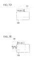
- the stage 8 is driven to the right (for example, the Y direction) by one-third of the image width of the standard-viewing-field image to acquire the edge-viewing-field image 302 ( Fig. 3B ), the stage 8 is driven downward (for example, the X direction) by one-third of the image height of the standard-viewing-field image and to the left by one-third of the image width thereof to acquire the edge-viewing-field image 303 ( Fig. 3C ), the stage 8 is driven downward by one-third of the image height of the standard-viewing-field image to acquire the edge-viewing-field image 304 ( Fig. 3D ), and finally the stage 8 is driven to the right by one-third of the image width of the standard-viewing-field image and downward by one-third of the image height thereof to acquire the edge-viewing-field image 305 ( Fig. 3E ).
- each of the edge-viewing-field images is acquired is arbitrary, and the relative positional relationship between the standard-viewing-field image 301 and the edge-viewing-field images 302 to 305 may be reversed.
- Width in Figs. 3A to 3E indicates the image width
- Height indicates the image height.
- step S205 specimen information is generated for the image to be corrected.
- an entered specimen name related to the image to be corrected is received by the specimen-information generating portion 15, and a histogram of the pixel values of the image to be corrected is generated.
- the image to be corrected is a color image having RGB elements
- a histogram is calculated for each color. Since the histogram is used as the specimen information indicating features of the specimen, instead of a histogram, it is possible to use information that indicates features of the image to be corrected, for example, the variance of the pixel values of the image to be corrected.
- step S206 the optical information and the specimen information at the time of acquiring the image to be corrected, which is input from the microscope 1, are stored in the correction-gain storage portion 5 in association with the correction gain of the image to be corrected, which was calculated in the preceding step.
- step S207 it is determined whether a plurality of correction gains associated with the optical information in common with the optical information of the image to be corrected are stored in the correction-gain storage portion 5. If, as a result of this determination, a plurality of such correction gains do not exist, in other words, if a single such correction gain is stored in the correction-gain storage portion 5, in step S211, shading correction is performed on the image to be corrected, using this correction gain.
- step S207 if it is determined that a plurality of correction gains having common optical information exist, the process proceeds to step S208, where histogram for the image to be corrected are generated. If specimen information has been generated in step S205 for the image to be corrected, a histogram has already been calculated, and therefore, the already calculated histogram is used as is.
- step S209 the histogram for the image to be corrected, which is calculated in step S208, and histograms related to the plurality of correction gains having common optical information, which are stored in the correction-gain storage portion 5, are compared by the correction-gain selecting portion 17, and their degree of similarly is determined.
- the determination of the degree of similarly of the histograms is performed, for example, as follows.
- the histogram of the image to be corrected defined as H ref and the histograms of the correction gains having common optical information, which are stored in the correction-gain storage portion, defined as H k
- the degree of similarity, d(H ref , H k ) between the histogram H ref of the image to be corrected and the histogram for the k-th correction gain from among the correction gains having common optical information, which are stored in the correction-gain storage portion can be determined by the crossover method represented by Equation (1) below.
- H ref (i) and H k (i) are the numbers of pixels having pixel value i, d(H ref , H k ), and it can be determined that the histogram for the correction gain that maximizes d(H ref , H k ) is most similar to the histogram for the image to be corrected. Therefore, the correction gain that maximizes d(H ref , H k ) serves as a candidate correction gain to be used in the shading correction.
- the calculation of the degree of similarity is not limited thereto, and a known method, such as correlation, ⁇ 2 , the Bhattacharyya distance or the like may be used.
- the correction-gain selecting portion 17 can present correction gain options to the user by displaying on the monitor 23 specimen names for all of the corrections gains having common optical information with that of the image to be corrected. When displaying these correction gains, they can be displayed in order of decreasing histogram similarity, or correction gains for which the histograms are most similar can be displayed as suggested candidates, on the basis of the results of comparing the histograms.
- step S211 the correction gain selected in step S210 is used to perform shading correction of the image to be corrected.
- the user may make a selection from the displayed candidates, or a correction gain input via a keyboard 24 or mouse 25 may be selected.
- the correction-gain selecting portion 17 can select, from the stored correction gains, the correction gain to be used in shading correction.
- the correction gain that maximizes the degree of similarity of the histograms serving as the specimen information can be selected from this plurality of correction gains by the correction-gain selecting portion 17 as the correction gain to be used in shading correction of the image to be corrected.
- the procedure in the case when the correction gain to be used in shading correction is selected from the plurality of correction gains stored in the correction-gain storage portion by the correction-gain selecting portion 17 differs from that in the microscope system according to the first embodiment described above.
- the correction-gain selecting portion 17 performs shading correction of the image to be corrected using the plurality of correction gains having common optical information and selects the correction gain to be used in the shading correction of the image to be corrected on the basis of the correction results thereof.
- step S301 the image-acquisition portion 10, which receives an image acquisition instruction from the computer 3 via the image-acquisition control portion 21, acquires the standard-viewing-field image shown in Fig. 3A as the image to be corrected, and the image-acquisition control portion 21 performs development processing in and outputs the result to the image processing portion 4.
- step S302 the computer 3 determines whether a correction gain having optical information in common with that of the image to be corrected is stored in the correction-gain storage portion 5. If a correction gain having common optical information exists, the process proceeds to step S303, and in step S303, it is determined whether a correction gain should be newly calculated for the image to be corrected.
- step S302 In the case where, in step S302, a correction gain having common optical information does not exist, or in the case where, in step S303, there is an instruction from the computer 3 to calculate a correction gain, for example, an instruction given by a user, then in step S304, calculation of a correction gain for the image to be corrected is performed.
- step S303 in the case where there is no instruction from the computer 3 to calculate a correction gain, the process proceeds to step S307, described below.
- the calculation of the correction gain is performed using the same procedure as the calculation of the correction gain in the first embodiment described above.
- step S305 specimen information is generated for the image to be corrected.
- an entered specimen name related to the image to be corrected is received by the specimen-information generating portion 15.
- step S306 optical information at the time of acquiring the image to be corrected, which is input from the microscope 1, and specimen information are stored in the correction-gain storage portion 5 in association with the correction gain for the image to be corrected, which is calculated in the previous step.
- step S307 it is determined whether a plurality of correction gains associated with the optical information in common with the optical information of the image to be corrected are stored in the correction-gain storage portion 5. If, as a result of this determination, a plurality of such correction gains do not exist, in other words, if a single such correction gain is stored in the correction-gain storage portion 5, in step S312, shading correction is performed on the image to be corrected, using this correction gain.
- step S307 if it is determined that a plurality of correction gains having common optical information do exist, the process proceeds to step S308, where shading correction of the image to be corrected is performed using all of the correction gains having common optical information.
- step S309 the correction-gain selecting portion 17 applies a low-pass filter to each of the images subjected to shading correction.
- the low-pass filter it is possible to use, for example, an averaging filter expressed by Equation (2) below.
- f(x,y) is the pixel value at coordinates (x,y) after applying the averaging filter
- I(x,y) is the pixel value at coordinates (x,y)
- M and N are the filter size in the x-direction and the filter size in the y-direction, respectively.
- the low-pass filter is not limited to an averaging filter, and a known method may be used, such as a Gaussian filter, or applying a low-pass filter to the results of Fourier transformation, followed by inverse Fourier transformation.
- step S310 the variance of a diagonal line profile in each image subjected to low-pass filter processing is calculated by the correction-gain selecting portion 17, and in step S311, the correction gain having the smallest variance is selected as a candidate correction gain for eventual use in the shading correction.
- step S312 shading correction of the image to be corrected is performed using the correction gain selected by the correction-gain selecting portion 17.
- the correction-gain selecting portion 17 can select, from the stored correction gains, a correction gain for use in shading correction.
- a correction gain for use in the shading correction of the image to be corrected can be selected from this plurality of correction gains by the correction-gain selecting portion 17, based on the results of shading correction with the plurality of correction gains, in other words, based on the variances of the respective line profiles of the images according to the results of the shading correction.
Landscapes
- Engineering & Computer Science (AREA)
- Physics & Mathematics (AREA)
- Multimedia (AREA)
- General Physics & Mathematics (AREA)
- Chemical & Material Sciences (AREA)
- Analytical Chemistry (AREA)
- Optics & Photonics (AREA)
- Computer Vision & Pattern Recognition (AREA)
- Signal Processing (AREA)
- Microscoopes, Condenser (AREA)
- Theoretical Computer Science (AREA)
- Studio Devices (AREA)
Abstract
Description
- The present invention relates to a microscope system.
- There is a known virtual slide in which a plurality of sets of partial image data formed by acquiring images of parts of a specimen on a slide glass with a microscope at high resolution are connected together to obtain image data of the entire specimen, and this image data is displayed on a PC display or the like and can be observed as a microscope image.
- In the case where an image is acquired in a microscope, shading occurs, which means brightness variations that arise due to variations in the light source, nonuniformity in the optical system, variations in the image-acquisition device and so forth. Shading becomes darker farther from the optical axis, and therefore, when a plurality of sets of partial image data are connected, as with a virtual slide, unnatural boundaries occur at the boundary areas in each set of partial image data, and the shading itself appears to be a pattern on the specimen.
- In addition, shading has the property that it changes depending on the reflection and scattering characteristics of the specimen and therefore must be corrected for each specimen according to the characteristics of that specimen.
- Therefore, there are microscope systems that prepare a correction gain, which is a shading correction value, in advance and perform shading correction on the basis of this correction gain. As an example of such a microscope system, Patent Literature 1 discloses an apparatus in which a correction gain is obtained on the basis of a change in brightness of an image in which a prescribed location on the specimen is acquired at the center of the viewing field and an image in which that same location is acquired at the edge of the viewing field, and shading correction is performed on the basis of the thus-obtained correction gain.
- Japanese Unexamined Patent Application, Publication No.
2013-257422 - However, with the microscope system disclosed in Patent Literature 1, to obtain the correction gain, it is necessary to repeat the image acquisition a plurality of times while moving the location on the specimen relative to the optical system. Therefore, a correction gain is obtained each time the specimen to be observed is changed, and shading correction thus takes a long time.
- The present invention has been conceived in light of the above circumstances, and an object thereof is to perform the desired shading correction in a more simple manner.
- In order to realize the above object, the present invention provides the following solutions.
- An aspect of the present invention provides a microscope system including a microscope that acquires an optical image of a specimen to obtain an image; a correction-gain calculating portion that calculates a correction gain for performing shading correction of the image obtained by the microscope; a correction-gain storage portion that stores specimen information indicating features of the specimen and optical information at the time of obtaining the image in association with the correction gain calculated by the correction-gain calculating portion; a correction-gain selecting portion that selects the correction gain for use when performing the shading correction of the image to be corrected, which is obtained by the microscope; and a correction portion that performs the shading correction of the image to be corrected, on the basis of the correction gain selected by the correction-gain selecting portion, wherein, in a case where a plurality of the correction gains associated with optical information in common with the optical information at the time of obtaining the image to be corrected are stored in the correction-gain storage portion, on the basis of the specimen information or correction results obtained by performing the shading correction with the plurality of correction gains, the correction-gain selecting portion selects, from the plurality of correction gains associated with the optical information in common with the optical information at the time of obtaining the image to be corrected, the correction gain to be used in the shading correction of the image to be corrected.
- With this aspect, optical images of the specimen are acquired by the microscope to obtain an image. For the obtained image, a correction gain to be used in shading correction is calculated by the correction-gain calculating portion, and the calculated correction gain is stored in the correction-gain storage portion in association with the optical information at the time of obtaining the image and specimen information. In the case where a correction gain associated with optical information in common with that of the image to be corrected, which is obtained by the microscope, is stored in the correction-gain storage portion, it is possible to select, from the correction gains stored in the correction-gain storage portion, a correction gain to be used in shading correction. Here, in the case where a plurality of correction gains associated with optical information in common with that of the optical information at the time of obtaining the image to be corrected are stored, a correction gain to be used in shading correction of the image to be corrected is selected by the correction-gain selecting portion from among this plurality of correction gains on the basis of the specimen information or the results of the shading correction using the plurality of correction gains.
- Therefore, when optical images of the specimen are acquired by the microscope to obtain the image to be corrected, it is not always necessary to calculate a correction gain each time, and it is possible to use a correction gain that is stored in the correction-gain storage portion. In addition, in the case where there are a plurality of correction gains to be used, by selecting the most appropriate correction gain, it is possible to perform shading correction simply and effectively.
- In the above-described aspect of the invention, the microscope may include a stage on which the specimen is mounted; an optical system that forms an image of the specimen; a driving portion that moves the specimen and the optical system relative to each other by driving at least one of the optical system and the stage; and an image-acquisition portion that acquires a standard-viewing-field image, which is an image of a prescribed viewing-field range of the specimen, and that relatively moves, with the driving portion, the position of the specimen with respect to the optical system to acquire a plurality of edge-viewing-field images, which include a prescribed region inside the prescribed viewing-field range and which are images of edge-viewing-field ranges that each differ from the prescribed viewing-field range, wherein the correction-gain calculating portion may calculate a correction gain of each pixel in the standard-viewing-field image on the basis of the standard-viewing-field image and the edge-viewing-field images.
- By doing so, by acquiring an image of a region where shading at the center of the image does not become a problem and a plurality of edge-viewing-field images, it is possible to calculate a preferable correction gain on the basis of brightness variations.
- In the above-described aspect of the invention, from among the plurality of correction gains associated with optical information in common with optical information at the time of obtaining the image to be corrected, the correction-gain selecting portion may select, on the basis of a degree of similarity between the specimen information at the time of calculation of the correction gains and specimen information of the image to be corrected, the correction gain to be used in shading correction of the image to be corrected.
- By doing so, it is possible to select the optimal correction gain for the shading correction of the image to be corrected.
- In the above-described aspect of the invention, from among the plurality of correction gains associated with the optical information in common with the optical information at the time of obtaining the image to be corrected, the correction-gain selecting portion may select a correction gain that maximizes the shading correction effect as the correction gain to be used in the shading correction of the image to be corrected.
- By doing so, it is possible to select the optimal correction gain for shading correction of the image to be corrected.
- The above-described aspect of the invention may further include a display portion that displays candidates of correction gains to be used in shading correction of the image to be corrected, from among the plurality of correction gains associated with the optical information in common with the optical information at the time of obtaining the image to be corrected.
- By doing so, it is possible to present the user with candidate correction gains for use in the shading correction.
- The present invention affords an advantage in that the desired shading correction can be performed more simply.
-
- {
Fig. 1} Fig. 1 is a block diagram showing the overall configuration of a microscope system according to a first embodiment of the present invention. - {
Fig. 2} Fig. 2 is a flowchart of shading correction in the microscope system according to the first embodiment of the present invention. - {
Fig. 3A} Fig. 3A is an explanatory diagram showing an example of a standard-viewing-field image and an edge-viewing-field image. - {
Fig. 3B} Fig. 3B is an explanatory diagram showing an example of a standard-viewing-field image and an edge-viewing-field image. - {
Fig. 3C} Fig. 3C is an explanatory diagram showing an example of a standard-viewing-field image and an edge-viewing-field image. - {
Fig. 3D} Fig. 3D is an explanatory diagram showing an example of a standard-viewing-field image and an edge-viewing-field image. - {
Fig. 3E} Fig. 3E is an explanatory diagram showing an example of a standard-viewing-field image and an edge-viewing-field image. - {
Fig. 4} Fig. 4 is a flowchart of shading correction in a microscope system according to a second embodiment of the present invention. - A microscope system according to a first embodiment of the present invention will be described below with reference to the drawings.
- As shown in
Fig. 1 , the microscope system includes a microscope 1 that obtains an image by acquiring an optical image of a specimen A, acontrol portion 2 that controls the microscope 1, and a computer (PC) 3 that is connected to thecontrol portion 2 and that functions as an image processing portion that performs prescribed processing on the image obtained by the microscope 1. - In the microscope 1, illumination light emitted from a
light source 7 illuminates a specimen A mounted on astage 8 via ahalf mirror 6, an optical image of the specimen A is formed on an image-acquisition surface of an image-acquisition portion 10 via anobjective lens 9 and an image-forming lens which is not illustrated (optical system), and the image-acquisition portion 10 obtains this optical image as an image. - A
motor 11 is provided on thestage 8 of the microscope 1, and by driving thismotor 11 with a driving-mechanism control portion 20, the specimen A mounted on thestage 8 is moved relative to the optical system formed of theobjective lens 9 and the image-forming lens. - The
stage 8 is driven in directions perpendicular to the optical axis of the objective lens 9 (two directions, for example, the X direction and the Y direction) by driving themotor 11 with the driving-mechanism control portion 20, and as a result, the specimen A and the optical system, and thus the image-acquisition portion 10, can be moved relative to each other. By moving the specimen A and the image-acquisition portion 10 relative to each other, the position that is illuminated by the light from thelight source 7 and the image formed on the image-acquisition device in the image-acquisition portion 10 move. - The image-
acquisition portion 10, which is a digital camera that is provided with an image-acquisition device such as a CCD, a CMOS device, or the like, acquires the optical image formed thereon, and outputs the acquired image to an image-acquisition control portion 21 in thecontrol portion 2 in the form of a digital image. The image-acquisition portion 10 is controlled by the image-acquisition control portion 21. The image-acquisition control portion 21 sets image-acquisition conditions in the image-acquisition portion 10, such as an exposure time, ISO sensitivity, and the like, in accordance with an instruction from thecomputer 3, to be described later, performs development processing on the acquired image, and outputs the image that has been subjected to development processing to thecomputer 3. - The
control portion 2 includes the image-acquisition control portion 21, which controls the image-acquisition portion 10, and a driving-mechanism control portion 20 that controls thestage 8; the image-acquisition portion 10 is controlled by the image-acquisition control portion 21, and thestage 8 is controlled by the driving-mechanism control portion 20 so that a prescribed number of images are acquired at prescribed positions. More specifically, thecontrol portion 2 controls the image-acquisition portion 10 and thestage 8 to acquire a standard-viewing-field image that serves as the image to be corrected and, when calculating the correction gain, to obtain a plurality of edge-viewing-field images with which a prescribed region at the center of the standard-viewing-field image overlaps and which are images of different viewing-field ranges, and outputs these obtained images to theimage processing portion 4. - The
computer 3, which includes a CPU (central processing unit) serving as a computational portion, performs prescribed image processing on the images input thereto from the image-acquisition control portion 21 and controls thecontrol portion 2, amonitor 23, akeyboard 24, and amouse 25, which are connected to thecomputer 3, in a unified manner. A general-purpose or special-purpose computer can be used as thecomputer 3, and the CPU executes image processing in which prescribed processing is performed on the image of the specimen A obtained by the image-acquisition portion 10, as well as various control programs. Thecomputer 3 includes theimage processing portion 4, which serves as a processing portion that is realized by the CPU loading and executing a prescribed program, and a correction-gain storage portion 5 that is connected to theimage processing portion 4. - The
image processing portion 4 includes a specimen-information generating portion 15, a correction-gain calculating portion 16, a correction-gain selecting portion 17, and ashading correcting portion 18. - As specimen information, the specimen-
information generating portion 15 generates information indicating features of the image, such as a specimen name related to the image acquired by the image-acquisition portion 10, a histogram of pixel values of that image, the variance of the pixel values, and so forth. - The correction-
gain calculating portion 16 calculates a correction gain for performing shading correction on the image obtained by the microscope 1. Calculation of the correction gain in the correction-gain calculating portion 16 is performed in the case where a correction gain suitable for shading correction of the image to be corrected does not exist in the correction-gain storage portion 5, or in the case where there is an instruction from thecomputer 3 to obtain a correction gain again. - The correction-
gain calculating portion 16 stores the calculated correction gain in the correction-gain storage portion 5 in association with optical information at the time of obtaining the image for which the correction gain was calculated and the specimen information generated by the specimen-information generating portion 15. The optical information includes information related to the optical conditions at the time of obtaining the image, such as the microscopy method used in the microscope 1, the type of light source, the type of objective lens, and, in the case where the image-acquisition portion 10 is provided with a camera adapter or the like, the magnification thereof, at the time of acquiring the image for which this correction gain was calculated. Therefore, each time a correction gain is newly calculated by the correction-gain calculating portion 16, the correction-gain storage portion 5 stores the calculated correction gain, together with the optical information related to that image and the specimen information of that image, which is generated by the specimen-information generating portion 15, in association with each other. The stored correction gains serve as candidates at the time of correction gain selection performed by a correction-gain selecting portion 17, described below. - The correction-
gain selecting portion 17 selects the correction gain to be used when performing shading correction on the image to be corrected, which is obtained by the microscope 1. More specifically, in the case where a plurality of correction gains that are associated with optical information in common with the optical information at the time of obtaining the image to be corrected are stored in the correction-gain storage portion 5, from this plurality of correction gains, the correction-gain selecting portion 17 selects, on the basis of the specimen information, a correction gain to be used in shading correction of the image to be corrected. In this embodiment, the correction gain to be used in shading correction of the image to be corrected is selected by using a histogram of the pixel values in the image as the specimen information. - The term "having common optical information" includes, of course, the case where the optical information of the image to be corrected and all of the optical information associated with the correction gains stored in the correction-gain storage portion match, and also the case where they partially match, for example, where only the information related to the microscopy method and objective lens match.
- The
shading correcting portion 18 performs shading correction on the image to be corrected, in accordance with the correction gain selected by the correction-gain selecting portion 17, and obtains an image in which shading has been corrected. - The flow of shading correction performed by the thus-configured microscope system will be described below by following the flowchart in
Fig. 2 . - In step S201, the image-
acquisition control portion 21 gives an instruction to acquire an optical image of the specimen A to the image-acquisition portion 10 according to an instruction from thecomputer 3, and upon receiving this instruction, the image-acquisition portion 10 acquires a standard-viewing-field image shown inFig. 3A as the image to be corrected, and the image-acquisition control portion 21 performs development processing and outputs the result to theimage processing portion 4. - In Step S202, the
computer 3 determines whether there is a correction gain stored in the correction-gain storage portion 5 in association with the optical information in common with the optical information at the time of acquiring the image to be corrected, in other words, a correction gain having optical information in common with that of the image to be corrected. If a correction gain having common optical information exists, the process proceeds to step S203, and in step S203, it is determined whether or not to newly calculate a correction gain for the image to be corrected. - In the case where, in step S202, a correction gain having common optical information does not exist, or in the case where, in step S203, there is an instruction from the
computer 3 to calculate a correction gain, for example, an instruction given by a user, then in step S204, calculation of a correction gain for the image to be corrected is performed. On the other hand, in step S203, in the case where there is no instruction from thecomputer 3 to calculate a correction gain, the process proceeds to step S207, described below. - In step S204, correction gain calculation is performed, for example, as follows. The
stage 8 is driven by the driving-mechanism control portion 20 to make the specimen A and the image-acquisition portion 10 move relative to each other, and a standard-viewing-field image, which is the image to be corrected, and a prescribed region inside this standard-viewing-field image are overlapped while forming different viewing-field ranges, so that a plurality of edge-viewing-field images are acquired. As the edge-viewing-field images, for example, a configuration in which four images are acquired while shifting them with respect to the standard-viewing-field image by about 1/3 of the image size is possible. - Specifically, in
Figs. 3A to 3E , a standard-viewing-field image 301 and edge-viewing-field images field images Figs. 3B to 3E , the standard-viewing-field image 301 is indicated by the broken line. - In other words, after the standard-viewing-
field image 301 is acquired (Fig. 3A ), thestage 8 is driven to the right (for example, the Y direction) by one-third of the image width of the standard-viewing-field image to acquire the edge-viewing-field image 302 (Fig. 3B ), thestage 8 is driven downward (for example, the X direction) by one-third of the image height of the standard-viewing-field image and to the left by one-third of the image width thereof to acquire the edge-viewing-field image 303 (Fig. 3C ), thestage 8 is driven downward by one-third of the image height of the standard-viewing-field image to acquire the edge-viewing-field image 304 (Fig. 3D ), and finally thestage 8 is driven to the right by one-third of the image width of the standard-viewing-field image and downward by one-third of the image height thereof to acquire the edge-viewing-field image 305 (Fig. 3E ). - Note that the order in which each of the edge-viewing-field images is acquired is arbitrary, and the relative positional relationship between the standard-viewing-
field image 301 and the edge-viewing-field images 302 to 305 may be reversed. Width inFigs. 3A to 3E indicates the image width, and Height indicates the image height. Based on the standard-viewing-field image and the edge-viewing-field images acquired in this way, there is almost no shading at the center of the viewing field, and therefore, the correction gain is calculated based on the ratio of the brightnesses of the images in which the center and the peripheries overlap. - Next, in step S205, specimen information is generated for the image to be corrected. In other words, an entered specimen name related to the image to be corrected is received by the specimen-
information generating portion 15, and a histogram of the pixel values of the image to be corrected is generated. In the case where the image to be corrected is a color image having RGB elements, a histogram is calculated for each color. Since the histogram is used as the specimen information indicating features of the specimen, instead of a histogram, it is possible to use information that indicates features of the image to be corrected, for example, the variance of the pixel values of the image to be corrected. - In step S206, the optical information and the specimen information at the time of acquiring the image to be corrected, which is input from the microscope 1, are stored in the correction-
gain storage portion 5 in association with the correction gain of the image to be corrected, which was calculated in the preceding step. - In step S207, it is determined whether a plurality of correction gains associated with the optical information in common with the optical information of the image to be corrected are stored in the correction-
gain storage portion 5. If, as a result of this determination, a plurality of such correction gains do not exist, in other words, if a single such correction gain is stored in the correction-gain storage portion 5, in step S211, shading correction is performed on the image to be corrected, using this correction gain. - On the other hand, in the determination at step S207, if it is determined that a plurality of correction gains having common optical information exist, the process proceeds to step S208, where histogram for the image to be corrected are generated. If specimen information has been generated in step S205 for the image to be corrected, a histogram has already been calculated, and therefore, the already calculated histogram is used as is.
- In step S209, the histogram for the image to be corrected, which is calculated in step S208, and histograms related to the plurality of correction gains having common optical information, which are stored in the correction-
gain storage portion 5, are compared by the correction-gain selecting portion 17, and their degree of similarly is determined. The determination of the degree of similarly of the histograms is performed, for example, as follows. - With the histogram of the image to be corrected defined as Href and the histograms of the correction gains having common optical information, which are stored in the correction-gain storage portion, defined as Hk, the degree of similarity, d(Href, Hk), between the histogram Href of the image to be corrected and the histogram for the k-th correction gain from among the correction gains having common optical information, which are stored in the correction-gain storage portion, can be determined by the crossover method represented by Equation (1) below.
- [Equation 1]

- Here, i is the pixel value, N is the maximum pixel value, and Href(i) and Hk(i) are the numbers of pixels having pixel value i, d(Href, Hk), and it can be determined that the histogram for the correction gain that maximizes d(Href, Hk) is most similar to the histogram for the image to be corrected. Therefore, the correction gain that maximizes d(Href, Hk) serves as a candidate correction gain to be used in the shading correction.
- The calculation of the degree of similarity is not limited thereto, and a known method, such as correlation, χ2, the Bhattacharyya distance or the like may be used.
- The correction-
gain selecting portion 17 can present correction gain options to the user by displaying on themonitor 23 specimen names for all of the corrections gains having common optical information with that of the image to be corrected. When displaying these correction gains, they can be displayed in order of decreasing histogram similarity, or correction gains for which the histograms are most similar can be displayed as suggested candidates, on the basis of the results of comparing the histograms. - In step S211, the correction gain selected in step S210 is used to perform shading correction of the image to be corrected. The user may make a selection from the displayed candidates, or a correction gain input via a
keyboard 24 ormouse 25 may be selected. - Thus, with the microscope system according to this embodiment, in the case where correction gains associated with the optical information in common with that of the image to be corrected, which is obtained by the microscope 1, are stored in the correction-
gain storage portion 5, the correction-gain selecting portion 17 can select, from the stored correction gains, the correction gain to be used in shading correction. In particular, in the case where a plurality of correction gains associated with optical information in common with the optical information at the time of obtaining the image to be corrected are stored, the correction gain that maximizes the degree of similarity of the histograms serving as the specimen information can be selected from this plurality of correction gains by the correction-gain selecting portion 17 as the correction gain to be used in shading correction of the image to be corrected. - Therefore, when an optical image of the specimen is acquired by the microscope to obtain the image to be corrected, it is not always necessary to calculate the correction gain each time, and it is possible to use a correction gain that is stored in the correction-
gain storage portion 5. In addition, in the case where there are a plurality of correction gain candidates to be used, by selecting the most appropriate correction gain, it is possible to perform shading correction simply and effectively. - In the following, a second embodiment of the present invention will be described.
- In the microscope system according to this embodiment, the procedure in the case when the correction gain to be used in shading correction is selected from the plurality of correction gains stored in the correction-gain storage portion by the correction-
gain selecting portion 17 differs from that in the microscope system according to the first embodiment described above. - Specifically, in the microscope system according to this embodiment, in the case where a plurality of correction gains associated with optical information in common with the optical information at the time of obtaining the image to be corrected are stored, the correction-
gain selecting portion 17 performs shading correction of the image to be corrected using the plurality of correction gains having common optical information and selects the correction gain to be used in the shading correction of the image to be corrected on the basis of the correction results thereof. - Since the microscope system according to this embodiment has substantially the same configuration as the first embodiment described above, a description of each structure is omitted, and the flow of shading correction will be described by following the flowchart in
Fig. 4 . - In step S301, the image-
acquisition portion 10, which receives an image acquisition instruction from thecomputer 3 via the image-acquisition control portion 21, acquires the standard-viewing-field image shown inFig. 3A as the image to be corrected, and the image-acquisition control portion 21 performs development processing in and outputs the result to theimage processing portion 4. - In step S302, the
computer 3 determines whether a correction gain having optical information in common with that of the image to be corrected is stored in the correction-gain storage portion 5. If a correction gain having common optical information exists, the process proceeds to step S303, and in step S303, it is determined whether a correction gain should be newly calculated for the image to be corrected. - In the case where, in step S302, a correction gain having common optical information does not exist, or in the case where, in step S303, there is an instruction from the
computer 3 to calculate a correction gain, for example, an instruction given by a user, then in step S304, calculation of a correction gain for the image to be corrected is performed. On the other hand, in step S303, in the case where there is no instruction from thecomputer 3 to calculate a correction gain, the process proceeds to step S307, described below. The calculation of the correction gain is performed using the same procedure as the calculation of the correction gain in the first embodiment described above. - Next, in step S305, specimen information is generated for the image to be corrected. In other words, an entered specimen name related to the image to be corrected is received by the specimen-
information generating portion 15. - In step S306, optical information at the time of acquiring the image to be corrected, which is input from the microscope 1, and specimen information are stored in the correction-
gain storage portion 5 in association with the correction gain for the image to be corrected, which is calculated in the previous step. - In step S307, it is determined whether a plurality of correction gains associated with the optical information in common with the optical information of the image to be corrected are stored in the correction-
gain storage portion 5. If, as a result of this determination, a plurality of such correction gains do not exist, in other words, if a single such correction gain is stored in the correction-gain storage portion 5, in step S312, shading correction is performed on the image to be corrected, using this correction gain. - On the other hand, in the determination in step S307, if it is determined that a plurality of correction gains having common optical information do exist, the process proceeds to step S308, where shading correction of the image to be corrected is performed using all of the correction gains having common optical information.
- In step S309, the correction-
gain selecting portion 17 applies a low-pass filter to each of the images subjected to shading correction. As the low-pass filter, it is possible to use, for example, an averaging filter expressed by Equation (2) below. - [Equation 2]

- Here, f(x,y) is the pixel value at coordinates (x,y) after applying the averaging filter, I(x,y) is the pixel value at coordinates (x,y), and M and N are the filter size in the x-direction and the filter size in the y-direction, respectively. The filter sizes should be set to sufficiently large sizes relative to the image size; for example, it is possible to set N = M = 300. The low-pass filter is not limited to an averaging filter, and a known method may be used, such as a Gaussian filter, or applying a low-pass filter to the results of Fourier transformation, followed by inverse Fourier transformation.
- Next, in step S310, the variance of a diagonal line profile in each image subjected to low-pass filter processing is calculated by the correction-
gain selecting portion 17, and in step S311, the correction gain having the smallest variance is selected as a candidate correction gain for eventual use in the shading correction. - In step S312, shading correction of the image to be corrected is performed using the correction gain selected by the correction-
gain selecting portion 17. - With the microscope system according to this embodiment, in the case where correction gains associated with optical information in common with that of the image to be corrected, which is obtained by the microscope 1, are stored in the correction-
gain storage portion 5, the correction-gain selecting portion 17 can select, from the stored correction gains, a correction gain for use in shading correction. In particular, in the case where a plurality of correction gains associated with optical information in common with the optical information at the time of obtaining the image to be corrected are stored, a correction gain for use in the shading correction of the image to be corrected can be selected from this plurality of correction gains by the correction-gain selecting portion 17, based on the results of shading correction with the plurality of correction gains, in other words, based on the variances of the respective line profiles of the images according to the results of the shading correction. - Therefore, when acquiring optical images of the specimen with the microscope to obtain the image to be corrected, it is not always necessary to calculate the correction gain each time, and it is possible to use a correction gain that is stored in the correction-
gain storage portion 5. In addition, in the case where there are a plurality of correction gain candidates to be used, by selecting the most appropriate correction gain, it is possible to perform shading correction simply and effectively. -
- 1
- Microscope
- 2
- Control portion
- 3
- Computer (PC)
- 4
- Image processing portion
- 15
- Specimen-information generating portion
- 16
- Correction-gain calculating portion
- 17
- Correction-gain selecting portion
- 18
- Shading correcting portion
- 20
- Driving-mechanism control portion
- 21
- Image-acquisition control portion
Claims (5)
- A microscope system comprising:a microscope that acquires an optical image of a specimen to obtain an image;a correction-gain calculating portion that calculates a correction gain for performing shading correction of the image obtained by the microscope;a correction-gain storage portion that stores specimen information indicating features of the specimen and optical information at the time of obtaining the image in association with the correction gain calculated by the correction-gain calculating portion;a correction-gain selecting portion that selects the correction gain for use when performing the shading correction of the image to be corrected, which is obtained by the microscope; anda correction portion that performs the shading correction of the image to be corrected, on the basis of the correction gain selected by the correction-gain selecting portion,wherein, in a case where a plurality of the correction gains associated with optical information in common with the optical information at the time of obtaining the image to be corrected are stored in the correction-gain storage portion,on the basis of the specimen information or correction results obtained by performing the shading correction with the plurality of correction gains, the correction-gain selecting portion selects, from the plurality of correction gains associated with the optical information in common with the optical information at the time of obtaining the image to be corrected, the correction gain to be used in the shading correction of the image to be corrected.
- A microscope system according to Claim 1, wherein the microscope includes
a stage on which the specimen is mounted;
an optical system that forms an image of the specimen;
a driving portion that moves the specimen and the optical system relative to each other by driving at least one of the optical system and the stage; and
an image-acquisition portion that acquires a standard-viewing-field image, which is an image of a prescribed viewing-field range of the specimen, and that relatively moves, with the driving portion, the position of the specimen with respect to the optical system to acquire a plurality of edge-viewing-field images, which include a prescribed region inside the prescribed viewing-field range and which are images of edge-viewing-field ranges that each differ from the prescribed viewing-field range,
wherein the correction-gain calculating portion calculates a correction gain of each pixel in the standard-viewing-field image on the basis of the standard-viewing-field image and the edge-viewing-field images. - A microscope system according to Claim 1 or 2, wherein, from among the plurality of correction gains associated with optical information in common with optical information at the time of obtaining the image to be corrected, the correction-gain selecting portion selects, on the basis of a degree of similarity between the specimen information at the time of calculation of the correction gains and specimen information of the image to be corrected, the correction gain to be used in shading correction of the image to be corrected.
- A microscope system according to Claim 1 or 2, wherein, from among the plurality of correction gains associated with the optical information in common with the optical information at the time of obtaining the image to be corrected, the correction-gain selecting portion selects a correction gain that maximizes the shading correction effect as the correction gain to be used in the shading correction of the image to be corrected.
- A microscope system according to any one of claims 1 to 4, further comprising a display portion that displays candidates of correction gains to be used in shading correction of the image to be corrected, from among the plurality of correction gains associated with the optical information in common with the optical information at the time of obtaining the image to be corrected.
Applications Claiming Priority (1)
| Application Number | Priority Date | Filing Date | Title |
|---|---|---|---|
| JP2014106125A JP6284428B2 (en) | 2014-05-22 | 2014-05-22 | Microscope system |
Publications (1)
| Publication Number | Publication Date |
|---|---|
| EP2947495A1 true EP2947495A1 (en) | 2015-11-25 |
Family
ID=53002537
Family Applications (1)
| Application Number | Title | Priority Date | Filing Date |
|---|---|---|---|
| EP15164432.5A Withdrawn EP2947495A1 (en) | 2014-05-22 | 2015-04-21 | Microscope system with computer for shading correction |
Country Status (3)
| Country | Link |
|---|---|
| US (1) | US9778451B2 (en) |
| EP (1) | EP2947495A1 (en) |
| JP (1) | JP6284428B2 (en) |
Families Citing this family (1)
| Publication number | Priority date | Publication date | Assignee | Title |
|---|---|---|---|---|
| JP2024030022A (en) * | 2022-08-23 | 2024-03-07 | 国立研究開発法人情報通信研究機構 | Microscope image correction method and microscope image correction program |
Citations (4)
| Publication number | Priority date | Publication date | Assignee | Title |
|---|---|---|---|---|
| US20070066967A1 (en) * | 2003-10-21 | 2007-03-22 | Leica Microsystems Cms Gmbh | Method for automatic production of laser cutting lines in laser micro-dissection |
| JP2013156279A (en) * | 2012-01-26 | 2013-08-15 | Olympus Corp | Image processing device and microscope system |
| US8577171B1 (en) * | 2006-07-31 | 2013-11-05 | Gatan, Inc. | Method for normalizing multi-gain images |
| US20130329033A1 (en) * | 2012-06-12 | 2013-12-12 | Olympus Corporation | Microscope system |
Family Cites Families (11)
| Publication number | Priority date | Publication date | Assignee | Title |
|---|---|---|---|---|
| JP5161052B2 (en) * | 2008-12-04 | 2013-03-13 | オリンパス株式会社 | Microscope system, specimen observation method and program |
| US6711283B1 (en) * | 2000-05-03 | 2004-03-23 | Aperio Technologies, Inc. | Fully automatic rapid microscope slide scanner |
| KR100911378B1 (en) * | 2007-02-23 | 2009-08-10 | 삼성전자주식회사 | Lens correction method and lens correction device |
| JP2009162974A (en) * | 2008-01-07 | 2009-07-23 | Olympus Corp | Microscope system and its control method |
| US8340453B1 (en) * | 2008-08-29 | 2012-12-25 | Adobe Systems Incorporated | Metadata-driven method and apparatus for constraining solution space in image processing techniques |
| JP5911296B2 (en) * | 2011-12-22 | 2016-04-27 | オリンパス株式会社 | Image processing apparatus, imaging apparatus, microscope system, image processing method, and image processing program |
| JP6004221B2 (en) * | 2012-03-22 | 2016-10-05 | 三星電子株式会社Samsung Electronics Co.,Ltd. | Image processing device |
| JP5991850B2 (en) * | 2012-05-11 | 2016-09-14 | オリンパス株式会社 | Microscope equipment |
| JP5996462B2 (en) * | 2013-03-13 | 2016-09-21 | オリンパス株式会社 | Image processing apparatus, microscope system, and image processing method |
| JP6346431B2 (en) * | 2013-11-13 | 2018-06-20 | 三星電子株式会社Samsung Electronics Co.,Ltd. | Image processing apparatus and image processing method |
| JP6276564B2 (en) * | 2013-11-18 | 2018-02-07 | 三星電子株式会社Samsung Electronics Co.,Ltd. | Image processing apparatus and image processing method |
-
2014
- 2014-05-22 JP JP2014106125A patent/JP6284428B2/en active Active
-
2015
- 2015-04-21 EP EP15164432.5A patent/EP2947495A1/en not_active Withdrawn
- 2015-04-27 US US14/696,832 patent/US9778451B2/en not_active Expired - Fee Related
Patent Citations (5)
| Publication number | Priority date | Publication date | Assignee | Title |
|---|---|---|---|---|
| US20070066967A1 (en) * | 2003-10-21 | 2007-03-22 | Leica Microsystems Cms Gmbh | Method for automatic production of laser cutting lines in laser micro-dissection |
| US8577171B1 (en) * | 2006-07-31 | 2013-11-05 | Gatan, Inc. | Method for normalizing multi-gain images |
| JP2013156279A (en) * | 2012-01-26 | 2013-08-15 | Olympus Corp | Image processing device and microscope system |
| US20130329033A1 (en) * | 2012-06-12 | 2013-12-12 | Olympus Corporation | Microscope system |
| JP2013257422A (en) | 2012-06-12 | 2013-12-26 | Olympus Corp | Microscope system |
Also Published As
| Publication number | Publication date |
|---|---|
| JP6284428B2 (en) | 2018-02-28 |
| JP2015222310A (en) | 2015-12-10 |
| US9778451B2 (en) | 2017-10-03 |
| US20150338632A1 (en) | 2015-11-26 |
Similar Documents
| Publication | Publication Date | Title |
|---|---|---|
| US20230410493A1 (en) | Image processing system, image processing method, and program storage medium | |
| US20200043157A1 (en) | Inspection Apparatus, Inspection Method, And Program | |
| JP5804220B1 (en) | Image processing apparatus and image processing program | |
| EP3444584B1 (en) | Inspecting device and inspecting method | |
| CN111598913B (en) | Image segmentation method and system based on robot vision | |
| US9482855B2 (en) | Microscope system | |
| CN117670886B (en) | Display screen defect detection method, device, equipment and storage medium | |
| CN113269728B (en) | Visual edge-tracking method, device, readable storage medium and program product | |
| JPWO2017169782A1 (en) | Distance image processing device, distance image acquisition device, and distance image processing method | |
| CN111369513A (en) | Anomaly detection method, device, terminal device and storage medium | |
| US12249129B2 (en) | Machine learning method and information processing apparatus for machine learning | |
| US8712164B2 (en) | Image processing apparatus, image registering method, program causing computer to execute image registering method, and recording medium in which program is recorded | |
| JP6479178B2 (en) | Image processing apparatus, imaging apparatus, microscope system, image processing method, and image processing program | |
| US9569674B2 (en) | Movement amount estimation device, movement amount estimation method, and computer-readable recording medium storing movement amount estimation program | |
| JP7514181B2 (en) | MTF measuring device and program | |
| EP2947495A1 (en) | Microscope system with computer for shading correction | |
| JP7343336B2 (en) | Inspection support device and inspection support method | |
| EP3169069A1 (en) | Systems and methods for imaging device interfaces | |
| US9046696B2 (en) | Image processing apparatus | |
| Kordecki et al. | Local polynomial model: A new approach to vignetting correction | |
| RU2346331C1 (en) | Method of automatic estimate of lcd data display correctness | |
| US10274711B2 (en) | Microscopic image recognition system and method for detecting protein-based molecule | |
| JP4762745B2 (en) | Image sharpness evaluation method of charged particle beam apparatus, astigmatism evaluation method, charged particle beam apparatus using these methods, and computer program | |
| CN114971994B (en) | Image processing method, device and equipment | |
| CN115457052B (en) | Focusing evaluation method, device, equipment and readable storage medium |
Legal Events
| Date | Code | Title | Description |
|---|---|---|---|
| PUAI | Public reference made under article 153(3) epc to a published international application that has entered the european phase |
Free format text: ORIGINAL CODE: 0009012 |
|
| AK | Designated contracting states |
Kind code of ref document: A1 Designated state(s): AL AT BE BG CH CY CZ DE DK EE ES FI FR GB GR HR HU IE IS IT LI LT LU LV MC MK MT NL NO PL PT RO RS SE SI SK SM TR |
|
| AX | Request for extension of the european patent |
Extension state: BA ME |
|
| 17P | Request for examination filed |
Effective date: 20160309 |
|
| RBV | Designated contracting states (corrected) |
Designated state(s): AL AT BE BG CH CY CZ DE DK EE ES FI FR GB GR HR HU IE IS IT LI LT LU LV MC MK MT NL NO PL PT RO RS SE SI SK SM TR |
|
| RAP1 | Party data changed (applicant data changed or rights of an application transferred) |
Owner name: OLYMPUS CORPORATION |
|
| RAP1 | Party data changed (applicant data changed or rights of an application transferred) |
Owner name: OLYMPUS CORPORATION |
|
| RIN1 | Information on inventor provided before grant (corrected) |
Inventor name: SHIBATA, MOTOHIRO |
|
| STAA | Information on the status of an ep patent application or granted ep patent |
Free format text: STATUS: EXAMINATION IS IN PROGRESS |
|
| 17Q | First examination report despatched |
Effective date: 20181217 |
|
| STAA | Information on the status of an ep patent application or granted ep patent |
Free format text: STATUS: THE APPLICATION IS DEEMED TO BE WITHDRAWN |
|
| 18D | Application deemed to be withdrawn |
Effective date: 20190430 |