EP2947363A1 - Expansion joint and compression system - Google Patents
Expansion joint and compression system Download PDFInfo
- Publication number
- EP2947363A1 EP2947363A1 EP13875509.5A EP13875509A EP2947363A1 EP 2947363 A1 EP2947363 A1 EP 2947363A1 EP 13875509 A EP13875509 A EP 13875509A EP 2947363 A1 EP2947363 A1 EP 2947363A1
- Authority
- EP
- European Patent Office
- Prior art keywords
- pressure
- end pipe
- expansion joint
- pipe
- annular member
- Prior art date
- Legal status (The legal status is an assumption and is not a legal conclusion. Google has not performed a legal analysis and makes no representation as to the accuracy of the status listed.)
- Granted
Links
- 230000006835 compression Effects 0.000 title claims description 125
- 238000007906 compression Methods 0.000 title claims description 125
- 239000012530 fluid Substances 0.000 claims abstract description 10
- 230000007246 mechanism Effects 0.000 claims description 120
- 230000002093 peripheral effect Effects 0.000 claims description 50
- 238000011144 upstream manufacturing Methods 0.000 claims description 12
- 238000010521 absorption reaction Methods 0.000 description 31
- 230000001105 regulatory effect Effects 0.000 description 9
- 238000007599 discharging Methods 0.000 description 2
- 230000002349 favourable effect Effects 0.000 description 2
- 238000006073 displacement reaction Methods 0.000 description 1
- 230000000694 effects Effects 0.000 description 1
- 239000007788 liquid Substances 0.000 description 1
- 230000000149 penetrating effect Effects 0.000 description 1
- 238000003466 welding Methods 0.000 description 1
Images


Classifications
-
- F—MECHANICAL ENGINEERING; LIGHTING; HEATING; WEAPONS; BLASTING
- F04—POSITIVE - DISPLACEMENT MACHINES FOR LIQUIDS; PUMPS FOR LIQUIDS OR ELASTIC FLUIDS
- F04D—NON-POSITIVE-DISPLACEMENT PUMPS
- F04D25/00—Pumping installations or systems
- F04D25/16—Combinations of two or more pumps ; Producing two or more separate gas flows
- F04D25/163—Combinations of two or more pumps ; Producing two or more separate gas flows driven by a common gearing arrangement
-
- F—MECHANICAL ENGINEERING; LIGHTING; HEATING; WEAPONS; BLASTING
- F04—POSITIVE - DISPLACEMENT MACHINES FOR LIQUIDS; PUMPS FOR LIQUIDS OR ELASTIC FLUIDS
- F04D—NON-POSITIVE-DISPLACEMENT PUMPS
- F04D29/00—Details, component parts, or accessories
- F04D29/40—Casings; Connections of working fluid
- F04D29/42—Casings; Connections of working fluid for radial or helico-centrifugal pumps
- F04D29/4206—Casings; Connections of working fluid for radial or helico-centrifugal pumps especially adapted for elastic fluid pumps
-
- F—MECHANICAL ENGINEERING; LIGHTING; HEATING; WEAPONS; BLASTING
- F04—POSITIVE - DISPLACEMENT MACHINES FOR LIQUIDS; PUMPS FOR LIQUIDS OR ELASTIC FLUIDS
- F04D—NON-POSITIVE-DISPLACEMENT PUMPS
- F04D29/00—Details, component parts, or accessories
- F04D29/60—Mounting; Assembling; Disassembling
- F04D29/601—Mounting; Assembling; Disassembling specially adapted for elastic fluid pumps
-
- F—MECHANICAL ENGINEERING; LIGHTING; HEATING; WEAPONS; BLASTING
- F04—POSITIVE - DISPLACEMENT MACHINES FOR LIQUIDS; PUMPS FOR LIQUIDS OR ELASTIC FLUIDS
- F04D—NON-POSITIVE-DISPLACEMENT PUMPS
- F04D29/00—Details, component parts, or accessories
- F04D29/60—Mounting; Assembling; Disassembling
- F04D29/62—Mounting; Assembling; Disassembling of radial or helico-centrifugal pumps
- F04D29/624—Mounting; Assembling; Disassembling of radial or helico-centrifugal pumps especially adapted for elastic fluid pumps
-
- F—MECHANICAL ENGINEERING; LIGHTING; HEATING; WEAPONS; BLASTING
- F16—ENGINEERING ELEMENTS AND UNITS; GENERAL MEASURES FOR PRODUCING AND MAINTAINING EFFECTIVE FUNCTIONING OF MACHINES OR INSTALLATIONS; THERMAL INSULATION IN GENERAL
- F16L—PIPES; JOINTS OR FITTINGS FOR PIPES; SUPPORTS FOR PIPES, CABLES OR PROTECTIVE TUBING; MEANS FOR THERMAL INSULATION IN GENERAL
- F16L21/00—Joints with sleeve or socket
- F16L21/02—Joints with sleeve or socket with elastic sealing rings between pipe and sleeve or between pipe and socket, e.g. with rolling or other prefabricated profiled rings
- F16L21/03—Joints with sleeve or socket with elastic sealing rings between pipe and sleeve or between pipe and socket, e.g. with rolling or other prefabricated profiled rings placed in the socket before connection
-
- F—MECHANICAL ENGINEERING; LIGHTING; HEATING; WEAPONS; BLASTING
- F16—ENGINEERING ELEMENTS AND UNITS; GENERAL MEASURES FOR PRODUCING AND MAINTAINING EFFECTIVE FUNCTIONING OF MACHINES OR INSTALLATIONS; THERMAL INSULATION IN GENERAL
- F16L—PIPES; JOINTS OR FITTINGS FOR PIPES; SUPPORTS FOR PIPES, CABLES OR PROTECTIVE TUBING; MEANS FOR THERMAL INSULATION IN GENERAL
- F16L27/00—Adjustable joints; Joints allowing movement
- F16L27/10—Adjustable joints; Joints allowing movement comprising a flexible connection only
- F16L27/1012—Flanged joints
-
- F—MECHANICAL ENGINEERING; LIGHTING; HEATING; WEAPONS; BLASTING
- F16—ENGINEERING ELEMENTS AND UNITS; GENERAL MEASURES FOR PRODUCING AND MAINTAINING EFFECTIVE FUNCTIONING OF MACHINES OR INSTALLATIONS; THERMAL INSULATION IN GENERAL
- F16L—PIPES; JOINTS OR FITTINGS FOR PIPES; SUPPORTS FOR PIPES, CABLES OR PROTECTIVE TUBING; MEANS FOR THERMAL INSULATION IN GENERAL
- F16L27/00—Adjustable joints; Joints allowing movement
- F16L27/12—Adjustable joints; Joints allowing movement allowing substantial longitudinal adjustment or movement
- F16L27/127—Adjustable joints; Joints allowing movement allowing substantial longitudinal adjustment or movement with means for locking the longitudinal adjustment or movement in the final mounted position
- F16L27/1275—Adjustable joints; Joints allowing movement allowing substantial longitudinal adjustment or movement with means for locking the longitudinal adjustment or movement in the final mounted position by means of at least an external threaded bolt
- F16L27/12751—Adjustable joints; Joints allowing movement allowing substantial longitudinal adjustment or movement with means for locking the longitudinal adjustment or movement in the final mounted position by means of at least an external threaded bolt the threaded bolt extending longitudinally
-
- F—MECHANICAL ENGINEERING; LIGHTING; HEATING; WEAPONS; BLASTING
- F16—ENGINEERING ELEMENTS AND UNITS; GENERAL MEASURES FOR PRODUCING AND MAINTAINING EFFECTIVE FUNCTIONING OF MACHINES OR INSTALLATIONS; THERMAL INSULATION IN GENERAL
- F16L—PIPES; JOINTS OR FITTINGS FOR PIPES; SUPPORTS FOR PIPES, CABLES OR PROTECTIVE TUBING; MEANS FOR THERMAL INSULATION IN GENERAL
- F16L51/00—Expansion-compensation arrangements for pipe-lines
-
- F—MECHANICAL ENGINEERING; LIGHTING; HEATING; WEAPONS; BLASTING
- F16—ENGINEERING ELEMENTS AND UNITS; GENERAL MEASURES FOR PRODUCING AND MAINTAINING EFFECTIVE FUNCTIONING OF MACHINES OR INSTALLATIONS; THERMAL INSULATION IN GENERAL
- F16L—PIPES; JOINTS OR FITTINGS FOR PIPES; SUPPORTS FOR PIPES, CABLES OR PROTECTIVE TUBING; MEANS FOR THERMAL INSULATION IN GENERAL
- F16L51/00—Expansion-compensation arrangements for pipe-lines
- F16L51/02—Expansion-compensation arrangements for pipe-lines making use of a bellows or an expansible folded or corrugated tube
- F16L51/03—Expansion-compensation arrangements for pipe-lines making use of a bellows or an expansible folded or corrugated tube comprising two or more bellows
- F16L51/035—Expansion-compensation arrangements for pipe-lines making use of a bellows or an expansible folded or corrugated tube comprising two or more bellows for cancelling the axial loading resulting from fluid pressure
-
- F—MECHANICAL ENGINEERING; LIGHTING; HEATING; WEAPONS; BLASTING
- F04—POSITIVE - DISPLACEMENT MACHINES FOR LIQUIDS; PUMPS FOR LIQUIDS OR ELASTIC FLUIDS
- F04D—NON-POSITIVE-DISPLACEMENT PUMPS
- F04D29/00—Details, component parts, or accessories
- F04D29/60—Mounting; Assembling; Disassembling
- F04D29/64—Mounting; Assembling; Disassembling of axial pumps
- F04D29/644—Mounting; Assembling; Disassembling of axial pumps especially adapted for elastic fluid pumps
-
- F—MECHANICAL ENGINEERING; LIGHTING; HEATING; WEAPONS; BLASTING
- F05—INDEXING SCHEMES RELATING TO ENGINES OR PUMPS IN VARIOUS SUBCLASSES OF CLASSES F01-F04
- F05D—INDEXING SCHEME FOR ASPECTS RELATING TO NON-POSITIVE-DISPLACEMENT MACHINES OR ENGINES, GAS-TURBINES OR JET-PROPULSION PLANTS
- F05D2230/00—Manufacture
- F05D2230/60—Assembly methods
- F05D2230/64—Assembly methods using positioning or alignment devices for aligning or centring, e.g. pins
- F05D2230/642—Assembly methods using positioning or alignment devices for aligning or centring, e.g. pins using maintaining alignment while permitting differential dilatation
Definitions
- the present invention relates to an expansion joint and a compression system.
- PTL 1 discloses an expansion joint using three bellows.
- the expansion joint specifically has the following structure.
- a guide flange section is mounted on each of both ends of one small-diameter bellows.
- a guide flange section is mounted on each of both ends of another small-diameter bellows.
- These small-diameter bellows are arranged in series and the facing guide flange sections among the guide flange sections mounted on these small-diameter bellows are connected by a large-diameter bellows.
- the guide flange section mounted on the side opposite to the large-diameter bellows of the small-diameter bellows on one side and the guide flange section mounted on the large-diameter bellows side of the small-diameter bellows on the other side are connected by a tie rod.
- the guide flange section mounted on the side opposite to the large-diameter bellows of the small-diameter bellows on the other side and the guide flange section mounted on the large-diameter bellows side of the small-diameter bellows on one side are connected by a tie rod.
- the present invention has been made in view of the above circumstances and has an object to provide an expansion joint and a compression system in which a reduction in the size thereof is possible.
- a first aspect of an expansion joint according to the present invention is an expansion joint which connects pipes to each other and is capable of expanding and contracting, including: an end pipe on one side and an end pipe on the other side; a connecting pipe which connects the end pipe on one side and the end pipe on the other side so as to be capable of coming close to each other and separating from each other; and thrust-absorbing means having a pressure chamber which can expand and contract in a direction connecting the end pipe on one side and the end pipe on the other side and into which a fluid pressure different from a pressure in the pipes can be introduced, the pressure chamber having a pressure-receiving section on one side, which is fixed to the end pipe on one side and faces in a direction from the end pipe the other side to the end pipe on one side, and a pressure-receiving section on the other side, which is fixed to the end pipe on the other side and faces in a direction from the end pipe on one side to the end pipe on the other side.
- the pressure-receiving section on one side in the expansion joint according to the first aspect may be provided in an annular member on one side, which is fixed in an axial range of an outer peripheral surface of the end pipe on one side
- the pressure-receiving section on the other side in the expansion joint according to the first aspect may be provided in an annular member on the other side, which is fixed to an extension section extending toward the end pipe on one side from an outer peripheral surface of the end pipe on the other side and is disposed on a side opposite to the end pipe on the other side of the annular member on one side.
- the annular member on the other side in the expansion joint according to the second aspect may be provided with a tubular portion extending in a direction of the annular member on one side from an outer peripheral portion, and the expansion joint according to the second aspect may further include a seal member on one side, which seals a gap between an outer peripheral portion of the end pipe on one side and an inner peripheral portion of the annular member on the other side, and a seal member on the other side, which seals a gap between an inner peripheral portion of the tubular portion of the annular member on the other side and an outer peripheral portion of the annular member on one side.
- At least one of the seal member on one side and the seal member on the other side in the expansion joint according to the third aspect may be a lip seal.
- At least one of the seal member on one side and the seal member on the other side in the expansion joint according to the third aspect may be an 0-ring.
- the annular member on one side and the annular member on the other side in the expansion joint according to the second aspect may be connected by a bellows.
- a first aspect of a compression system according to the present invention is a compression system in which pipes are connected by the expansion joint described above.
- the compression system according to the first aspect may include compression mechanisms of plural stages, wherein a pipe for circulating a compressed gas discharged from the compression mechanism of an upstream stage and a pipe for circulating a compressed gas which is supplied to the compression mechanism of a downstream stage may be connected by the expansion joint.
- the thrust-absorbing means of the expansion joint in the compression system according to the second aspect may be provided with a supply pipe which supplies a compressed gas compressed in the compression mechanism further toward the downstream side than the expansion joint.
- the compression system according to any one of the first aspect to the third aspect may further include pressure adjustment means for adjusting a fluid pressure which is supplied to the thrust-absorbing means.
- Fig. 1 shows an expansion joint 10 according to this embodiment and a compression system 11 using the expansion joint 10.
- a plurality of expansion joints 10 having the same structure are provided in the compression system 11.
- the expansion joints 10 are distinguished by adding (A), (B), (C), (D), or (E) to the respective signs.
- the compression system 11 is for producing a compressed gas by compressing a gas and specifically, is for producing compressed air by compressing air.
- the compression system 11 may be a compression system which compresses a gas other than air.
- the compression system 11 has a motor 15 and a compressor 16, as shown in Fig. 2 .
- the motor 15 is driven by electric power, thereby rotating a motor shaft 17.
- the compressor 16 is a multi-axis and multi-stage geared compressor.
- the compressor 16 has a drive gear 21, a low-pressure side pinion shaft 22, and a high-pressure side pinion shaft 23.
- the drive gear 21 is connected to the motor shaft 17 and rotates by being driven by the motor shaft 17.
- the low-pressure side pinion shaft 22 and the high-pressure side pinion shaft 23 are engaged with the drive gear 21 and are rotated by the driving of the drive gear 21.
- the compressor 16 has low-pressure compression mechanisms 25 and 26 in two places, a medium-pressure compression mechanism 27, a high-pressure compression mechanism 28, a low-pressure gas cooler 29, and a medium-pressure gas cooler 30. That is, the compressor 16 has compression mechanisms of plural stages (specifically, three stages): the low-pressure compression mechanisms 25 and 26, the medium-pressure compression mechanism 27, and the high-pressure compression mechanism 28.
- the low-pressure compression mechanism 25 on one side has an impeller (not shown) connected to one end of the low-pressure side pinion shaft 22, and a casing 35 which accommodates the impeller.
- the low-pressure compression mechanism 25 has an air intake duct 36 as a pipe mounted on one side of the casing 35, and an exhaust air duct 37 as a pipe mounted on the other side of the casing 35, as shown in Fig. 1 .
- the low-pressure compression mechanism 25 draws in outside air from the air intake duct 36 by the rotation of the impeller (not shown), compresses the outside air to a predetermined compression ratio, and then discharges the compressed air from the exhaust air duct 37.
- the low-pressure compression mechanism 26 on the other side has an impeller (not shown) connected to the other end of the low-pressure side pinion shaft 22, and a casing 40 which accommodates the impeller.
- the low-pressure compression mechanism 26 has an air intake duct 41 as a pipe mounted on one side of the casing 40, and an exhaust air duct 42 as a pipe mounted on the other side of the casing 40, as shown in Fig. 3 .
- the low-pressure compression mechanism 26 draws in outside air from the air intake duct 41 by the rotation of the impeller (not shown), compresses the outside air to a predetermined compression ratio, and then discharges the compressed air from the exhaust air duct 42.
- the low-pressure gas cooler 29 has introduction ports 45 and 46 as pipes in two places, as shown in Fig. 4 .
- the introduction port 45 on one side is connected to the exhaust air duct 37 of the low-pressure compression mechanism 25 through the expansion joint 10(A).
- the compressed air discharged from the low-pressure compression mechanism 25 is introduced into the low-pressure gas cooler 29 through the introduction port 45.
- the introduction port 46 on the other side is connected to the exhaust air duct 42 of the low-pressure compression mechanism 26 through the expansion joint 10(B).
- the compressed air discharged from the low-pressure compression mechanism 26 is introduced into the low-pressure gas cooler 29 through the introduction port 46.
- the low-pressure gas cooler 29 cools the compressed air introduced from the introduction ports 45 and 46 while storing the compressed air.
- the low-pressure gas cooler 29 has a discharge port 47 as a pipe for discharging the stored compressed air, as shown in Fig. 1 .
- the medium-pressure compression mechanism 27 has an impeller (not shown) connected to one end of the high-pressure side pinion shaft 23, and a casing 50 which accommodates the impeller.
- the medium-pressure compression mechanism 27 has an air intake duct 51 as a pipe mounted on one side of the casing 50, and an exhaust air duct 52 as a pipe mounted on the other side of the casing 50, as shown in Fig. 1 .
- the medium-pressure compression mechanism 27 is connected, at the air intake duct 51, to the discharge port 47 of the low-pressure gas cooler 29 through the expansion joint 10(C), and draws in the compressed air of the low-pressure gas cooler 29 from the air intake duct 51 by the rotation of the impeller (not shown), further compresses the compressed air, and then discharges the compressed air from the exhaust air duct 52.
- the expansion joint 10(A) shown in Fig. 1 connects the exhaust air duct 37 for circulating the compressed air discharged from the low-pressure compression mechanism 25 of an upstream stage, and the introduction port 45 for circulating the compressed air which is supplied to the medium-pressure compression mechanism 27 of a downstream stage through the low-pressure gas cooler 29.
- the expansion joint 10(B) shown in Fig. 3 connects the exhaust air duct 42 for circulating the compressed air discharged from the low-pressure compression mechanism 26 of the upstream stage, and the introduction port 46 for circulating the compressed air which is supplied to the medium-pressure compression mechanism 27 of the downstream stage through the low-pressure gas cooler 29.
- the medium-pressure gas cooler 30 has an introduction port 55 as a pipe, as shown in Fig. 4 . As shown in Fig. 1 , the introduction port 55 is connected to the exhaust air duct 52 of the medium-pressure compression mechanism 27 through the expansion joint 10(D). The compressed air discharged from the medium-pressure compression mechanism 27 is introduced into the medium-pressure gas cooler 30 through the introduction port 55. The medium-pressure gas cooler 30 cools the compressed air introduced from the introduction port 55 while storing the compressed air.
- the medium-pressure gas cooler 30 has a discharge port 56 as a pipe for discharging the stored compressed air, as shown in Fig. 3 .
- the high-pressure compression mechanism 28 has an impeller (not shown) connected to the other end of the high-pressure side pinion shaft 23, and a casing 60 which accommodates the impeller.
- the high-pressure compression mechanism 28 has an air intake duct 61 as a pipe mounted on one side of the casing 60, and an exhaust air duct 62 as a pipe mounted on the other side of the casing 60, as shown in Fig. 3 .
- the high-pressure compression mechanism 28 is connected, at the air intake duct 61, to the discharge port 56 of the medium-pressure gas cooler 30 through the expansion joint 10(E), and draws in the compressed air of the medium-pressure gas cooler 30 from the air intake duct 61 by the rotation of the impeller (not shown), further compresses the compressed air, and then discharges the compressed air from the exhaust air duct 62.
- the exhaust air duct 62 is connected to a pipe leading to a supply destination of compressed air.
- the expansion joint 10(D) shown in Fig. 1 connects the exhaust air duct 52 for circulating the compressed air discharged from the medium-pressure compression mechanism 27 of the upstream stage, and the introduction port 55 for circulating the compressed air which is supplied to the high-pressure compression mechanism 28 of the downstream stage through the medium-pressure gas cooler 30.
- the expansion joint 10(E) shown in Fig. 3 connects the discharge port 56 for circulating the compressed air discharged from the medium-pressure compression mechanism 27 of the upstream stage through the medium-pressure gas cooler 30, and the air intake duct 61 for circulating the compressed air which is supplied to the high-pressure compression mechanism 28 of the downstream stage.
- each of the exhaust air ducts 37 and 42 of the low-pressure compression mechanisms 25 and 26, the expansion joints 10(A) and 10(B), the low-pressure gas cooler 29, the expansion joint 10(C), and the air intake duct 51 of the medium-pressure compression mechanism 27 has a pressure which is higher than atmospheric pressure.
- the inside of each of the exhaust air duct 52 of the medium-pressure compression mechanism 27, the expansion joint 10(D), the medium-pressure gas cooler 30, the expansion joint 10(E), and the air intake duct 61 of the high-pressure compression mechanism 28 is in a higher pressure state than the exhaust air ducts 37 and 42, the expansion joints 10(A), 10(B), and 10(C), the low-pressure gas cooler 29, and the air intake duct 51.
- the inside of the exhaust air duct 62 of the high-pressure compression mechanism 28 is in a higher pressure state than the exhaust air duct 52, the expansion joint 10(D), the medium-pressure gas cooler 30, the expansion joint 10(E), and the air intake duct 61.
- the expansion joints 10(A) to 10(E) described above have the same structure, although there is a difference in the size of each section according to application conditions.
- the application conditions refer to the size and position of a pipe to be connected, the flow rate and pressure of compressed air passing through the inside thereof, or the like.
- the expansion joint 10(A) connecting the exhaust air duct 37 of the low-pressure compression mechanism 25 and the introduction port 45 of the low-pressure gas cooler 29, and the expansion joint 10(B) connecting the exhaust air duct 42 of the low-pressure compression mechanism 26 and the introduction port 46 of the low-pressure gas cooler 29 have common components having the same size.
- the expansion joint 10(C) connecting the discharge port 47 of the low-pressure gas cooler 29 and the air intake duct 51 of the medium-pressure compression mechanism 27 has a larger size than the expansion joints 10(A) and 10(B) in order to circulate the compressed air from the two low-pressure compression mechanism 25 and 26.
- the expansion joint 10 (D) connecting the exhaust air duct 52 of the medium-pressure compression mechanism 27 and the introduction port 55 of the medium-pressure gas cooler 30 has a smaller size than the expansion joint 10(C).
- the expansion joint 10 (E) connecting the discharge port 56 of the medium-pressure gas cooler 30 and the air intake duct 61 of the high-pressure compression mechanism 28 has a common component having the same size as the expansion joint 10(D).
- the expansion joint 10 has two end pipes 71 and 72, a connecting pipe 73, and a thrust absorption mechanism 74 (thrust-absorbing means).
- the end pipe 71 on one side which is one of the end pipes 71 and 72 has a tubular shape.
- the end pipe 72 on the other side which is one of the end pipes 71 and 72 also has a tubular shape.
- the end pipe 71 and the end pipe 72 are disposed in series.
- the connecting pipe 73 connects the end pipe 71 and the end pipe 72 so as to be capable of coming close to each other and separating from each other while coaxially disposing the end pipe 71 and the end pipe 72.
- the connecting pipe 73 has a seal ring 77, a retaining ring 78, and a pair of regulating rings 79 and 80.
- the seal ring 77 has a tubular shape and is made of rubber. The seal ring 77 comes into contact with an end portion on the end pipe 72 side of the outer peripheral surface of the end pipe 71 at an inner peripheral surface on one side in an axial direction. Further, the seal ring 77 comes into contact with an end portion on the end pipe 71 side of the outer peripheral surface of the end pipe 72 at an inner peripheral surface on the other side in the axial direction.
- the regulating ring 79 is fixed further toward the side opposite to the end pipe 72 than the seal ring 77 of the outer peripheral surface of the end pipe 71.
- the regulating ring 80 is fixed further toward the side opposite to the end pipe 71 than the seal ring 77 of the outer peripheral surface of the end pipe 72.
- a central annular groove 82 and a pair of annular grooves 83 and 84 are formed in the inner peripheral surface thereof.
- the central annular groove 82 is formed at the middle position in the axial direction of the retaining ring 78.
- the pair of annular grooves 83 and 84 are formed on both sides in the axial direction of the central annular groove 82.
- the width in the axial direction of the central annular groove 82 is made to be wider than the pair of annular grooves 83 and 84.
- the seal ring 77 is fitted into the central annular groove 82.
- the retaining ring 78 presses the seal ring 77 against the outer peripheral surfaces of the end pipe 71 and the end pipe 72.
- the annular groove 83 is longer than the regulating ring 79 in the axial direction and is disposed so as to cover the regulating ring 79. Accordingly, the retaining ring 78 can relatively move with respect to the end pipe 71 in the axial direction by an amount corresponding to the gap between the annular groove 83 and the regulating ring 79.
- the annular groove 84 is longer than the regulating ring 80 in the axial direction and is disposed so as to cover the regulating ring 80.
- the retaining ring 78 can relatively move with respect to the end pipe 72 in the axial direction by an amount corresponding to the gap between the annular groove 84 and the regulating ring 80. Accordingly, the end pipes 71 and 72 can relatively move in the axial direction in a predetermined range through the retaining ring 78.
- the seal ring 77 always seals the gap between the end pipes 71 and 72 when the end pipes 71 and 72 relatively move in the axial direction in the predetermined range described above.
- the thrust absorption mechanism 74 has two annular members 87 and 88, an extension section 89, and two seal members 90 and 91.
- the annular member 87 on one side which is one of the two annular members 87 and 88 has a perforated disk shape and is directly fixed to the outer peripheral surface of the end pipe 71 at the inner peripheral surface thereof. Accordingly, the annular member 87 is fixed in an axial range of the outer peripheral surface of the end pipe 71.
- the annular member 87 extends so as to be orthogonal to an axis of the end pipe 71.
- the annular member 87 and the end pipe 71 are fixed to each other without a clearance therebetween by welding.
- the extension section 89 has a fixing plate 93, a fixing member 94, a tie rod 95, and a fixing member 96.
- the fixing plate 93 has a perforated disk shape and is directly fixed to the outer peripheral surface of the end pipe 72 on the inner peripheral surface thereof. Accordingly, the fixing plate 93 is fixed in an axial range of the end pipe 72.
- the fixing plate 93 extends so as to be orthogonal to an axis of the end pipe 72.
- the fixing member 94 is fixed to an outer peripheral end portion of the fixing plate 93.
- the tie rod 95 is fixed to the fixing member 94 at one end portion and extends parallel to the end pipes 71 and 72 in the direction of the end pipe 71 from the fixing member 94.
- the extension section 89 extends toward the end pipe 71 from the outer peripheral surface of the end pipe 72.
- the tie rod 95 extends to the side opposite to the end pipe 72 of the annular member 87 beyond the outer periphery side of the annular member 87.
- the fixing member 96 is fixed to the other end portion of the tie rod 95.
- the annular member 88 on the other side which is one of the two annular members 87 and 88 has a tubular portion 100 and a basal plate portion 101.
- the tubular portion 100 has a cylindrical shape and the fixing member 96 of the extension section 89 described above is fixed to the outer peripheral surface thereof. Accordingly, the annular member 88 is fixed to the extension section 89.
- the tubular portion 100 is disposed further toward the outside in a radial direction than the outer peripheral surface of the annular member 87.
- the basal plate portion 101 extends radially inward from the side opposite to the end pipe 72 in the axial direction of the tubular portion 100.
- the tubular portion 100 extending in the direction of the annular member 87 from the outer periphery side of the basal plate portion 101 is provided.
- the basal plate portion 101 has a perforated disk shape and the end pipe 71 is inserted into the inside thereof.
- a passage hole 102 penetrating in the axial direction is formed in the basal plate portion 101.
- the basal plate portion 101 of the annular member 88 is disposed on the side opposite to the end pipe 72 of the annular member 87.
- the basal plate portion 101 is disposed in an axial range of the end pipe 71.
- the basal plate portion 101 extends so as to be orthogonal to the axis of the end pipe 71.
- the seal member 90 on one side which is one of the two seal members 90 and 91 is a lip seal made of rubber and having a lip portion 104 and a lip portion 105.
- the lip portion 104 has a perforated disk shape
- the lip portion 105 has a cylindrical shape extending in the axial direction from an inner peripheral edge portion of the lip portion 104. Accordingly, the seal member 90 has an L-shaped cross-section.
- a locking member 106 is fixed to the inner periphery side thereof on the annular member 87 side in the axial direction.
- the seal member 90 is locked to the locking member 106 at the lip portion 104.
- the seal member 90 is in contact with an end face on the annular member 87 side of the basal plate portion 101 of the annular member 88 at the lip portion 104. Further, the seal member 90 comes into sliding contact with the outer peripheral surface of the end pipe 71 at the lip portion 105. In this way, the seal member 90 seals the gap between an outer peripheral portion of the end pipe 71 and an inner peripheral portion of the basal plate portion 101 of the annular member 88.
- the seal member 91 on the other side which is one of the two seal members 90 and 91 is a lip seal having a lip portion 108 and a lip portion 109.
- the lip portion 108 has a perforated disk shape
- the lip portion 109 has a cylindrical shape extending in the axial direction from an outer peripheral edge portion of the lip portion 108. Accordingly, the seal member 91 has an L-shaped cross-section.
- a locking member 110 is fixed to the outer periphery side thereof on the annular member 88 side in the axial direction.
- the seal member 91 is locked to the locking member 110 at the lip portion 108. That is, the seal member 91 is in contact with an end face on the annular member 88 side of the annular member 87 at the lip portion 108. Further, the seal member 91 comes into sliding contact with the inner peripheral surface of the tubular portion 100 of the annular member 88 at the lip portion 109. In this way, the seal member 91 seals the gap between an inner peripheral portion of the tubular portion 100 of the annular member 88 and an outer peripheral portion of the annular member 87.
- a portion surrounded by the end pipe 71, the annular members 87 and 88, and the seal members 90 and 91 described above configures a pressure chamber 114.
- a fluid pressure on the outside can be introduced into the pressure chamber 114 through the passage hole 102 of the annular member 88 and a supply pipe 115 communicating with the passage hole 102.
- the annular member 87 is fixed to the end pipe 71 and moves integrally with the end pipe 71.
- the annular member 88 is fixed to the end pipe 72 through the extension section 89 and moves integrally with the end pipe 72. If the end pipes 71 and 72 come close to each other in the axial direction, the annular members 87 and 88 separate from each other in the axial direction. If the end pipes 71 and 72 separate from each other in the axial direction, the annular members 87 and 88 come close to each other in the axial direction.
- the pressure chamber 114 expands in the axial direction if the end pipes 71 and 72 come close to each other in the axial direction, and contracts in the axial direction if the end pipes 71 and 72 separate from each other in the axial direction. That is, the pressure chamber 114 can expand and contract in a direction connecting the end pipe 71 and the end pipe 72.
- the pressure chamber 114 has two pressure-receiving sections 116 and 117 facing each other.
- the pressure-receiving section 116 on one side which is one of the pressure-receiving sections 116 and 117 is formed at the annular member 87 fixed to the end pipe 71. Accordingly, the pressure-receiving section 116 is fixed to the end pipe 71.
- the pressure-receiving section 116 faces in the direction from the end pipe 72 to the end pipe 71 (a downward direction in Fig. 5 ).
- the pressure-receiving section 117 on the other side which is one of the pressure-receiving sections 116 and 117 is formed at the basal plate portion 101 of the annular member 88 fixed to the end pipe 72. Accordingly, the pressure-receiving section 117 is fixed to the end pipe 72.
- the pressure-receiving section 117 faces in the direction from the end pipe 71 to the end pipe 72 (an upward direction in Fig. 5 ).
- the pressure-receiving sections 116 and 117 facing each other receive a force in a direction which separates them from each other. Conversely, if a pressure lower than atmospheric pressure is introduced into the pressure chamber 114, the pressure-receiving sections 116 and 117 facing each other receive a force in a direction which brings them closer to each other.
- the product of a cross-sectional area Ai of the end pipe 71 and an internal pressure Pi and the product of an area Ac of the pressure-receiving section 116 and an internal pressure Pc of the pressure chamber 114 are made to equal to each other.
- a pressure from the exhaust air duct 62 of the high-pressure compression mechanism 28 shown in Fig. 3 is introduced into the pressure chambers 114 of the respective thrust absorption mechanisms 74 through the supply pipe 115. That is, the supply pipe 115 supplies the compressed air compressed in the high-pressure compression mechanism 28 further toward the downstream side than the expansion joints 10(A) to 10(E), to the thrust absorption mechanisms 74 of the expansion joints 10(A) to 10(E).
- a gas pressure which is different from and is a pressure higher than the pressure in the exhaust air duct 37 and the introduction port 45 which are connected by the expansion joint 10(A) is introduced into the pressure chamber 114 of the thrust absorption mechanism 74 of the expansion joint 10(A).
- a thrust in a direction away from each other is generated due to the inner gas pressure.
- a thrust in a direction away from each other is generated in the exhaust air duct 37 and the introduction port 45 due to the inner gas pressure.
- the pressure-receiving section 116 of the pressure chamber 114 receives a gas pressure in a direction bringing the end pipe 71 close to the end pipe 72.
- the pressure-receiving section 117 receives a gas pressure in a direction bringing the end pipe 72 close to the end pipe 71. That is, in the thrust absorption mechanism 74, a thrust in a direction cancelling the thrust in the exhaust air duct 37 and the introduction port 45 is generated.
- the pressure-receiving areas of the pressure-receiving sections 116 and 117 with respect to the cross-sectional areas of the exhaust air duct 37 and the introduction port 45 are set such that the thrust which is generated in the exhaust air duct 37 and the introduction port 45 due to the inner gas pressure (that is, the thrust which is generated in the end pipes 71 and 72) balances with the thrust which is generated in the end pipes 71 and 72 by the thrust absorption mechanism 74.
- a gas pressure higher than the pressure in the exhaust air duct 37 and the introduction port 45 is introduced.
- the expansion joint 10 (A) which includes the thrust absorption mechanism 74 can be reduced in size in the radial direction.
- a gas pressure which is different from and is a pressure higher than the pressure in the exhaust air duct 42 and the introduction port 46 which are connected by the expansion joint 10(B) is introduced.
- a gas pressure which is different from and is a pressure higher than the pressure in the discharge port 47 and the air intake duct 51 which are connected by the expansion joint 10(C) is introduced.
- a gas pressure which is different from and is a pressure higher than the pressure in the exhaust air duct 52 and the introduction port 55 which are connected by the expansion joint 10(D) is introduced.
- a gas pressure which is different from and is a pressure higher than the pressure in the discharge port 56 and the air intake duct 61 which are connected by the expansion joint 10(E) is introduced.
- the pressure-receiving areas of the pressure-receiving sections 116 and 117 are set so as to cancel the thrust by the gas pressure in the end pipes 71 and 72, in the same manner as in the expansion joint 10(A). Accordingly, also with respect to the expansion joints 10(B) to 10(C), a reduction in size in the radial direction is possible, similar to the expansion joint 10(A).
- the pressure chamber 114 of the thrust absorption mechanism 74 can expand and contract in a direction connecting the end pipes 71 and 72.
- the pressure chamber 114 has the pressure-receiving section 116 which is fixed to the end pipe 71 and faces in the direction from the end pipe 72 to the end pipe 71.
- the pressure chamber 114 has the pressure-receiving section 117 on the other side, which is fixed to the end pipe 72 and faces in the direction from the end pipe 71 to the end pipe 72.
- the pressure-receiving section 116 is provided in the annular member 87 which is fixed in an axial range of the outer peripheral surface of the end pipe 71.
- the pressure-receiving section 117 is provided in the annular member 88 which is fixed to the extension section 89 extending toward the end pipe 71 from the outer peripheral surface of the end pipe 72 and is disposed on the side opposite to the end pipe 72 of the annular member 87.
- the tubular portion 100 extending in the direction of the annular member 87 from the outer peripheral portion is provided.
- the gap between the outer peripheral portion of the end pipe 71 and the inner peripheral portion of the annular member 88 is sealed by the seal member 90.
- the gap between the inner peripheral portion of the tubular portion 100 of the annular member 88 and the outer peripheral portion of the annular member 87 is sealed by the seal member 91.
- the seal member 90 is made to be a lip seal. Accordingly, the seal member 90 is brought into close contact with the end pipe 71 and the annular member 88 by the pressure in the pressure chamber 114. Therefore, it is possible to obtain excellent sealability.
- the seal member 91 is also made to be a lip seal. Accordingly, the seal member 91 is brought into close contact with the annular members 87 and 88 by the pressure in the pressure chamber 114. Therefore, it is possible to obtain excellent sealability.
- the exhaust air duct 37 as a pipe and the introduction port 45 as a pipe are connected by the expansion joint 10(A).
- the exhaust air duct 42 as a pipe and the introduction port 46 as a pipe are connected by the expansion joint 10(B).
- the discharge port 47 as a pipe and the air intake duct 51 as a pipe are connected by the expansion joint 10(C).
- the exhaust air duct 52 as a pipe and the introduction port 55 as a pipe are connected by the expansion joint 10(D).
- the discharge port 56 as a pipe and the air intake duct 61 as a pipe are connected by the expansion joint 10(E).
- the expansion joints 10(A) to 10(E) can be reduced in size, and therefore, it is possible to attain a compact layout of each pipe, and thus it becomes possible to attain a reduction in the size of the entirety of the compression system 11.
- the compression system 11 has the low-pressure compression mechanism 25 and 26, the medium-pressure compression mechanism 27, and the high-pressure compression mechanism 28 of plural stages. Then, the exhaust air duct 37 for circulating the compressed air discharged from the low-pressure compression mechanism 25 of the upstream stage and the introduction port 45 for circulating the compressed air which is supplied to the medium-pressure compression mechanism 27 of the downstream stage are connected by the expansion joint 10(A). Along with this, the compressed air compressed in the high-pressure compression mechanism 28 further toward the downstream side than the expansion joint 10(A) is supplied to the thrust absorption mechanism 74 of the expansion joint 10(A) by the supply pipe 115. As a result, the expansion joint 10(A) which includes the thrust absorption mechanism 74 can be reduced in size. Therefore, in particular, it is possible to attain a compact layout of the pipe connecting the low-pressure compression mechanism 25 and the medium-pressure compression mechanism 27.
- the exhaust air duct 42 for circulating the compressed air discharged from the low-pressure compression mechanism 26 of the upstream stage and the introduction port 46 for circulating the compressed air which is supplied to the medium-pressure compression mechanism 27 of the downstream stage are connected by the expansion joint 10(B).
- the compressed air compressed in the high-pressure compression mechanism 28 further toward the downstream side than the expansion joint 10(B) is supplied to the thrust absorption mechanism 74 of the expansion joint 10 (B) by the supply pipe 115.
- the expansion joint 10(B) which includes the thrust absorption mechanism 74 can be reduced in size. Therefore, in particular, it is possible to attain a compact layout of the pipe connecting the low-pressure compression mechanism 26 and the medium-pressure compression mechanism 27.
- the discharge port 47 for circulating the compressed air discharged from the low-pressure compression mechanisms 25 and 26 of the upstream stage and the air intake duct 51 for circulating the compressed air which is supplied to the medium-pressure compression mechanism 27 of the downstream stage are connected by the expansion joint 10(C).
- the compressed air compressed in the high-pressure compression mechanism 28 further toward the downstream side than the expansion joint 10(C) is supplied to the thrust absorption mechanism 74 of the expansion joint 10(C) by the supply pipe 115.
- the expansion joint 10(C) which includes the thrust absorption mechanism 74 can be reduced in size. Therefore, in particular, it is possible to attain a compact layout of the pipe connecting the low-pressure compression mechanisms 25 and 26 and the medium-pressure compression mechanism 27.
- the exhaust air duct 52 for circulating the compressed air discharged from the medium-pressure compression mechanism 27 of the upstream stage and the introduction port 55 for circulating the compressed air which is supplied to the high-pressure compression mechanism 28 of the downstream stage are connected by the expansion joint 10(D).
- the compressed air compressed in the high-pressure compression mechanism 28 further toward the downstream side than the expansion joint 10(D) is supplied to the thrust absorption mechanism 74 of the expansion joint 10 (D) by the supply pipe 115.
- the expansion joint 10(D) which includes the thrust absorption mechanism 74 can be reduced in size. Therefore, in particular, it is possible to attain a compact layout of the pipe connecting the medium-pressure compression mechanism 27 and the high-pressure compression mechanism 28.
- the discharge port 56 for circulating the compressed air discharged from the medium-pressure compression mechanism 27 of the upstream stage and the air intake duct 61 for circulating the compressed air which is supplied to the high-pressure compression mechanism 28 of the downstream stage are connected by the expansion joint 10(E).
- the compressed air compressed in the high-pressure compression mechanism 28 further toward the downstream side than the expansion joint 10(E) is supplied to the thrust absorption mechanism 74 of the expansion joint 10(E) by the supply pipe 115.
- the expansion joint 10(E) which includes the thrust absorption mechanism 74 can be reduced in size. Therefore, in particular, it is possible to attain a compact layout of the pipe connecting the medium-pressure compression mechanism 27 and the high-pressure compression mechanism 28.
- a fluid pressure for being introduced into the thrust absorption mechanisms 74 of the expansion joint 10(A) to the expansion joint 10(E) can be produced in the compression system 11. Therefore, separate fluid pressure supply means from the compression system 11 is not required, and thus cost can be reduced.
- the present invention is not limited to the above-described embodiment and includes forms in which various changes are applied to the above-described embodiment within a scope which does not depart from the gist of the present invention. That is, specific shapes, configurations, or the like mentioned in the embodiment are merely examples, and changes can be appropriately made thereto.
- seal members 121 and 122 which are 0-rings may be provided, as shown in Fig. 6 .
- a concave portion 123 recessed radially outward is formed in the inner peripheral surface of the basal plate portion 101 of the annular member 88.
- the seal member 121 is disposed in the concave portion 123 so as to come into contact with the outer peripheral surface of the end pipe 71.
- a concave portion 124 recessed radially inward is formed in the outer peripheral surface of the annular member 87.
- the seal member 122 is disposed in the concave portion 124 so as to come into contact with the inner peripheral surface of the tubular portion 100 of the annular member 88. In this way, it is possible to eliminate the locking members 106 and 110, and therefore, it is possible to reduce cost. In addition, a combination of the seal member 90 and the seal member 122 is also acceptable, and a combination of the seal member 91 and the seal member 121 is also acceptable.
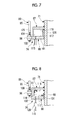
- a configuration is also acceptable in which the tubular portion 100 of the annular member 88 is eliminated and the annular members 87 and 88 are connected by two bellows 125 and 126 capable of expanding and contracting, as shown in Fig. 7 . That is, the bellows 125 on one side is made so as to have a larger diameter than the bellows 126 on the other side, and these bellows are coaxially disposed and respectively connected to the annular members 87 and 88.
- the fixing member 96 of the extension section 89 is connected to the basal plate portion 101 of the annular member 88.
- a pressure adjustment valve 128 (pressure adjustment means) for adjusting the pressure of the compressed air which is supplied to the pressure chamber 114 of the thrust absorption mechanism 74 may be provided in the supply pipe 115.
- the compressed air compressed in the medium-pressure compression mechanism 27 may be supplied to the pressure chambers 114 of, for example, the expansion joints 10(A) to 10(C). Further, pressure may be introduced from another device other than the compression mechanisms 27 and 28 into the pressure chambers 114 of the expansion joints 10 (A) to 10(E). In this case, a liquid pressure rather than a gas pressure may be introduced. That is, it is favorable if a fluid pressure is introduced into the pressure chamber 114.
- a bellows may be used as the connecting pipe 73 which connects the end pipes 71 and 72 so as to be capable of coming close to each other and separating from each other.
- the present invention can be widely applied to an expansion joint and a compression system in which relative displacement occurs at a position where both ends are connected.
Landscapes
- Engineering & Computer Science (AREA)
- General Engineering & Computer Science (AREA)
- Mechanical Engineering (AREA)
- Structures Of Non-Positive Displacement Pumps (AREA)
- Joints Allowing Movement (AREA)
- Quick-Acting Or Multi-Walled Pipe Joints (AREA)
Abstract
Description
- The present invention relates to an expansion joint and a compression system.
- As a joint which connects pipes to each other, there is an expansion joint which absorbs the thermal expansion of the pipe. As the expansion joint, there is an expansion joint having a structure which cancels a thrust due to an internal pressure which is generated in a direction separating pipes from each other or bringing pipes close to each other. For example, PTL 1 discloses an expansion joint using three bellows. The expansion joint specifically has the following structure. A guide flange section is mounted on each of both ends of one small-diameter bellows. A guide flange section is mounted on each of both ends of another small-diameter bellows. These small-diameter bellows are arranged in series and the facing guide flange sections among the guide flange sections mounted on these small-diameter bellows are connected by a large-diameter bellows. The guide flange section mounted on the side opposite to the large-diameter bellows of the small-diameter bellows on one side and the guide flange section mounted on the large-diameter bellows side of the small-diameter bellows on the other side are connected by a tie rod. The guide flange section mounted on the side opposite to the large-diameter bellows of the small-diameter bellows on the other side and the guide flange section mounted on the large-diameter bellows side of the small-diameter bellows on one side are connected by a tie rod.
- [PTL 1] Japanese Unexamined Patent Application Publication No.
2008-215607 - In the expansion joint having the above structure, in order to cancel a thrust, it is necessary to make the cross-sectional area in a direction orthogonal to an axis of the large-diameter bellows be twice that of the small-diameter bellows. For this reason, an increase in the size thereof is performed.
- The present invention has been made in view of the above circumstances and has an object to provide an expansion joint and a compression system in which a reduction in the size thereof is possible.
- A first aspect of an expansion joint according to the present invention is an expansion joint which connects pipes to each other and is capable of expanding and contracting, including: an end pipe on one side and an end pipe on the other side; a connecting pipe which connects the end pipe on one side and the end pipe on the other side so as to be capable of coming close to each other and separating from each other; and thrust-absorbing means having a pressure chamber which can expand and contract in a direction connecting the end pipe on one side and the end pipe on the other side and into which a fluid pressure different from a pressure in the pipes can be introduced, the pressure chamber having a pressure-receiving section on one side, which is fixed to the end pipe on one side and faces in a direction from the end pipe the other side to the end pipe on one side, and a pressure-receiving section on the other side, which is fixed to the end pipe on the other side and faces in a direction from the end pipe on one side to the end pipe on the other side.
- As a second aspect of the expansion joint according to the present invention, the pressure-receiving section on one side in the expansion joint according to the first aspect may be provided in an annular member on one side, which is fixed in an axial range of an outer peripheral surface of the end pipe on one side, and the pressure-receiving section on the other side in the expansion joint according to the first aspect may be provided in an annular member on the other side, which is fixed to an extension section extending toward the end pipe on one side from an outer peripheral surface of the end pipe on the other side and is disposed on a side opposite to the end pipe on the other side of the annular member on one side.
- As a third aspect of the expansion joint according to the present invention, the annular member on the other side in the expansion joint according to the second aspect may be provided with a tubular portion extending in a direction of the annular member on one side from an outer peripheral portion, and the expansion joint according to the second aspect may further include a seal member on one side, which seals a gap between an outer peripheral portion of the end pipe on one side and an inner peripheral portion of the annular member on the other side, and a seal member on the other side, which seals a gap between an inner peripheral portion of the tubular portion of the annular member on the other side and an outer peripheral portion of the annular member on one side.
- As a fourth aspect of the expansion joint according to the present invention, at least one of the seal member on one side and the seal member on the other side in the expansion joint according to the third aspect may be a lip seal.
- As a fifth aspect of the expansion joint according to the present invention, at least one of the seal member on one side and the seal member on the other side in the expansion joint according to the third aspect may be an 0-ring.
- As a sixth aspect of the expansion joint according to the present invention, the annular member on one side and the annular member on the other side in the expansion joint according to the second aspect may be connected by a bellows.
- A first aspect of a compression system according to the present invention is a compression system in which pipes are connected by the expansion joint described above.
- As a second aspect of the compression system according to the present invention, the compression system according to the first aspect may include compression mechanisms of plural stages, wherein a pipe for circulating a compressed gas discharged from the compression mechanism of an upstream stage and a pipe for circulating a compressed gas which is supplied to the compression mechanism of a downstream stage may be connected by the expansion joint.
- As a third aspect of the compression system according to the present invention, the thrust-absorbing means of the expansion joint in the compression system according to the second aspect may be provided with a supply pipe which supplies a compressed gas compressed in the compression mechanism further toward the downstream side than the expansion joint.
- As a fourth aspect of the compression system according to the present invention, the compression system according to any one of the first aspect to the third aspect may further include pressure adjustment means for adjusting a fluid pressure which is supplied to the thrust-absorbing means.
- According to the expansion joint related to the above aspect of the present invention, a reduction in size becomes possible.
-
-
Fig. 1 is a side view showing a compression system which includes an expansion joint according to an embodiment of the present invention. -
Fig. 2 is a plan view showing a compression system according to the embodiment. -
Fig. 3 is a side view showing the compression system according to the embodiment. -
Fig. 4 is a plan view showing a gas cooler of the compression system according to the embodiment. -
Fig. 5 is a partial cross-sectional view showing the expansion joint according to the embodiment. -
Fig. 6 is a partial cross-sectional view showing a modified example of the expansion joint according to the embodiment. -
Fig. 7 is a partial cross-sectional view showing another modified example of the expansion joint according to the embodiment. -
Fig. 8 is a partial cross-sectional view showing still another modified example of the expansion joint according to the embodiment. - Hereinafter, an expansion joint and a compression system according to an embodiment of the present invention will be described.
-
Fig. 1 shows anexpansion joint 10 according to this embodiment and acompression system 11 using theexpansion joint 10. A plurality ofexpansion joints 10 having the same structure are provided in thecompression system 11. In a case of distinguishing the plurality ofexpansion joints 10 from each other, theexpansion joints 10 are distinguished by adding (A), (B), (C), (D), or (E) to the respective signs. - The
compression system 11 is for producing a compressed gas by compressing a gas and specifically, is for producing compressed air by compressing air. In addition, thecompression system 11 may be a compression system which compresses a gas other than air. Thecompression system 11 has amotor 15 and acompressor 16, as shown inFig. 2 . Themotor 15 is driven by electric power, thereby rotating amotor shaft 17. - The
compressor 16 is a multi-axis and multi-stage geared compressor. Thecompressor 16 has adrive gear 21, a low-pressureside pinion shaft 22, and a high-pressureside pinion shaft 23. Thedrive gear 21 is connected to themotor shaft 17 and rotates by being driven by themotor shaft 17. The low-pressureside pinion shaft 22 and the high-pressureside pinion shaft 23 are engaged with thedrive gear 21 and are rotated by the driving of thedrive gear 21. - The
compressor 16 has low-pressure compression mechanisms pressure compression mechanism 27, a high-pressure compression mechanism 28, a low-pressure gas cooler 29, and a medium-pressure gas cooler 30. That is, thecompressor 16 has compression mechanisms of plural stages (specifically, three stages): the low-pressure compression mechanisms pressure compression mechanism 27, and the high-pressure compression mechanism 28. - The low-
pressure compression mechanism 25 on one side has an impeller (not shown) connected to one end of the low-pressureside pinion shaft 22, and acasing 35 which accommodates the impeller. The low-pressure compression mechanism 25 has anair intake duct 36 as a pipe mounted on one side of thecasing 35, and anexhaust air duct 37 as a pipe mounted on the other side of thecasing 35, as shown inFig. 1 . The low-pressure compression mechanism 25 draws in outside air from theair intake duct 36 by the rotation of the impeller (not shown), compresses the outside air to a predetermined compression ratio, and then discharges the compressed air from theexhaust air duct 37. - As shown in
Fig. 2 , the low-pressure compression mechanism 26 on the other side has an impeller (not shown) connected to the other end of the low-pressureside pinion shaft 22, and acasing 40 which accommodates the impeller. The low-pressure compression mechanism 26 has anair intake duct 41 as a pipe mounted on one side of thecasing 40, and anexhaust air duct 42 as a pipe mounted on the other side of thecasing 40, as shown inFig. 3 . The low-pressure compression mechanism 26 draws in outside air from theair intake duct 41 by the rotation of the impeller (not shown), compresses the outside air to a predetermined compression ratio, and then discharges the compressed air from theexhaust air duct 42. - The low-
pressure gas cooler 29 hasintroduction ports Fig. 4 . As shown inFig. 1 , theintroduction port 45 on one side is connected to theexhaust air duct 37 of the low-pressure compression mechanism 25 through the expansion joint 10(A). The compressed air discharged from the low-pressure compression mechanism 25 is introduced into the low-pressure gas cooler 29 through theintroduction port 45. As shown inFig. 3 , theintroduction port 46 on the other side is connected to theexhaust air duct 42 of the low-pressure compression mechanism 26 through the expansion joint 10(B). The compressed air discharged from the low-pressure compression mechanism 26 is introduced into the low-pressure gas cooler 29 through theintroduction port 46. The low-pressure gas cooler 29 cools the compressed air introduced from theintroduction ports discharge port 47 as a pipe for discharging the stored compressed air, as shown inFig. 1 . - As shown in
Fig. 2 , the medium-pressure compression mechanism 27 has an impeller (not shown) connected to one end of the high-pressureside pinion shaft 23, and acasing 50 which accommodates the impeller. The medium-pressure compression mechanism 27 has anair intake duct 51 as a pipe mounted on one side of thecasing 50, and anexhaust air duct 52 as a pipe mounted on the other side of thecasing 50, as shown inFig. 1 . The medium-pressure compression mechanism 27 is connected, at theair intake duct 51, to thedischarge port 47 of the low-pressure gas cooler 29 through the expansion joint 10(C), and draws in the compressed air of the low-pressure gas cooler 29 from theair intake duct 51 by the rotation of the impeller (not shown), further compresses the compressed air, and then discharges the compressed air from theexhaust air duct 52. - As described above, the expansion joint 10(A) shown in
Fig. 1 connects theexhaust air duct 37 for circulating the compressed air discharged from the low-pressure compression mechanism 25 of an upstream stage, and theintroduction port 45 for circulating the compressed air which is supplied to the medium-pressure compression mechanism 27 of a downstream stage through the low-pressure gas cooler 29. The expansion joint 10(B) shown inFig. 3 connects theexhaust air duct 42 for circulating the compressed air discharged from the low-pressure compression mechanism 26 of the upstream stage, and theintroduction port 46 for circulating the compressed air which is supplied to the medium-pressure compression mechanism 27 of the downstream stage through the low-pressure gas cooler 29. The expansion joint 10(C) shown inFig. 1 connects thedischarge port 47 for circulating the compressed air discharged from the low-pressure compression mechanisms pressure gas cooler 29, and theair intake duct 51 for circulating the compressed air which is supplied to the medium-pressure compression mechanism 27 of the downstream stage. - The medium-pressure gas cooler 30 has an
introduction port 55 as a pipe, as shown inFig. 4 . As shown inFig. 1 , theintroduction port 55 is connected to theexhaust air duct 52 of the medium-pressure compression mechanism 27 through the expansion joint 10(D). The compressed air discharged from the medium-pressure compression mechanism 27 is introduced into the medium-pressure gas cooler 30 through theintroduction port 55. The medium-pressure gas cooler 30 cools the compressed air introduced from theintroduction port 55 while storing the compressed air. The medium-pressure gas cooler 30 has adischarge port 56 as a pipe for discharging the stored compressed air, as shown inFig. 3 . - As shown in
Fig. 2 , the high-pressure compression mechanism 28 has an impeller (not shown) connected to the other end of the high-pressureside pinion shaft 23, and acasing 60 which accommodates the impeller. The high-pressure compression mechanism 28 has anair intake duct 61 as a pipe mounted on one side of thecasing 60, and anexhaust air duct 62 as a pipe mounted on the other side of thecasing 60, as shown inFig. 3 . The high-pressure compression mechanism 28 is connected, at theair intake duct 61, to thedischarge port 56 of the medium-pressure gas cooler 30 through the expansion joint 10(E), and draws in the compressed air of the medium-pressure gas cooler 30 from theair intake duct 61 by the rotation of the impeller (not shown), further compresses the compressed air, and then discharges the compressed air from theexhaust air duct 62. Although illustration is omitted, theexhaust air duct 62 is connected to a pipe leading to a supply destination of compressed air. - As described above, the expansion joint 10(D) shown in
Fig. 1 connects theexhaust air duct 52 for circulating the compressed air discharged from the medium-pressure compression mechanism 27 of the upstream stage, and theintroduction port 55 for circulating the compressed air which is supplied to the high-pressure compression mechanism 28 of the downstream stage through the medium-pressure gas cooler 30. The expansion joint 10(E) shown inFig. 3 connects thedischarge port 56 for circulating the compressed air discharged from the medium-pressure compression mechanism 27 of the upstream stage through the medium-pressure gas cooler 30, and theair intake duct 61 for circulating the compressed air which is supplied to the high-pressure compression mechanism 28 of the downstream stage. - The inside of each of the
exhaust air ducts pressure compression mechanisms pressure gas cooler 29, the expansion joint 10(C), and theair intake duct 51 of the medium-pressure compression mechanism 27 has a pressure which is higher than atmospheric pressure. The inside of each of theexhaust air duct 52 of the medium-pressure compression mechanism 27, the expansion joint 10(D), the medium-pressure gas cooler 30, the expansion joint 10(E), and theair intake duct 61 of the high-pressure compression mechanism 28 is in a higher pressure state than theexhaust air ducts pressure gas cooler 29, and theair intake duct 51. The inside of theexhaust air duct 62 of the high-pressure compression mechanism 28 is in a higher pressure state than theexhaust air duct 52, the expansion joint 10(D), the medium-pressure gas cooler 30, the expansion joint 10(E), and theair intake duct 61. - The expansion joints 10(A) to 10(E) described above have the same structure, although there is a difference in the size of each section according to application conditions. In addition, the application conditions refer to the size and position of a pipe to be connected, the flow rate and pressure of compressed air passing through the inside thereof, or the like. Specifically, the expansion joint 10(A) connecting the
exhaust air duct 37 of the low-pressure compression mechanism 25 and theintroduction port 45 of the low-pressure gas cooler 29, and the expansion joint 10(B) connecting theexhaust air duct 42 of the low-pressure compression mechanism 26 and theintroduction port 46 of the low-pressure gas cooler 29 have common components having the same size. The expansion joint 10(C) connecting thedischarge port 47 of the low-pressure gas cooler 29 and theair intake duct 51 of the medium-pressure compression mechanism 27 has a larger size than the expansion joints 10(A) and 10(B) in order to circulate the compressed air from the two low-pressure compression mechanism exhaust air duct 52 of the medium-pressure compression mechanism 27 and theintroduction port 55 of the medium-pressure gas cooler 30 has a smaller size than the expansion joint 10(C). The expansion joint 10 (E) connecting thedischarge port 56 of the medium-pressure gas cooler 30 and theair intake duct 61 of the high-pressure compression mechanism 28 has a common component having the same size as the expansion joint 10(D). - As shown in
Fig. 5 , theexpansion joint 10 has twoend pipes pipe 73, and a thrust absorption mechanism 74 (thrust-absorbing means). Theend pipe 71 on one side which is one of theend pipes end pipe 72 on the other side which is one of theend pipes end pipe 71 and theend pipe 72 are disposed in series. - The connecting
pipe 73 connects theend pipe 71 and theend pipe 72 so as to be capable of coming close to each other and separating from each other while coaxially disposing theend pipe 71 and theend pipe 72. The connectingpipe 73 has aseal ring 77, a retainingring 78, and a pair of regulating rings 79 and 80. Theseal ring 77 has a tubular shape and is made of rubber. Theseal ring 77 comes into contact with an end portion on theend pipe 72 side of the outer peripheral surface of theend pipe 71 at an inner peripheral surface on one side in an axial direction. Further, theseal ring 77 comes into contact with an end portion on theend pipe 71 side of the outer peripheral surface of theend pipe 72 at an inner peripheral surface on the other side in the axial direction. - The regulating
ring 79 is fixed further toward the side opposite to theend pipe 72 than theseal ring 77 of the outer peripheral surface of theend pipe 71. The regulatingring 80 is fixed further toward the side opposite to theend pipe 71 than theseal ring 77 of the outer peripheral surface of theend pipe 72. In the retainingring 78, a centralannular groove 82 and a pair ofannular grooves annular groove 82 is formed at the middle position in the axial direction of the retainingring 78. The pair ofannular grooves annular groove 82. The width in the axial direction of the centralannular groove 82 is made to be wider than the pair ofannular grooves - The
seal ring 77 is fitted into the centralannular groove 82. The retainingring 78 presses theseal ring 77 against the outer peripheral surfaces of theend pipe 71 and theend pipe 72. Theannular groove 83 is longer than the regulatingring 79 in the axial direction and is disposed so as to cover the regulatingring 79. Accordingly, the retainingring 78 can relatively move with respect to theend pipe 71 in the axial direction by an amount corresponding to the gap between theannular groove 83 and the regulatingring 79. Theannular groove 84 is longer than the regulatingring 80 in the axial direction and is disposed so as to cover the regulatingring 80. Accordingly, the retainingring 78 can relatively move with respect to theend pipe 72 in the axial direction by an amount corresponding to the gap between theannular groove 84 and the regulatingring 80. Accordingly, theend pipes ring 78. Theseal ring 77 always seals the gap between theend pipes end pipes - The
thrust absorption mechanism 74 has twoannular members extension section 89, and twoseal members annular member 87 on one side which is one of the twoannular members end pipe 71 at the inner peripheral surface thereof. Accordingly, theannular member 87 is fixed in an axial range of the outer peripheral surface of theend pipe 71. Theannular member 87 extends so as to be orthogonal to an axis of theend pipe 71. Theannular member 87 and theend pipe 71 are fixed to each other without a clearance therebetween by welding. - The
extension section 89 has a fixingplate 93, a fixingmember 94, atie rod 95, and a fixingmember 96. The fixingplate 93 has a perforated disk shape and is directly fixed to the outer peripheral surface of theend pipe 72 on the inner peripheral surface thereof. Accordingly, the fixingplate 93 is fixed in an axial range of theend pipe 72. The fixingplate 93 extends so as to be orthogonal to an axis of theend pipe 72. The fixingmember 94 is fixed to an outer peripheral end portion of the fixingplate 93. Thetie rod 95 is fixed to the fixingmember 94 at one end portion and extends parallel to theend pipes end pipe 71 from the fixingmember 94. Accordingly, theextension section 89 extends toward theend pipe 71 from the outer peripheral surface of theend pipe 72. Thetie rod 95 extends to the side opposite to theend pipe 72 of theannular member 87 beyond the outer periphery side of theannular member 87. The fixingmember 96 is fixed to the other end portion of thetie rod 95. - The
annular member 88 on the other side which is one of the twoannular members tubular portion 100 and abasal plate portion 101. Thetubular portion 100 has a cylindrical shape and the fixingmember 96 of theextension section 89 described above is fixed to the outer peripheral surface thereof. Accordingly, theannular member 88 is fixed to theextension section 89. Thetubular portion 100 is disposed further toward the outside in a radial direction than the outer peripheral surface of theannular member 87. Thebasal plate portion 101 extends radially inward from the side opposite to theend pipe 72 in the axial direction of thetubular portion 100. Accordingly, in theannular member 88, thetubular portion 100 extending in the direction of theannular member 87 from the outer periphery side of thebasal plate portion 101 is provided. Thebasal plate portion 101 has a perforated disk shape and theend pipe 71 is inserted into the inside thereof. Apassage hole 102 penetrating in the axial direction is formed in thebasal plate portion 101. Thebasal plate portion 101 of theannular member 88 is disposed on the side opposite to theend pipe 72 of theannular member 87. Thebasal plate portion 101 is disposed in an axial range of theend pipe 71. Thebasal plate portion 101 extends so as to be orthogonal to the axis of theend pipe 71. - The
seal member 90 on one side which is one of the twoseal members lip portion 104 and alip portion 105. Thelip portion 104 has a perforated disk shape, and thelip portion 105 has a cylindrical shape extending in the axial direction from an inner peripheral edge portion of thelip portion 104. Accordingly, theseal member 90 has an L-shaped cross-section. - In the
basal plate portion 101 of theannular member 88, a lockingmember 106 is fixed to the inner periphery side thereof on theannular member 87 side in the axial direction. Theseal member 90 is locked to the lockingmember 106 at thelip portion 104. Theseal member 90 is in contact with an end face on theannular member 87 side of thebasal plate portion 101 of theannular member 88 at thelip portion 104. Further, theseal member 90 comes into sliding contact with the outer peripheral surface of theend pipe 71 at thelip portion 105. In this way, theseal member 90 seals the gap between an outer peripheral portion of theend pipe 71 and an inner peripheral portion of thebasal plate portion 101 of theannular member 88. - The
seal member 91 on the other side which is one of the twoseal members lip portion 108 and alip portion 109. Thelip portion 108 has a perforated disk shape, and thelip portion 109 has a cylindrical shape extending in the axial direction from an outer peripheral edge portion of thelip portion 108. Accordingly, theseal member 91 has an L-shaped cross-section. - In the
annular member 87, a lockingmember 110 is fixed to the outer periphery side thereof on theannular member 88 side in the axial direction. Theseal member 91 is locked to the lockingmember 110 at thelip portion 108. That is, theseal member 91 is in contact with an end face on theannular member 88 side of theannular member 87 at thelip portion 108. Further, theseal member 91 comes into sliding contact with the inner peripheral surface of thetubular portion 100 of theannular member 88 at thelip portion 109. In this way, theseal member 91 seals the gap between an inner peripheral portion of thetubular portion 100 of theannular member 88 and an outer peripheral portion of theannular member 87. - A portion surrounded by the
end pipe 71, theannular members seal members pressure chamber 114. A fluid pressure on the outside can be introduced into thepressure chamber 114 through thepassage hole 102 of theannular member 88 and asupply pipe 115 communicating with thepassage hole 102. - As described above, the
annular member 87 is fixed to theend pipe 71 and moves integrally with theend pipe 71. Theannular member 88 is fixed to theend pipe 72 through theextension section 89 and moves integrally with theend pipe 72. If theend pipes annular members end pipes annular members pressure chamber 114 expands in the axial direction if theend pipes end pipes pressure chamber 114 can expand and contract in a direction connecting theend pipe 71 and theend pipe 72. - The
pressure chamber 114 has two pressure-receivingsections section 116 on one side which is one of the pressure-receivingsections annular member 87 fixed to theend pipe 71. Accordingly, the pressure-receivingsection 116 is fixed to theend pipe 71. The pressure-receivingsection 116 faces in the direction from theend pipe 72 to the end pipe 71 (a downward direction inFig. 5 ). - The pressure-receiving
section 117 on the other side which is one of the pressure-receivingsections basal plate portion 101 of theannular member 88 fixed to theend pipe 72. Accordingly, the pressure-receivingsection 117 is fixed to theend pipe 72. The pressure-receivingsection 117 faces in the direction from theend pipe 71 to the end pipe 72 (an upward direction inFig. 5 ). - If a pressure which is higher than atmospheric pressure is introduced into the
pressure chamber 114 through thesupply pipe 115, the pressure-receivingsections pressure chamber 114, the pressure-receivingsections end pipe 71 and an internal pressure Pi and the product of an area Ac of the pressure-receivingsection 116 and an internal pressure Pc of thepressure chamber 114 are made to equal to each other. In this way, a thrust which is generated in theend pipe 71 is cancelled. Similarly, the product of the cross-sectional area Ai of theend pipe 72 and the internal pressure Pi and the product of the area Ac of the pressure-receivingsection 117 and the internal pressure Pc of thepressure chamber 114 are made to equal to each other. In this way, a thrust which is generated in theend pipe 72 is cancelled. - Specifically, in the expansion joints 10(A) to 10(E), a pressure from the
exhaust air duct 62 of the high-pressure compression mechanism 28 shown inFig. 3 is introduced into thepressure chambers 114 of the respectivethrust absorption mechanisms 74 through thesupply pipe 115. That is, thesupply pipe 115 supplies the compressed air compressed in the high-pressure compression mechanism 28 further toward the downstream side than the expansion joints 10(A) to 10(E), to thethrust absorption mechanisms 74 of the expansion joints 10(A) to 10(E). - Accordingly, a gas pressure which is different from and is a pressure higher than the pressure in the
exhaust air duct 37 and theintroduction port 45 which are connected by the expansion joint 10(A) is introduced into thepressure chamber 114 of thethrust absorption mechanism 74 of the expansion joint 10(A). Here, in theend pipes exhaust air duct 37 and theintroduction port 45 due to the inner gas pressure. In contrast, the pressure-receivingsection 116 of thepressure chamber 114 receives a gas pressure in a direction bringing theend pipe 71 close to theend pipe 72. Further, the pressure-receivingsection 117 receives a gas pressure in a direction bringing theend pipe 72 close to theend pipe 71. That is, in thethrust absorption mechanism 74, a thrust in a direction cancelling the thrust in theexhaust air duct 37 and theintroduction port 45 is generated. - At this time, the pressure-receiving areas of the pressure-receiving
sections exhaust air duct 37 and theintroduction port 45 are set such that the thrust which is generated in theexhaust air duct 37 and theintroduction port 45 due to the inner gas pressure (that is, the thrust which is generated in theend pipes 71 and 72) balances with the thrust which is generated in theend pipes thrust absorption mechanism 74. Into thepressure chamber 114, a gas pressure higher than the pressure in theexhaust air duct 37 and theintroduction port 45 is introduced. For this reason, it is possible to make the pressure-receiving areas of the pressure-receivingsections exhaust air duct 37 and theintroduction port 45. Accordingly, the expansion joint 10 (A) which includes thethrust absorption mechanism 74 can be reduced in size in the radial direction. - Also into the
pressure chamber 114 of thethrust absorption mechanism 74 of the expansion joint 10(B), a gas pressure which is different from and is a pressure higher than the pressure in theexhaust air duct 42 and theintroduction port 46 which are connected by the expansion joint 10(B) is introduced. Also into thepressure chamber 114 of thethrust absorption mechanism 74 of the expansion joint 10(C), a gas pressure which is different from and is a pressure higher than the pressure in thedischarge port 47 and theair intake duct 51 which are connected by the expansion joint 10(C) is introduced. Also into thepressure chamber 114 of thethrust absorption mechanism 74 of the expansion joint 10(D), a gas pressure which is different from and is a pressure higher than the pressure in theexhaust air duct 52 and theintroduction port 55 which are connected by the expansion joint 10(D) is introduced. Also into thepressure chamber 114 of thethrust absorption mechanism 74 of the expansion joint 10(E), a gas pressure which is different from and is a pressure higher than the pressure in thedischarge port 56 and theair intake duct 61 which are connected by the expansion joint 10(E) is introduced. Also with respect to the expansion joints 10(B) to 10(E), the pressure-receiving areas of the pressure-receivingsections end pipes - In the
expansion joint 10 of the above-described embodiment, thepressure chamber 114 of thethrust absorption mechanism 74 can expand and contract in a direction connecting theend pipes pressure chamber 114 has the pressure-receivingsection 116 which is fixed to theend pipe 71 and faces in the direction from theend pipe 72 to theend pipe 71. Thepressure chamber 114 has the pressure-receivingsection 117 on the other side, which is fixed to theend pipe 72 and faces in the direction from theend pipe 71 to theend pipe 72. With these configurations, in a case where the pressure in the pipes which are connected by theexpansion joint 10 is positive pressure, by introducing a pressure higher than the pressure into thepressure chamber 114, it is possible to cancel a thrust which is generated in the pipes, even if the pressure-receivingsections expansion joint 10 which includes thethrust absorption mechanism 74 can be reduced in size. - Further, the pressure-receiving
section 116 is provided in theannular member 87 which is fixed in an axial range of the outer peripheral surface of theend pipe 71. The pressure-receivingsection 117 is provided in theannular member 88 which is fixed to theextension section 89 extending toward theend pipe 71 from the outer peripheral surface of theend pipe 72 and is disposed on the side opposite to theend pipe 72 of theannular member 87. With these configurations, theexpansion joint 10 which includes thethrust absorption mechanism 74 can be reliably reduced in size. - Further, in the
annular member 88, thetubular portion 100 extending in the direction of theannular member 87 from the outer peripheral portion is provided. The gap between the outer peripheral portion of theend pipe 71 and the inner peripheral portion of theannular member 88 is sealed by theseal member 90. The gap between the inner peripheral portion of thetubular portion 100 of theannular member 88 and the outer peripheral portion of theannular member 87 is sealed by theseal member 91. With these configurations, it is possible to make thepressure chamber 114 be able to expand and contract with a simple structure. - Further, the
seal member 90 is made to be a lip seal. Accordingly, theseal member 90 is brought into close contact with theend pipe 71 and theannular member 88 by the pressure in thepressure chamber 114. Therefore, it is possible to obtain excellent sealability. Theseal member 91 is also made to be a lip seal. Accordingly, theseal member 91 is brought into close contact with theannular members pressure chamber 114. Therefore, it is possible to obtain excellent sealability. - In the
compression system 11 of the above-described embodiment, theexhaust air duct 37 as a pipe and theintroduction port 45 as a pipe are connected by the expansion joint 10(A). Further, theexhaust air duct 42 as a pipe and theintroduction port 46 as a pipe are connected by the expansion joint 10(B). Further, thedischarge port 47 as a pipe and theair intake duct 51 as a pipe are connected by the expansion joint 10(C). Further, theexhaust air duct 52 as a pipe and theintroduction port 55 as a pipe are connected by the expansion joint 10(D). Further, thedischarge port 56 as a pipe and theair intake duct 61 as a pipe are connected by the expansion joint 10(E). As described above, the expansion joints 10(A) to 10(E) can be reduced in size, and therefore, it is possible to attain a compact layout of each pipe, and thus it becomes possible to attain a reduction in the size of the entirety of thecompression system 11. - The
compression system 11 has the low-pressure compression mechanism pressure compression mechanism 27, and the high-pressure compression mechanism 28 of plural stages. Then, theexhaust air duct 37 for circulating the compressed air discharged from the low-pressure compression mechanism 25 of the upstream stage and theintroduction port 45 for circulating the compressed air which is supplied to the medium-pressure compression mechanism 27 of the downstream stage are connected by the expansion joint 10(A). Along with this, the compressed air compressed in the high-pressure compression mechanism 28 further toward the downstream side than the expansion joint 10(A) is supplied to thethrust absorption mechanism 74 of the expansion joint 10(A) by thesupply pipe 115. As a result, the expansion joint 10(A) which includes thethrust absorption mechanism 74 can be reduced in size. Therefore, in particular, it is possible to attain a compact layout of the pipe connecting the low-pressure compression mechanism 25 and the medium-pressure compression mechanism 27. - Similarly, the
exhaust air duct 42 for circulating the compressed air discharged from the low-pressure compression mechanism 26 of the upstream stage and theintroduction port 46 for circulating the compressed air which is supplied to the medium-pressure compression mechanism 27 of the downstream stage are connected by the expansion joint 10(B). Along with this, the compressed air compressed in the high-pressure compression mechanism 28 further toward the downstream side than the expansion joint 10(B) is supplied to thethrust absorption mechanism 74 of the expansion joint 10 (B) by thesupply pipe 115. As a result, the expansion joint 10(B) which includes thethrust absorption mechanism 74 can be reduced in size. Therefore, in particular, it is possible to attain a compact layout of the pipe connecting the low-pressure compression mechanism 26 and the medium-pressure compression mechanism 27. - Similarly, the
discharge port 47 for circulating the compressed air discharged from the low-pressure compression mechanisms air intake duct 51 for circulating the compressed air which is supplied to the medium-pressure compression mechanism 27 of the downstream stage are connected by the expansion joint 10(C). Along with this, the compressed air compressed in the high-pressure compression mechanism 28 further toward the downstream side than the expansion joint 10(C) is supplied to thethrust absorption mechanism 74 of the expansion joint 10(C) by thesupply pipe 115. As a result, the expansion joint 10(C) which includes thethrust absorption mechanism 74 can be reduced in size. Therefore, in particular, it is possible to attain a compact layout of the pipe connecting the low-pressure compression mechanisms pressure compression mechanism 27. - Similarly, the
exhaust air duct 52 for circulating the compressed air discharged from the medium-pressure compression mechanism 27 of the upstream stage and theintroduction port 55 for circulating the compressed air which is supplied to the high-pressure compression mechanism 28 of the downstream stage are connected by the expansion joint 10(D). Along with this, the compressed air compressed in the high-pressure compression mechanism 28 further toward the downstream side than the expansion joint 10(D) is supplied to thethrust absorption mechanism 74 of the expansion joint 10 (D) by thesupply pipe 115. As a result, the expansion joint 10(D) which includes thethrust absorption mechanism 74 can be reduced in size. Therefore, in particular, it is possible to attain a compact layout of the pipe connecting the medium-pressure compression mechanism 27 and the high-pressure compression mechanism 28. - Similarly, the
discharge port 56 for circulating the compressed air discharged from the medium-pressure compression mechanism 27 of the upstream stage and theair intake duct 61 for circulating the compressed air which is supplied to the high-pressure compression mechanism 28 of the downstream stage are connected by the expansion joint 10(E). Along with this, the compressed air compressed in the high-pressure compression mechanism 28 further toward the downstream side than the expansion joint 10(E) is supplied to thethrust absorption mechanism 74 of the expansion joint 10(E) by thesupply pipe 115. As a result, the expansion joint 10(E) which includes thethrust absorption mechanism 74 can be reduced in size. Therefore, in particular, it is possible to attain a compact layout of the pipe connecting the medium-pressure compression mechanism 27 and the high-pressure compression mechanism 28. - In the
compression system 11, a fluid pressure for being introduced into thethrust absorption mechanisms 74 of the expansion joint 10(A) to the expansion joint 10(E) can be produced in thecompression system 11. Therefore, separate fluid pressure supply means from thecompression system 11 is not required, and thus cost can be reduced. - In addition, the present invention is not limited to the above-described embodiment and includes forms in which various changes are applied to the above-described embodiment within a scope which does not depart from the gist of the present invention. That is, specific shapes, configurations, or the like mentioned in the embodiment are merely examples, and changes can be appropriately made thereto.
- For example, in the
thrust absorption mechanism 74, instead of theseal members seal members Fig. 6 . In this case, aconcave portion 123 recessed radially outward is formed in the inner peripheral surface of thebasal plate portion 101 of theannular member 88. Then, theseal member 121 is disposed in theconcave portion 123 so as to come into contact with the outer peripheral surface of theend pipe 71. Further, aconcave portion 124 recessed radially inward is formed in the outer peripheral surface of theannular member 87. Then, theseal member 122 is disposed in theconcave portion 124 so as to come into contact with the inner peripheral surface of thetubular portion 100 of theannular member 88. In this way, it is possible to eliminate the lockingmembers seal member 90 and theseal member 122 is also acceptable, and a combination of theseal member 91 and theseal member 121 is also acceptable. - Further, for example, in the
thrust absorption mechanism 74, a configuration is also acceptable in which thetubular portion 100 of theannular member 88 is eliminated and theannular members bellows Fig. 7 . That is, thebellows 125 on one side is made so as to have a larger diameter than thebellows 126 on the other side, and these bellows are coaxially disposed and respectively connected to theannular members member 96 of theextension section 89 is connected to thebasal plate portion 101 of theannular member 88. In this structure, a space between thebellows 125 having a larger diameter and thebellows 126 having a smaller diameter becomes thepressure chamber 114. In this way, it is possible to eliminate theseal members - Further, as shown in
Fig. 8 , a pressure adjustment valve 128 (pressure adjustment means) for adjusting the pressure of the compressed air which is supplied to thepressure chamber 114 of thethrust absorption mechanism 74 may be provided in thesupply pipe 115. By adjusting the pressure of the compressed air which is supplied to thepressure chamber 114 by thepressure adjustment valve 128, it becomes possible to effectively cancel a thrust which is generated in theend pipes - It is favorable if a fluid pressure which is higher than the internal pressure of the pipes which are connected by each of the expansion joints 10(A) to 10(E) is introduced into the
pressure chamber 114 of thethrust absorption mechanism 74. Accordingly, the compressed air compressed in the medium-pressure compression mechanism 27 may be supplied to thepressure chambers 114 of, for example, the expansion joints 10(A) to 10(C). Further, pressure may be introduced from another device other than thecompression mechanisms pressure chambers 114 of the expansion joints 10 (A) to 10(E). In this case, a liquid pressure rather than a gas pressure may be introduced. That is, it is favorable if a fluid pressure is introduced into thepressure chamber 114. - Further, a bellows may be used as the connecting
pipe 73 which connects theend pipes - The present invention can be widely applied to an expansion joint and a compression system in which relative displacement occurs at a position where both ends are connected.
-
- 10(A) to 10(E): expansion joint
- 11: compression system
- 25, 26: low-pressure compression mechanism
- 27: medium-pressure compression mechanism
- 28: high-pressure compression mechanism
- 37, 42, 52, 62: exhaust air duct (pipe)
- 41, 51, 61: air intake duct (pipe)
- 45, 46, 55: introduction port (pipe)
- 47, 56: discharge port (pipe)
- 71, 72: end pipe
- 73: connecting pipe
- 74: thrust absorption mechanism (thrust-absorbing means)
- 87, 88: annular member
- 89: extension section
- 90, 91, 121, 122: seal member
- 100: tubular portion
- 114: pressure chamber
- 115: supply pipe
- 116, 117: pressure-receiving section
- 125, 126: bellows
- 128: pressure adjustment valve (pressure adjustment means)
Claims (10)
- An expansion joint which connects pipes to each other and is capable of expanding and contracting, comprising:an end pipe on one side and an end pipe on the other side;a connecting pipe which connects the end pipe on one side and the end pipe on the other side so as to be capable of coming close to each other and separating from each other; andthrust-absorbing means having a pressure chamber which can expand and contract in a direction connecting the end pipe on one side and the end pipe on the other side and into which a fluid pressure different from a pressure in the pipes can be introduced, the pressure chamber having a pressure-receiving section on one side, which is fixed to the end pipe on one side and faces in a direction from the end pipe the other side to the end pipe on one side, and a pressure-receiving section on the other side, which is fixed to the end pipe on the other side and faces in a direction from the end pipe on one side to the end pipe on the other side.
- The expansion joint according to Claim 1, wherein the pressure-receiving section on one side is provided in an annular member on one side, which is fixed in an axial range of an outer peripheral surface of the end pipe on one side, and
the pressure-receiving section on the other side is provided in an annular member on the other side, which is fixed to an extension section extending toward the end pipe on one side from an outer peripheral surface of the end pipe on the other side and is disposed on a side opposite to the end pipe on the other side of the annular member on one side. - The expansion joint according to Claim 2, wherein the annular member on the other side is provided with a tubular portion extending in a direction of the annular member on one side from an outer peripheral portion, and
the expansion joint further includes
a seal member on one side, which seals a gap between an outer peripheral portion of the end pipe on one side and an inner peripheral portion of the annular member on the other side, and
a seal member on the other side, which seals a gap between an inner peripheral portion of the tubular portion of the annular member on the other side and an outer peripheral portion of the annular member on one side. - The expansion joint according to Claim 3, wherein at least one of the seal member on one side and the seal member on the other side is a lip seal.
- The expansion joint according to Claim 3, wherein at least one of the seal member on one side and the seal member on the other side is an 0-ring.
- The expansion joint according to Claim 2, wherein the annular member on one side and the annular member on the other side are connected by a bellows.
- A compression system in which pipes are connected by the expansion joint according to any one of Claims 1 to 6.
- The compression system according to Claim 7, comprising:compression mechanisms of plural stages,wherein a pipe for circulating a compressed gas discharged from the compression mechanism of an upstream stage and a pipe for circulating a compressed gas which is supplied to the compression mechanism of a downstream stage are connected by the expansion joint.
- The compression system according to Claim 8, wherein the thrust-absorbing means of the expansion joint is provided with a supply pipe which supplies a compressed gas compressed in the compression mechanism further toward the downstream side than the expansion joint.
- The compression system according to any one of Claims 7 to 9, further comprising:pressure adjustment means for adjusting a fluid pressure which is supplied to the thrust-absorbing means.
Applications Claiming Priority (1)
| Application Number | Priority Date | Filing Date | Title |
|---|---|---|---|
| PCT/JP2013/054545 WO2014128924A1 (en) | 2013-02-22 | 2013-02-22 | Expansion joint and compression system |
Publications (3)
| Publication Number | Publication Date |
|---|---|
| EP2947363A1 true EP2947363A1 (en) | 2015-11-25 |
| EP2947363A4 EP2947363A4 (en) | 2015-12-23 |
| EP2947363B1 EP2947363B1 (en) | 2017-07-19 |
Family
ID=51390749
Family Applications (1)
| Application Number | Title | Priority Date | Filing Date |
|---|---|---|---|
| EP13875509.5A Not-in-force EP2947363B1 (en) | 2013-02-22 | 2013-02-22 | Expansion joint and compression system |
Country Status (5)
| Country | Link |
|---|---|
| US (1) | US10240700B2 (en) |
| EP (1) | EP2947363B1 (en) |
| JP (1) | JP5922837B2 (en) |
| CN (1) | CN104995444B (en) |
| WO (1) | WO2014128924A1 (en) |
Families Citing this family (4)
| Publication number | Priority date | Publication date | Assignee | Title |
|---|---|---|---|---|
| EP3344929B1 (en) | 2015-07-13 | 2024-01-10 | Fulton Group N.A., Inc. | High efficiency fluid heating system exhaust manifold |
| CN108431540A (en) * | 2015-07-24 | 2018-08-21 | 杭州富尔顿热能设备有限公司 | Flexible expansion heat transfer system including compressive seal expansion pipe |
| WO2019136923A1 (en) * | 2018-01-15 | 2019-07-18 | 江苏大学 | Magnetic fluid sealing pipeline connection compensation apparatus |
| CN112078754A (en) * | 2020-08-13 | 2020-12-15 | 沪东中华造船(集团)有限公司 | Installation method of unconstrained expansion joint |
Family Cites Families (16)
| Publication number | Priority date | Publication date | Assignee | Title |
|---|---|---|---|---|
| US1513315A (en) * | 1920-10-20 | 1924-10-28 | Cook Charles Lee | Self-balancing pipe expansion joint |
| US2308757A (en) * | 1941-08-16 | 1943-01-19 | Universal Oil Prod Co | Expansion joint |
| US2348833A (en) | 1942-12-22 | 1944-05-16 | Westinghouse Electric & Mfg Co | Expansion joint construction |
| FR1358270A (en) * | 1963-06-05 | 1964-04-10 | Plessey Co Ltd | Bellows-type expansion joint providing pressure compensation |
| FR2174343A5 (en) * | 1972-02-29 | 1973-10-12 | Delattre Levivier | |
| US3889985A (en) * | 1973-01-29 | 1975-06-17 | Swiss Corp Limited | Pressure compensated expansion joint |
| US4687639A (en) * | 1982-04-07 | 1987-08-18 | Phillips Petroleum Company | Apparatus for accommodating temperature and pressure variations in tubular conduits |
| US4603887A (en) * | 1984-10-01 | 1986-08-05 | Halliburton Company | Rigid adjustable length assembly |
| US4720124A (en) * | 1985-08-02 | 1988-01-19 | Cameron Iron Works, Inc. | Telescoping joint |
| JPH11230446A (en) * | 1998-02-12 | 1999-08-27 | Nippon Victaulic Kk | Slip-out prevention device for slide type joint mechanism |
| JP2007332826A (en) | 2006-06-13 | 2007-12-27 | Kobe Steel Ltd | Centrifugal compressor |
| JP2008215607A (en) * | 2007-02-09 | 2008-09-18 | Koji Uno | Bellows non-thrust expansion pipe joint |
| BRPI0903515A2 (en) * | 2009-09-16 | 2011-05-24 | Whirlpool Sa | thermal insulation, suitable for insulation of a gas discharge pipe from a refrigeration compressor and process of mounting insulation on the gas discharge pipe |
| HRP20100267B1 (en) * | 2010-05-13 | 2015-03-27 | Numikon D.O.O. | In line pressure balancing device for compensation thermal dilatation with jointing elements located inside the device |
| CN103635733B (en) * | 2011-07-06 | 2015-05-20 | 日本维克托利克株式会社 | Flexible expansion joint |
| CN202252575U (en) * | 2011-09-23 | 2012-05-30 | 开封黄河空分集团有限公司 | pipeline expansion joint |
-
2013
- 2013-02-22 US US14/768,627 patent/US10240700B2/en active Active
- 2013-02-22 WO PCT/JP2013/054545 patent/WO2014128924A1/en not_active Ceased
- 2013-02-22 JP JP2015501190A patent/JP5922837B2/en not_active Expired - Fee Related
- 2013-02-22 CN CN201380073260.5A patent/CN104995444B/en not_active Expired - Fee Related
- 2013-02-22 EP EP13875509.5A patent/EP2947363B1/en not_active Not-in-force
Also Published As
| Publication number | Publication date |
|---|---|
| JPWO2014128924A1 (en) | 2017-02-02 |
| WO2014128924A1 (en) | 2014-08-28 |
| EP2947363A4 (en) | 2015-12-23 |
| EP2947363B1 (en) | 2017-07-19 |
| US10240700B2 (en) | 2019-03-26 |
| CN104995444B (en) | 2017-03-08 |
| US20160003389A1 (en) | 2016-01-07 |
| JP5922837B2 (en) | 2016-05-24 |
| CN104995444A (en) | 2015-10-21 |
Similar Documents
| Publication | Publication Date | Title |
|---|---|---|
| US8210804B2 (en) | Slidable cover for casing access port | |
| EP2411722B1 (en) | High pressure casing access cover | |
| CN103459903B (en) | shaft seal insert | |
| US10240700B2 (en) | Expansion joint and compression system | |
| US20150260187A1 (en) | Oil-cooled screw compressor system and oil-cooled screw compressor | |
| US11209009B2 (en) | Rotating machine | |
| JP2011522193A (en) | Fluid servo and applications | |
| US20140178182A1 (en) | Arrangement having a seal, seal, and turbocompressor | |
| US20180030992A1 (en) | Centrifugal compressor and geared centrifugal compressor | |
| US9303655B2 (en) | Seal for a high-pressure turbomachine | |
| CN103109044A (en) | Turbojet venting pipe, method for mounting one such pipe and turbojet provided with one such pipe | |
| JP6190293B2 (en) | Oil-free screw compressor | |
| CN103459904A (en) | Shaft seal arrangement | |
| US10539151B2 (en) | Centrifugal compressor casing and centrifugal compressor | |
| US20170299062A1 (en) | Sealing device for seal runner face | |
| RU2008149148A (en) | MOUNTING THE PIPES OF THE PURCHASE OF THE INDOOR CAMERA IN A TURBO MACHINE | |
| US20160090990A1 (en) | Arrangement having a seal | |
| CN105275804B (en) | The displacement-variable device and screw compressor of screw compressor | |
| CN104343986B (en) | Sealing device | |
| US20170023000A1 (en) | Compact backup seal for a turbomachine housing | |
| EP3561303B1 (en) | Scroll compressor | |
| EP3126678B1 (en) | Damper seal for double flow compressor arrangement | |
| RU2250393C2 (en) | Two-section centrifugal gear pump | |
| US12203575B2 (en) | Rotary union having pressure sleeve | |
| JP2020520432A (en) | Sealing device for turbomachine casing |
Legal Events
| Date | Code | Title | Description |
|---|---|---|---|
| PUAI | Public reference made under article 153(3) epc to a published international application that has entered the european phase |
Free format text: ORIGINAL CODE: 0009012 |
|
| 17P | Request for examination filed |
Effective date: 20150818 |
|
| AK | Designated contracting states |
Kind code of ref document: A1 Designated state(s): AL AT BE BG CH CY CZ DE DK EE ES FI FR GB GR HR HU IE IS IT LI LT LU LV MC MK MT NL NO PL PT RO RS SE SI SK SM TR |
|
| AX | Request for extension of the european patent |
Extension state: BA ME |
|
| A4 | Supplementary search report drawn up and despatched |
Effective date: 20151125 |
|
| RIC1 | Information provided on ipc code assigned before grant |
Ipc: F04D 25/16 20060101AFI20151119BHEP Ipc: F16L 51/03 20060101ALI20151119BHEP Ipc: F16L 27/12 20060101ALI20151119BHEP Ipc: F04D 29/62 20060101ALI20151119BHEP |
|
| DAX | Request for extension of the european patent (deleted) | ||
| 17Q | First examination report despatched |
Effective date: 20160722 |
|
| GRAP | Despatch of communication of intention to grant a patent |
Free format text: ORIGINAL CODE: EPIDOSNIGR1 |
|
| RIC1 | Information provided on ipc code assigned before grant |
Ipc: F04D 29/64 20060101ALI20170116BHEP Ipc: F04D 29/60 20060101ALI20170116BHEP Ipc: F16L 27/12 20060101AFI20170116BHEP Ipc: F16L 27/10 20060101ALI20170116BHEP Ipc: F04D 29/62 20060101ALI20170116BHEP Ipc: F04D 25/16 20060101ALI20170116BHEP Ipc: F16L 51/00 20060101ALI20170116BHEP Ipc: F04D 29/42 20060101ALI20170116BHEP Ipc: F16L 51/03 20060101ALI20170116BHEP |
|
| INTG | Intention to grant announced |
Effective date: 20170207 |
|
| GRAS | Grant fee paid |
Free format text: ORIGINAL CODE: EPIDOSNIGR3 |
|
| GRAA | (expected) grant |
Free format text: ORIGINAL CODE: 0009210 |
|
| AK | Designated contracting states |
Kind code of ref document: B1 Designated state(s): AL AT BE BG CH CY CZ DE DK EE ES FI FR GB GR HR HU IE IS IT LI LT LU LV MC MK MT NL NO PL PT RO RS SE SI SK SM TR |
|
| REG | Reference to a national code |
Ref country code: GB Ref legal event code: FG4D |
|
| REG | Reference to a national code |
Ref country code: CH Ref legal event code: EP |
|
| REG | Reference to a national code |
Ref country code: IE Ref legal event code: FG4D |
|
| REG | Reference to a national code |
Ref country code: AT Ref legal event code: REF Ref document number: 910725 Country of ref document: AT Kind code of ref document: T Effective date: 20170815 |
|
| REG | Reference to a national code |
Ref country code: DE Ref legal event code: R096 Ref document number: 602013023917 Country of ref document: DE |
|
| REG | Reference to a national code |
Ref country code: NL Ref legal event code: MP Effective date: 20170719 |
|
| REG | Reference to a national code |
Ref country code: LT Ref legal event code: MG4D |
|
| REG | Reference to a national code |
Ref country code: AT Ref legal event code: MK05 Ref document number: 910725 Country of ref document: AT Kind code of ref document: T Effective date: 20170719 |
|
| PG25 | Lapsed in a contracting state [announced via postgrant information from national office to epo] |
Ref country code: AT Free format text: LAPSE BECAUSE OF FAILURE TO SUBMIT A TRANSLATION OF THE DESCRIPTION OR TO PAY THE FEE WITHIN THE PRESCRIBED TIME-LIMIT Effective date: 20170719 Ref country code: FI Free format text: LAPSE BECAUSE OF FAILURE TO SUBMIT A TRANSLATION OF THE DESCRIPTION OR TO PAY THE FEE WITHIN THE PRESCRIBED TIME-LIMIT Effective date: 20170719 Ref country code: NO Free format text: LAPSE BECAUSE OF FAILURE TO SUBMIT A TRANSLATION OF THE DESCRIPTION OR TO PAY THE FEE WITHIN THE PRESCRIBED TIME-LIMIT Effective date: 20171019 Ref country code: NL Free format text: LAPSE BECAUSE OF FAILURE TO SUBMIT A TRANSLATION OF THE DESCRIPTION OR TO PAY THE FEE WITHIN THE PRESCRIBED TIME-LIMIT Effective date: 20170719 Ref country code: LT Free format text: LAPSE BECAUSE OF FAILURE TO SUBMIT A TRANSLATION OF THE DESCRIPTION OR TO PAY THE FEE WITHIN THE PRESCRIBED TIME-LIMIT Effective date: 20170719 Ref country code: SE Free format text: LAPSE BECAUSE OF FAILURE TO SUBMIT A TRANSLATION OF THE DESCRIPTION OR TO PAY THE FEE WITHIN THE PRESCRIBED TIME-LIMIT Effective date: 20170719 Ref country code: HR Free format text: LAPSE BECAUSE OF FAILURE TO SUBMIT A TRANSLATION OF THE DESCRIPTION OR TO PAY THE FEE WITHIN THE PRESCRIBED TIME-LIMIT Effective date: 20170719 |
|
| PG25 | Lapsed in a contracting state [announced via postgrant information from national office to epo] |
Ref country code: ES Free format text: LAPSE BECAUSE OF FAILURE TO SUBMIT A TRANSLATION OF THE DESCRIPTION OR TO PAY THE FEE WITHIN THE PRESCRIBED TIME-LIMIT Effective date: 20170719 Ref country code: LV Free format text: LAPSE BECAUSE OF FAILURE TO SUBMIT A TRANSLATION OF THE DESCRIPTION OR TO PAY THE FEE WITHIN THE PRESCRIBED TIME-LIMIT Effective date: 20170719 Ref country code: PL Free format text: LAPSE BECAUSE OF FAILURE TO SUBMIT A TRANSLATION OF THE DESCRIPTION OR TO PAY THE FEE WITHIN THE PRESCRIBED TIME-LIMIT Effective date: 20170719 Ref country code: BG Free format text: LAPSE BECAUSE OF FAILURE TO SUBMIT A TRANSLATION OF THE DESCRIPTION OR TO PAY THE FEE WITHIN THE PRESCRIBED TIME-LIMIT Effective date: 20171019 Ref country code: GR Free format text: LAPSE BECAUSE OF FAILURE TO SUBMIT A TRANSLATION OF THE DESCRIPTION OR TO PAY THE FEE WITHIN THE PRESCRIBED TIME-LIMIT Effective date: 20171020 Ref country code: RS Free format text: LAPSE BECAUSE OF FAILURE TO SUBMIT A TRANSLATION OF THE DESCRIPTION OR TO PAY THE FEE WITHIN THE PRESCRIBED TIME-LIMIT Effective date: 20170719 Ref country code: IS Free format text: LAPSE BECAUSE OF FAILURE TO SUBMIT A TRANSLATION OF THE DESCRIPTION OR TO PAY THE FEE WITHIN THE PRESCRIBED TIME-LIMIT Effective date: 20171119 |
|
| REG | Reference to a national code |
Ref country code: DE Ref legal event code: R097 Ref document number: 602013023917 Country of ref document: DE |
|
| PG25 | Lapsed in a contracting state [announced via postgrant information from national office to epo] |
Ref country code: DK Free format text: LAPSE BECAUSE OF FAILURE TO SUBMIT A TRANSLATION OF THE DESCRIPTION OR TO PAY THE FEE WITHIN THE PRESCRIBED TIME-LIMIT Effective date: 20170719 Ref country code: CZ Free format text: LAPSE BECAUSE OF FAILURE TO SUBMIT A TRANSLATION OF THE DESCRIPTION OR TO PAY THE FEE WITHIN THE PRESCRIBED TIME-LIMIT Effective date: 20170719 Ref country code: RO Free format text: LAPSE BECAUSE OF FAILURE TO SUBMIT A TRANSLATION OF THE DESCRIPTION OR TO PAY THE FEE WITHIN THE PRESCRIBED TIME-LIMIT Effective date: 20170719 |
|
| PLBE | No opposition filed within time limit |
Free format text: ORIGINAL CODE: 0009261 |
|
| STAA | Information on the status of an ep patent application or granted ep patent |
Free format text: STATUS: NO OPPOSITION FILED WITHIN TIME LIMIT |
|
| PG25 | Lapsed in a contracting state [announced via postgrant information from national office to epo] |
Ref country code: SK Free format text: LAPSE BECAUSE OF FAILURE TO SUBMIT A TRANSLATION OF THE DESCRIPTION OR TO PAY THE FEE WITHIN THE PRESCRIBED TIME-LIMIT Effective date: 20170719 Ref country code: EE Free format text: LAPSE BECAUSE OF FAILURE TO SUBMIT A TRANSLATION OF THE DESCRIPTION OR TO PAY THE FEE WITHIN THE PRESCRIBED TIME-LIMIT Effective date: 20170719 Ref country code: SM Free format text: LAPSE BECAUSE OF FAILURE TO SUBMIT A TRANSLATION OF THE DESCRIPTION OR TO PAY THE FEE WITHIN THE PRESCRIBED TIME-LIMIT Effective date: 20170719 Ref country code: IT Free format text: LAPSE BECAUSE OF FAILURE TO SUBMIT A TRANSLATION OF THE DESCRIPTION OR TO PAY THE FEE WITHIN THE PRESCRIBED TIME-LIMIT Effective date: 20170719 |
|
| 26N | No opposition filed |
Effective date: 20180420 |
|
| PGFP | Annual fee paid to national office [announced via postgrant information from national office to epo] |
Ref country code: DE Payment date: 20180430 Year of fee payment: 6 |
|
| PG25 | Lapsed in a contracting state [announced via postgrant information from national office to epo] |
Ref country code: SI Free format text: LAPSE BECAUSE OF FAILURE TO SUBMIT A TRANSLATION OF THE DESCRIPTION OR TO PAY THE FEE WITHIN THE PRESCRIBED TIME-LIMIT Effective date: 20170719 |
|
| REG | Reference to a national code |
Ref country code: CH Ref legal event code: PL |
|
| PG25 | Lapsed in a contracting state [announced via postgrant information from national office to epo] |
Ref country code: MC Free format text: LAPSE BECAUSE OF FAILURE TO SUBMIT A TRANSLATION OF THE DESCRIPTION OR TO PAY THE FEE WITHIN THE PRESCRIBED TIME-LIMIT Effective date: 20170719 |
|
| GBPC | Gb: european patent ceased through non-payment of renewal fee |
Effective date: 20180222 |
|
| REG | Reference to a national code |
Ref country code: IE Ref legal event code: MM4A |
|
| REG | Reference to a national code |
Ref country code: BE Ref legal event code: MM Effective date: 20180228 |
|
| PG25 | Lapsed in a contracting state [announced via postgrant information from national office to epo] |
Ref country code: LI Free format text: LAPSE BECAUSE OF NON-PAYMENT OF DUE FEES Effective date: 20180228 Ref country code: CH Free format text: LAPSE BECAUSE OF NON-PAYMENT OF DUE FEES Effective date: 20180228 Ref country code: LU Free format text: LAPSE BECAUSE OF NON-PAYMENT OF DUE FEES Effective date: 20180222 |
|
| REG | Reference to a national code |
Ref country code: FR Ref legal event code: ST Effective date: 20181031 |
|
| PG25 | Lapsed in a contracting state [announced via postgrant information from national office to epo] |
Ref country code: IE Free format text: LAPSE BECAUSE OF NON-PAYMENT OF DUE FEES Effective date: 20180222 |
|
| PG25 | Lapsed in a contracting state [announced via postgrant information from national office to epo] |
Ref country code: GB Free format text: LAPSE BECAUSE OF NON-PAYMENT OF DUE FEES Effective date: 20180222 Ref country code: FR Free format text: LAPSE BECAUSE OF NON-PAYMENT OF DUE FEES Effective date: 20180228 Ref country code: BE Free format text: LAPSE BECAUSE OF NON-PAYMENT OF DUE FEES Effective date: 20180228 |
|
| REG | Reference to a national code |
Ref country code: DE Ref legal event code: R119 Ref document number: 602013023917 Country of ref document: DE |
|
| PG25 | Lapsed in a contracting state [announced via postgrant information from national office to epo] |
Ref country code: MT Free format text: LAPSE BECAUSE OF NON-PAYMENT OF DUE FEES Effective date: 20180222 Ref country code: DE Free format text: LAPSE BECAUSE OF NON-PAYMENT OF DUE FEES Effective date: 20190903 |
|
| PG25 | Lapsed in a contracting state [announced via postgrant information from national office to epo] |
Ref country code: TR Free format text: LAPSE BECAUSE OF FAILURE TO SUBMIT A TRANSLATION OF THE DESCRIPTION OR TO PAY THE FEE WITHIN THE PRESCRIBED TIME-LIMIT Effective date: 20170719 |
|
| PG25 | Lapsed in a contracting state [announced via postgrant information from national office to epo] |
Ref country code: PT Free format text: LAPSE BECAUSE OF FAILURE TO SUBMIT A TRANSLATION OF THE DESCRIPTION OR TO PAY THE FEE WITHIN THE PRESCRIBED TIME-LIMIT Effective date: 20170719 |
|
| PG25 | Lapsed in a contracting state [announced via postgrant information from national office to epo] |
Ref country code: HU Free format text: LAPSE BECAUSE OF FAILURE TO SUBMIT A TRANSLATION OF THE DESCRIPTION OR TO PAY THE FEE WITHIN THE PRESCRIBED TIME-LIMIT; INVALID AB INITIO Effective date: 20130222 Ref country code: MK Free format text: LAPSE BECAUSE OF NON-PAYMENT OF DUE FEES Effective date: 20170719 Ref country code: CY Free format text: LAPSE BECAUSE OF FAILURE TO SUBMIT A TRANSLATION OF THE DESCRIPTION OR TO PAY THE FEE WITHIN THE PRESCRIBED TIME-LIMIT Effective date: 20170719 |
|
| PG25 | Lapsed in a contracting state [announced via postgrant information from national office to epo] |
Ref country code: AL Free format text: LAPSE BECAUSE OF FAILURE TO SUBMIT A TRANSLATION OF THE DESCRIPTION OR TO PAY THE FEE WITHIN THE PRESCRIBED TIME-LIMIT Effective date: 20170719 |