EP2947268A1 - Rotor heat shield - Google Patents
Rotor heat shield Download PDFInfo
- Publication number
- EP2947268A1 EP2947268A1 EP15168238.2A EP15168238A EP2947268A1 EP 2947268 A1 EP2947268 A1 EP 2947268A1 EP 15168238 A EP15168238 A EP 15168238A EP 2947268 A1 EP2947268 A1 EP 2947268A1
- Authority
- EP
- European Patent Office
- Prior art keywords
- rotor
- heat shield
- lug
- rail
- hook
- Prior art date
- Legal status (The legal status is an assumption and is not a legal conclusion. Google has not performed a legal analysis and makes no representation as to the accuracy of the status listed.)
- Granted
Links
Images
Classifications
-
- F—MECHANICAL ENGINEERING; LIGHTING; HEATING; WEAPONS; BLASTING
- F01—MACHINES OR ENGINES IN GENERAL; ENGINE PLANTS IN GENERAL; STEAM ENGINES
- F01D—NON-POSITIVE DISPLACEMENT MACHINES OR ENGINES, e.g. STEAM TURBINES
- F01D5/00—Blades; Blade-carrying members; Heating, heat-insulating, cooling or antivibration means on the blades or the members
- F01D5/02—Blade-carrying members, e.g. rotors
- F01D5/08—Heating, heat-insulating or cooling means
- F01D5/081—Cooling fluid being directed on the side of the rotor disc or at the roots of the blades
- F01D5/082—Cooling fluid being directed on the side of the rotor disc or at the roots of the blades on the side of the rotor disc
-
- F—MECHANICAL ENGINEERING; LIGHTING; HEATING; WEAPONS; BLASTING
- F01—MACHINES OR ENGINES IN GENERAL; ENGINE PLANTS IN GENERAL; STEAM ENGINES
- F01D—NON-POSITIVE DISPLACEMENT MACHINES OR ENGINES, e.g. STEAM TURBINES
- F01D17/00—Regulating or controlling by varying flow
- F01D17/10—Final actuators
- F01D17/105—Final actuators by passing part of the fluid
-
- F—MECHANICAL ENGINEERING; LIGHTING; HEATING; WEAPONS; BLASTING
- F01—MACHINES OR ENGINES IN GENERAL; ENGINE PLANTS IN GENERAL; STEAM ENGINES
- F01D—NON-POSITIVE DISPLACEMENT MACHINES OR ENGINES, e.g. STEAM TURBINES
- F01D5/00—Blades; Blade-carrying members; Heating, heat-insulating, cooling or antivibration means on the blades or the members
- F01D5/02—Blade-carrying members, e.g. rotors
- F01D5/08—Heating, heat-insulating or cooling means
- F01D5/081—Cooling fluid being directed on the side of the rotor disc or at the roots of the blades
-
- F—MECHANICAL ENGINEERING; LIGHTING; HEATING; WEAPONS; BLASTING
- F04—POSITIVE - DISPLACEMENT MACHINES FOR LIQUIDS; PUMPS FOR LIQUIDS OR ELASTIC FLUIDS
- F04D—NON-POSITIVE-DISPLACEMENT PUMPS
- F04D19/00—Axial-flow pumps
- F04D19/002—Axial flow fans
-
- F—MECHANICAL ENGINEERING; LIGHTING; HEATING; WEAPONS; BLASTING
- F04—POSITIVE - DISPLACEMENT MACHINES FOR LIQUIDS; PUMPS FOR LIQUIDS OR ELASTIC FLUIDS
- F04D—NON-POSITIVE-DISPLACEMENT PUMPS
- F04D25/00—Pumping installations or systems
- F04D25/02—Units comprising pumps and their driving means
- F04D25/04—Units comprising pumps and their driving means the pump being fluid-driven
- F04D25/045—Units comprising pumps and their driving means the pump being fluid-driven the pump wheel carrying the fluid driving means, e.g. turbine blades
-
- F—MECHANICAL ENGINEERING; LIGHTING; HEATING; WEAPONS; BLASTING
- F04—POSITIVE - DISPLACEMENT MACHINES FOR LIQUIDS; PUMPS FOR LIQUIDS OR ELASTIC FLUIDS
- F04D—NON-POSITIVE-DISPLACEMENT PUMPS
- F04D27/00—Control, e.g. regulation, of pumps, pumping installations or pumping systems specially adapted for elastic fluids
- F04D27/009—Control, e.g. regulation, of pumps, pumping installations or pumping systems specially adapted for elastic fluids by bleeding, by passing or recycling fluid
-
- F—MECHANICAL ENGINEERING; LIGHTING; HEATING; WEAPONS; BLASTING
- F04—POSITIVE - DISPLACEMENT MACHINES FOR LIQUIDS; PUMPS FOR LIQUIDS OR ELASTIC FLUIDS
- F04D—NON-POSITIVE-DISPLACEMENT PUMPS
- F04D29/00—Details, component parts, or accessories
- F04D29/26—Rotors specially for elastic fluids
- F04D29/32—Rotors specially for elastic fluids for axial flow pumps
- F04D29/325—Rotors specially for elastic fluids for axial flow pumps for axial flow fans
-
- F—MECHANICAL ENGINEERING; LIGHTING; HEATING; WEAPONS; BLASTING
- F01—MACHINES OR ENGINES IN GENERAL; ENGINE PLANTS IN GENERAL; STEAM ENGINES
- F01D—NON-POSITIVE DISPLACEMENT MACHINES OR ENGINES, e.g. STEAM TURBINES
- F01D11/00—Preventing or minimising internal leakage of working-fluid, e.g. between stages
- F01D11/005—Sealing means between non relatively rotating elements
- F01D11/006—Sealing the gap between rotor blades or blades and rotor
- F01D11/008—Sealing the gap between rotor blades or blades and rotor by spacer elements between the blades, e.g. independent interblade platforms
-
- F—MECHANICAL ENGINEERING; LIGHTING; HEATING; WEAPONS; BLASTING
- F05—INDEXING SCHEMES RELATING TO ENGINES OR PUMPS IN VARIOUS SUBCLASSES OF CLASSES F01-F04
- F05D—INDEXING SCHEME FOR ASPECTS RELATING TO NON-POSITIVE-DISPLACEMENT MACHINES OR ENGINES, GAS-TURBINES OR JET-PROPULSION PLANTS
- F05D2220/00—Application
- F05D2220/30—Application in turbines
- F05D2220/32—Application in turbines in gas turbines
-
- F—MECHANICAL ENGINEERING; LIGHTING; HEATING; WEAPONS; BLASTING
- F05—INDEXING SCHEMES RELATING TO ENGINES OR PUMPS IN VARIOUS SUBCLASSES OF CLASSES F01-F04
- F05D—INDEXING SCHEME FOR ASPECTS RELATING TO NON-POSITIVE-DISPLACEMENT MACHINES OR ENGINES, GAS-TURBINES OR JET-PROPULSION PLANTS
- F05D2260/00—Function
- F05D2260/20—Heat transfer, e.g. cooling
- F05D2260/221—Improvement of heat transfer
- F05D2260/2212—Improvement of heat transfer by creating turbulence
-
- F—MECHANICAL ENGINEERING; LIGHTING; HEATING; WEAPONS; BLASTING
- F05—INDEXING SCHEMES RELATING TO ENGINES OR PUMPS IN VARIOUS SUBCLASSES OF CLASSES F01-F04
- F05D—INDEXING SCHEME FOR ASPECTS RELATING TO NON-POSITIVE-DISPLACEMENT MACHINES OR ENGINES, GAS-TURBINES OR JET-PROPULSION PLANTS
- F05D2260/00—Function
- F05D2260/20—Heat transfer, e.g. cooling
- F05D2260/231—Preventing heat transfer
-
- Y—GENERAL TAGGING OF NEW TECHNOLOGICAL DEVELOPMENTS; GENERAL TAGGING OF CROSS-SECTIONAL TECHNOLOGIES SPANNING OVER SEVERAL SECTIONS OF THE IPC; TECHNICAL SUBJECTS COVERED BY FORMER USPC CROSS-REFERENCE ART COLLECTIONS [XRACs] AND DIGESTS
- Y02—TECHNOLOGIES OR APPLICATIONS FOR MITIGATION OR ADAPTATION AGAINST CLIMATE CHANGE
- Y02T—CLIMATE CHANGE MITIGATION TECHNOLOGIES RELATED TO TRANSPORTATION
- Y02T50/00—Aeronautics or air transport
- Y02T50/60—Efficient propulsion technologies, e.g. for aircraft
Definitions
- a gas turbine engine typically includes a fan section, a compressor section, a combustor section, and a turbine section. Air entering the compressor section is compressed and delivered into the combustion section where it is mixed with fuel and ignited to generate a high-speed exhaust gas flow. The high-speed exhaust gas flow expands through the turbine section to drive the compressor and the fan section.
- Rotors in gas turbine engines have multiple rotor lugs that form slots for accepting blades.
- the slots include protrusions that engage complementary protrusions on each of the blades to retain the blades in the slots.
- the rotors are subjected to substantial centrifugal forces and extreme temperatures from hot gases passing through and expanding in the turbine section. As the duration of operation and the temperature of the gases passing through the turbine section increases, a temperature of the blades and the rotor becomes elevated. Therefore, there is a need to cool portions of the turbine section.
- an assembly for a gas turbine engine that includes a fan section.
- a turbine section is configured to drive the fan section.
- the turbine section includes a rotor hub with a rotor lug.
- a heat shield engages the rotor lug.
- the heat shield and the rotor lug define a cooling passage.
- the assembly includes at least one turbulent structure rotor lug that is configured to increase turbulence of a cooling fluid flowing through the cooling passage.
- At least one turbulent structure is integrally formed with the rotor lug.
- a compressor section with a bleed air source for providing a cooling fluid to the cooling passage.
- the rotor lug includes at least one rail located on a distal end thereof.
- the rotor lug includes a first rail and a second rail that extends from a distal end of the rotor lug.
- the heat shield includes a first hook to slidably engage the first rail and a second hook to slidably engage the second rail.
- the first hook and the second hook have a fillet radius between approximately 0.030 inches (0.762 mm) and 0.090 inches (2.286 mm).
- first hook and the second hook have a non-circular fillet.
- the heat shield slidably engages the rotor hub.
- a rotor for a gas turbine engine in another exemplary embodiment, includes a rotor hub including at least one rotor lug.
- a heat shield engages the at least one rotor lug.
- the heat shield and the rotor lug define a cooling passage.
- At least one turbulent structure is coupled to the lug and is configured to increase turbulence of a cooling fluid that flows through the cooling passage.
- At least one turbulent structure is located on at least one of the rotor hub or the heat shield.
- the lug includes a first rail and a second rail that extend from a radially outer end thereof.
- the heat shield includes a first hook to engage the first rail and a second hook to engage the second rail.
- the first hook and the second hook have a fillet radius between approximately 0.030 inches (0.762 mm) and 0.090 inches (2.286 mm).
- the heat shield slidably engages the first rail and the second rail.
- a method of cooling a rotor hub includes shielding heat from a rotor hub with a heat shield and directing a cooling fluid into a cooling passage defined between the rotor hub and the heat shield.
- the heat shield is mounted on a distal end of the rotor hub on a rotor lug.
- the rotor lug includes a first rail to engage a first longitudinal hook on the heat shield and a second rail to engage a second longitudinal hook on the heat shield.
- the cooling passage includes at least one turbulent structure that is configured to increase the turbulence of the cooling fluid.
- the method includes reflecting heat form the rotor hub with the heat shield.
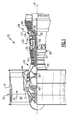
- FIG. 1 schematically illustrates a gas turbine engine 20.
- the gas turbine engine 20 is disclosed herein as a two-spool turbofan that generally incorporates a fan section 22, a compressor section 24, a combustor section 26 and a turbine section 28.
- Alternative engines might include an augmentor section (not shown) among other systems or features.
- the fan section 22 drives air along a bypass flow path B in a bypass duct defined within a nacelle 15, while the compressor section 24 drives air along a core flow path C for compression and communication into the combustor section 26 then expansion through the turbine section 28.
- the exemplary engine 20 generally includes a low speed spool 30 and a high speed spool 32 mounted for rotation about an engine central longitudinal axis A relative to an engine static structure 36 via several bearing systems 38. It should be understood that various bearing systems 38 at various locations may alternatively or additionally be provided, and the location of bearing systems 38 may be varied as appropriate to the application.
- the low speed spool 30 generally includes an inner shaft 40 that interconnects a fan 42, a first (or low) pressure compressor 44 and a first (or low) pressure turbine 46.
- the inner shaft 40 is connected to the fan 42 through a speed change mechanism, which in exemplary gas turbine engine 20 is illustrated as a geared architecture 48 to drive the fan 42 at a lower speed than the low speed spool 30.
- the high speed spool 32 includes an outer shaft 50 that interconnects a second (or high) pressure compressor 52 and a second (or high) pressure turbine 54.
- a combustor 56 is arranged in exemplary gas turbine 20 between the high pressure compressor 52 and the high pressure turbine 54.
- a mid-turbine frame 57 of the engine static structure 36 is arranged generally between the high pressure turbine 54 and the low pressure turbine 46.
- the mid-turbine frame 57 further supports bearing systems 38 in the turbine section 28.
- the inner shaft 40 and the outer shaft 50 are concentric and rotate via bearing systems 38 about the engine central longitudinal axis A which is collinear with their longitudinal axes.
- the core airflow is compressed by the low pressure compressor 44 then the high pressure compressor 52, mixed and burned with fuel in the combustor 56, then expanded over the high pressure turbine 54 and low pressure turbine 46.
- the mid-turbine frame 57 includes airfoils 59 which are in the core airflow path C.
- the turbines 46, 54 rotationally drive the respective low speed spool 30 and high speed spool 32 in response to the expansion.
- gear system 48 may be located aft of combustor section 26 or even aft of turbine section 28, and fan section 22 may be positioned forward or aft of the location of gear system 48.
- the engine 20 in one example is a high-bypass geared aircraft engine.
- the engine 20 bypass ratio is greater than about six (6), with an example embodiment being greater than about ten (10)
- the geared architecture 48 is an epicyclic gear train, such as a planetary gear system or other gear system, with a gear reduction ratio of greater than about 2.3
- the low pressure turbine 46 has a pressure ratio that is greater than about five.
- the engine 20 bypass ratio is greater than about ten (10:1)
- the fan diameter is significantly larger than that of the low pressure compressor 44
- the low pressure turbine 46 has a pressure ratio that is greater than about five 5:1.
- Low pressure turbine 46 pressure ratio is pressure measured prior to inlet of low pressure turbine 46 as related to the pressure at the outlet of the low pressure turbine 46 prior to an exhaust nozzle.
- the geared architecture 48 may be an epicycle gear train, such as a planetary gear system or other gear system, with a gear reduction ratio of greater than about 2.3:1. It should be understood, however, that the above parameters are only exemplary of one embodiment of a geared architecture engine and that the present invention is applicable to other gas turbine engines including direct drive turbofans.
- the fan section 22 of the engine 20 is designed for a particular flight condition -- typically cruise at about 0.8 Mach and about 35,000 feet.
- the flight condition of 0.8 Mach and 35,000 ft (10,668 meters), with the engine at its best fuel consumption - also known as "bucket cruise Thrust Specific Fuel Consumption ('TSFC')" - is the industry standard parameter of lbm of fuel being burned divided by lbf of thrust the engine produces at that minimum point.
- “Low fan pressure ratio” is the pressure ratio across the fan blade alone, without a Fan Exit Guide Vane (“FEGV”) system.
- the low fan pressure ratio as disclosed herein according to one non-limiting embodiment is less than about 1.45.
- Low corrected fan tip speed is the actual fan tip speed in ft/sec divided by an industry standard temperature correction of [(Tram °R) / (518.7 °R)] 0.5 .
- the "Low corrected fan tip speed” as disclosed herein according to one non-limiting embodiment is less than about 1150 ft / second (350.5 meters/second).
- a rotor hub 60 of the turbine section 28 includes multiple rotor lugs 62 spaced around a circumference of the rotor hub 60.
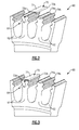
- a heat shield 70 slidably engages each of the rotor lugs 62 between a first position partially engaging the rotor lug 62 ( Figure 2 ) and a second position ( Figure 3 ) fully engaging the rotor lug 62.
- the heat shield 70 is located on a distal end of the rotor lugs 62.
- the heat shield 70 reflects heat from the rotor blades 66 ( Fig. 4 ) and hot gases passing through the turbine section 28 to reduce the temperature of the rotor hub 60.
- the heat shield 70 includes a generally planar portion 71 with a first longitudinal hook 72a on a first side of the planar portion 71 and a second longitudinal hook 72b on an opposite second side of the planar portion 71. Since the heat shield 70 is formed from a single piece of material that is substantially planar, the heat shield 70 has a substantially constant thickness.
- Each of the lugs 62 includes a first rail 74a and a second rail 74b on the distal end of the rotor lug 62.
- the heat shield 70 is retained adjacent the distal end of the rotor lug 62 by engaging the first longitudinal hook 72a with the first rail 74a and the second longitudinal hook 72b with a second rail 74b.
- the first and second longitudinal hooks 72a and 72b and the first and second rails 74a and 74b are unbroken without any discontinuities and the first and second longitudinal hooks 72a and 72b have a fillet radius between approximately 0.030 inches (0.762 mm) and 0.090 inches (2.286 mm).
- the first and second longitudinal hooks 72a and 72b include a non-circular fillet.
- the first and second rails 74a and 74b extend radially upward and outward from the distal end of rotor lugs 62.
- the rotor lug 62 (including the first and second rails 74a and 74b) and the heat shield 70 define a channel 76.
- the channel 76 in the illustrated example includes a generally trapezoidal cross section, other shapes such as rectangular or elliptical cross sections could be incorporated.
- the channel 76 is in fluid communication with bleed air from the compressor section 24 to cool the rotor lugs 62 along with the rotor hub 60.
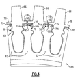
- the lugs 62 may include protrusions 80 (e.g., structure integrally formed with or separately attached to the lugs 62) extending into the channel 76 to increase the turbulence of the bleed air flowing through the channel 76 and the convective heat transfer between the bleed air and the rotor hub 62. ( Figure 4 ).
- the protrusions 80 may be attached to the rotor lugs 62 or the heat shield 76.
- rotor blades 66 are located on opposing sides of the rotor lug 62 and generally cover the heat shield 70.
- the rotor lugs 62 have a general "fir-tree" shape 64 for retaining complementary shaped protrusions 68 on the rotor blades 66
- a platform section 78 on opposing sides of each of the rotor blades 66 is adjacent the heat shields 70 on adjacent rotor lugs 62.
- the centrifugal pull from a heat shield on the rotor blade 66 due to the increased weight from the heat shield will be eliminated because the load from the heat shield 70 will be carried by the rotor hub 60 instead of the rotor blades 66.
- This will also allow traditional support material, such as seal shelves from the base portion of the rotor blades 66 to be removed. Removal of the traditional support material reduces the centrifugal load experienced by a neck portion of the rotor blades 66.
Landscapes
- Engineering & Computer Science (AREA)
- Mechanical Engineering (AREA)
- General Engineering & Computer Science (AREA)
- Life Sciences & Earth Sciences (AREA)
- Sustainable Development (AREA)
- Structures Of Non-Positive Displacement Pumps (AREA)
Abstract
Description
- A gas turbine engine typically includes a fan section, a compressor section, a combustor section, and a turbine section. Air entering the compressor section is compressed and delivered into the combustion section where it is mixed with fuel and ignited to generate a high-speed exhaust gas flow. The high-speed exhaust gas flow expands through the turbine section to drive the compressor and the fan section.
- Rotors in gas turbine engines have multiple rotor lugs that form slots for accepting blades. The slots include protrusions that engage complementary protrusions on each of the blades to retain the blades in the slots. During operation of the gas turbine engine, the rotors are subjected to substantial centrifugal forces and extreme temperatures from hot gases passing through and expanding in the turbine section. As the duration of operation and the temperature of the gases passing through the turbine section increases, a temperature of the blades and the rotor becomes elevated. Therefore, there is a need to cool portions of the turbine section.
- In one exemplary embodiment, an assembly for a gas turbine engine that includes a fan section. A turbine section is configured to drive the fan section. The turbine section includes a rotor hub with a rotor lug. A heat shield engages the rotor lug. The heat shield and the rotor lug define a cooling passage.
- In a further embodiment of the above, the assembly includes at least one turbulent structure rotor lug that is configured to increase turbulence of a cooling fluid flowing through the cooling passage.
- In a further embodiment of any of the above, at least one turbulent structure is integrally formed with the rotor lug.
- In a further embodiment of any of the above, there is a compressor section with a bleed air source for providing a cooling fluid to the cooling passage.
- In a further embodiment of any of the above, the rotor lug includes at least one rail located on a distal end thereof.
- In a further embodiment of any of the above, the rotor lug includes a first rail and a second rail that extends from a distal end of the rotor lug.
- In a further embodiment of any of the above, the heat shield includes a first hook to slidably engage the first rail and a second hook to slidably engage the second rail.
- In a further embodiment of any of the above, the first hook and the second hook have a fillet radius between approximately 0.030 inches (0.762 mm) and 0.090 inches (2.286 mm).
- In a further embodiment of any of the above, the first hook and the second hook have a non-circular fillet.
- In a further embodiment of any of the above, the heat shield slidably engages the rotor hub.
- In another exemplary embodiment, a rotor for a gas turbine engine includes a rotor hub including at least one rotor lug. A heat shield engages the at least one rotor lug. The heat shield and the rotor lug define a cooling passage.
- In a further embodiment of the above, at least one turbulent structure is coupled to the lug and is configured to increase turbulence of a cooling fluid that flows through the cooling passage.
- In a further embodiment of any of the above, at least one turbulent structure is located on at least one of the rotor hub or the heat shield.
- In a further embodiment of any of the above, the lug includes a first rail and a second rail that extend from a radially outer end thereof.
- In a further embodiment of any of the above, the heat shield includes a first hook to engage the first rail and a second hook to engage the second rail.
- In a further embodiment of any of the above, the first hook and the second hook have a fillet radius between approximately 0.030 inches (0.762 mm) and 0.090 inches (2.286 mm).
- In a further embodiment of any of the above, the heat shield slidably engages the first rail and the second rail.
- In another exemplary embodiment, a method of cooling a rotor hub includes shielding heat from a rotor hub with a heat shield and directing a cooling fluid into a cooling passage defined between the rotor hub and the heat shield.
- In a further embodiment of the above, the heat shield is mounted on a distal end of the rotor hub on a rotor lug.
- In a further embodiment of any of the above, the rotor lug includes a first rail to engage a first longitudinal hook on the heat shield and a second rail to engage a second longitudinal hook on the heat shield.
- In a further embodiment of any of the above, the cooling passage includes at least one turbulent structure that is configured to increase the turbulence of the cooling fluid.
- In a further embodiment of any of the above, the method includes reflecting heat form the rotor hub with the heat shield.
- The various features and advantages of this disclosure will become apparent to those skilled in the art from the following detailed description. The drawings that accompany the detailed description can be briefly described as follows.
-
-
Figure 1 illustrates a schematic view of a gas turbine engine. -
Figure 2 illustrates a perspective view of a heat shield in a first position relative to a rotor hub. -
Figure 3 illustrates a perspective view of the heat shield ofFigure 2 in a second position relative to the rotor hub. -
Figure 4 illustrates an end view of the rotor hub and heat shield ofFigure 3 . -
Figure 1 schematically illustrates agas turbine engine 20. Thegas turbine engine 20 is disclosed herein as a two-spool turbofan that generally incorporates afan section 22, acompressor section 24, acombustor section 26 and aturbine section 28. Alternative engines might include an augmentor section (not shown) among other systems or features. Thefan section 22 drives air along a bypass flow path B in a bypass duct defined within anacelle 15, while thecompressor section 24 drives air along a core flow path C for compression and communication into thecombustor section 26 then expansion through theturbine section 28. Although depicted as a two-spool turbofan gas turbine engine in the disclosed non-limiting embodiment, it should be understood that the concepts described herein are not limited to use with two-spool turbofans as the teachings may be applied to other types of turbine engines including three-spool architectures. - The
exemplary engine 20 generally includes alow speed spool 30 and ahigh speed spool 32 mounted for rotation about an engine central longitudinal axis A relative to an enginestatic structure 36 viaseveral bearing systems 38. It should be understood thatvarious bearing systems 38 at various locations may alternatively or additionally be provided, and the location ofbearing systems 38 may be varied as appropriate to the application. - The
low speed spool 30 generally includes aninner shaft 40 that interconnects afan 42, a first (or low) pressure compressor 44 and a first (or low)pressure turbine 46. Theinner shaft 40 is connected to thefan 42 through a speed change mechanism, which in exemplarygas turbine engine 20 is illustrated as a gearedarchitecture 48 to drive thefan 42 at a lower speed than thelow speed spool 30. Thehigh speed spool 32 includes anouter shaft 50 that interconnects a second (or high)pressure compressor 52 and a second (or high)pressure turbine 54. Acombustor 56 is arranged inexemplary gas turbine 20 between thehigh pressure compressor 52 and thehigh pressure turbine 54. Amid-turbine frame 57 of the enginestatic structure 36 is arranged generally between thehigh pressure turbine 54 and thelow pressure turbine 46. Themid-turbine frame 57 further supports bearingsystems 38 in theturbine section 28. Theinner shaft 40 and theouter shaft 50 are concentric and rotate viabearing systems 38 about the engine central longitudinal axis A which is collinear with their longitudinal axes. - The core airflow is compressed by the low pressure compressor 44 then the
high pressure compressor 52, mixed and burned with fuel in thecombustor 56, then expanded over thehigh pressure turbine 54 andlow pressure turbine 46. Themid-turbine frame 57 includesairfoils 59 which are in the core airflow path C. Theturbines low speed spool 30 andhigh speed spool 32 in response to the expansion. It will be appreciated that each of the positions of thefan section 22,compressor section 24,combustor section 26,turbine section 28, and fandrive gear system 48 may be varied. For example,gear system 48 may be located aft ofcombustor section 26 or even aft ofturbine section 28, andfan section 22 may be positioned forward or aft of the location ofgear system 48. - The
engine 20 in one example is a high-bypass geared aircraft engine. In a further example, theengine 20 bypass ratio is greater than about six (6), with an example embodiment being greater than about ten (10), the gearedarchitecture 48 is an epicyclic gear train, such as a planetary gear system or other gear system, with a gear reduction ratio of greater than about 2.3 and thelow pressure turbine 46 has a pressure ratio that is greater than about five. In one disclosed embodiment, theengine 20 bypass ratio is greater than about ten (10:1), the fan diameter is significantly larger than that of the low pressure compressor 44, and thelow pressure turbine 46 has a pressure ratio that is greater than about five 5:1.Low pressure turbine 46 pressure ratio is pressure measured prior to inlet oflow pressure turbine 46 as related to the pressure at the outlet of thelow pressure turbine 46 prior to an exhaust nozzle. The gearedarchitecture 48 may be an epicycle gear train, such as a planetary gear system or other gear system, with a gear reduction ratio of greater than about 2.3:1. It should be understood, however, that the above parameters are only exemplary of one embodiment of a geared architecture engine and that the present invention is applicable to other gas turbine engines including direct drive turbofans. - A significant amount of thrust is provided by the bypass flow B due to the high bypass ratio. The
fan section 22 of theengine 20 is designed for a particular flight condition -- typically cruise at about 0.8 Mach and about 35,000 feet. The flight condition of 0.8 Mach and 35,000 ft (10,668 meters), with the engine at its best fuel consumption - also known as "bucket cruise Thrust Specific Fuel Consumption ('TSFC')" - is the industry standard parameter of lbm of fuel being burned divided by lbf of thrust the engine produces at that minimum point. "Low fan pressure ratio" is the pressure ratio across the fan blade alone, without a Fan Exit Guide Vane ("FEGV") system. The low fan pressure ratio as disclosed herein according to one non-limiting embodiment is less than about 1.45. "Low corrected fan tip speed" is the actual fan tip speed in ft/sec divided by an industry standard temperature correction of [(Tram °R) / (518.7 °R)]0.5. The "Low corrected fan tip speed" as disclosed herein according to one non-limiting embodiment is less than about 1150 ft / second (350.5 meters/second). - As shown in
Figures 2 and 3 , arotor hub 60 of theturbine section 28 includes multiple rotor lugs 62 spaced around a circumference of therotor hub 60. Aheat shield 70 slidably engages each of the rotor lugs 62 between a first position partially engaging the rotor lug 62 (Figure 2 ) and a second position (Figure 3 ) fully engaging therotor lug 62. Theheat shield 70 is located on a distal end of the rotor lugs 62. - The
heat shield 70 reflects heat from the rotor blades 66 (Fig. 4 ) and hot gases passing through theturbine section 28 to reduce the temperature of therotor hub 60. Theheat shield 70 includes a generallyplanar portion 71 with a firstlongitudinal hook 72a on a first side of theplanar portion 71 and a secondlongitudinal hook 72b on an opposite second side of theplanar portion 71. Since theheat shield 70 is formed from a single piece of material that is substantially planar, theheat shield 70 has a substantially constant thickness. - Each of the
lugs 62 includes afirst rail 74a and asecond rail 74b on the distal end of therotor lug 62. Theheat shield 70 is retained adjacent the distal end of therotor lug 62 by engaging the firstlongitudinal hook 72a with thefirst rail 74a and the secondlongitudinal hook 72b with asecond rail 74b. In the illustrated example, the first and secondlongitudinal hooks second rails longitudinal hooks longitudinal hooks - The first and
second rails second rails heat shield 70 define achannel 76. Although thechannel 76 in the illustrated example includes a generally trapezoidal cross section, other shapes such as rectangular or elliptical cross sections could be incorporated. - The
channel 76 is in fluid communication with bleed air from thecompressor section 24 to cool the rotor lugs 62 along with therotor hub 60. As shown inFig. 4 , thelugs 62 may include protrusions 80 (e.g., structure integrally formed with or separately attached to the lugs 62) extending into thechannel 76 to increase the turbulence of the bleed air flowing through thechannel 76 and the convective heat transfer between the bleed air and therotor hub 62. (Figure 4 ). Theprotrusions 80 may be attached to the rotor lugs 62 or theheat shield 76. - As shown in
Figure 4 ,rotor blades 66 are located on opposing sides of therotor lug 62 and generally cover theheat shield 70. The rotor lugs 62 have a general "fir-tree"shape 64 for retaining complementary shapedprotrusions 68 on the rotor blades 66A platform section 78 on opposing sides of each of therotor blades 66 is adjacent theheat shields 70 on adjacent rotor lugs 62. - By shielding the
rotor hub 60 from excess heat and cooling it with bleed air passing through thechannel 76, material from therotor hub 60 can be removed because material strength is higher at lower temperatures. - Additionally, by attaching the
heat shield 70 to therotor hub 60 instead of therotor blade 66, the centrifugal pull from a heat shield on therotor blade 66 due to the increased weight from the heat shield will be eliminated because the load from theheat shield 70 will be carried by therotor hub 60 instead of therotor blades 66. This will also allow traditional support material, such as seal shelves from the base portion of therotor blades 66 to be removed. Removal of the traditional support material reduces the centrifugal load experienced by a neck portion of therotor blades 66. - The preceding description is exemplary rather than limiting in nature. Variations and modifications to the disclosed examples may become apparent to those skilled in the art that do not necessarily depart from the essence of this disclosure. The scope of legal protection given to this disclosure can only be determined by studying the following claims.
Claims (15)
- A rotor for a gas turbine engine, comprising:a rotor hub (60) including at least one rotor lug (62); anda heat shield (70) engaging the at least one rotor lug (62),wherein the heat shield (70) and the rotor lug (62) define a cooling passage (76).
- The rotor of claim 1, further comprising at least one turbulent structure (80) coupled to the lug (62) and configured to increase turbulence of a cooling fluid flowing through the cooling passage (76).
- The rotor of claim 2, wherein the at least one turbulent structure (80) is located on at least one of the rotor hub (62) or the heat shield (70).
- The rotor of claim 3, wherein the at least one turbulent structure (80) is integrally formed with the rotor lug (62).
- The rotor of any preceding claim, wherein the lug (62) includes a first rail (74a) and a second rail (74b) extending from a radially outer end thereof.
- The rotor of claim 5, wherein the heat shield (70) includes a first hook (72a) for engaging the first rail (74a) and a second hook (72b) for engaging the second rail (74b).
- The rotor of claim 6, wherein the first hook (72a) and the second hook (72b) have a fillet radius between approximately 0.030 inches (0.762 mm) and 0.090 inches (2.286 mm).
- The rotor of claim 6, wherein the first hook (72a) and the second hook (72b) have a non-circular fillet.
- The rotor of any preceding claim, wherein the heat shield (70) slidably engages the rotor hub (62).
- The rotor of claim 9 as dependent upon any of claims 5 to 8, wherein the heat shield (70) slidably engages the first rail (74a) and the second rail (74b).
- An assembly for a gas turbine engine (20), the assembly comprising:a fan section (22);a turbine section (28) configured to drive the fan section (22), the turbine section (28) including a rotor as claimed in any preceding claim.
- The assembly of claim 11, further comprising a compressor section (24) with a bleed air source for providing a cooling fluid to the cooling passage (76).
- A method of cooling a rotor hub (62), comprising:a) shielding heat from a rotor hub (62) with a heat shield (70); andb) directing a cooling fluid into a cooling passage (76) defined between the rotor hub (62) and the heat shield (70).
- The method of claim 13, wherein the cooling passage (76) includes at least one turbulent structure (80) configured to increase the turbulence of the cooling fluid.
- The method of claim 13 or 14, further including reflecting heat from the rotor hub (62) with the heat shield (70).
Applications Claiming Priority (1)
| Application Number | Priority Date | Filing Date | Title |
|---|---|---|---|
| US201462001782P | 2014-05-22 | 2014-05-22 |
Publications (2)
| Publication Number | Publication Date |
|---|---|
| EP2947268A1 true EP2947268A1 (en) | 2015-11-25 |
| EP2947268B1 EP2947268B1 (en) | 2022-01-05 |
Family
ID=53510576
Family Applications (1)
| Application Number | Title | Priority Date | Filing Date |
|---|---|---|---|
| EP15168238.2A Not-in-force EP2947268B1 (en) | 2014-05-22 | 2015-05-19 | Rotor heat shield for a lug of a rotor of a gas turbine engine |
Country Status (2)
| Country | Link |
|---|---|
| US (1) | US9920627B2 (en) |
| EP (1) | EP2947268B1 (en) |
Cited By (2)
| Publication number | Priority date | Publication date | Assignee | Title |
|---|---|---|---|---|
| US20180128114A1 (en) * | 2016-11-10 | 2018-05-10 | Doosan Heavy Industries & Construction Co., Ltd | Structure for cooling rotor of turbomachine, rotor and turbomachine having the same |
| GB2629219A (en) * | 2023-04-20 | 2024-10-23 | Siemens Energy Global Gmbh & Co Kg | A heat shield for a rotor of a turbo engine |
Families Citing this family (2)
| Publication number | Priority date | Publication date | Assignee | Title |
|---|---|---|---|---|
| USD786419S1 (en) * | 2016-05-16 | 2017-05-09 | Kewaunee Scientific Corporation | Baffle for fume hoods |
| US11021961B2 (en) | 2018-12-05 | 2021-06-01 | General Electric Company | Rotor assembly thermal attenuation structure and system |
Citations (2)
| Publication number | Priority date | Publication date | Assignee | Title |
|---|---|---|---|---|
| US3266771A (en) * | 1963-12-16 | 1966-08-16 | Rolls Royce | Turbines and compressors |
| EP2578803A2 (en) * | 2011-10-07 | 2013-04-10 | General Electric Company | Methods and systems for use in regulating a temperature of components |
Family Cites Families (22)
| Publication number | Priority date | Publication date | Assignee | Title |
|---|---|---|---|---|
| BE540433A (en) * | 1954-08-12 | |||
| US3709631A (en) * | 1971-03-18 | 1973-01-09 | Caterpillar Tractor Co | Turbine blade seal arrangement |
| FR2503247B1 (en) * | 1981-04-07 | 1985-06-14 | Snecma | IMPROVEMENTS ON THE FLOORS OF A GAS TURBINE OF TURBOREACTORS PROVIDED WITH AIR COOLING MEANS OF THE TURBINE WHEEL DISC |
| FR2517779B1 (en) * | 1981-12-03 | 1986-06-13 | Snecma | DEVICE FOR DAMPING THE BLADES OF A TURBOMACHINE BLOWER |
| US4470757A (en) | 1982-02-25 | 1984-09-11 | United Technologies Corporation | Sideplate retention for a turbine rotor |
| US4439107A (en) | 1982-09-16 | 1984-03-27 | United Technologies Corporation | Rotor blade cooling air chamber |
| US4507052A (en) | 1983-03-31 | 1985-03-26 | General Motors Corporation | End seal for turbine blade bases |
| US4505642A (en) | 1983-10-24 | 1985-03-19 | United Technologies Corporation | Rotor blade interplatform seal |
| US4505640A (en) | 1983-12-13 | 1985-03-19 | United Technologies Corporation | Seal means for a blade attachment slot of a rotor assembly |
| US4536129A (en) | 1984-06-15 | 1985-08-20 | United Technologies Corporation | Turbine blade with disk rim shield |
| US4659285A (en) | 1984-07-23 | 1987-04-21 | United Technologies Corporation | Turbine cover-seal assembly |
| US4875830A (en) * | 1985-07-18 | 1989-10-24 | United Technologies Corporation | Flanged ladder seal |
| US5201849A (en) | 1990-12-10 | 1993-04-13 | General Electric Company | Turbine rotor seal body |
| US5339619A (en) | 1992-08-31 | 1994-08-23 | United Technologies Corporation | Active cooling of turbine rotor assembly |
| US5217348A (en) | 1992-09-24 | 1993-06-08 | United Technologies Corporation | Turbine vane assembly with integrally cast cooling fluid nozzle |
| US5281097A (en) * | 1992-11-20 | 1994-01-25 | General Electric Company | Thermal control damper for turbine rotors |
| US5388962A (en) | 1993-10-15 | 1995-02-14 | General Electric Company | Turbine rotor disk post cooling system |
| FR2726323B1 (en) * | 1994-10-26 | 1996-12-13 | Snecma | ASSEMBLY OF A ROTARY DISC AND BLADES, ESPECIALLY USED IN A TURBOMACHINE |
| US5630703A (en) | 1995-12-15 | 1997-05-20 | General Electric Company | Rotor disk post cooling system |
| US6315298B1 (en) * | 1999-11-22 | 2001-11-13 | United Technologies Corporation | Turbine disk and blade assembly seal |
| GB2411697B (en) * | 2004-03-06 | 2006-06-21 | Rolls Royce Plc | A turbine having a cooling arrangement |
| US9347325B2 (en) * | 2012-10-31 | 2016-05-24 | Solar Turbines Incorporated | Damper for a turbine rotor assembly |
-
2015
- 2015-05-15 US US14/712,988 patent/US9920627B2/en not_active Expired - Fee Related
- 2015-05-19 EP EP15168238.2A patent/EP2947268B1/en not_active Not-in-force
Patent Citations (2)
| Publication number | Priority date | Publication date | Assignee | Title |
|---|---|---|---|---|
| US3266771A (en) * | 1963-12-16 | 1966-08-16 | Rolls Royce | Turbines and compressors |
| EP2578803A2 (en) * | 2011-10-07 | 2013-04-10 | General Electric Company | Methods and systems for use in regulating a temperature of components |
Cited By (6)
| Publication number | Priority date | Publication date | Assignee | Title |
|---|---|---|---|---|
| US20180128114A1 (en) * | 2016-11-10 | 2018-05-10 | Doosan Heavy Industries & Construction Co., Ltd | Structure for cooling rotor of turbomachine, rotor and turbomachine having the same |
| EP3321471A1 (en) * | 2016-11-10 | 2018-05-16 | Doosan Heavy Industries & Construction Co., Ltd. | Structure for cooling rotor of turbomachine, rotor and turbomachine having the same |
| JP2018076862A (en) * | 2016-11-10 | 2018-05-17 | ドゥサン ヘヴィー インダストリーズ アンド コンストラクション カンパニー リミテッド | Rotating body cooling structure and rotor and turbomachine including the same |
| KR20180052426A (en) * | 2016-11-10 | 2018-05-18 | 두산중공업 주식회사 | Structure for cooling turbine's rotor part |
| US10837290B2 (en) * | 2016-11-10 | 2020-11-17 | DOOSAN Heavy Industries Construction Co., LTD | Structure for cooling rotor of turbomachine, rotor and turbomachine having the same |
| GB2629219A (en) * | 2023-04-20 | 2024-10-23 | Siemens Energy Global Gmbh & Co Kg | A heat shield for a rotor of a turbo engine |
Also Published As
| Publication number | Publication date |
|---|---|
| US20160376892A1 (en) | 2016-12-29 |
| EP2947268B1 (en) | 2022-01-05 |
| US9920627B2 (en) | 2018-03-20 |
Similar Documents
| Publication | Publication Date | Title |
|---|---|---|
| US9920633B2 (en) | Compound fillet for a gas turbine airfoil | |
| EP2927433B1 (en) | Active clearance control for gas turbine engine | |
| US9863259B2 (en) | Chordal seal | |
| US20160169004A1 (en) | Cooling passages for gas turbine engine component | |
| US10024172B2 (en) | Gas turbine engine airfoil | |
| EP3009616A1 (en) | Gas turbine component with platform cooling | |
| EP2947268B1 (en) | Rotor heat shield for a lug of a rotor of a gas turbine engine | |
| EP3054093B1 (en) | Arrangement of trip strips | |
| EP3051066A1 (en) | Staggerd casting core extensions | |
| EP3101236B1 (en) | Trailing edge platform seals | |
| EP3043030B1 (en) | Anti-rotation vane | |
| EP3246535B1 (en) | Turbine vane gusset | |
| US20180038236A1 (en) | Gas turbine engine stator vane baffle arrangement | |
| US20160326909A1 (en) | Gas turbine engine component with separation rib for cooling passages | |
| US10954796B2 (en) | Rotor bore conditioning for a gas turbine engine | |
| US10422232B2 (en) | Component for a gas turbine engine | |
| EP3181869A1 (en) | Compressor core inner diameter cooling | |
| EP3095967A1 (en) | Support assembly for a gas turbine engine | |
| EP3392472A1 (en) | Compressor section for a gas turbine engine, corresponding gas turbine engine and method of operating a compressor section in a gas turbine engine |
Legal Events
| Date | Code | Title | Description |
|---|---|---|---|
| PUAI | Public reference made under article 153(3) epc to a published international application that has entered the european phase |
Free format text: ORIGINAL CODE: 0009012 |
|
| AK | Designated contracting states |
Kind code of ref document: A1 Designated state(s): AL AT BE BG CH CY CZ DE DK EE ES FI FR GB GR HR HU IE IS IT LI LT LU LV MC MK MT NL NO PL PT RO RS SE SI SK SM TR |
|
| AX | Request for extension of the european patent |
Extension state: BA ME |
|
| 17P | Request for examination filed |
Effective date: 20160525 |
|
| RBV | Designated contracting states (corrected) |
Designated state(s): AL AT BE BG CH CY CZ DE DK EE ES FI FR GB GR HR HU IE IS IT LI LT LU LV MC MK MT NL NO PL PT RO RS SE SI SK SM TR |
|
| RAP1 | Party data changed (applicant data changed or rights of an application transferred) |
Owner name: UNITED TECHNOLOGIES CORPORATION |
|
| STAA | Information on the status of an ep patent application or granted ep patent |
Free format text: STATUS: EXAMINATION IS IN PROGRESS |
|
| 17Q | First examination report despatched |
Effective date: 20200409 |
|
| RAP1 | Party data changed (applicant data changed or rights of an application transferred) |
Owner name: RAYTHEON TECHNOLOGIES CORPORATION |
|
| RIC1 | Information provided on ipc code assigned before grant |
Ipc: F01D 11/00 20060101ALN20210609BHEP Ipc: F01D 5/08 20060101AFI20210609BHEP |
|
| GRAP | Despatch of communication of intention to grant a patent |
Free format text: ORIGINAL CODE: EPIDOSNIGR1 |
|
| STAA | Information on the status of an ep patent application or granted ep patent |
Free format text: STATUS: GRANT OF PATENT IS INTENDED |
|
| INTG | Intention to grant announced |
Effective date: 20210721 |
|
| GRAS | Grant fee paid |
Free format text: ORIGINAL CODE: EPIDOSNIGR3 |
|
| GRAA | (expected) grant |
Free format text: ORIGINAL CODE: 0009210 |
|
| STAA | Information on the status of an ep patent application or granted ep patent |
Free format text: STATUS: THE PATENT HAS BEEN GRANTED |
|
| AK | Designated contracting states |
Kind code of ref document: B1 Designated state(s): AL AT BE BG CH CY CZ DE DK EE ES FI FR GB GR HR HU IE IS IT LI LT LU LV MC MK MT NL NO PL PT RO RS SE SI SK SM TR |
|
| REG | Reference to a national code |
Ref country code: GB Ref legal event code: FG4D |
|
| REG | Reference to a national code |
Ref country code: CH Ref legal event code: EP |
|
| REG | Reference to a national code |
Ref country code: AT Ref legal event code: REF Ref document number: 1460776 Country of ref document: AT Kind code of ref document: T Effective date: 20220115 |
|
| REG | Reference to a national code |
Ref country code: DE Ref legal event code: R096 Ref document number: 602015076189 Country of ref document: DE |
|
| REG | Reference to a national code |
Ref country code: IE Ref legal event code: FG4D |
|
| REG | Reference to a national code |
Ref country code: LT Ref legal event code: MG9D |
|
| REG | Reference to a national code |
Ref country code: NL Ref legal event code: MP Effective date: 20220105 |
|
| REG | Reference to a national code |
Ref country code: AT Ref legal event code: MK05 Ref document number: 1460776 Country of ref document: AT Kind code of ref document: T Effective date: 20220105 |
|
| PG25 | Lapsed in a contracting state [announced via postgrant information from national office to epo] |
Ref country code: NL Free format text: LAPSE BECAUSE OF FAILURE TO SUBMIT A TRANSLATION OF THE DESCRIPTION OR TO PAY THE FEE WITHIN THE PRESCRIBED TIME-LIMIT Effective date: 20220105 |
|
| PG25 | Lapsed in a contracting state [announced via postgrant information from national office to epo] |
Ref country code: SE Free format text: LAPSE BECAUSE OF FAILURE TO SUBMIT A TRANSLATION OF THE DESCRIPTION OR TO PAY THE FEE WITHIN THE PRESCRIBED TIME-LIMIT Effective date: 20220105 Ref country code: RS Free format text: LAPSE BECAUSE OF FAILURE TO SUBMIT A TRANSLATION OF THE DESCRIPTION OR TO PAY THE FEE WITHIN THE PRESCRIBED TIME-LIMIT Effective date: 20220105 Ref country code: PT Free format text: LAPSE BECAUSE OF FAILURE TO SUBMIT A TRANSLATION OF THE DESCRIPTION OR TO PAY THE FEE WITHIN THE PRESCRIBED TIME-LIMIT Effective date: 20220505 Ref country code: NO Free format text: LAPSE BECAUSE OF FAILURE TO SUBMIT A TRANSLATION OF THE DESCRIPTION OR TO PAY THE FEE WITHIN THE PRESCRIBED TIME-LIMIT Effective date: 20220405 Ref country code: LT Free format text: LAPSE BECAUSE OF FAILURE TO SUBMIT A TRANSLATION OF THE DESCRIPTION OR TO PAY THE FEE WITHIN THE PRESCRIBED TIME-LIMIT Effective date: 20220105 Ref country code: HR Free format text: LAPSE BECAUSE OF FAILURE TO SUBMIT A TRANSLATION OF THE DESCRIPTION OR TO PAY THE FEE WITHIN THE PRESCRIBED TIME-LIMIT Effective date: 20220105 Ref country code: ES Free format text: LAPSE BECAUSE OF FAILURE TO SUBMIT A TRANSLATION OF THE DESCRIPTION OR TO PAY THE FEE WITHIN THE PRESCRIBED TIME-LIMIT Effective date: 20220105 Ref country code: BG Free format text: LAPSE BECAUSE OF FAILURE TO SUBMIT A TRANSLATION OF THE DESCRIPTION OR TO PAY THE FEE WITHIN THE PRESCRIBED TIME-LIMIT Effective date: 20220405 |
|
| PG25 | Lapsed in a contracting state [announced via postgrant information from national office to epo] |
Ref country code: PL Free format text: LAPSE BECAUSE OF FAILURE TO SUBMIT A TRANSLATION OF THE DESCRIPTION OR TO PAY THE FEE WITHIN THE PRESCRIBED TIME-LIMIT Effective date: 20220105 Ref country code: LV Free format text: LAPSE BECAUSE OF FAILURE TO SUBMIT A TRANSLATION OF THE DESCRIPTION OR TO PAY THE FEE WITHIN THE PRESCRIBED TIME-LIMIT Effective date: 20220105 Ref country code: GR Free format text: LAPSE BECAUSE OF FAILURE TO SUBMIT A TRANSLATION OF THE DESCRIPTION OR TO PAY THE FEE WITHIN THE PRESCRIBED TIME-LIMIT Effective date: 20220406 Ref country code: FI Free format text: LAPSE BECAUSE OF FAILURE TO SUBMIT A TRANSLATION OF THE DESCRIPTION OR TO PAY THE FEE WITHIN THE PRESCRIBED TIME-LIMIT Effective date: 20220105 Ref country code: AT Free format text: LAPSE BECAUSE OF FAILURE TO SUBMIT A TRANSLATION OF THE DESCRIPTION OR TO PAY THE FEE WITHIN THE PRESCRIBED TIME-LIMIT Effective date: 20220105 |
|
| PG25 | Lapsed in a contracting state [announced via postgrant information from national office to epo] |
Ref country code: IS Free format text: LAPSE BECAUSE OF FAILURE TO SUBMIT A TRANSLATION OF THE DESCRIPTION OR TO PAY THE FEE WITHIN THE PRESCRIBED TIME-LIMIT Effective date: 20220505 |
|
| REG | Reference to a national code |
Ref country code: DE Ref legal event code: R097 Ref document number: 602015076189 Country of ref document: DE |
|
| PG25 | Lapsed in a contracting state [announced via postgrant information from national office to epo] |
Ref country code: SM Free format text: LAPSE BECAUSE OF FAILURE TO SUBMIT A TRANSLATION OF THE DESCRIPTION OR TO PAY THE FEE WITHIN THE PRESCRIBED TIME-LIMIT Effective date: 20220105 Ref country code: SK Free format text: LAPSE BECAUSE OF FAILURE TO SUBMIT A TRANSLATION OF THE DESCRIPTION OR TO PAY THE FEE WITHIN THE PRESCRIBED TIME-LIMIT Effective date: 20220105 Ref country code: RO Free format text: LAPSE BECAUSE OF FAILURE TO SUBMIT A TRANSLATION OF THE DESCRIPTION OR TO PAY THE FEE WITHIN THE PRESCRIBED TIME-LIMIT Effective date: 20220105 Ref country code: EE Free format text: LAPSE BECAUSE OF FAILURE TO SUBMIT A TRANSLATION OF THE DESCRIPTION OR TO PAY THE FEE WITHIN THE PRESCRIBED TIME-LIMIT Effective date: 20220105 Ref country code: DK Free format text: LAPSE BECAUSE OF FAILURE TO SUBMIT A TRANSLATION OF THE DESCRIPTION OR TO PAY THE FEE WITHIN THE PRESCRIBED TIME-LIMIT Effective date: 20220105 Ref country code: CZ Free format text: LAPSE BECAUSE OF FAILURE TO SUBMIT A TRANSLATION OF THE DESCRIPTION OR TO PAY THE FEE WITHIN THE PRESCRIBED TIME-LIMIT Effective date: 20220105 |
|
| PLBE | No opposition filed within time limit |
Free format text: ORIGINAL CODE: 0009261 |
|
| STAA | Information on the status of an ep patent application or granted ep patent |
Free format text: STATUS: NO OPPOSITION FILED WITHIN TIME LIMIT |
|
| PG25 | Lapsed in a contracting state [announced via postgrant information from national office to epo] |
Ref country code: AL Free format text: LAPSE BECAUSE OF FAILURE TO SUBMIT A TRANSLATION OF THE DESCRIPTION OR TO PAY THE FEE WITHIN THE PRESCRIBED TIME-LIMIT Effective date: 20220105 |
|
| 26N | No opposition filed |
Effective date: 20221006 |
|
| REG | Reference to a national code |
Ref country code: CH Ref legal event code: PL |
|
| REG | Reference to a national code |
Ref country code: BE Ref legal event code: MM Effective date: 20220531 |
|
| PG25 | Lapsed in a contracting state [announced via postgrant information from national office to epo] |
Ref country code: MC Free format text: LAPSE BECAUSE OF FAILURE TO SUBMIT A TRANSLATION OF THE DESCRIPTION OR TO PAY THE FEE WITHIN THE PRESCRIBED TIME-LIMIT Effective date: 20220105 Ref country code: LU Free format text: LAPSE BECAUSE OF NON-PAYMENT OF DUE FEES Effective date: 20220519 Ref country code: LI Free format text: LAPSE BECAUSE OF NON-PAYMENT OF DUE FEES Effective date: 20220531 Ref country code: CH Free format text: LAPSE BECAUSE OF NON-PAYMENT OF DUE FEES Effective date: 20220531 |
|
| PG25 | Lapsed in a contracting state [announced via postgrant information from national office to epo] |
Ref country code: SI Free format text: LAPSE BECAUSE OF FAILURE TO SUBMIT A TRANSLATION OF THE DESCRIPTION OR TO PAY THE FEE WITHIN THE PRESCRIBED TIME-LIMIT Effective date: 20220105 |
|
| PG25 | Lapsed in a contracting state [announced via postgrant information from national office to epo] |
Ref country code: IE Free format text: LAPSE BECAUSE OF NON-PAYMENT OF DUE FEES Effective date: 20220519 |
|
| PG25 | Lapsed in a contracting state [announced via postgrant information from national office to epo] |
Ref country code: BE Free format text: LAPSE BECAUSE OF NON-PAYMENT OF DUE FEES Effective date: 20220531 |
|
| P01 | Opt-out of the competence of the unified patent court (upc) registered |
Effective date: 20230520 |
|
| PG25 | Lapsed in a contracting state [announced via postgrant information from national office to epo] |
Ref country code: IT Free format text: LAPSE BECAUSE OF FAILURE TO SUBMIT A TRANSLATION OF THE DESCRIPTION OR TO PAY THE FEE WITHIN THE PRESCRIBED TIME-LIMIT Effective date: 20220105 |
|
| PG25 | Lapsed in a contracting state [announced via postgrant information from national office to epo] |
Ref country code: HU Free format text: LAPSE BECAUSE OF FAILURE TO SUBMIT A TRANSLATION OF THE DESCRIPTION OR TO PAY THE FEE WITHIN THE PRESCRIBED TIME-LIMIT; INVALID AB INITIO Effective date: 20150519 |
|
| PG25 | Lapsed in a contracting state [announced via postgrant information from national office to epo] |
Ref country code: MK Free format text: LAPSE BECAUSE OF FAILURE TO SUBMIT A TRANSLATION OF THE DESCRIPTION OR TO PAY THE FEE WITHIN THE PRESCRIBED TIME-LIMIT Effective date: 20220105 Ref country code: CY Free format text: LAPSE BECAUSE OF FAILURE TO SUBMIT A TRANSLATION OF THE DESCRIPTION OR TO PAY THE FEE WITHIN THE PRESCRIBED TIME-LIMIT Effective date: 20220105 |
|
| PG25 | Lapsed in a contracting state [announced via postgrant information from national office to epo] |
Ref country code: TR Free format text: LAPSE BECAUSE OF FAILURE TO SUBMIT A TRANSLATION OF THE DESCRIPTION OR TO PAY THE FEE WITHIN THE PRESCRIBED TIME-LIMIT Effective date: 20220105 |
|
| PGFP | Annual fee paid to national office [announced via postgrant information from national office to epo] |
Ref country code: GB Payment date: 20240418 Year of fee payment: 10 |
|
| PGFP | Annual fee paid to national office [announced via postgrant information from national office to epo] |
Ref country code: DE Payment date: 20240418 Year of fee payment: 10 |
|
| PGFP | Annual fee paid to national office [announced via postgrant information from national office to epo] |
Ref country code: FR Payment date: 20240418 Year of fee payment: 10 |
|
| PG25 | Lapsed in a contracting state [announced via postgrant information from national office to epo] |
Ref country code: MT Free format text: LAPSE BECAUSE OF FAILURE TO SUBMIT A TRANSLATION OF THE DESCRIPTION OR TO PAY THE FEE WITHIN THE PRESCRIBED TIME-LIMIT Effective date: 20220105 |
|
| REG | Reference to a national code |
Ref country code: DE Ref legal event code: R119 Ref document number: 602015076189 Country of ref document: DE |
|
| GBPC | Gb: european patent ceased through non-payment of renewal fee |
Effective date: 20250519 |
|
| PG25 | Lapsed in a contracting state [announced via postgrant information from national office to epo] |
Ref country code: GB Free format text: LAPSE BECAUSE OF NON-PAYMENT OF DUE FEES Effective date: 20250519 |
|
| PG25 | Lapsed in a contracting state [announced via postgrant information from national office to epo] |
Ref country code: DE Free format text: LAPSE BECAUSE OF NON-PAYMENT OF DUE FEES Effective date: 20251202 |
|
| PG25 | Lapsed in a contracting state [announced via postgrant information from national office to epo] |
Ref country code: FR Free format text: LAPSE BECAUSE OF NON-PAYMENT OF DUE FEES Effective date: 20250531 |