EP2947207A1 - Assembly and method for slipforming a slot drain - Google Patents
Assembly and method for slipforming a slot drain Download PDFInfo
- Publication number
- EP2947207A1 EP2947207A1 EP14171897.3A EP14171897A EP2947207A1 EP 2947207 A1 EP2947207 A1 EP 2947207A1 EP 14171897 A EP14171897 A EP 14171897A EP 2947207 A1 EP2947207 A1 EP 2947207A1
- Authority
- EP
- European Patent Office
- Prior art keywords
- assembly
- sleeve
- slipforming
- concrete
- slipform paver
- Prior art date
- Legal status (The legal status is an assumption and is not a legal conclusion. Google has not performed a legal analysis and makes no representation as to the accuracy of the status listed.)
- Withdrawn
Links
- 238000009751 slip forming Methods 0.000 title claims abstract description 49
- 238000000034 method Methods 0.000 title claims abstract description 15
- 239000011800 void material Substances 0.000 claims abstract description 10
- 239000012190 activator Substances 0.000 claims description 6
- XLYOFNOQVPJJNP-UHFFFAOYSA-N water Substances O XLYOFNOQVPJJNP-UHFFFAOYSA-N 0.000 claims description 5
- 238000004891 communication Methods 0.000 claims description 3
- 230000001360 synchronised effect Effects 0.000 claims description 3
- 239000002184 metal Substances 0.000 description 19
- 238000004140 cleaning Methods 0.000 description 3
- 239000000203 mixture Substances 0.000 description 2
- 238000012986 modification Methods 0.000 description 2
- 230000004048 modification Effects 0.000 description 2
- 239000004677 Nylon Substances 0.000 description 1
- 239000004698 Polyethylene Substances 0.000 description 1
- 230000004888 barrier function Effects 0.000 description 1
- 230000009977 dual effect Effects 0.000 description 1
- 230000005484 gravity Effects 0.000 description 1
- 238000009753 horizontal slip forming Methods 0.000 description 1
- 238000012423 maintenance Methods 0.000 description 1
- 239000000463 material Substances 0.000 description 1
- 229920001778 nylon Polymers 0.000 description 1
- -1 polyethylene Polymers 0.000 description 1
- 229920000573 polyethylene Polymers 0.000 description 1
- 238000012546 transfer Methods 0.000 description 1
Images


Classifications
-
- E—FIXED CONSTRUCTIONS
- E01—CONSTRUCTION OF ROADS, RAILWAYS, OR BRIDGES
- E01C—CONSTRUCTION OF, OR SURFACES FOR, ROADS, SPORTS GROUNDS, OR THE LIKE; MACHINES OR AUXILIARY TOOLS FOR CONSTRUCTION OR REPAIR
- E01C19/00—Machines, tools or auxiliary devices for preparing or distributing paving materials, for working the placed materials, or for forming, consolidating, or finishing the paving
- E01C19/48—Machines, tools or auxiliary devices for preparing or distributing paving materials, for working the placed materials, or for forming, consolidating, or finishing the paving for laying-down the materials and consolidating them, or finishing the surface, e.g. slip forms therefor, forming kerbs or gutters in a continuous operation in situ
- E01C19/4886—Machines, tools or auxiliary devices for preparing or distributing paving materials, for working the placed materials, or for forming, consolidating, or finishing the paving for laying-down the materials and consolidating them, or finishing the surface, e.g. slip forms therefor, forming kerbs or gutters in a continuous operation in situ for forming in a continuous operation kerbs, gutters, berms, safety kerbs, median barriers or like structures in situ, e.g. by slip-forming, by extrusion
-
- E—FIXED CONSTRUCTIONS
- E01—CONSTRUCTION OF ROADS, RAILWAYS, OR BRIDGES
- E01C—CONSTRUCTION OF, OR SURFACES FOR, ROADS, SPORTS GROUNDS, OR THE LIKE; MACHINES OR AUXILIARY TOOLS FOR CONSTRUCTION OR REPAIR
- E01C19/00—Machines, tools or auxiliary devices for preparing or distributing paving materials, for working the placed materials, or for forming, consolidating, or finishing the paving
- E01C19/004—Devices for guiding or controlling the machines along a predetermined path
- E01C19/008—Devices for guiding or controlling the machines along a predetermined path by reference lines placed along the road, e.g. wires co-operating with feeler elements
-
- E—FIXED CONSTRUCTIONS
- E01—CONSTRUCTION OF ROADS, RAILWAYS, OR BRIDGES
- E01C—CONSTRUCTION OF, OR SURFACES FOR, ROADS, SPORTS GROUNDS, OR THE LIKE; MACHINES OR AUXILIARY TOOLS FOR CONSTRUCTION OR REPAIR
- E01C19/00—Machines, tools or auxiliary devices for preparing or distributing paving materials, for working the placed materials, or for forming, consolidating, or finishing the paving
- E01C19/48—Machines, tools or auxiliary devices for preparing or distributing paving materials, for working the placed materials, or for forming, consolidating, or finishing the paving for laying-down the materials and consolidating them, or finishing the surface, e.g. slip forms therefor, forming kerbs or gutters in a continuous operation in situ
- E01C19/4886—Machines, tools or auxiliary devices for preparing or distributing paving materials, for working the placed materials, or for forming, consolidating, or finishing the paving for laying-down the materials and consolidating them, or finishing the surface, e.g. slip forms therefor, forming kerbs or gutters in a continuous operation in situ for forming in a continuous operation kerbs, gutters, berms, safety kerbs, median barriers or like structures in situ, e.g. by slip-forming, by extrusion
- E01C19/4893—Apparatus designed for railless operation
Definitions
- the present invention broadly relates to a slipforming assembly and method.
- this invention is concerned with an assembly and method for slipforming a slot drain.
- Slot drains are generally desired on superelevations across dual carriage motorways where there is a centre barrier, as rain water will flow towards and fall into the slots.
- Conventional slot drains are created by horizontal slipforming which involves concrete being laid down, vibrated, worked, and settled in place while the form itself slowly moves forward.
- the present invention provides an assembly for slipforming a slot drain with concrete, the assembly including:
- the assembly includes a slipforming mould adapted to be driven forward by the slipform paver.
- the sleeve includes a cylindrical pipe.
- the pipe is made of metal. More preferably, the pipe has a chamfered end configured to reduce concrete load on the cylindrical pipe during dispensing of the concrete.
- the tether includes a stringline held in place by a system of stakes and fastening means.
- first and second actuators there are first and second actuators, the first actuator being associated with a first end of the pipe, the second actuator being associated with a second end of the pipe.
- the first actuator is adapted to actuate a first connecting means which is affixed to the first end of the pipe.
- the second actuator is adapted to actuate a second connecting means which is affixed to the second end of the pipe.
- the first and second connecting means are in the form of plates.
- Each of the first and second actuators is preferred to be a hydraulic ram.
- the plates being disposed perpendicular to one another. More preferably, the plates are connected to or form part of the slipforming mould.
- the sensing means include first and second sensing wands, each adapted to ride beneath the stringline to receive guidance.
- the first and second sensing wands are in electronic communication with a control means. More preferably, the first and second wands are capable of feeding signals to the control means via an amplifier to operate the first and second actuators, respectively.
- the first and second actuators are synchronised to place and maintain the forward moving cylindrical pipe in the inclined or declined disposition at a selected angle. As such, after slipforming, the slot drain ends up with a change of fall or rise from pit to pit.
- the slipforming mould includes form guiding means adapted to define an upper portion of the slot drain.
- an uppermost surface of the upper portion forms a longitudinally level road surface.
- the form guiding means are in the form of a pair of substantially L-shaped elongate brackets.
- each of the pair of L-shaped brackets includes first and second limbs. It is preferred that each first limb is transversely slanted so as to form the uppermost surface capable of directing water flows towards the slipformed slot.
- each second limb is substantially vertically placed.
- the assembly includes means adapted to allow the form guiding means to be adjustably placed at a desired level.
- the means are preferred to include a pair of longitudinally elongate legs, each leg having a foot.
- each leg is extendably connected to the corresponding second limb of each L-shaped bracket.
- the form guiding means may be adjusted to a higher level when the leg is moved to an extended position.
- each leg is configured to be inwardly inclined so as to prevent excess concrete from escaping during slipforming. Even more preferably, the foot of each leg is adapted in use to rest on a base alongside the trench.
- the assembly includes a pair of activators adapted to allow manual control of each longitudinally elongate leg. More preferably, the activators are provided towards the opposite ends of the longitudinally elongate leg.
- the assembly includes a second taut tether adapted to be provided and maintained in a level disposition to provide a parallel reference for controlling the steering and elevation of the slipform paver as it moves forward.
- the void forming means is a deflatable tube being sealed at one end. During preparation, the tube with the sealed end is laid in an excavated trench in a deflated state, fed through the sleeve and then inflated.
- the slipforming mould is driven by the slipform paver to move forward along a length of the excavated trench.
- the slipform paver includes an auger and one or more vibrators.
- air-entrained concrete is delivered from a truck mixer to the slipforming mould via an auger mounted on the slipform paver.
- the concrete is preferably filled through the top of a hopper and dispensed through the bottom of the hopper into the slipforming mould.
- the auger is in the form of a screw-type device used to transfer the concrete into the slipforming mould. More preferably, each or the vibrator is configured to agitate the concrete so that it properly fills the slipforming mould and to consolidate the agitated concrete.
- the present invention provides a method of slipforming a slot drain with concrete, the method including the steps of:
- the method includes the step of moving the slipform paver thereby causing the sleeve to move accordingly at a selected angle of inclination or declination along an excavated trench whilst the concrete is dispensed from a slipforming mould.
- the method includes the step of running the slipform paver from pit to pit resulting in the slot drain having a changing fall or rise from pit to pit.
- the method is preferred to include the steps of letting the concrete set and then deflating and removing the void forming means.
- the assembly 10 has a slipform paver 12, a movable sleeve, a void forming means and a taut tether.
- the movable sleeve is in the form of a cylindrical metal pipe 14 configured to fit over the void forming means which takes the form of a deflatable tube 16 being sealed at one end.
- the tube 16 with the sealed end is laid in an excavated trench 18 in a deflated state, fed through the metal pipe 14 and then inflated.
- the assembly 10 has a first taut tether in the form of a stringline 20 being held in place by a system of stakes 22 and fastening means such as clamping devices 24 alongside the excavated trench 18.
- the stringline may be made of wire, cable, woven nylon, polyethylene rope, or similar materials.
- the stringline 20 is provided and maintained in an inclined disposition to provide a parallel reference for guiding the metal pipe 14 which in use is driven forward by the slipform paver 12. It should be noted that the stringline 20 may be provided and maintained in a declined disposition as well, depending on the desired ultimate disposition of the slot drain and on the side of the excavated trench 18 on which the slipform paver 12 is located.
- the assembly 10 also includes sensing means and two actuators.
- the sensing means are in the form of wands 25 & 26 designed to receive guidance from the inclined stringline 20 for dictating the elevations and dispositions of the metal pipe 14.
- the actuators are in the form of hydraulic rams which are connected to the metal pipe 14. The actuators are controlled by the sensing wands 24 to achieve the dictated elevations and dispositions of the metal pipe 14.
- one of the actuators being a hydraulic ram 28 is associated with a first end 30 of the pipe 14 whereas the other actuator being another hydraulic ram 32 is associated with an opposite end 34 of the pipe 14.
- the hydraulic ram 28 is connected to a (first) connecting means being in the form of a plate 36.
- the hydraulic ram 28 is configured to actuate the plate 36 which is welded to the first end 30 of the pipe 14.
- the hydraulic ram 32 is also connected to a (second) connecting means which is also in the form of a plate 38. Part of the base of plate 38 is welded to almost half of the length of the pipe 14 covering the end 34.
- the hydraulic ram 32 is connected an upper part of the plate 38 and is capable of actuating the pipe 14 via the plate 38.
- the plates 36 & 38 are disposed perpendicular to one another and form part of a slipforming mould 46.
- each of the sensing wands 25 & 26 is adapted to ride beneath the stringline 20 to receive guidance. Both sensing wands 25 & 26 are in electronic communication with a control means in the form of a box 40.
- the wands 25 & 26 are capable of feeding signals to the control box 40 via an amplifier, which is built in the control box 40, to operate the hydraulic rams 28 & 32, respectively.
- the hydraulic rams 28 & 32 are synchronised to place and maintain the metal pipe 14 in the inclined disposition at a selected angle as it moves forward as indicated by arrow 42 as shown in Figures 3 to 5 . As such, once slipforming is completed, the slot drain ends up with a change of fall from pit to pit.
- the metal pipe 14 has a chamfered end 44 configured to reduce the concrete load on the metal pipe 14 during dispensing of the concrete.
- the assembly 10 has a slipforming mould 46 which during operation is driven forward by the slipform paver 12.
- the slipforming mould 46 includes form guiding means which are in the form of a pair of substantially L-shaped elongate brackets 48 & 50.
- Each of the pair of L-shaped brackets 48, 50 has first and second limbs 52 & 54 and 56 & 58, as best shown in Figure 8 .
- Each first limb 52, 56 is transversely slanted so as to form the uppermost surface 60 (see Figure 12 ) of the slot drain 62 capable of directing water flows towards the slipformed slot 64.
- Each of the second limbs 54 & 58 is substantially vertically placed.
- the elongate brackets 48 & 50 are provided and configured to define an upper portion 66 of the slot drain 62 to be slipformed. Once the slot drain 62 has been slipformed, the uppermost surface 60 of the upper portion 66 would form a longitudinally level road surface 68.
- the assembly 10 also includes means adapted to allow the elongate brackets 48 & 50 to be adjustably placed at a desired level.
- the means are in the form of a pair of longitudinally elongate legs 70 & 72.
- Each leg 70, 72 has a foot 74, 76.
- Each leg 74, 76 is extendably connected to the corresponding second limb 54. 58 of each elongate bracket 48, 50.
- the form guiding means being brackets 48, 50 may be adjusted to a higher level when the legs 70 and 72 are moved to the extended position.
- each leg 70, 72 is configured to be inwardly inclined so as to prevent excess concrete from escaping during slipforming.
- each leg 70, 72 is configured in use to rest on a base 78 (see Figures 2 and 7 ) alongside the trench 18.
- Each elongate leg is connected to an activator 80 & 82, for example.
- the activators 80 & 82 being in the form of hydraulic rams are provided and configured to allow manual control of the respective longitudinally elongate legs 70 & 72.
- the activators (80 & 82 for example) are provided towards the respective opposite ends of each longitudinally elongate leg 70, 72.
- the assembly includes a second taut tether also in the form of a stringline 84.
- the stringline 84 is provided and maintained in a level disposition to provide a parallel reference for controlling the steering and elevation of the slipform paver 12 as it moves forward.
- the slipform paver 12 includes a screw-type auger 88 and a number of vibrators (not visible being located inside the slipforming mould 46).
- air-entrained concrete is delivered from a truck mixer 90 to the slipforming mould 46 via the auger 88 mounted on the slipform paver 12.
- the concrete is filled through the top of a hopper 92 and dispensed through the bottom of the hopper 92 into the slipforming mould 46.
- the vibrators function to agitate the concrete so that it properly fills the slipforming mould 46.
- the vibrators also consolidate the agitated concrete.
- slipforming a slot drain with concrete using the method of the present invention involves the steps of providing the slipform paver 12, fitting the metal pipe 14 over a deflated tube 16, setting and maintaining the stringline 20 in an inclined (or declined if desired) position to provide a parallel reference for guiding the metal pipe 14 which in use is driven forward by the slipform paver 12.
- the sensing wands 25 & 26 receive guidance from the inclined stringline 20 thereby dictating the elevations and dispositions of the metal pipe 14 via the hydraulic rams 28 and 32.
- the sensing wands 25 & 26 are designed to feed signals to the control box 40 which in turn sends a signal to the hydraulic valve banks which control the oil flow in the hydraulic rams 28 & 32 in order to achieve the dictated elevations and dispositions of the metal pipe 14.
- Forward movement of the slipform paver 12 causes the metal pipe 14 to move accordingly at a selected angle of inclination (or declination) along the excavated trench 18 whilst the concrete is dispensed from the slipforming mould 46.
- running the slipform paver 12 from pit to pit results in the slot drain 62 having a changing fall or rise.
- the last steps are to let the concrete set and then deflate and remove the void forming means.
- a layer of hot mix 94 is then poured onto the base 78 such that the upper surface of the hot mix 94 and the uppermost surface 60 of the slot drain 62 are at grade.
- the distance between the road surface and the top of the drain at one end of the drain 62, indicated by arrows A-A, is significantly shorter than that indicated by arrows B-B at an opposite end.
- the inclined slot drain 62 has the capability of self-cleaning with any dirt, leaves etc. being flushed towards the downstream pit by flowing rain water that naturally runs down the metal pipe 14 (as illustrated by the arrows shown in Figures 11 & 12 ) due to gravity.
- slipforming assembly of the present invention may offer at least the following advantages:
Landscapes
- Engineering & Computer Science (AREA)
- Architecture (AREA)
- Civil Engineering (AREA)
- Structural Engineering (AREA)
- On-Site Construction Work That Accompanies The Preparation And Application Of Concrete (AREA)
- Road Paving Structures (AREA)
- Road Paving Machines (AREA)
Abstract
The present application relates to an assembly (10) and method for slipforming a slot drain with concrete. The assembly includes a slipform paver(12), a movable sleeve (14) adapted to fit over a void forming means, a first taut tether (20), sensing means (25,26) and one or more actuators (28,32). The first taut tether is provided and maintained in an inclined or declined disposition to provide a parallel reference for guiding the sleeve which in use is driven forward by the slipform paver. The sensing means are adapted to receive guidance from the inclined or declined tether for dictating the elevations and dispositions of the sleeve. The one or more actuators are connected to the sleeve and adapted to be controlled by the sensing means to achieve the dictated elevations and dispositions of the sleeve.
Description
- The present invention broadly relates to a slipforming assembly and method. In particular, this invention is concerned with an assembly and method for slipforming a slot drain.
- Slot drains are generally desired on superelevations across dual carriage motorways where there is a centre barrier, as rain water will flow towards and fall into the slots. Conventional slot drains are created by horizontal slipforming which involves concrete being laid down, vibrated, worked, and settled in place while the form itself slowly moves forward.
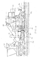
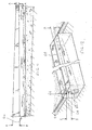
- As for prior art slot drains, referring to
Figures 1 and 2 , they typically have a shortcoming in not having any self-cleaning capability. As a result, dirt, leaves etc. get built up gradually in the drains leading to blockage and hence flooding on the motorways. - It is an object of the present invention to provide a slipforming assembly and method which may ameliorate the above shortcoming or which may at least provide the public with a useful alternative.
- Accordingly, in one aspect, the present invention provides an assembly for slipforming a slot drain with concrete, the assembly including:
- a slipform paver;
- a movable sleeve adapted to fit over a void forming means;
- a first taut tether provided and maintained in an inclined or declined disposition to provide a parallel reference for guiding the sleeve which in use is driven forward by the slipform paver;
- sensing means adapted to receive guidance from the inclined or declined tether for dictating the elevations and dispositions of the sleeve; and
- one or more actuators connected to the sleeve and adapted to be controlled by the sensing means to achieve the dictated elevations and dispositions of the sleeve.
- Preferably, the assembly includes a slipforming mould adapted to be driven forward by the slipform paver.
- In a preferred embodiment, the sleeve includes a cylindrical pipe. Preferably, the pipe is made of metal. More preferably, the pipe has a chamfered end configured to reduce concrete load on the cylindrical pipe during dispensing of the concrete.
- Preferably, the tether includes a stringline held in place by a system of stakes and fastening means.
- In a preferred embodiment, there are first and second actuators, the first actuator being associated with a first end of the pipe, the second actuator being associated with a second end of the pipe. Preferably, the first actuator is adapted to actuate a first connecting means which is affixed to the first end of the pipe. More preferably, the second actuator is adapted to actuate a second connecting means which is affixed to the second end of the pipe. Even more preferably, the first and second connecting means are in the form of plates. Each of the first and second actuators is preferred to be a hydraulic ram. Preferably, the plates, being disposed perpendicular to one another. More preferably, the plates are connected to or form part of the slipforming mould.
- In a preferred embodiment, the sensing means include first and second sensing wands, each adapted to ride beneath the stringline to receive guidance. Preferably, the first and second sensing wands are in electronic communication with a control means. More preferably, the first and second wands are capable of feeding signals to the control means via an amplifier to operate the first and second actuators, respectively. Preferably, the first and second actuators are synchronised to place and maintain the forward moving cylindrical pipe in the inclined or declined disposition at a selected angle. As such, after slipforming, the slot drain ends up with a change of fall or rise from pit to pit.
- In a preferred embodiment, the slipforming mould includes form guiding means adapted to define an upper portion of the slot drain. Preferably, an uppermost surface of the upper portion forms a longitudinally level road surface. More preferably, the form guiding means are in the form of a pair of substantially L-shaped elongate brackets. Conveniently, each of the pair of L-shaped brackets includes first and second limbs. It is preferred that each first limb is transversely slanted so as to form the uppermost surface capable of directing water flows towards the slipformed slot. Preferably, each second limb is substantially vertically placed.
- In a preferred embodiment, the assembly includes means adapted to allow the form guiding means to be adjustably placed at a desired level. The means are preferred to include a pair of longitudinally elongate legs, each leg having a foot. Preferably, each leg is extendably connected to the corresponding second limb of each L-shaped bracket. As such, the form guiding means may be adjusted to a higher level when the leg is moved to an extended position. Preferably, each leg is configured to be inwardly inclined so as to prevent excess concrete from escaping during slipforming. Even more preferably, the foot of each leg is adapted in use to rest on a base alongside the trench.
- Preferably, the assembly includes a pair of activators adapted to allow manual control of each longitudinally elongate leg. More preferably, the activators are provided towards the opposite ends of the longitudinally elongate leg.
- In a preferred embodiment, the assembly includes a second taut tether adapted to be provided and maintained in a level disposition to provide a parallel reference for controlling the steering and elevation of the slipform paver as it moves forward.
- It is preferred that the void forming means is a deflatable tube being sealed at one end. During preparation, the tube with the sealed end is laid in an excavated trench in a deflated state, fed through the sleeve and then inflated.
- Preferably, the slipforming mould is driven by the slipform paver to move forward along a length of the excavated trench.
- In a preferred embodiment, the slipform paver includes an auger and one or more vibrators.
- More preferably, air-entrained concrete is delivered from a truck mixer to the slipforming mould via an auger mounted on the slipform paver. The concrete is preferably filled through the top of a hopper and dispensed through the bottom of the hopper into the slipforming mould.
- Preferably, the auger is in the form of a screw-type device used to transfer the concrete into the slipforming mould. More preferably, each or the vibrator is configured to agitate the concrete so that it properly fills the slipforming mould and to consolidate the agitated concrete.
- According, in another aspect, the present invention provides a method of slipforming a slot drain with concrete, the method including the steps of:
- providing a slipform paver;
- fitting a movable sleeve over a void forming means;
- providing and maintaining a first taut tether in an inclined or declined disposition to provide a parallel reference for guiding the sleeve which in use is driven forward by the slipform paver;
- providing sensing means adapted to receive guidance from the inclined or declined first tether for dictating the elevations and dispositions of the sleeve; and providing one or more actuators connected to the sleeve and adapted to be controlled by the sensing means to achieve the dictated elevations and dispositions of the sleeve.
- Preferably, the method includes the step of moving the slipform paver thereby causing the sleeve to move accordingly at a selected angle of inclination or declination along an excavated trench whilst the concrete is dispensed from a slipforming mould.
- Preferably, the method includes the step of running the slipform paver from pit to pit resulting in the slot drain having a changing fall or rise from pit to pit.
- Preferably, the method is preferred to include the steps of letting the concrete set and then deflating and removing the void forming means.
- The invention may be better understood from the following non-limiting description of a preferred embodiment, in which:
-
Figure 1 is a side elevation of an opened prior art slot drain; -
Figure 2 a cross-sectional view of the prior art slot drain ofFigure 1 ; -
Figure 3 is a front perspective view of a slipforming assembly in accordance with the present invention; -
Figure 4 is a side perspective view of the slipforming assembly ofFigure 3 ; -
Figure 5 is a schematic drawing illustrating the stringlines arrangement in the slipforming assembly ofFigure 1 ; -
Figure 6 is an internal side elevation of selected components of the slipforming assembly ofFigure 1 with the metal pipe being exposed; -
Figure 7 is a front end view of the slipforming assembly ofFigure 1 ; -
Figure 8 is a rear end view of the slipforming assembly ofFigure 1 ; -
Figure 9 is an external side elevation of selected components of the slipforming assembly ofFigure 1 with the metal pipe being concealed; -
Figure 10 is a side elevation of the slipforming assembly ofFigure 1 with the metal pipe exposed within the excavated trench; and -
Figure 11 is a side elevation of an opened and inclined slot drain formed by the slipforming assembly ofFigure 1 ; and -
Figure 12 is a perspective view of the slot drain ofFigure 11 . - Referring to
Figures 3 to 6 , anassembly 10 for slipforming a slot drain with concrete is shown. Theassembly 10 has aslipform paver 12, a movable sleeve, a void forming means and a taut tether. The movable sleeve is in the form of acylindrical metal pipe 14 configured to fit over the void forming means which takes the form of adeflatable tube 16 being sealed at one end. During preparation, thetube 16 with the sealed end is laid in an excavatedtrench 18 in a deflated state, fed through themetal pipe 14 and then inflated. - As best shown in
Figures 4 and5 , theassembly 10 has a first taut tether in the form of astringline 20 being held in place by a system ofstakes 22 and fastening means such as clampingdevices 24 alongside the excavatedtrench 18. The stringline may be made of wire, cable, woven nylon, polyethylene rope, or similar materials. In the present embodiment, thestringline 20 is provided and maintained in an inclined disposition to provide a parallel reference for guiding themetal pipe 14 which in use is driven forward by theslipform paver 12. It should be noted that thestringline 20 may be provided and maintained in a declined disposition as well, depending on the desired ultimate disposition of the slot drain and on the side of the excavatedtrench 18 on which theslipform paver 12 is located. - As shown in
Figures 4 and5 , theassembly 10 also includes sensing means and two actuators. The sensing means are in the form ofwands 25 & 26 designed to receive guidance from theinclined stringline 20 for dictating the elevations and dispositions of themetal pipe 14. The actuators are in the form of hydraulic rams which are connected to themetal pipe 14. The actuators are controlled by thesensing wands 24 to achieve the dictated elevations and dispositions of themetal pipe 14. - Referring to
Figures 6 to 8 , one of the actuators being ahydraulic ram 28 is associated with afirst end 30 of thepipe 14 whereas the other actuator being anotherhydraulic ram 32 is associated with anopposite end 34 of thepipe 14. Thehydraulic ram 28 is connected to a (first) connecting means being in the form of aplate 36. Thehydraulic ram 28 is configured to actuate theplate 36 which is welded to thefirst end 30 of thepipe 14. Thehydraulic ram 32 is also connected to a (second) connecting means which is also in the form of aplate 38. Part of the base ofplate 38 is welded to almost half of the length of thepipe 14 covering theend 34. Thehydraulic ram 32 is connected an upper part of theplate 38 and is capable of actuating thepipe 14 via theplate 38. In the present embodiment, theplates 36 & 38 are disposed perpendicular to one another and form part of aslipforming mould 46. - Turning to
Figures 4 &5 , each of thesensing wands 25 & 26 is adapted to ride beneath thestringline 20 to receive guidance. Both sensingwands 25 & 26 are in electronic communication with a control means in the form of a box 40. Thewands 25 & 26 are capable of feeding signals to the control box 40 via an amplifier, which is built in the control box 40, to operate thehydraulic rams 28 & 32, respectively. It will be appreciated that thehydraulic rams 28 & 32 are synchronised to place and maintain themetal pipe 14 in the inclined disposition at a selected angle as it moves forward as indicated byarrow 42 as shown inFigures 3 to 5 . As such, once slipforming is completed, the slot drain ends up with a change of fall from pit to pit. - As shown in
Figure 6 , themetal pipe 14 has a chamferedend 44 configured to reduce the concrete load on themetal pipe 14 during dispensing of the concrete. - Referring to
Figures 9 and10 , theassembly 10 has aslipforming mould 46 which during operation is driven forward by theslipform paver 12. Theslipforming mould 46 includes form guiding means which are in the form of a pair of substantially L-shapedelongate brackets 48 & 50. Each of the pair of L-shapedbrackets Figure 8 . Each first limb 52, 56 is transversely slanted so as to form the uppermost surface 60 (seeFigure 12 ) of theslot drain 62 capable of directing water flows towards theslipformed slot 64. Each of thesecond limbs 54 & 58 is substantially vertically placed. Theelongate brackets 48 & 50 are provided and configured to define anupper portion 66 of theslot drain 62 to be slipformed. Once theslot drain 62 has been slipformed, the uppermost surface 60 of theupper portion 66 would form a longitudinallylevel road surface 68. - Turning to
Figures 8 to 10 , theassembly 10 also includes means adapted to allow theelongate brackets 48 & 50 to be adjustably placed at a desired level. The means are in the form of a pair of longitudinallyelongate legs 70 & 72. Eachleg foot leg second limb 54. 58 of eachelongate bracket brackets legs Figure 8 , eachleg foot leg Figures 2 and7 ) alongside thetrench 18. Each elongate leg is connected to anactivator 80 & 82, for example. Theactivators 80 & 82 being in the form of hydraulic rams are provided and configured to allow manual control of the respective longitudinallyelongate legs 70 & 72. In the present embodiment, the activators (80 & 82 for example) are provided towards the respective opposite ends of each longitudinallyelongate leg - Referring to
Figures 3 ,4 ,5 and10 , the assembly includes a second taut tether also in the form of a stringline 84. The stringline 84 is provided and maintained in a level disposition to provide a parallel reference for controlling the steering and elevation of theslipform paver 12 as it moves forward. - As shown in
Figures 3 and10 , theslipform paver 12 includes a screw-type auger 88 and a number of vibrators (not visible being located inside the slipforming mould 46). During slipforming, air-entrained concrete is delivered from atruck mixer 90 to theslipforming mould 46 via theauger 88 mounted on theslipform paver 12. The concrete is filled through the top of ahopper 92 and dispensed through the bottom of thehopper 92 into theslipforming mould 46. The vibrators function to agitate the concrete so that it properly fills theslipforming mould 46. The vibrators also consolidate the agitated concrete. - In operation, slipforming a slot drain with concrete using the method of the present invention involves the steps of providing the
slipform paver 12, fitting themetal pipe 14 over a deflatedtube 16, setting and maintaining thestringline 20 in an inclined (or declined if desired) position to provide a parallel reference for guiding themetal pipe 14 which in use is driven forward by theslipform paver 12. During operation, thesensing wands 25 & 26 receive guidance from theinclined stringline 20 thereby dictating the elevations and dispositions of themetal pipe 14 via thehydraulic rams hydraulic rams 28 & 32 in order to achieve the dictated elevations and dispositions of themetal pipe 14. Forward movement of theslipform paver 12 causes themetal pipe 14 to move accordingly at a selected angle of inclination (or declination) along the excavatedtrench 18 whilst the concrete is dispensed from theslipforming mould 46. As shown inFigures 11 & 12 , running theslipform paver 12 from pit to pit results in theslot drain 62 having a changing fall or rise. The last steps are to let the concrete set and then deflate and remove the void forming means. After forming theslot drain 62, a layer of hot mix 94 (seeFigure 12 ) is then poured onto the base 78 such that the upper surface of the hot mix 94 and the uppermost surface 60 of theslot drain 62 are at grade. - It can be seen from
Figures 11 & 12 that the distance between the road surface and the top of the drain at one end of thedrain 62, indicated by arrows A-A, is significantly shorter than that indicated by arrows B-B at an opposite end. As such, theinclined slot drain 62 has the capability of self-cleaning with any dirt, leaves etc. being flushed towards the downstream pit by flowing rain water that naturally runs down the metal pipe 14 (as illustrated by the arrows shown inFigures 11 & 12 ) due to gravity. - Now that a preferred embodiment of the present invention has been described in some detail, it will be apparent to a skilled person in the art that the slipforming assembly of the present invention may offer at least the following advantages:
- 1. it enables slipforming of slot drains that are capable of self-cleaning; and
- 2. it provides a cost effective way of producing low maintenance slot drains. Those skilled in the art will appreciate that the invention described herein is susceptible to variations and modifications other than those specifically described. All such variations and modifications are to be considered within the scope and spirit of the present invention the nature of which is to be determined from the foregoing description.
Claims (19)
- An assembly for slipforming a slot drain with concrete, the assembly including:a slipform paver;a movable sleeve adapted to fit over a void forming means;a taut tether provided and maintained in an inclined or declined disposition to provide a parallel reference for guiding the sleeve which in use is driven forward by the slipform paver;sensing means adapted to receive guidance from the inclined or declined tether for dictating the elevations and dispositions of the sleeve; andone or more actuators connected to the sleeve and adapted to be controlled by the sensing means to achieve the dictated elevations and dispositions of the sleeve.
- The assembly of claim 1, which includes a slipforming mould adapted to be driven forward by the slipform paver.
- The assembly of either claim 1 or 2, wherein the sleeve is a cylindrical pipe with a chamfered end configured to reduce concrete load on the cylindrical pipe during dispensing of the concrete.
- The assembly of any one of the preceding claims, which includes first and second actuators, the first actuator being associated with a first end of the pipe, the second actuator being associated with a second end of the pipe.
- The assembly of claim 4, wherein the first actuator is adapted to actuate a first connecting means which is affixed to the first end of the pipe whereas the second actuator is adapted to actuate a second connecting means which is affixed to the second end of the pipe.
- The assembly of claim 5, wherein the first and second connecting means are in the form of plates being disposed perpendicular to one another, each plate being connected to or form part of the slipforming mould.
- The assembly of any one of the preceding claims, wherein the sensing means include first and second sensing wands, each adapted to ride beneath the tether which is in the form of a stringline to receive guidance, the first and second sensing wands being in electronic communication with a control means.
- The assembly of claim 7, wherein the first and second wands are capable of feeding signals to the control means via an amplifier to operate the first and second actuators, respectively.
- The assembly of any one of claims 4 to 8, wherein the first and second actuators are adapted to be synchronised to place and maintain the forward moving cylindrical pipe in the inclined or declined disposition at a selected angle.
- The assembly of any one of claims 2 to 9, wherein the slipforming mould includes form guiding means adapted to define an upper portion of the slot drain, the uppermost surface of the upper portion forming a longitudinally level road surface.
- The assembly of claim 10, wherein the form guiding means are in the form of a pair of substantially L-shaped elongate brackets, each of the pair of L-shaped brackets including first and second limbs.
- The assembly of claim 11, wherein each first limb is transversely slanted so as to form the uppermost surface capable of directing water flows towards the slipformed slot, whereas each second limb is substantially vertically placed.
- The assembly of any one of claims 10 to 12, which includes means adapted to allow the form guiding means to be adjustably placed at a desired level.
- The assembly of claim 13, wherein the means include a pair of longitudinally elongate legs, each leg having a foot adapted in use to rest on a base alongside the trench, each leg also being extendably connected to the corresponding second limb of each L-shaped bracket.
- The assembly of claim 14, wherein each leg is configured to be inwardly inclined so as to prevent excess concrete from escaping during slipforming.
- The assembly of either claim 14 or 15, which includes a pair of activators adapted to allow manual control of each longitudinally elongate leg.
- A method of slipforming a slot drain with concrete, the method including the steps of:providing a slipform paver;fitting a movable sleeve over a void forming means;providing and maintaining a taut tether in an inclined or declined disposition to provide a parallel reference for guiding the sleeve which in use is driven forward by the slipform paver;providing sensing means adapted to receive guidance from the inclined or declined first tether for dictating the elevations and dispositions of the sleeve; andproviding one or more actuators connected to the sleeve and adapted to be controlled by the sensing means to achieve the dictated elevations and dispositions of the sleeve.
- The method of claim 17, which includes the step of moving the slipform paver thereby causing the sleeve to move accordingly at a selected angle of inclination or declination along an excavated trench whilst the concrete is dispensed from a slipforming mould.
- The method of either claim 17 or 18, which includes the step of running the slipform paver from pit to pit resulting in the slot drain having a changing fall or rise from pit to pit.
Applications Claiming Priority (1)
| Application Number | Priority Date | Filing Date | Title |
|---|---|---|---|
| AU2014202502 | 2014-05-08 |
Publications (1)
| Publication Number | Publication Date |
|---|---|
| EP2947207A1 true EP2947207A1 (en) | 2015-11-25 |
Family
ID=50735872
Family Applications (1)
| Application Number | Title | Priority Date | Filing Date |
|---|---|---|---|
| EP14171897.3A Withdrawn EP2947207A1 (en) | 2014-05-08 | 2014-07-27 | Assembly and method for slipforming a slot drain |
Country Status (4)
| Country | Link |
|---|---|
| US (1) | US9228300B2 (en) |
| EP (1) | EP2947207A1 (en) |
| AU (1) | AU2014203253A1 (en) |
| CA (1) | CA2854849A1 (en) |
Cited By (1)
| Publication number | Priority date | Publication date | Assignee | Title |
|---|---|---|---|---|
| CN111350259A (en) * | 2020-02-18 | 2020-06-30 | 中铁十九局集团第三工程有限公司 | Construction method of assembled slip-form cast-in-situ drainage ditch |
Families Citing this family (6)
| Publication number | Priority date | Publication date | Assignee | Title |
|---|---|---|---|---|
| KR101725922B1 (en) * | 2015-09-11 | 2017-04-13 | 임남균 | Road noise reduction equipment and installation methods |
| US20190309486A1 (en) * | 2018-04-10 | 2019-10-10 | Locke Solutions, Llc | Monolithic slotted drain |
| CN108360343B (en) * | 2018-04-19 | 2023-12-08 | 江苏四明工程机械有限公司 | Flip-side formwork device for slipform paver |
| US11047095B2 (en) * | 2018-12-28 | 2021-06-29 | Wirtgen Gmbh | Variable height offset mold |
| US11421389B2 (en) * | 2018-12-28 | 2022-08-23 | Wirtgen Gmbh | Variable height mold |
| CN109868712B (en) * | 2019-04-04 | 2024-10-29 | 云南铁甲赋能科技有限公司 | Shoulder forming slip form die |
Citations (2)
| Publication number | Priority date | Publication date | Assignee | Title |
|---|---|---|---|---|
| US3749504A (en) * | 1971-04-30 | 1973-07-31 | Power Curbers Inc | Apparatus for forming a continuous curb structure |
| FR2717513A1 (en) * | 1994-03-21 | 1995-09-22 | Arbex Sa | One stage process for making grooved gutters at edges of roads and motorways |
Family Cites Families (15)
| Publication number | Priority date | Publication date | Assignee | Title |
|---|---|---|---|---|
| US3123883A (en) * | 1964-03-10 | Cast-in-place pipe machine | ||
| US2987891A (en) * | 1958-04-11 | 1961-06-13 | Thomas D Copeland Jr | Pipeline padder assembly |
| US3540226A (en) * | 1966-04-15 | 1970-11-17 | Buddy L Sherrod | Method of towing a vessel on a body of water |
| US3779661A (en) | 1971-05-03 | 1973-12-18 | H Godbersen | Machine and method for preparing a surface and for slip forming a concrete structure |
| US3959977A (en) * | 1974-10-21 | 1976-06-01 | Godbersen Harold W | Concrete slip forming apparatus |
| US5938373A (en) * | 1995-07-20 | 1999-08-17 | Scudder; Erik D. | Apparatus for padding a trench including crusher for pulverizing excavated material into grades of material |
| US5911544A (en) * | 1996-09-05 | 1999-06-15 | Mahony; George K. | Soil compactor |
| US5765966A (en) * | 1996-10-01 | 1998-06-16 | White; Thomas B. | Sub-surface trenching and backfill apparatus |
| US6109825A (en) | 1999-05-26 | 2000-08-29 | Power Curbers, Inc. | Paving apparatus with automatic mold positioning control system |
| US20020064427A1 (en) * | 1999-12-01 | 2002-05-30 | Bond Horace Levaughn | Drain field apparatus and method |
| US7186059B2 (en) * | 2003-04-22 | 2007-03-06 | Tommy Barnes | Padding machine and method of use |
| AT7619U1 (en) * | 2004-02-27 | 2005-06-27 | Hilti & Jehle Gmbh | DEVICE FOR PRODUCING FLUSH-FLOORS SURFACED WITH SLOTTED THROUGH OPENINGS FOR SURFACE DRAINAGE OF TRAFFIC SURFACES |
| US20100008718A1 (en) | 2008-07-11 | 2010-01-14 | Howard Cooper | System and method for slip forming concrete slotted drains |
| US8596914B2 (en) * | 2010-10-21 | 2013-12-03 | Thomas Jeffrey Baber | Tile laying and covering apparatus |
| DE102010051972A1 (en) | 2010-11-19 | 2012-05-24 | Wirtgen Gmbh | Slipformer |
-
2014
- 2014-05-29 US US14/274,221 patent/US9228300B2/en not_active Expired - Fee Related
- 2014-06-16 AU AU2014203253A patent/AU2014203253A1/en not_active Abandoned
- 2014-06-19 CA CA2854849A patent/CA2854849A1/en not_active Abandoned
- 2014-07-27 EP EP14171897.3A patent/EP2947207A1/en not_active Withdrawn
Patent Citations (2)
| Publication number | Priority date | Publication date | Assignee | Title |
|---|---|---|---|---|
| US3749504A (en) * | 1971-04-30 | 1973-07-31 | Power Curbers Inc | Apparatus for forming a continuous curb structure |
| FR2717513A1 (en) * | 1994-03-21 | 1995-09-22 | Arbex Sa | One stage process for making grooved gutters at edges of roads and motorways |
Cited By (1)
| Publication number | Priority date | Publication date | Assignee | Title |
|---|---|---|---|---|
| CN111350259A (en) * | 2020-02-18 | 2020-06-30 | 中铁十九局集团第三工程有限公司 | Construction method of assembled slip-form cast-in-situ drainage ditch |
Also Published As
| Publication number | Publication date |
|---|---|
| US20150322633A1 (en) | 2015-11-12 |
| AU2014203253A1 (en) | 2015-11-26 |
| CA2854849A1 (en) | 2015-11-08 |
| US9228300B2 (en) | 2016-01-05 |
Similar Documents
| Publication | Publication Date | Title |
|---|---|---|
| US9228300B2 (en) | Slipforming assembly | |
| AU2004233127B2 (en) | Low surface area shearing device | |
| US8956075B1 (en) | Tunnel mold, system and method for slip forming reinforced concrete structures with exposed rebars | |
| US8920068B1 (en) | Process for slip forming reinforced bridge coping with exposed rebars | |
| JP2010144504A (en) | Paving screed, and method for laying paving mat | |
| WO2018033516A1 (en) | Slope finisher | |
| US3362308A (en) | Concrete gutter and curb forming machine | |
| US6719486B2 (en) | Apparatus for screeding | |
| US3031938A (en) | Variable road widener | |
| US4152382A (en) | Method of slip forming concrete | |
| US5573347A (en) | Drain preparation apparatus and method of using same | |
| CN111608041B (en) | Concrete pavement paving method | |
| JPS62502128A (en) | Pile construction method and equipment for implementing this method | |
| US20100008718A1 (en) | System and method for slip forming concrete slotted drains | |
| CN112482535A (en) | Cast-in-place construction and maintenance method for trapezoid drainage ditch | |
| US3861157A (en) | Apparatus for depositing under water a flowable hardenable or not hardenable mass | |
| DE10358363B4 (en) | Slipform paver for the production of surface coverings | |
| JP6255262B2 (en) | Underground pipe laying device | |
| ITMI20071736A1 (en) | MIXER / DISPENSER IN CONTINUOUS MORTAR FOR FILLING CHANNELS, TRINCEES OR EXCAVATIONS | |
| JP3739767B2 (en) | Placing device and leveling device for mortar used in waterway construction method | |
| US4564314A (en) | Self-propelled continuous concrete pipe-laying machine | |
| EP1067243A2 (en) | Catchment basin for above ground water and construction method thereof | |
| JP3722981B2 (en) | Method of forming a water shielding layer on a slope | |
| US6341919B1 (en) | Threaded side bar inserter | |
| US1750137A (en) | Method of and apparatus for setting precast forms in aqueous bodies |
Legal Events
| Date | Code | Title | Description |
|---|---|---|---|
| PUAI | Public reference made under article 153(3) epc to a published international application that has entered the european phase |
Free format text: ORIGINAL CODE: 0009012 |
|
| AK | Designated contracting states |
Kind code of ref document: A1 Designated state(s): AL AT BE BG CH CY CZ DE DK EE ES FI FR GB GR HR HU IE IS IT LI LT LU LV MC MK MT NL NO PL PT RO RS SE SI SK SM TR |
|
| AX | Request for extension of the european patent |
Extension state: BA ME |
|
| STAA | Information on the status of an ep patent application or granted ep patent |
Free format text: STATUS: THE APPLICATION IS DEEMED TO BE WITHDRAWN |
|
| 18D | Application deemed to be withdrawn |
Effective date: 20160526 |