EP2947027A1 - Dual content mixing container - Google Patents
Dual content mixing container Download PDFInfo
- Publication number
- EP2947027A1 EP2947027A1 EP14740803.3A EP14740803A EP2947027A1 EP 2947027 A1 EP2947027 A1 EP 2947027A1 EP 14740803 A EP14740803 A EP 14740803A EP 2947027 A1 EP2947027 A1 EP 2947027A1
- Authority
- EP
- European Patent Office
- Prior art keywords
- rotation
- cap
- mixing container
- protrusion
- circumferential surface
- Prior art date
- Legal status (The legal status is an assumption and is not a legal conclusion. Google has not performed a legal analysis and makes no representation as to the accuracy of the status listed.)
- Withdrawn
Links
Images



Classifications
-
- B—PERFORMING OPERATIONS; TRANSPORTING
- B65—CONVEYING; PACKING; STORING; HANDLING THIN OR FILAMENTARY MATERIAL
- B65D—CONTAINERS FOR STORAGE OR TRANSPORT OF ARTICLES OR MATERIALS, e.g. BAGS, BARRELS, BOTTLES, BOXES, CANS, CARTONS, CRATES, DRUMS, JARS, TANKS, HOPPERS, FORWARDING CONTAINERS; ACCESSORIES, CLOSURES, OR FITTINGS THEREFOR; PACKAGING ELEMENTS; PACKAGES
- B65D81/00—Containers, packaging elements, or packages, for contents presenting particular transport or storage problems, or adapted to be used for non-packaging purposes after removal of contents
- B65D81/32—Containers, packaging elements, or packages, for contents presenting particular transport or storage problems, or adapted to be used for non-packaging purposes after removal of contents for packaging two or more different materials which must be maintained separate prior to use in admixture
-
- A—HUMAN NECESSITIES
- A47—FURNITURE; DOMESTIC ARTICLES OR APPLIANCES; COFFEE MILLS; SPICE MILLS; SUCTION CLEANERS IN GENERAL
- A47J—KITCHEN EQUIPMENT; COFFEE MILLS; SPICE MILLS; APPARATUS FOR MAKING BEVERAGES
- A47J43/00—Implements for preparing or holding food, not provided for in other groups of this subclass
- A47J43/27—Implements for preparing or holding food, not provided for in other groups of this subclass for mixing drinks; Hand-held shakers
-
- B—PERFORMING OPERATIONS; TRANSPORTING
- B05—SPRAYING OR ATOMISING IN GENERAL; APPLYING FLUENT MATERIALS TO SURFACES, IN GENERAL
- B05B—SPRAYING APPARATUS; ATOMISING APPARATUS; NOZZLES
- B05B11/00—Single-unit hand-held apparatus in which flow of contents is produced by the muscular force of the operator at the moment of use
- B05B11/0005—Components or details
- B05B11/0078—Arrangements for separately storing several components
- B05B11/0081—Arrangements for separately storing several components and for mixing the components in a common container as a mixture ready for use before discharging the latter
-
- B—PERFORMING OPERATIONS; TRANSPORTING
- B65—CONVEYING; PACKING; STORING; HANDLING THIN OR FILAMENTARY MATERIAL
- B65D—CONTAINERS FOR STORAGE OR TRANSPORT OF ARTICLES OR MATERIALS, e.g. BAGS, BARRELS, BOTTLES, BOXES, CANS, CARTONS, CRATES, DRUMS, JARS, TANKS, HOPPERS, FORWARDING CONTAINERS; ACCESSORIES, CLOSURES, OR FITTINGS THEREFOR; PACKAGING ELEMENTS; PACKAGES
- B65D47/00—Closures with filling and discharging, or with discharging, devices
-
- B—PERFORMING OPERATIONS; TRANSPORTING
- B65—CONVEYING; PACKING; STORING; HANDLING THIN OR FILAMENTARY MATERIAL
- B65D—CONTAINERS FOR STORAGE OR TRANSPORT OF ARTICLES OR MATERIALS, e.g. BAGS, BARRELS, BOTTLES, BOXES, CANS, CARTONS, CRATES, DRUMS, JARS, TANKS, HOPPERS, FORWARDING CONTAINERS; ACCESSORIES, CLOSURES, OR FITTINGS THEREFOR; PACKAGING ELEMENTS; PACKAGES
- B65D51/00—Closures not otherwise provided for
- B65D51/24—Closures not otherwise provided for combined or co-operating with auxiliary devices for non-closing purposes
- B65D51/28—Closures not otherwise provided for combined or co-operating with auxiliary devices for non-closing purposes with auxiliary containers for additional articles or materials
-
- B—PERFORMING OPERATIONS; TRANSPORTING
- B65—CONVEYING; PACKING; STORING; HANDLING THIN OR FILAMENTARY MATERIAL
- B65D—CONTAINERS FOR STORAGE OR TRANSPORT OF ARTICLES OR MATERIALS, e.g. BAGS, BARRELS, BOTTLES, BOXES, CANS, CARTONS, CRATES, DRUMS, JARS, TANKS, HOPPERS, FORWARDING CONTAINERS; ACCESSORIES, CLOSURES, OR FITTINGS THEREFOR; PACKAGING ELEMENTS; PACKAGES
- B65D83/00—Containers or packages with special means for dispensing contents
-
- B—PERFORMING OPERATIONS; TRANSPORTING
- B05—SPRAYING OR ATOMISING IN GENERAL; APPLYING FLUENT MATERIALS TO SURFACES, IN GENERAL
- B05B—SPRAYING APPARATUS; ATOMISING APPARATUS; NOZZLES
- B05B11/00—Single-unit hand-held apparatus in which flow of contents is produced by the muscular force of the operator at the moment of use
- B05B11/01—Single-unit hand-held apparatus in which flow of contents is produced by the muscular force of the operator at the moment of use characterised by the means producing the flow
- B05B11/02—Membranes or pistons acting on the contents inside the container, e.g. follower pistons
- B05B11/028—Pistons separating the content remaining in the container from the atmospheric air to compensate underpressure inside the container
-
- B—PERFORMING OPERATIONS; TRANSPORTING
- B05—SPRAYING OR ATOMISING IN GENERAL; APPLYING FLUENT MATERIALS TO SURFACES, IN GENERAL
- B05B—SPRAYING APPARATUS; ATOMISING APPARATUS; NOZZLES
- B05B11/00—Single-unit hand-held apparatus in which flow of contents is produced by the muscular force of the operator at the moment of use
- B05B11/01—Single-unit hand-held apparatus in which flow of contents is produced by the muscular force of the operator at the moment of use characterised by the means producing the flow
- B05B11/10—Pump arrangements for transferring the contents from the container to a pump chamber by a sucking effect and forcing the contents out through the dispensing nozzle
- B05B11/1001—Piston pumps
- B05B11/1023—Piston pumps having an outlet valve opened by deformation or displacement of the piston relative to its actuating stem
-
- B—PERFORMING OPERATIONS; TRANSPORTING
- B05—SPRAYING OR ATOMISING IN GENERAL; APPLYING FLUENT MATERIALS TO SURFACES, IN GENERAL
- B05B—SPRAYING APPARATUS; ATOMISING APPARATUS; NOZZLES
- B05B11/00—Single-unit hand-held apparatus in which flow of contents is produced by the muscular force of the operator at the moment of use
- B05B11/01—Single-unit hand-held apparatus in which flow of contents is produced by the muscular force of the operator at the moment of use characterised by the means producing the flow
- B05B11/10—Pump arrangements for transferring the contents from the container to a pump chamber by a sucking effect and forcing the contents out through the dispensing nozzle
- B05B11/1042—Components or details
- B05B11/1043—Sealing or attachment arrangements between pump and container
- B05B11/1046—Sealing or attachment arrangements between pump and container the pump chamber being arranged substantially coaxially to the neck of the container
- B05B11/1047—Sealing or attachment arrangements between pump and container the pump chamber being arranged substantially coaxially to the neck of the container the pump being preassembled as an independent unit before being mounted on the container
-
- B—PERFORMING OPERATIONS; TRANSPORTING
- B05—SPRAYING OR ATOMISING IN GENERAL; APPLYING FLUENT MATERIALS TO SURFACES, IN GENERAL
- B05B—SPRAYING APPARATUS; ATOMISING APPARATUS; NOZZLES
- B05B11/00—Single-unit hand-held apparatus in which flow of contents is produced by the muscular force of the operator at the moment of use
- B05B11/01—Single-unit hand-held apparatus in which flow of contents is produced by the muscular force of the operator at the moment of use characterised by the means producing the flow
- B05B11/10—Pump arrangements for transferring the contents from the container to a pump chamber by a sucking effect and forcing the contents out through the dispensing nozzle
- B05B11/1042—Components or details
- B05B11/1066—Pump inlet valves
- B05B11/1067—Pump inlet valves actuated by pressure
- B05B11/1069—Pump inlet valves actuated by pressure the valve being made of a resiliently deformable material or being urged in a closed position by a spring
-
- B—PERFORMING OPERATIONS; TRANSPORTING
- B05—SPRAYING OR ATOMISING IN GENERAL; APPLYING FLUENT MATERIALS TO SURFACES, IN GENERAL
- B05B—SPRAYING APPARATUS; ATOMISING APPARATUS; NOZZLES
- B05B11/00—Single-unit hand-held apparatus in which flow of contents is produced by the muscular force of the operator at the moment of use
- B05B11/01—Single-unit hand-held apparatus in which flow of contents is produced by the muscular force of the operator at the moment of use characterised by the means producing the flow
- B05B11/10—Pump arrangements for transferring the contents from the container to a pump chamber by a sucking effect and forcing the contents out through the dispensing nozzle
- B05B11/1042—Components or details
- B05B11/1073—Springs
- B05B11/1074—Springs located outside pump chambers
Definitions
- the present invention relates to a dual content mixing container, and the dual content mixing container according to the present invention is constituted in such a way that a second content substance housed in a storage chamber is mixed with a first content substance housed in a main container body by moving a hermetically sealing member downwards by means of action whereby a rotating cap is rotated, and thus the invention affords convenience to the user as the first and second content substances can be mixed by means of a simple action.
- a container used or in circulation is mostly made to keep contents of one kind in one container to be used.
- a mixing container for different contents comprising a housing having a storing compartment storing contents, a piston being installed in the interior of the storing compartment; a guide bracket which is engaged to the top of the housing, an engaging shoulder protruding toward the inner side of the storing compartment, a guide piece formed at the top of the guide bracket and extending upward; a button part operating as it is inserted in the guide piece and having a pumping member for the contents to discharge through a discharge port by a user's work; a sealing ring which is installed to selectively part between the guide bracket and the button part; and a storing container comprising a receiver member which is installed at the button part and contains contents which is different from the contents stored in the storing compartment, the lower side of the receiver member being supported by the engaging shoulder; and a sealing member which selectively seals the lower side of the receiver member and is engaged to the lower side of the pumping member and has a communication hole allowing the pumping member and the storing compartment to communicate during the pumping of the pump
- the above registered patent has a composition, wherein a sealing member moves downwards by a pumping member when a button member is pressed downwards after a sealing seal is removed, and thereby opens lower end of a receiver member; as a result, contents kept inside of the receiving member flows into a storing compartment, leading to mixing two-type materials.
- the above registered patent has a problem wherein the residue remaining in the sealing ring when the sealing ring is removed, which does not look good in external appearance. Also, only when a button part is pressed downwards after the sealing ring is removed, a sealing member moves downwards and makes two-type materials mixed, which leads to user inconvenience.
- the present invention is devised to solve the said problems above, and its goal is to provide dual content mixing container, which has a composition wherein a sealing member moves downwards by the operation of rotating a rotation cap and second contents kept in a storage chamber mixes with a first content substance kept in a main container body, so that by a simple manipulation it is possible for two-type contents to be mixed, leading to user convenience.
- dual content mixing container comprises a main container body in which a first content substance is kept; an inner cap which is combined as encircling a upper part of the main container body, wherein a which forms space for storing second contents is equipped, and wherein a pair of sloped portions corresponding each other is formed as encircling the inner circumferential surface; a rotation cap which is coupled to be able to rotate as encircling the inner cap on upper portion of the main container body; a sealing member which closes an end of a storage chamber of the main container body, and descends by rotation of the rotation cap; a pump support body which is formed to be interlocked inside the rotation cap and rotated with rotation of the rotation cap, comprising a pump combining tube where a pumping member is coupled and a securing plate which is coupled as encircling the pump combining tube and is secured on the inner cap; a pressurizing member combined to upper portion of the sealing member is rotated being interlocked with the pump support body, wherein with
- a coupling groove is equipped on an outer circumferential surface of the pump support body in order for the rotation cap to be interlocked, and that a coupling protrusion combined to the coupling groove is equipped on an inner circumferential surface of the rotation cap.
- a pair of rotation limiting protrusions corresponding each other are equipped on an outer circumferential surface to limit the range of rotation of the rotation cap, and that rotation limiting protrusions which move inside of the rotation limiting protrusion are equipped on an inner circumferential surface.
- a reverse rotation preventing protrusion is equipped in order to prevent the rotation cap from being rotated into the other direction.
- the reverse rotation preventing protrusion forms a gentle slope on one side and forms a vertical slope on the other side.
- a vertical guide groove is equipped longitudinally on both sides of an inner circumferential surface of the pressurizing member, and on both sides of an outer circumferential surface of the pump combining tube is equipped a vertical guide protrusion which is coupled to the vertical guide groove and guides a vertical movement of the pressurizing member.
- the present invention has an advantage in that a sealing member moves downward with the rotating operation of a rotation cap, and second contents kept in a storage chamber mixes with a kept in a main container body, so that by simple manipulation, it is possible to make the first and the second contents mixed, and thereby to provide a user with user convenience.
- FIG.1 is an exploded perspective view illustrating a configuration of a dual content mixing container according to an exemplary embodiment of the present invention.
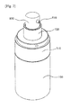
- FIG.2 is an assembled perspective view illustrating a configuration of a dual content mixing container according to an exemplary embodiment of the present invention.
- FIG.3 is cross-sectional views illustrating a configuration of a dual content mixing container according to an exemplary embodiment of the present invention.
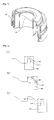
- Figs.4 is an explanatory view illustrating a combination of a pump support body and a pressurizing member of a dual content mixing container according to an exemplary embodiment of the present invention.
- Fig.5 is an explanatory view illustrating a configuration of a sloped portion of an inner cap of a dual content mixing container according to an exemplary embodiment of the present invention.
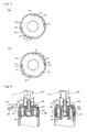
- Fig.6 is an explanatory view illustrating a configuration wherein a descending guide protrusion of a pressurizing member of a dual content mixing container descends along a sloped portion of an inner cap according to an exemplary embodiment of the present invention.
- Fig.7 is an explanatory view illustrating a configuration wherein a rotation limiting groove of a rotation cap of a dual content mixing container moves inside a rotation limiting groove of an inner cap according to an exemplary embodiment of the present invention.
- a dual content mixing container includes a main container body 100, an inner cap 200, a rotation cap 300, a sealing member 400, a pump support body 500, a pressurizing member 600, a pumping member 700, and a button member 800.
- the main container body 100 keeps a first content substance and in the main container body comprises a piston 110 which ascends according to use of contents.
- the inner 200 encircling and combined to the main container body 100, forms a hollow so that a pump combining tube 510 of the pump support body 500 can be combined.
- a storage chamber210 which forms a space where second contents, either powder or liquid, is kept, wherein the storage chamber210 has an open end for the second contents to be filled, and after the second contents is filled, the open end is configured to be closed by the sealing member 600, so as to prevent the second contents filled in the storage chamber210 from flowing back into the main container body 100.
- the second contents stored in the storage chamber210 when the sealing member 600 descends and thereby the open end of the storage chamber210 is separated from the sealing member 600, drop into the main container body 100 and mixes with the first content substance.
- a pair of sloped portions corresponding to each other are formed protrusively, encircling an inner circumferential surface, wherein the lower end of the sloped portion 220 pressurizes a descending guide protrusion 610 of a pressurizing 600 and guides the pressurizing member 600 to move downwards.
- a pair of a rotation limiting grooves 230 opposing to each other in order to limit the rotation range of a rotation cap 300, wherein on a fore-end of the rotation limiting grooves 230 is formed a latching protrusion 231.
- a reverse rotation preventing protrusion 232 has a gentle slope on one side so that a rotation limiting protrusion 312 can slide over, whereas the other side has a vertical surface so that a reverse rotation preventing protrusion 312 cannot slide over.
- the rotation cap 300 which, encircling the inner cap 200, is combined to be rotated on a upper portion of the main container body 100, comprises a body 310 which a user can grip with a hand in the middle to rotate the rotation cap 300 and a button insertion part 320 which is extended from a upper central part of the body 310 to the upward direction for a button member 800 to be inserted.
- a coupling protrusion 311, which is coupled to a coupling groove 521 of the pump support body 500, is formed on an inner circumferential surface so that when the rotation cap 300 rotates, a pump support 500 rotates together.
- a rotation limiting protrusion 312 moving inside a rotation limiting groove 230 is formed, wherein the rotation limiting protrusion 312, as shown in Fig. 7 , is placed, being supported by a latching protrusion 231 located on an end of the rotation limiting groove 230, and moves along the rotation limiting groove 230, thereby supported by a reverse rotation preventing protrusion 232.
- the rotation limiting protrusion 312 is formed opposing to the other side of the vertical surface of the reverse rotation preventing protrusion 232, in order to prevent reverse rotation of the rotation cap 300 in a state of being supported to the reverse rotation preventing protrusion 232.
- a rotation display part displaying a rotating direction is formed on an outer circumferential surface of the body 310.
- an outer cap 900 is combined on upper portion of the rotation cap 300 so as to prevent a button member 800 from malfunctioning and to block foreign substances inflowing.
- the sealing member 400 closes an opened lower end of the storage chamber210, comprising a sealing tube 410 which closes an end of an inner circumferential surface of the storage chamber210 and a sealing tube 410 which is extended to upper direction on most of central area of the sealing tube 410 and combined with fit with the pressuring member 600.
- the sealing member 400 is composed to descend by pressurization of a pressurizing member 600 which descends by rotation of the inner cap 200 when the rotation cap 300 rotates, wherein, when the pressurizing member 600 descends, the sealing member 400 is pressurized by a protrusion 630 of the pressurizing member 600 and descends; hence, a sealing tube 410 is separated from an opened lower end of the storage chamber210, so that second contents kept in a storage chamber210 free-falls, thereby enabling a first content substance and second contents to be mixed.
- the pump support body 500 is composed to be interlocked inside of the rotation cap 300 with an inner surface of the rotation cap 300, and rotates according to rotation of the rotation cap 300, comprising a pump combining tube 510 to which a pumping member 700 is combined and a securing plate 520 which, encircling the pump combining tube 510, is secured on a upper portion of the inner cap 200.
- a coupling groove 521 with a coupling protrusion 311 of the rotation cap 300 coupled, is equipped on an outer circumferential surface of the pump support body 500, and is composed to be rotated along with rotation of the rotation cap 300 while interlocked with the rotation cap 300 through combination with the coupling protrusion 311.
- a vertical guide protrusion 511 which is combined with the vertical guide groove 620 of the pressurizing member 600 and guides vertical movements of the pressurizing member 600.
- the pressurizing member 600 is combined with upper portion of the sealing member 400, descends by rotation of the rotation cap 300, and moves the sealing member 400 to downward direction; regarding to the present invention, it is featured that on both sides of the pressurizing member 600 are equipped a pair of descending guide protrusions 610 which respectively meet lower ends of a pair of sloped portions 220.
- the descending guide protrusion 610 when the pressurizing member 600 rotates, is composed to move downwards along the lower end surface of the sloped portion 220, and then moves from a top dead center to a bottom dead center of the sloped portion 220 by rotation, thereby guiding the pressurizing member 600 to move to downward direction.
- the pressurizing member 600 comprises a vertical guide groove 620 to which a vertical guide protrusion 511 is coupled longitudinally on both sides of inner circumferential surfaces in order to interlock with the pump support body 500.
- the pump member 700 is combined with a pumping combining tube 510 of the pump support body 500 and discharges contents by pumping operation in accordance with pressurization of the button member 800.
- the pumping member 700 is a disclosed art; therefore, detailed explanation will be omitted.
- the button member 800 is combined to upper portion of the pumping member 700 and operates the pumping member 700, wherein a discharging hole 810 is equipped on one side surface to be able to discharge contents which moves to upper portion through pumping action of the pumping member 700.
- a descending guide protrusion 610 of the pressurizing member 600 rotates, when the descending guide protrusion 610 moves along a lower end of a sloped portion of an inner cap and moves from a top dead center to a bottom dead center; thereby, the pressurizing member 600 rotate together.
- a protrusion 630 of the pressurizing member 600 pressurizes upper portion of a combining tube 420 and thereby causes a sealing member 400 to descend; as a result, a sealing tube 410 which closes an open end of a storage chamber210 is separated from lower end of the storage chamber210 and opens a lower end of the storage chamber210, thereby leading second contents kept in the storage chamber210 to drop into the main container body 100 and to be mixed with a first content substance.
Landscapes
- Engineering & Computer Science (AREA)
- Mechanical Engineering (AREA)
- Food Science & Technology (AREA)
- Package Specialized In Special Use (AREA)
- Closures For Containers (AREA)
Abstract
Description
- The present invention relates to a dual content mixing container, and the dual content mixing container according to the present invention is constituted in such a way that a second content substance housed in a storage chamber is mixed with a first content substance housed in a main container body by moving a hermetically sealing member downwards by means of action whereby a rotating cap is rotated, and thus the invention affords convenience to the user as the first and second content substances can be mixed by means of a simple action.
- Generally, a container used or in circulation is mostly made to keep contents of one kind in one container to be used.
- Recently, in order to improve property of contents, there have been some cases where powdered material is mixed into fluid contents or two-types of contents are mixed and used. In these cases, since additional containers are needed to keep two types of contents, a user should carry and handle two containers to use these contents, thereby leading to inconvenience.
- Additionally, by manufacturing different containers and packaging different contents into separate containers, not only may problems such as a waste of resources be caused. A chemical change such as taste quality change or spoilage may also be caused because a user have no choice but to mix beverages arbitrarily not putatively, thereby resulting in incomplete mixing, as may be a physical change like incomplete dissolution of efficacy when mixing medicines and chemical materials.
- To solve such problems described in the above, various kinds of containers, wherein two-type contents are kept into one container separately and then used by mixing the two-type contents, are being developed.
- Hereinafter, Korean Patent Registration No.
10-1192603 - The above registered patent is provided a mixing container for different contents, comprising a housing having a storing compartment storing contents, a piston being installed in the interior of the storing compartment; a guide bracket which is engaged to the top of the housing, an engaging shoulder protruding toward the inner side of the storing compartment, a guide piece formed at the top of the guide bracket and extending upward; a button part operating as it is inserted in the guide piece and having a pumping member for the contents to discharge through a discharge port by a user's work; a sealing ring which is installed to selectively part between the guide bracket and the button part; and a storing container comprising a receiver member which is installed at the button part and contains contents which is different from the contents stored in the storing compartment, the lower side of the receiver member being supported by the engaging shoulder; and a sealing member which selectively seals the lower side of the receiver member and is engaged to the lower side of the pumping member and has a communication hole allowing the pumping member and the storing compartment to communicate during the pumping of the pumping member.
- The above registered patent has a composition, wherein a sealing member moves downwards by a pumping member when a button member is pressed downwards after a sealing seal is removed, and thereby opens lower end of a receiver member; as a result, contents kept inside of the receiving member flows into a storing compartment, leading to mixing two-type materials.
- However, the above registered patent has a problem wherein the residue remaining in the sealing ring when the sealing ring is removed, which does not look good in external appearance. Also, only when a button part is pressed downwards after the sealing ring is removed, a sealing member moves downwards and makes two-type materials mixed, which leads to user inconvenience.
- The present invention is devised to solve the said problems above, and its goal is to provide dual content mixing container, which has a composition wherein a sealing member moves downwards by the operation of rotating a rotation cap and second contents kept in a storage chamber mixes with a first content substance kept in a main container body, so that by a simple manipulation it is possible for two-type contents to be mixed, leading to user convenience.
- To solve the above problems, dual content mixing container according to the present invention comprises a main container body in which a first content substance is kept; an inner cap which is combined as encircling a upper part of the main container body, wherein a which forms space for storing second contents is equipped, and wherein a pair of sloped portions corresponding each other is formed as encircling the inner circumferential surface; a rotation cap which is coupled to be able to rotate as encircling the inner cap on upper portion of the main container body; a sealing member which closes an end of a storage chamber of the main container body, and descends by rotation of the rotation cap; a pump support body which is formed to be interlocked inside the rotation cap and rotated with rotation of the rotation cap, comprising a pump combining tube where a pumping member is coupled and a securing plate which is coupled as encircling the pump combining tube and is secured on the inner cap; a pressurizing member combined to upper portion of the sealing member is rotated being interlocked with the pump support body, wherein with a pair of descending guide protrusions equipped on upper portion of the pair of sloped portions, the pressurizing member moves along the sloped portions by rotation, lowering the sealing member; a pumping member which is coupled to the pump support body and discharges contents by pumping operation; and a button member which is coupled to upper portion of the pumping member and makes the pumping member operate, wherein a discharging hole is formed for contents to be discharged.
- Furthermore, it is featured that a coupling groove is equipped on an outer circumferential surface of the pump support body in order for the rotation cap to be interlocked, and that a coupling protrusion combined to the coupling groove is equipped on an inner circumferential surface of the rotation cap.
- Furthermore, it is featured that a pair of rotation limiting protrusions corresponding each other are equipped on an outer circumferential surface to limit the range of rotation of the rotation cap, and that rotation limiting protrusions which move inside of the rotation limiting protrusion are equipped on an inner circumferential surface.
- Furthermore, it is featured that on the rotation limiting groove a reverse rotation preventing protrusion is equipped in order to prevent the rotation cap from being rotated into the other direction.
- Furthermore, it is featured that the reverse rotation preventing protrusion forms a gentle slope on one side and forms a vertical slope on the other side.
- Furthermore, it is featured that a vertical guide groove is equipped longitudinally on both sides of an inner circumferential surface of the pressurizing member, and on both sides of an outer circumferential surface of the pump combining tube is equipped a vertical guide protrusion which is coupled to the vertical guide groove and guides a vertical movement of the pressurizing member.
- According to the present invention as described on the above, the present invention has an advantage in that a sealing member moves downward with the rotating operation of a rotation cap, and second contents kept in a storage chamber mixes with a kept in a main container body, so that by simple manipulation, it is possible to make the first and the second contents mixed, and thereby to provide a user with user convenience.
-
-
Fig.1 is a exploded perspective view illustrating a configuration of dual content mixing container according to an exemplary embodiment of the present invention; -
Fig.2 is an assembled perspective view illustrating a configuration of dual content mixing container according to an exemplary embodiment of the present invention. -
Fig.3 is cross-sectional views illustrating a configuration of dual content mixing container according to an exemplary embodiment of the present invention. -
Fig.4 is an explanatory view illustrating a combination of a pump support body and a pressurizing member of a dual content mixing container according to an exemplary embodiment of the present invention. -
Fig.5 is an explanatory view illustrating a configuration of a sloped portion of an inner cap of a dual content mixing container according to an exemplary embodiment of the present invention. -
Fig.6 is an explanatory view illustrating a configuration wherein a descending guide protrusion of a pressurizing member of a dual content mixing container descends along the sloped portion of the inner cap according to an exemplary embodiment of the present invention. -
Fig.7 is an explanatory view illustrating a configuration wherein a rotation limiting groove of a rotation cap of a dual content mixing container moves inside a rotation limiting groove of an inner cap according to an exemplary embodiment of the present invention. -
Fig.8 andFig.9 are explanatory views illustrating a mixing process of first and second contents in a dual content mixing container according to an exemplary embodiment of the present invention - Hereinafter, exemplary embodiments of the present invention will be described in detail with reference to the accompanying drawings. The same reference numerals provided in the drawings indicate the same members.
-
FIG.1 is an exploded perspective view illustrating a configuration of a dual content mixing container according to an exemplary embodiment of the present invention.FIG.2 is an assembled perspective view illustrating a configuration of a dual content mixing container according to an exemplary embodiment of the present invention.FIG.3 is cross-sectional views illustrating a configuration of a dual content mixing container according to an exemplary embodiment of the present invention. -
Figs.4 is an explanatory view illustrating a combination of a pump support body and a pressurizing member of a dual content mixing container according to an exemplary embodiment of the present invention.Fig.5 is an explanatory view illustrating a configuration of a sloped portion of an inner cap of a dual content mixing container according to an exemplary embodiment of the present invention. -
Fig.6 is an explanatory view illustrating a configuration wherein a descending guide protrusion of a pressurizing member of a dual content mixing container descends along a sloped portion of an inner cap according to an exemplary embodiment of the present invention.Fig.7 is an explanatory view illustrating a configuration wherein a rotation limiting groove of a rotation cap of a dual content mixing container moves inside a rotation limiting groove of an inner cap according to an exemplary embodiment of the present invention. - Referring to
Figs.1 to 7 , a dual content mixing container according to an exemplary embodiment of the present invention includes amain container body 100, aninner cap 200, arotation cap 300, asealing member 400, apump support body 500, a pressurizingmember 600, apumping member 700, and abutton member 800. - The
main container body 100 keeps a first content substance and in the main container body comprises apiston 110 which ascends according to use of contents. - The inner 200, encircling and combined to the
main container body 100, forms a hollow so that apump combining tube 510 of thepump support body 500 can be combined. - Regarding to the present invention, inside the
inner cap 200 is equipped a storage chamber210 which forms a space where second contents, either powder or liquid, is kept, wherein the storage chamber210 has an open end for the second contents to be filled, and after the second contents is filled, the open end is configured to be closed by the sealingmember 600, so as to prevent the second contents filled in the storage chamber210 from flowing back into themain container body 100. - The second contents stored in the storage chamber210, when the
sealing member 600 descends and thereby the open end of the storage chamber210 is separated from the sealingmember 600, drop into themain container body 100 and mixes with the first content substance. - Meanwhile, it is featured that a pair of sloped portions corresponding to each other are formed protrusively, encircling an inner circumferential surface, wherein the lower end of the sloped
portion 220 pressurizes a descendingguide protrusion 610 of a pressurizing 600 and guides the pressurizingmember 600 to move downwards. - Meanwhile, on an outer circumferential surface of the
inner cap 200 are formed a pair of arotation limiting grooves 230 opposing to each other, in order to limit the rotation range of arotation cap 300, wherein on a fore-end of therotation limiting grooves 230 is formed alatching protrusion 231. - It is preferred that a reverse
rotation preventing protrusion 232 has a gentle slope on one side so that arotation limiting protrusion 312 can slide over, whereas the other side has a vertical surface so that a reverserotation preventing protrusion 312 cannot slide over. - The
rotation cap 300 which, encircling theinner cap 200, is combined to be rotated on a upper portion of themain container body 100, comprises abody 310 which a user can grip with a hand in the middle to rotate therotation cap 300 and abutton insertion part 320 which is extended from a upper central part of thebody 310 to the upward direction for abutton member 800 to be inserted. - It is preferred that a
coupling protrusion 311, which is coupled to acoupling groove 521 of thepump support body 500, is formed on an inner circumferential surface so that when therotation cap 300 rotates, apump support 500 rotates together. - Regarding to the present invention, it is featured that on an inner circumferential of the
body 310, arotation limiting protrusion 312 moving inside arotation limiting groove 230 is formed, wherein therotation limiting protrusion 312, as shown inFig. 7 , is placed, being supported by alatching protrusion 231 located on an end of therotation limiting groove 230, and moves along therotation limiting groove 230, thereby supported by a reverserotation preventing protrusion 232. - It is preferred that the
rotation limiting protrusion 312 is formed opposing to the other side of the vertical surface of the reverserotation preventing protrusion 232, in order to prevent reverse rotation of therotation cap 300 in a state of being supported to the reverserotation preventing protrusion 232. - Meanwhile, it is preferred that a rotation display part displaying a rotating direction is formed on an outer circumferential surface of the
body 310. - Meanwhile, it is preferred that an
outer cap 900 is combined on upper portion of therotation cap 300 so as to prevent abutton member 800 from malfunctioning and to block foreign substances inflowing. - The sealing
member 400 closes an opened lower end of the storage chamber210, comprising asealing tube 410 which closes an end of an inner circumferential surface of the storage chamber210 and asealing tube 410 which is extended to upper direction on most of central area of thesealing tube 410 and combined with fit with the pressuringmember 600. - Regarding to the present invention, it is featured that the sealing
member 400 is composed to descend by pressurization of a pressurizingmember 600 which descends by rotation of theinner cap 200 when therotation cap 300 rotates, wherein, when the pressurizingmember 600 descends, thesealing member 400 is pressurized by aprotrusion 630 of the pressurizingmember 600 and descends; hence, asealing tube 410 is separated from an opened lower end of the storage chamber210, so that second contents kept in a storage chamber210 free-falls, thereby enabling a first content substance and second contents to be mixed. - The
pump support body 500 is composed to be interlocked inside of therotation cap 300 with an inner surface of therotation cap 300, and rotates according to rotation of therotation cap 300, comprising apump combining tube 510 to which apumping member 700 is combined and asecuring plate 520 which, encircling thepump combining tube 510, is secured on a upper portion of theinner cap 200. - Regarding to the present invention, a
coupling groove 521, with acoupling protrusion 311 of therotation cap 300 coupled, is equipped on an outer circumferential surface of thepump support body 500, and is composed to be rotated along with rotation of therotation cap 300 while interlocked with therotation cap 300 through combination with thecoupling protrusion 311. - Meanwhile, on both sides of an outer circumferential surfaces of the
pump combining tube 510 is equipped avertical guide protrusion 511 which is combined with thevertical guide groove 620 of the pressurizingmember 600 and guides vertical movements of the pressurizingmember 600. - The pressurizing
member 600 is combined with upper portion of the sealingmember 400, descends by rotation of therotation cap 300, and moves the sealingmember 400 to downward direction; regarding to the present invention, it is featured that on both sides of the pressurizingmember 600 are equipped a pair of descendingguide protrusions 610 which respectively meet lower ends of a pair of slopedportions 220. - The descending
guide protrusion 610, shown inFig. 6 , when the pressurizingmember 600 rotates, is composed to move downwards along the lower end surface of the slopedportion 220, and then moves from a top dead center to a bottom dead center of the slopedportion 220 by rotation, thereby guiding the pressurizingmember 600 to move to downward direction. - Meanwhile, the pressurizing
member 600 comprises avertical guide groove 620 to which avertical guide protrusion 511 is coupled longitudinally on both sides of inner circumferential surfaces in order to interlock with thepump support body 500. - The
pump member 700 is combined with apumping combining tube 510 of thepump support body 500 and discharges contents by pumping operation in accordance with pressurization of thebutton member 800. Regarding to the present invention, the pumpingmember 700 is a disclosed art; therefore, detailed explanation will be omitted. - The
button member 800 is combined to upper portion of the pumpingmember 700 and operates the pumpingmember 700, wherein a discharginghole 810 is equipped on one side surface to be able to discharge contents which moves to upper portion through pumping action of the pumpingmember 700. - Hereinafter, mixing procedure of first and second contents by operation of a dual content mixing container according to exemplary embodiment of the present invention will be described in detail.
- First, when a
rotation cap 300 is rotated to one side direction in a state wherein a user grips abody 310 of arotation cap 300, rotation of apump support body 500 interlocked with therotation cap 300 occurs and thereby a pressurizingmember 600 interlocked with a pump support body rotates together. - As the above, when the rotation of a pressurizing
member 600 occurs, a descendingguide protrusion 610 of the pressurizingmember 600 rotates, when the descendingguide protrusion 610 moves along a lower end of a sloped portion of an inner cap and moves from a top dead center to a bottom dead center; thereby, the pressurizingmember 600 rotate together. - As the above, when the pressurizing
member 600 descends, aprotrusion 630 of the pressurizingmember 600 pressurizes upper portion of a combiningtube 420 and thereby causes a sealingmember 400 to descend; as a result, a sealingtube 410 which closes an open end of a storage chamber210 is separated from lower end of the storage chamber210 and opens a lower end of the storage chamber210, thereby leading second contents kept in the storage chamber210 to drop into themain container body 100 and to be mixed with a first content substance. - As described above, optimal embodiments have been disclosed in the drawings and the specification. Although specific terms have been used herein, these are only intended to describe the present invention and are not intended to limit the meanings of the terms or to restrict the scope of the present invention as disclosed in the accompanying claims. Therefore, those skilled in the art will appreciate that various modifications and other equivalent embodiments are possible from the above embodiments. Therefore, the scope of the present invention should be defined by the technical spirit of the accompanying claims.
Claims (6)
- A dual content mixing container comprising:a main container body (100) wherein a first content substance is kept;an inner cap (200) encircling the main container body (100) and combined to the main container body (100), wherein a storage chamber(210) having space for storing second contents is equipped, and wherein a pair of sloped portions (220) opposing to each other are combined with protrusion, as encircling an inner circumferential surface;a rotation cap (300) encircling the inner cap (200) on upper portion of the main container body (100) and coupled to be able to be rotated;a sealing member (400) closing lower end of a storage chamber(210) of the inner cap and descending in accordance with rotation of the rotation cap (300);a pump support body (500), composed to be interlocked to an inner surface of the rotation cap (300) inside the rotation cap (300) and rotated in accordance with rotation of the rotation cap (300), comprising a pump combining tube (510) to which a pumping member (700) is combined and a securing plate (520) which encircles the pump combining tube (510) and secures on an upper end of the inner cap (200);a pressurizing member (600), combined on upper portion of the sealing member (400) and rotating together with the pump support body (500) while interlocked, wherein a pair of descending guide protrusions (610) which contact respectively to lower end of the pair of sloped portions (220) are equipped, thereby lowering the sealing member (400) along the sloped portion (220) in accordance with rotation;a pumping member (700) combined with the pump support body (500) and discharging contents with pumping operation; anda button member (800) combined to upper portion of the pumping member (700) and thereby making the pumping member (700) operated, wherein a discharging hole (810) is formed for contents to be discharged.
- The dual content mixing container of claim 1, comprising a coupling groove (311) to be interlocked to the rotation cap (300) on an outer circumferential surface of the pump support body (500), and a coupling protrusion (311) coupled to vertical guide protrusion (511) on an inner circumferential surface of the rotation cap (300).
- The dual content mixing container of claim 1, wherein a pair of rotation limiting grooves (312) opposing to each other is formed on an outer circumferential surface of the inner cap (200) to limit the rotation range of the rotation cap (300), and a rotation limiting protrusion (312) which moves inside the rotation limiting groove (230) is formed on an inner circumferential surface of the rotation cap (300).
- The dual content mixing container of claim 3, wherein a reverse rotation preventing protrusion (232) is formed on the rotation limiting groove (230) to prevent the rotation cap (300) in a state of being rotated to one direction from being rotated to the other direction.
- The dual content mixing container of claim 3, wherein the reverse rotation preventing protrusion (232) forms a gentle curved surface on one side and forms a vertical surface on the other side.
- The dual content mixing container of claim 1, wherein on both sides of an inner circumferential surface of the pressurizing member (600) a vertical guide groove (620) is formed longitudinally while on both sides of an outer circumferential surface of the pressurizing member (600) a vertical guide protrusion (511) which is combined to a vertical guide groove (620) and thereby guides vertical movement of the pressurizing member (600).
Applications Claiming Priority (2)
| Application Number | Priority Date | Filing Date | Title |
|---|---|---|---|
| KR20130004245A KR101478978B1 (en) | 2013-01-15 | 2013-01-15 | Cosmetic vessel having mixed two-type materials |
| PCT/KR2014/000076 WO2014112737A1 (en) | 2013-01-15 | 2014-01-06 | Dual content mixing container |
Publications (2)
| Publication Number | Publication Date |
|---|---|
| EP2947027A1 true EP2947027A1 (en) | 2015-11-25 |
| EP2947027A4 EP2947027A4 (en) | 2016-10-12 |
Family
ID=51209798
Family Applications (1)
| Application Number | Title | Priority Date | Filing Date |
|---|---|---|---|
| EP14740803.3A Withdrawn EP2947027A4 (en) | 2013-01-15 | 2014-01-06 | DOUBLE CONTENT MIXER CONTAINER |
Country Status (6)
| Country | Link |
|---|---|
| US (1) | US10034581B2 (en) |
| EP (1) | EP2947027A4 (en) |
| JP (1) | JP6245276B2 (en) |
| KR (1) | KR101478978B1 (en) |
| CN (1) | CN105050913B (en) |
| WO (1) | WO2014112737A1 (en) |
Families Citing this family (21)
| Publication number | Priority date | Publication date | Assignee | Title |
|---|---|---|---|---|
| KR101325527B1 (en) * | 2012-09-11 | 2013-11-07 | (주)연우 | Dispenser with a safety button |
| KR101559078B1 (en) * | 2013-10-10 | 2015-10-08 | (주)연우 | Turning Ejection Bottle |
| KR101688618B1 (en) * | 2015-05-13 | 2016-12-21 | (주)연우 | Cosmetic vessel having mixed two-type materials |
| USD778170S1 (en) * | 2015-10-02 | 2017-02-07 | Maywell Co. Ltd. | Container |
| KR101817065B1 (en) * | 2016-06-01 | 2018-01-11 | 펌텍코리아 (주) | Two kinds of contents mixing vessel with improved productivity and sealing force |
| USD823127S1 (en) * | 2016-09-13 | 2018-07-17 | Clarins S.A. | Cosmetics flask |
| USD823128S1 (en) * | 2016-09-13 | 2018-07-17 | Clarins S.A. | Cosmetics flask |
| USD859997S1 (en) * | 2017-08-10 | 2019-09-17 | Pum-Tech Korea Co., Ltd | Cosmetic container |
| USD859998S1 (en) * | 2017-08-18 | 2019-09-17 | Pum-Tech Korea Co., Ltd | Cosmetic container |
| KR101953365B1 (en) | 2017-08-30 | 2019-02-28 | (주)연우 | A Vessel having mixed two-type materials |
| KR20190023668A (en) | 2017-08-30 | 2019-03-08 | (주)연우 | A Vessel having mixed two-type materials |
| KR101931063B1 (en) * | 2018-08-21 | 2018-12-19 | 최완기 | A portable liquid mixing apparatus where a various liquid can be mixed |
| CN109264210B (en) * | 2018-09-21 | 2019-09-13 | 江苏师范大学 | Ready-to-dose Biomass Body Lotion Packaging Bottle |
| KR102197420B1 (en) * | 2019-05-17 | 2021-01-04 | 펌텍코리아(주) | Spuit type heterogeneous contents mixing container |
| KR20210114086A (en) * | 2020-03-09 | 2021-09-23 | 주식회사 태성산업 | A airless type mixing container for two kinds of contents capable of exhausting the whole volume |
| KR102442863B1 (en) * | 2020-11-20 | 2022-09-14 | (주)연우 | Container |
| PL4301313T3 (en) * | 2021-04-13 | 2026-04-13 | Medisca Pharmaceutique Inc. | Methods and systems for composition compounding |
| JP1736069S (en) | 2021-09-30 | 2023-02-03 | packaging container | |
| KR20230079759A (en) * | 2021-11-29 | 2023-06-07 | (주)연우 | Container |
| CN114104515B (en) * | 2021-12-01 | 2023-04-04 | 苏州含光微纳科技有限公司 | Portable liquid storage and transfer device |
| CN116161334B (en) * | 2022-11-22 | 2025-12-09 | 宁波金雨科技实业有限公司 | Water powder two-agent vacuum bottle |
Family Cites Families (10)
| Publication number | Priority date | Publication date | Assignee | Title |
|---|---|---|---|---|
| GB9823029D0 (en) * | 1998-10-22 | 1998-12-16 | Giltech Ltd | Packaging system |
| FR2765859B1 (en) * | 1997-07-08 | 1999-09-24 | Oreal | DEVICE FOR PACKAGING TWO COMPONENTS |
| JP4400705B2 (en) * | 2002-03-29 | 2010-01-20 | 株式会社タニ | Packaging container having mixed structure of contents |
| KR200336105Y1 (en) * | 2003-09-30 | 2003-12-18 | 김홍배 | Dual Bottle |
| JP4627006B2 (en) * | 2005-04-27 | 2011-02-09 | 株式会社吉野工業所 | Two-component mixing container with pump |
| JP4943731B2 (en) * | 2005-09-30 | 2012-05-30 | 株式会社吉野工業所 | Two-component mixing container with pump |
| JP4781932B2 (en) * | 2006-07-31 | 2011-09-28 | 株式会社吉野工業所 | Two-component mixing container with pump |
| JP4968736B2 (en) * | 2007-08-31 | 2012-07-04 | 株式会社吉野工業所 | Liquid ejector |
| KR101192603B1 (en) | 2010-11-22 | 2012-10-26 | (주)연우 | Cosmetic vessel having mixed two-type materials |
| KR20130000273A (en) * | 2011-06-22 | 2013-01-02 | 쓰리애플즈코스메틱스 주식회사 | Contents of two kinds of storage containers |
-
2013
- 2013-01-15 KR KR20130004245A patent/KR101478978B1/en active Active
-
2014
- 2014-01-06 JP JP2015552570A patent/JP6245276B2/en active Active
- 2014-01-06 US US14/761,217 patent/US10034581B2/en active Active
- 2014-01-06 WO PCT/KR2014/000076 patent/WO2014112737A1/en not_active Ceased
- 2014-01-06 EP EP14740803.3A patent/EP2947027A4/en not_active Withdrawn
- 2014-01-06 CN CN201480004819.3A patent/CN105050913B/en active Active
Also Published As
| Publication number | Publication date |
|---|---|
| JP6245276B2 (en) | 2017-12-13 |
| KR20140092039A (en) | 2014-07-23 |
| US20150342411A1 (en) | 2015-12-03 |
| CN105050913B (en) | 2017-03-15 |
| KR101478978B1 (en) | 2015-01-07 |
| JP2016507432A (en) | 2016-03-10 |
| EP2947027A4 (en) | 2016-10-12 |
| CN105050913A (en) | 2015-11-11 |
| WO2014112737A1 (en) | 2014-07-24 |
| US10034581B2 (en) | 2018-07-31 |
Similar Documents
| Publication | Publication Date | Title |
|---|---|---|
| US10034581B2 (en) | Dual content mixing container | |
| KR101280530B1 (en) | Containers with mixed use of different liquid contents | |
| US9434526B2 (en) | Mixing container for different contents | |
| US9215954B2 (en) | Twist-action mixing bottle | |
| JP2015516200A (en) | Spoid-type cosmetic containers that can be used to mix different contents | |
| KR101481959B1 (en) | Cosmetic vessel having mixed two-type materials for residue improving | |
| US20180263359A1 (en) | Rotary Discharge Type Dye Container | |
| KR101635810B1 (en) | Cosmetic vessel having mixed two-type materials | |
| US20180127171A1 (en) | Mixing container for heterogeneous content | |
| US10723537B2 (en) | Cartridge pump | |
| KR200468340Y1 (en) | Two liquid Tube bottle Maxed Using Sliding Rotate | |
| KR20110016832A (en) | Cosmetic container that can mix and use different contents | |
| US9611077B2 (en) | Multi-chamber container | |
| US9409695B2 (en) | Multi-chamber container | |
| KR20190023668A (en) | A Vessel having mixed two-type materials | |
| US9409696B2 (en) | Multi-chamber container | |
| KR101676027B1 (en) | Cosmetic vessel having mixed two-type materials | |
| KR102253070B1 (en) | A cosmetic containers that can be mixed with different cosmetics | |
| KR101953365B1 (en) | A Vessel having mixed two-type materials | |
| KR102607738B1 (en) | Cosmetic container with heterogeneous content mixing structure | |
| CN218878111U (en) | Novel multifunctional storage cover assembly | |
| KR101461853B1 (en) | Container | |
| CN212606556U (en) | Rotary double-material combination bottle | |
| KR200266714Y1 (en) | Packing container capable separated keeping and mixed using two contents having a different ingredient | |
| TWI746629B (en) | Container |
Legal Events
| Date | Code | Title | Description |
|---|---|---|---|
| PUAI | Public reference made under article 153(3) epc to a published international application that has entered the european phase |
Free format text: ORIGINAL CODE: 0009012 |
|
| 17P | Request for examination filed |
Effective date: 20150721 |
|
| AK | Designated contracting states |
Kind code of ref document: A1 Designated state(s): AL AT BE BG CH CY CZ DE DK EE ES FI FR GB GR HR HU IE IS IT LI LT LU LV MC MK MT NL NO PL PT RO RS SE SI SK SM TR |
|
| AX | Request for extension of the european patent |
Extension state: BA ME |
|
| DAX | Request for extension of the european patent (deleted) | ||
| A4 | Supplementary search report drawn up and despatched |
Effective date: 20160914 |
|
| RIC1 | Information provided on ipc code assigned before grant |
Ipc: B65D 51/28 20060101ALI20160908BHEP Ipc: B65D 81/32 20060101AFI20160908BHEP Ipc: B65D 83/00 20060101ALI20160908BHEP Ipc: B65D 47/34 20060101ALI20160908BHEP |
|
| GRAP | Despatch of communication of intention to grant a patent |
Free format text: ORIGINAL CODE: EPIDOSNIGR1 |
|
| STAA | Information on the status of an ep patent application or granted ep patent |
Free format text: STATUS: GRANT OF PATENT IS INTENDED |
|
| RIC1 | Information provided on ipc code assigned before grant |
Ipc: B05B 11/00 20060101AFI20181221BHEP |
|
| INTG | Intention to grant announced |
Effective date: 20190116 |
|
| STAA | Information on the status of an ep patent application or granted ep patent |
Free format text: STATUS: THE APPLICATION IS DEEMED TO BE WITHDRAWN |
|
| 18D | Application deemed to be withdrawn |
Effective date: 20190528 |