EP2946979A1 - Driving apparatus for hybrid vehicle and control method thereof - Google Patents
Driving apparatus for hybrid vehicle and control method thereof Download PDFInfo
- Publication number
- EP2946979A1 EP2946979A1 EP15168762.1A EP15168762A EP2946979A1 EP 2946979 A1 EP2946979 A1 EP 2946979A1 EP 15168762 A EP15168762 A EP 15168762A EP 2946979 A1 EP2946979 A1 EP 2946979A1
- Authority
- EP
- European Patent Office
- Prior art keywords
- range
- clutch
- engagement element
- condition
- engaged
- Prior art date
- Legal status (The legal status is an assumption and is not a legal conclusion. Google has not performed a legal analysis and makes no representation as to the accuracy of the status listed.)
- Granted
Links
- 238000000034 method Methods 0.000 title claims description 7
- 230000005540 biological transmission Effects 0.000 claims description 40
- 238000002485 combustion reaction Methods 0.000 claims description 36
- 230000008859 change Effects 0.000 claims description 17
- 230000002441 reversible effect Effects 0.000 claims description 5
- 230000004044 response Effects 0.000 description 19
- 230000001105 regulatory effect Effects 0.000 description 10
- 230000007423 decrease Effects 0.000 description 4
- 238000001514 detection method Methods 0.000 description 3
- 230000007246 mechanism Effects 0.000 description 3
- 238000010586 diagram Methods 0.000 description 2
- 239000000446 fuel Substances 0.000 description 2
- 230000009467 reduction Effects 0.000 description 2
- 230000001360 synchronised effect Effects 0.000 description 2
- 230000001133 acceleration Effects 0.000 description 1
- 238000004378 air conditioning Methods 0.000 description 1
- 238000013459 approach Methods 0.000 description 1
- 230000033228 biological regulation Effects 0.000 description 1
- 230000007812 deficiency Effects 0.000 description 1
- 230000003111 delayed effect Effects 0.000 description 1
- 230000000881 depressing effect Effects 0.000 description 1
- 230000006866 deterioration Effects 0.000 description 1
- 239000002783 friction material Substances 0.000 description 1
- 238000012986 modification Methods 0.000 description 1
- 230000004048 modification Effects 0.000 description 1
- 230000007935 neutral effect Effects 0.000 description 1
- 238000002360 preparation method Methods 0.000 description 1
- 230000035939 shock Effects 0.000 description 1
- 239000007858 starting material Substances 0.000 description 1
Images


Classifications
-
- B—PERFORMING OPERATIONS; TRANSPORTING
- B60—VEHICLES IN GENERAL
- B60W—CONJOINT CONTROL OF VEHICLE SUB-UNITS OF DIFFERENT TYPE OR DIFFERENT FUNCTION; CONTROL SYSTEMS SPECIALLY ADAPTED FOR HYBRID VEHICLES; ROAD VEHICLE DRIVE CONTROL SYSTEMS FOR PURPOSES NOT RELATED TO THE CONTROL OF A PARTICULAR SUB-UNIT
- B60W20/00—Control systems specially adapted for hybrid vehicles
- B60W20/40—Controlling the engagement or disengagement of prime movers, e.g. for transition between prime movers
-
- B—PERFORMING OPERATIONS; TRANSPORTING
- B60—VEHICLES IN GENERAL
- B60K—ARRANGEMENT OR MOUNTING OF PROPULSION UNITS OR OF TRANSMISSIONS IN VEHICLES; ARRANGEMENT OR MOUNTING OF PLURAL DIVERSE PRIME-MOVERS IN VEHICLES; AUXILIARY DRIVES FOR VEHICLES; INSTRUMENTATION OR DASHBOARDS FOR VEHICLES; ARRANGEMENTS IN CONNECTION WITH COOLING, AIR INTAKE, GAS EXHAUST OR FUEL SUPPLY OF PROPULSION UNITS IN VEHICLES
- B60K6/00—Arrangement or mounting of plural diverse prime-movers for mutual or common propulsion, e.g. hybrid propulsion systems comprising electric motors and internal combustion engines ; Control systems therefor, i.e. systems controlling two or more prime movers, or controlling one of these prime movers and any of the transmission, drive or drive units Informative references: mechanical gearings with secondary electric drive F16H3/72; arrangements for handling mechanical energy structurally associated with the dynamo-electric machine H02K7/00; machines comprising structurally interrelated motor and generator parts H02K51/00; dynamo-electric machines not otherwise provided for in H02K see H02K99/00
- B60K6/20—Arrangement or mounting of plural diverse prime-movers for mutual or common propulsion, e.g. hybrid propulsion systems comprising electric motors and internal combustion engines ; Control systems therefor, i.e. systems controlling two or more prime movers, or controlling one of these prime movers and any of the transmission, drive or drive units Informative references: mechanical gearings with secondary electric drive F16H3/72; arrangements for handling mechanical energy structurally associated with the dynamo-electric machine H02K7/00; machines comprising structurally interrelated motor and generator parts H02K51/00; dynamo-electric machines not otherwise provided for in H02K see H02K99/00 the prime-movers consisting of electric motors and internal combustion engines, e.g. HEVs
- B60K6/22—Arrangement or mounting of plural diverse prime-movers for mutual or common propulsion, e.g. hybrid propulsion systems comprising electric motors and internal combustion engines ; Control systems therefor, i.e. systems controlling two or more prime movers, or controlling one of these prime movers and any of the transmission, drive or drive units Informative references: mechanical gearings with secondary electric drive F16H3/72; arrangements for handling mechanical energy structurally associated with the dynamo-electric machine H02K7/00; machines comprising structurally interrelated motor and generator parts H02K51/00; dynamo-electric machines not otherwise provided for in H02K see H02K99/00 the prime-movers consisting of electric motors and internal combustion engines, e.g. HEVs characterised by apparatus, components or means specially adapted for HEVs
- B60K6/38—Arrangement or mounting of plural diverse prime-movers for mutual or common propulsion, e.g. hybrid propulsion systems comprising electric motors and internal combustion engines ; Control systems therefor, i.e. systems controlling two or more prime movers, or controlling one of these prime movers and any of the transmission, drive or drive units Informative references: mechanical gearings with secondary electric drive F16H3/72; arrangements for handling mechanical energy structurally associated with the dynamo-electric machine H02K7/00; machines comprising structurally interrelated motor and generator parts H02K51/00; dynamo-electric machines not otherwise provided for in H02K see H02K99/00 the prime-movers consisting of electric motors and internal combustion engines, e.g. HEVs characterised by apparatus, components or means specially adapted for HEVs characterised by the driveline clutches
- B60K6/387—Actuated clutches, i.e. clutches engaged or disengaged by electric, hydraulic or mechanical actuating means
-
- B—PERFORMING OPERATIONS; TRANSPORTING
- B60—VEHICLES IN GENERAL
- B60K—ARRANGEMENT OR MOUNTING OF PROPULSION UNITS OR OF TRANSMISSIONS IN VEHICLES; ARRANGEMENT OR MOUNTING OF PLURAL DIVERSE PRIME-MOVERS IN VEHICLES; AUXILIARY DRIVES FOR VEHICLES; INSTRUMENTATION OR DASHBOARDS FOR VEHICLES; ARRANGEMENTS IN CONNECTION WITH COOLING, AIR INTAKE, GAS EXHAUST OR FUEL SUPPLY OF PROPULSION UNITS IN VEHICLES
- B60K6/00—Arrangement or mounting of plural diverse prime-movers for mutual or common propulsion, e.g. hybrid propulsion systems comprising electric motors and internal combustion engines ; Control systems therefor, i.e. systems controlling two or more prime movers, or controlling one of these prime movers and any of the transmission, drive or drive units Informative references: mechanical gearings with secondary electric drive F16H3/72; arrangements for handling mechanical energy structurally associated with the dynamo-electric machine H02K7/00; machines comprising structurally interrelated motor and generator parts H02K51/00; dynamo-electric machines not otherwise provided for in H02K see H02K99/00
- B60K6/20—Arrangement or mounting of plural diverse prime-movers for mutual or common propulsion, e.g. hybrid propulsion systems comprising electric motors and internal combustion engines ; Control systems therefor, i.e. systems controlling two or more prime movers, or controlling one of these prime movers and any of the transmission, drive or drive units Informative references: mechanical gearings with secondary electric drive F16H3/72; arrangements for handling mechanical energy structurally associated with the dynamo-electric machine H02K7/00; machines comprising structurally interrelated motor and generator parts H02K51/00; dynamo-electric machines not otherwise provided for in H02K see H02K99/00 the prime-movers consisting of electric motors and internal combustion engines, e.g. HEVs
- B60K6/42—Arrangement or mounting of plural diverse prime-movers for mutual or common propulsion, e.g. hybrid propulsion systems comprising electric motors and internal combustion engines ; Control systems therefor, i.e. systems controlling two or more prime movers, or controlling one of these prime movers and any of the transmission, drive or drive units Informative references: mechanical gearings with secondary electric drive F16H3/72; arrangements for handling mechanical energy structurally associated with the dynamo-electric machine H02K7/00; machines comprising structurally interrelated motor and generator parts H02K51/00; dynamo-electric machines not otherwise provided for in H02K see H02K99/00 the prime-movers consisting of electric motors and internal combustion engines, e.g. HEVs characterised by the architecture of the hybrid electric vehicle
- B60K6/46—Series type
-
- B—PERFORMING OPERATIONS; TRANSPORTING
- B60—VEHICLES IN GENERAL
- B60K—ARRANGEMENT OR MOUNTING OF PROPULSION UNITS OR OF TRANSMISSIONS IN VEHICLES; ARRANGEMENT OR MOUNTING OF PLURAL DIVERSE PRIME-MOVERS IN VEHICLES; AUXILIARY DRIVES FOR VEHICLES; INSTRUMENTATION OR DASHBOARDS FOR VEHICLES; ARRANGEMENTS IN CONNECTION WITH COOLING, AIR INTAKE, GAS EXHAUST OR FUEL SUPPLY OF PROPULSION UNITS IN VEHICLES
- B60K6/00—Arrangement or mounting of plural diverse prime-movers for mutual or common propulsion, e.g. hybrid propulsion systems comprising electric motors and internal combustion engines ; Control systems therefor, i.e. systems controlling two or more prime movers, or controlling one of these prime movers and any of the transmission, drive or drive units Informative references: mechanical gearings with secondary electric drive F16H3/72; arrangements for handling mechanical energy structurally associated with the dynamo-electric machine H02K7/00; machines comprising structurally interrelated motor and generator parts H02K51/00; dynamo-electric machines not otherwise provided for in H02K see H02K99/00
- B60K6/20—Arrangement or mounting of plural diverse prime-movers for mutual or common propulsion, e.g. hybrid propulsion systems comprising electric motors and internal combustion engines ; Control systems therefor, i.e. systems controlling two or more prime movers, or controlling one of these prime movers and any of the transmission, drive or drive units Informative references: mechanical gearings with secondary electric drive F16H3/72; arrangements for handling mechanical energy structurally associated with the dynamo-electric machine H02K7/00; machines comprising structurally interrelated motor and generator parts H02K51/00; dynamo-electric machines not otherwise provided for in H02K see H02K99/00 the prime-movers consisting of electric motors and internal combustion engines, e.g. HEVs
- B60K6/42—Arrangement or mounting of plural diverse prime-movers for mutual or common propulsion, e.g. hybrid propulsion systems comprising electric motors and internal combustion engines ; Control systems therefor, i.e. systems controlling two or more prime movers, or controlling one of these prime movers and any of the transmission, drive or drive units Informative references: mechanical gearings with secondary electric drive F16H3/72; arrangements for handling mechanical energy structurally associated with the dynamo-electric machine H02K7/00; machines comprising structurally interrelated motor and generator parts H02K51/00; dynamo-electric machines not otherwise provided for in H02K see H02K99/00 the prime-movers consisting of electric motors and internal combustion engines, e.g. HEVs characterised by the architecture of the hybrid electric vehicle
- B60K6/48—Parallel type
-
- B—PERFORMING OPERATIONS; TRANSPORTING
- B60—VEHICLES IN GENERAL
- B60K—ARRANGEMENT OR MOUNTING OF PROPULSION UNITS OR OF TRANSMISSIONS IN VEHICLES; ARRANGEMENT OR MOUNTING OF PLURAL DIVERSE PRIME-MOVERS IN VEHICLES; AUXILIARY DRIVES FOR VEHICLES; INSTRUMENTATION OR DASHBOARDS FOR VEHICLES; ARRANGEMENTS IN CONNECTION WITH COOLING, AIR INTAKE, GAS EXHAUST OR FUEL SUPPLY OF PROPULSION UNITS IN VEHICLES
- B60K6/00—Arrangement or mounting of plural diverse prime-movers for mutual or common propulsion, e.g. hybrid propulsion systems comprising electric motors and internal combustion engines ; Control systems therefor, i.e. systems controlling two or more prime movers, or controlling one of these prime movers and any of the transmission, drive or drive units Informative references: mechanical gearings with secondary electric drive F16H3/72; arrangements for handling mechanical energy structurally associated with the dynamo-electric machine H02K7/00; machines comprising structurally interrelated motor and generator parts H02K51/00; dynamo-electric machines not otherwise provided for in H02K see H02K99/00
- B60K6/20—Arrangement or mounting of plural diverse prime-movers for mutual or common propulsion, e.g. hybrid propulsion systems comprising electric motors and internal combustion engines ; Control systems therefor, i.e. systems controlling two or more prime movers, or controlling one of these prime movers and any of the transmission, drive or drive units Informative references: mechanical gearings with secondary electric drive F16H3/72; arrangements for handling mechanical energy structurally associated with the dynamo-electric machine H02K7/00; machines comprising structurally interrelated motor and generator parts H02K51/00; dynamo-electric machines not otherwise provided for in H02K see H02K99/00 the prime-movers consisting of electric motors and internal combustion engines, e.g. HEVs
- B60K6/50—Architecture of the driveline characterised by arrangement or kind of transmission units
- B60K6/54—Transmission for changing ratio
- B60K6/547—Transmission for changing ratio the transmission being a stepped gearing
-
- B—PERFORMING OPERATIONS; TRANSPORTING
- B60—VEHICLES IN GENERAL
- B60W—CONJOINT CONTROL OF VEHICLE SUB-UNITS OF DIFFERENT TYPE OR DIFFERENT FUNCTION; CONTROL SYSTEMS SPECIALLY ADAPTED FOR HYBRID VEHICLES; ROAD VEHICLE DRIVE CONTROL SYSTEMS FOR PURPOSES NOT RELATED TO THE CONTROL OF A PARTICULAR SUB-UNIT
- B60W10/00—Conjoint control of vehicle sub-units of different type or different function
- B60W10/02—Conjoint control of vehicle sub-units of different type or different function including control of driveline clutches
-
- B—PERFORMING OPERATIONS; TRANSPORTING
- B60—VEHICLES IN GENERAL
- B60W—CONJOINT CONTROL OF VEHICLE SUB-UNITS OF DIFFERENT TYPE OR DIFFERENT FUNCTION; CONTROL SYSTEMS SPECIALLY ADAPTED FOR HYBRID VEHICLES; ROAD VEHICLE DRIVE CONTROL SYSTEMS FOR PURPOSES NOT RELATED TO THE CONTROL OF A PARTICULAR SUB-UNIT
- B60W10/00—Conjoint control of vehicle sub-units of different type or different function
- B60W10/04—Conjoint control of vehicle sub-units of different type or different function including control of propulsion units
- B60W10/06—Conjoint control of vehicle sub-units of different type or different function including control of propulsion units including control of combustion engines
-
- B—PERFORMING OPERATIONS; TRANSPORTING
- B60—VEHICLES IN GENERAL
- B60W—CONJOINT CONTROL OF VEHICLE SUB-UNITS OF DIFFERENT TYPE OR DIFFERENT FUNCTION; CONTROL SYSTEMS SPECIALLY ADAPTED FOR HYBRID VEHICLES; ROAD VEHICLE DRIVE CONTROL SYSTEMS FOR PURPOSES NOT RELATED TO THE CONTROL OF A PARTICULAR SUB-UNIT
- B60W10/00—Conjoint control of vehicle sub-units of different type or different function
- B60W10/04—Conjoint control of vehicle sub-units of different type or different function including control of propulsion units
- B60W10/08—Conjoint control of vehicle sub-units of different type or different function including control of propulsion units including control of electric propulsion units, e.g. motors or generators
-
- B—PERFORMING OPERATIONS; TRANSPORTING
- B60—VEHICLES IN GENERAL
- B60W—CONJOINT CONTROL OF VEHICLE SUB-UNITS OF DIFFERENT TYPE OR DIFFERENT FUNCTION; CONTROL SYSTEMS SPECIALLY ADAPTED FOR HYBRID VEHICLES; ROAD VEHICLE DRIVE CONTROL SYSTEMS FOR PURPOSES NOT RELATED TO THE CONTROL OF A PARTICULAR SUB-UNIT
- B60W10/00—Conjoint control of vehicle sub-units of different type or different function
- B60W10/10—Conjoint control of vehicle sub-units of different type or different function including control of change-speed gearings
- B60W10/11—Stepped gearings
- B60W10/115—Stepped gearings with planetary gears
-
- B—PERFORMING OPERATIONS; TRANSPORTING
- B60—VEHICLES IN GENERAL
- B60W—CONJOINT CONTROL OF VEHICLE SUB-UNITS OF DIFFERENT TYPE OR DIFFERENT FUNCTION; CONTROL SYSTEMS SPECIALLY ADAPTED FOR HYBRID VEHICLES; ROAD VEHICLE DRIVE CONTROL SYSTEMS FOR PURPOSES NOT RELATED TO THE CONTROL OF A PARTICULAR SUB-UNIT
- B60W10/00—Conjoint control of vehicle sub-units of different type or different function
- B60W10/30—Conjoint control of vehicle sub-units of different type or different function including control of auxiliary equipment, e.g. air-conditioning compressors or oil pumps
-
- B—PERFORMING OPERATIONS; TRANSPORTING
- B60—VEHICLES IN GENERAL
- B60W—CONJOINT CONTROL OF VEHICLE SUB-UNITS OF DIFFERENT TYPE OR DIFFERENT FUNCTION; CONTROL SYSTEMS SPECIALLY ADAPTED FOR HYBRID VEHICLES; ROAD VEHICLE DRIVE CONTROL SYSTEMS FOR PURPOSES NOT RELATED TO THE CONTROL OF A PARTICULAR SUB-UNIT
- B60W20/00—Control systems specially adapted for hybrid vehicles
- B60W20/10—Controlling the power contribution of each of the prime movers to meet required power demand
-
- B—PERFORMING OPERATIONS; TRANSPORTING
- B60—VEHICLES IN GENERAL
- B60W—CONJOINT CONTROL OF VEHICLE SUB-UNITS OF DIFFERENT TYPE OR DIFFERENT FUNCTION; CONTROL SYSTEMS SPECIALLY ADAPTED FOR HYBRID VEHICLES; ROAD VEHICLE DRIVE CONTROL SYSTEMS FOR PURPOSES NOT RELATED TO THE CONTROL OF A PARTICULAR SUB-UNIT
- B60W20/00—Control systems specially adapted for hybrid vehicles
- B60W20/30—Control strategies involving selection of transmission gear ratio
-
- B—PERFORMING OPERATIONS; TRANSPORTING
- B60—VEHICLES IN GENERAL
- B60W—CONJOINT CONTROL OF VEHICLE SUB-UNITS OF DIFFERENT TYPE OR DIFFERENT FUNCTION; CONTROL SYSTEMS SPECIALLY ADAPTED FOR HYBRID VEHICLES; ROAD VEHICLE DRIVE CONTROL SYSTEMS FOR PURPOSES NOT RELATED TO THE CONTROL OF A PARTICULAR SUB-UNIT
- B60W30/00—Purposes of road vehicle drive control systems not related to the control of a particular sub-unit, e.g. of systems using conjoint control of vehicle sub-units, or advanced driver assistance systems for ensuring comfort, stability and safety or drive control systems for propelling or retarding the vehicle
- B60W30/18—Propelling the vehicle
- B60W30/18009—Propelling the vehicle related to particular drive situations
- B60W30/18054—Propelling the vehicle related to particular drive situations at stand still, e.g. engine in idling state
-
- B—PERFORMING OPERATIONS; TRANSPORTING
- B60—VEHICLES IN GENERAL
- B60K—ARRANGEMENT OR MOUNTING OF PROPULSION UNITS OR OF TRANSMISSIONS IN VEHICLES; ARRANGEMENT OR MOUNTING OF PLURAL DIVERSE PRIME-MOVERS IN VEHICLES; AUXILIARY DRIVES FOR VEHICLES; INSTRUMENTATION OR DASHBOARDS FOR VEHICLES; ARRANGEMENTS IN CONNECTION WITH COOLING, AIR INTAKE, GAS EXHAUST OR FUEL SUPPLY OF PROPULSION UNITS IN VEHICLES
- B60K6/00—Arrangement or mounting of plural diverse prime-movers for mutual or common propulsion, e.g. hybrid propulsion systems comprising electric motors and internal combustion engines ; Control systems therefor, i.e. systems controlling two or more prime movers, or controlling one of these prime movers and any of the transmission, drive or drive units Informative references: mechanical gearings with secondary electric drive F16H3/72; arrangements for handling mechanical energy structurally associated with the dynamo-electric machine H02K7/00; machines comprising structurally interrelated motor and generator parts H02K51/00; dynamo-electric machines not otherwise provided for in H02K see H02K99/00
- B60K6/20—Arrangement or mounting of plural diverse prime-movers for mutual or common propulsion, e.g. hybrid propulsion systems comprising electric motors and internal combustion engines ; Control systems therefor, i.e. systems controlling two or more prime movers, or controlling one of these prime movers and any of the transmission, drive or drive units Informative references: mechanical gearings with secondary electric drive F16H3/72; arrangements for handling mechanical energy structurally associated with the dynamo-electric machine H02K7/00; machines comprising structurally interrelated motor and generator parts H02K51/00; dynamo-electric machines not otherwise provided for in H02K see H02K99/00 the prime-movers consisting of electric motors and internal combustion engines, e.g. HEVs
- B60K6/42—Arrangement or mounting of plural diverse prime-movers for mutual or common propulsion, e.g. hybrid propulsion systems comprising electric motors and internal combustion engines ; Control systems therefor, i.e. systems controlling two or more prime movers, or controlling one of these prime movers and any of the transmission, drive or drive units Informative references: mechanical gearings with secondary electric drive F16H3/72; arrangements for handling mechanical energy structurally associated with the dynamo-electric machine H02K7/00; machines comprising structurally interrelated motor and generator parts H02K51/00; dynamo-electric machines not otherwise provided for in H02K see H02K99/00 the prime-movers consisting of electric motors and internal combustion engines, e.g. HEVs characterised by the architecture of the hybrid electric vehicle
- B60K6/48—Parallel type
- B60K2006/4825—Electric machine connected or connectable to gearbox input shaft
-
- B—PERFORMING OPERATIONS; TRANSPORTING
- B60—VEHICLES IN GENERAL
- B60W—CONJOINT CONTROL OF VEHICLE SUB-UNITS OF DIFFERENT TYPE OR DIFFERENT FUNCTION; CONTROL SYSTEMS SPECIALLY ADAPTED FOR HYBRID VEHICLES; ROAD VEHICLE DRIVE CONTROL SYSTEMS FOR PURPOSES NOT RELATED TO THE CONTROL OF A PARTICULAR SUB-UNIT
- B60W2510/00—Input parameters relating to a particular sub-units
- B60W2510/02—Clutches
- B60W2510/0208—Clutch engagement state, e.g. engaged or disengaged
-
- B—PERFORMING OPERATIONS; TRANSPORTING
- B60—VEHICLES IN GENERAL
- B60W—CONJOINT CONTROL OF VEHICLE SUB-UNITS OF DIFFERENT TYPE OR DIFFERENT FUNCTION; CONTROL SYSTEMS SPECIALLY ADAPTED FOR HYBRID VEHICLES; ROAD VEHICLE DRIVE CONTROL SYSTEMS FOR PURPOSES NOT RELATED TO THE CONTROL OF A PARTICULAR SUB-UNIT
- B60W2510/00—Input parameters relating to a particular sub-units
- B60W2510/06—Combustion engines, Gas turbines
-
- B—PERFORMING OPERATIONS; TRANSPORTING
- B60—VEHICLES IN GENERAL
- B60W—CONJOINT CONTROL OF VEHICLE SUB-UNITS OF DIFFERENT TYPE OR DIFFERENT FUNCTION; CONTROL SYSTEMS SPECIALLY ADAPTED FOR HYBRID VEHICLES; ROAD VEHICLE DRIVE CONTROL SYSTEMS FOR PURPOSES NOT RELATED TO THE CONTROL OF A PARTICULAR SUB-UNIT
- B60W2510/00—Input parameters relating to a particular sub-units
- B60W2510/10—Change speed gearings
- B60W2510/1005—Transmission ratio engaged
- B60W2510/101—Transmission neutral state
-
- B—PERFORMING OPERATIONS; TRANSPORTING
- B60—VEHICLES IN GENERAL
- B60W—CONJOINT CONTROL OF VEHICLE SUB-UNITS OF DIFFERENT TYPE OR DIFFERENT FUNCTION; CONTROL SYSTEMS SPECIALLY ADAPTED FOR HYBRID VEHICLES; ROAD VEHICLE DRIVE CONTROL SYSTEMS FOR PURPOSES NOT RELATED TO THE CONTROL OF A PARTICULAR SUB-UNIT
- B60W2540/00—Input parameters relating to occupants
- B60W2540/16—Ratio selector position
-
- B—PERFORMING OPERATIONS; TRANSPORTING
- B60—VEHICLES IN GENERAL
- B60W—CONJOINT CONTROL OF VEHICLE SUB-UNITS OF DIFFERENT TYPE OR DIFFERENT FUNCTION; CONTROL SYSTEMS SPECIALLY ADAPTED FOR HYBRID VEHICLES; ROAD VEHICLE DRIVE CONTROL SYSTEMS FOR PURPOSES NOT RELATED TO THE CONTROL OF A PARTICULAR SUB-UNIT
- B60W2710/00—Output or target parameters relating to a particular sub-units
- B60W2710/06—Combustion engines, Gas turbines
-
- B—PERFORMING OPERATIONS; TRANSPORTING
- B60—VEHICLES IN GENERAL
- B60W—CONJOINT CONTROL OF VEHICLE SUB-UNITS OF DIFFERENT TYPE OR DIFFERENT FUNCTION; CONTROL SYSTEMS SPECIALLY ADAPTED FOR HYBRID VEHICLES; ROAD VEHICLE DRIVE CONTROL SYSTEMS FOR PURPOSES NOT RELATED TO THE CONTROL OF A PARTICULAR SUB-UNIT
- B60W2710/00—Output or target parameters relating to a particular sub-units
- B60W2710/10—Change speed gearings
- B60W2710/1077—Change speed gearings fluid pressure, e.g. oil pressure
- B60W2710/1083—Change speed gearings fluid pressure, e.g. oil pressure pressure of control fluid
-
- Y—GENERAL TAGGING OF NEW TECHNOLOGICAL DEVELOPMENTS; GENERAL TAGGING OF CROSS-SECTIONAL TECHNOLOGIES SPANNING OVER SEVERAL SECTIONS OF THE IPC; TECHNICAL SUBJECTS COVERED BY FORMER USPC CROSS-REFERENCE ART COLLECTIONS [XRACs] AND DIGESTS
- Y02—TECHNOLOGIES OR APPLICATIONS FOR MITIGATION OR ADAPTATION AGAINST CLIMATE CHANGE
- Y02T—CLIMATE CHANGE MITIGATION TECHNOLOGIES RELATED TO TRANSPORTATION
- Y02T10/00—Road transport of goods or passengers
- Y02T10/60—Other road transportation technologies with climate change mitigation effect
- Y02T10/62—Hybrid vehicles
-
- Y—GENERAL TAGGING OF NEW TECHNOLOGICAL DEVELOPMENTS; GENERAL TAGGING OF CROSS-SECTIONAL TECHNOLOGIES SPANNING OVER SEVERAL SECTIONS OF THE IPC; TECHNICAL SUBJECTS COVERED BY FORMER USPC CROSS-REFERENCE ART COLLECTIONS [XRACs] AND DIGESTS
- Y10—TECHNICAL SUBJECTS COVERED BY FORMER USPC
- Y10S—TECHNICAL SUBJECTS COVERED BY FORMER USPC CROSS-REFERENCE ART COLLECTIONS [XRACs] AND DIGESTS
- Y10S903/00—Hybrid electric vehicles, HEVS
- Y10S903/902—Prime movers comprising electrical and internal combustion motors
- Y10S903/903—Prime movers comprising electrical and internal combustion motors having energy storing means, e.g. battery, capacitor
- Y10S903/93—Conjoint control of different elements
-
- Y—GENERAL TAGGING OF NEW TECHNOLOGICAL DEVELOPMENTS; GENERAL TAGGING OF CROSS-SECTIONAL TECHNOLOGIES SPANNING OVER SEVERAL SECTIONS OF THE IPC; TECHNICAL SUBJECTS COVERED BY FORMER USPC CROSS-REFERENCE ART COLLECTIONS [XRACs] AND DIGESTS
- Y10—TECHNICAL SUBJECTS COVERED BY FORMER USPC
- Y10S—TECHNICAL SUBJECTS COVERED BY FORMER USPC CROSS-REFERENCE ART COLLECTIONS [XRACs] AND DIGESTS
- Y10S903/00—Hybrid electric vehicles, HEVS
- Y10S903/902—Prime movers comprising electrical and internal combustion motors
- Y10S903/903—Prime movers comprising electrical and internal combustion motors having energy storing means, e.g. battery, capacitor
- Y10S903/946—Characterized by control of driveline clutch
Definitions
- the invention relates to a driving apparatus for a hybrid vehicle and a control method thereof.
- JP 2010-149538 A discloses a vehicle installed with a predetermined hydraulic engagement apparatus that is engaged in order to switch a vehicle transmission apparatus to a power transmissible condition when a switch operation is performed from a non-driving position to a driving position.
- a hybrid vehicle, described in JP 2010-149538A that travels using at least one power source from among an engine and a motor may be provided with a first engagement element that is capable of engaging the engine and the motor, and a second engagement element that is capable of setting an automatic transmission that connects the power source to a drive wheel in a power transmission condition during startup of the vehicle, and in this case, it may be necessary to engage the first and second engagement elements simultaneously, for example when there is a requirement to start the vehicle in a non-power transmission condition (a requirement for engine operation and a hybrid travel, or the like) and to set the engine and the motor in the power transmissible condition.
- a non-power transmission condition a requirement for engine operation and a hybrid travel, or the like
- the invention provides a driving apparatus for a hybrid vehicle and a control method thereof that appropriately controls a plurality of engagement elements configured to vary a power transmission condition between a power source and a drive wheel.
- a first aspect of the invention provides a driving apparatus for a hybrid vehicle, the driving apparatus includes an internal combustion engine, an electric motor, a speed change unit, a first engagement element, a second engagement element, an oil pressure source, a selection unit, an electronic control unit.
- the speed change unit is configured to transmit power from at least one of the internal combustion engine and the electric motor to a drive wheel of the hybrid vehicle.
- the first engagement element is configured to engage between the internal combustion engine and the electric motor to establish a first power transmission condition.
- the second engagement element is configured to engage between an input shaft and an output shaft of the speed change unit to establish a second power transmission condition.
- the second engagement element is configured to disengage between the input shaft and the output shaft to establish a power cutoff condition.
- the oil pressure source is configured to supply working oil to the first engagement element and the second engagement element.
- the selection unit is configured to supply any of a plurality of shift ranges.
- the plurality of shift ranges includes a first range and a second range.
- the first range is established by setting the second engagement element in an engaged condition.
- the second range is established by setting the second engagement element in a disengaged condition.
- the electronic control unit is configured to control the first engagement element to engage between the internal combustion engine and the electric motor when the second range is selected by the selection unit.
- the electronic control unit may be configured to control the first engagement element to disengage between the internal combustion engine and the electric motor when the first range is selected after establishing the second range and a request to operate the internal combustion engine has not been issued.
- the first engagement element is disengaged, and as a result, a reduction in fuel efficiency can be suppressed.
- the electronic control unit may be configured to control the first engagement element to engage between the internal combustion engine and the electric motor on condition that the second range is selected by the selection unit.
- the driving apparatus, the electronic control unit may be configured to maintain the first engagement element in the engaged condition on condition that the second range is selected by the selection unit when the first engagement element is engaged.
- the first engagement element when the first range is selected after establishing the second range such that the second engagement element is engaged, the first engagement element is already in the engaged condition, and therefore the amount of required working oil can be reduced in comparison with a case where the first engagement element and the second engagement element are engaged in parallel. Moreover, since the first engagement element is in the engaged condition, the internal combustion engine can be operated quickly in response to a request to operate the internal combustion engine.
- the electronic control unit may be configured to control the first engagement element to engage between the internal combustion engine and the electric motor on condition that the second range is selected by the selection unit when the first engagement element is not engaged.
- the first engagement element when the first range is selected after establishing the second range such that the second engagement element is engaged, the first engagement element is already in the engaged condition, and therefore the amount of required working oil can be reduced in comparison with a case where the first engagement element and the second engagement element are engaged in parallel. Moreover, since the first engagement element is in the engaged condition, the engine can be operated quickly in response to a request to operate the engine.
- the electronic control unit may be configured to maintain the first engagement element in the engaged condition when the first range is selected after establishing the second range and a request to operate the internal combustion engine has been issued.
- the first engagement element is maintained in the engaged condition, and therefore the internal combustion engine can be operated quickly.
- the driving apparatus may further includes a third engagement element.
- the third engagement element may be configured to engage between the input shaft and the output shaft of the speed change unit to establish a third power transmission condition.
- the plurality of shift ranges may further include a third range, the third range may be established by setting the third engagement element in the engaged condition.
- the electronic control unit may be configured to start to control the first engagement element to engage between the internal combustion engine and the electric motor after starting to control the third engagement element to engage between the input shaft and the output shaft of the speed change unit on condition that the third range is selected by the selection unit.
- the amount of required working oil can be reduced in comparison with a case where engagement of the first engagement element and engagement of the third engagement element are started simultaneously. Moreover, working oil can be supplied to the first engagement element before the first range is selected. Therefore, when the first range is selected thereafter such that the second engagement element is engaged, the amount of required working oil can be reduced in comparison with a case where the first engagement element and the second engagement element are engaged in parallel.
- the electronic control unit may be configured to control the first engagement element to engage between the internal combustion engine and the electric motor after engaging the third engagement element when the third range is selected by the selection unit.
- the first engagement element when the third range is selected, the first engagement element is engaged after engaging the third engagement element, and therefore the amount of required working oil can be reduced in comparison with a case where the first engagement element and the third engagement element are engaged in parallel.
- the first engagement element can be engaged before the first range is selected. Therefore, when the first range is selected thereafter such that the second engagement element is engaged, the amount of required working oil can be reduced in comparison with a case where the first engagement element and the second engagement element are engaged in parallel.
- the first range may be a forward travel range
- the third range may be a reverse travel range
- a second aspect of the invention provides a control method for a hybrid vehicle.
- the hybrid vehicle includes a driving apparatus, an internal combustion engine, an electric motor, a speed change unit, a first engagement unit, a second engagement unit, an oil pressure source, a selection unit.
- the speed change unit is configured to transmit power from at least one of the internal combustion engine and the electric motor to a drive wheel of the hybrid vehicle.
- the first engagement element is configured to engage between the internal combustion engine and the electric motor to establish a first power transmission condition.
- the second engagement element is configured to engage between an input shaft and an output shaft of the speed change unit to establish a second power transmission condition, and the second engagement element is configured to disengage between the input shaft and the output shaft to establish a power cutoff condition.
- the oil pressure source is configured to supply working oil to the first engagement element and the second engagement element.
- the selection unit is configured to select any of a plurality of shift ranges, the plurality of shift ranges including a first range and a second range, the first range being established by setting the second engagement element in an engaged condition and the second range being established by setting the second engagement element in a disengaged condition.
- the control method includes engaging the first engagement element when the second range is selected by the selection unit.
- the selection unit by engaging the first engagement element on condition that the second range is selected by the selection unit, working oil can be supplied to the first engagement element before the first range is selected. Therefore, when the first range is selected thereafter such that the second engagement element is engaged, the amount of required working oil can be reduced in comparison with a case where the first engagement element and the second engagement element are engaged in parallel.
- a driving apparatus for a hybrid vehicle that appropriately controls a plurality of clutches configured to vary a power transmission condition between a drive source and a drive wheel can be provided.
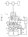
- a vehicle 1 includes an engine 10, a K0 clutch 12, a C1 clutch 14, a C2 clutch 16, a motor generator 22 (referred to as an MG 22 hereafter), an automatic transmission 23, a torque converter 24, a hydraulic circuit 26, an electric oil pump (EOP) 27, a mechanical oil pump (MOP) 28, a power control unit (PCU) 40, a battery 42, a drive wheel 72, and an electronic control unit (ECU) 100.
- an engine 10 a K0 clutch 12, a C1 clutch 14, a C2 clutch 16, a motor generator 22 (referred to as an MG 22 hereafter), an automatic transmission 23, a torque converter 24, a hydraulic circuit 26, an electric oil pump (EOP) 27, a mechanical oil pump (MOP) 28, a power control unit (PCU) 40, a battery 42, a drive wheel 72, and an electronic control unit (ECU) 100.
- EOP electric oil pump
- MOP mechanical oil pump
- ECU power control unit
- a crankshaft serving as an output shaft of the engine 10 and a rotary shaft of the MG 22 are connected via the K0 clutch 12.
- the rotary shaft of the MG 22 is connected to an input shaft of the torque converter 24.
- An output shaft of the torque converter 24 is connected to an input shaft of the automatic transmission 23.
- An output shaft of the automatic transmission 23 is connected to the drive wheel 72.
- the MG 22 is a three-phase alternating current rotating electric machine, for example.
- the MG 22 is driven by power supplied thereto from the battery 42 via the PCU 40.
- the MG 22 functions as both a motor that generates a driving force of the vehicle 1 and a starter that starts the engine 10.
- the torque converter 24 includes a pump impeller 24a, a turbine impeller 24b and a stator 24c.
- the pump impeller 24a is connected to the rotary shaft of the MG 22.
- the turbine impeller 24b is connected to the input shaft of the automatic transmission 23.
- the stator 24c is provided between the pump impeller 24a and the turbine impeller 24b.
- the automatic transmission 23 will be described as a stepped automatic transmission that switches a plurality of gear positions continuously, for example.
- a plurality of shift ranges is set in the automatic transmission 23.
- the plurality of shift ranges include, for example, a forward travel range (referred to as a D range hereafter), a reverse travel range (referred to as an R range hereafter), a parking range (referred to as a P range hereafter), and a neutral range (referred to as an N range hereafter).
- the D range is selected as the shift range, for example, one gear position from a first speed gear position to an upper limit gear position is established in the automatic transmission 23 in accordance with operating conditions of the vehicle 1.
- the automatic transmission 23 includes, for example, a speed change unit including one or a plurality of planetary gear mechanisms, and a plurality of engagement elements such as a brake that stops rotation of a rotary element of the planetary gear mechanism and a clutch that synchronizes the rotation of the rotary element with rotation of another rotary element.
- a speed change unit including one or a plurality of planetary gear mechanisms, and a plurality of engagement elements such as a brake that stops rotation of a rotary element of the planetary gear mechanism and a clutch that synchronizes the rotation of the rotary element with rotation of another rotary element.
- one of the plurality of engagement elements such as the brake and the clutch is disengaged or engaged in order to set a predetermined engagement element (or a predetermined combination of engagement elements) corresponding to the modified gear position in an engaged condition and set an engagement element other than the predetermined engagement element (or an engagement element other than the predetermined combination of engagement elements) in a disengaged condition.
- a ratio (a speed ratio) between the input shaft and the output shaft of the speed change unit (the automatic transmission 23) is modified, and as a result, the modified gear position is established.
- the automatic transmission 23 includes at least the C1 clutch 14 and the C2 clutch 16 as the plurality of engagement elements.
- the C1 clutch 14 is an engagement element that is engaged to cause the vehicle 1 to start to travel forward (in other words, when the D range is selected and the first speed is established as the gear position).
- the C2 clutch 16 is an engagement element that is engaged to cause the vehicle 1 to start to travel in reverse (in other words, when the R range is selected). Note that when the C1 clutch 14 is engaged, the C2 clutch 16 is disengaged, and when the C2 clutch 16 is engaged, the C1 clutch 14 is disengaged.
- the engine 10 is an internal combustion engine such as a gasoline engine or a diesel engine.
- the crankshaft of the engine 10 and the rotary shaft of the MG 22 are connected via the K0 clutch 12.
- the K0 clutch 12 is engaged to establish a power transmission condition between the engine 10 and the MG 22 and disengaged to establish a power cutoff condition between the engine 10 and the MG 22.
- the EOP 27 operates using a motor that is operated on the basis of a control signal from the ECU 100 as a power source.
- the MOP 28 operates in response to rotation of the pump impeller 24a using the engine 10 or the MG 22 as a power source.
- the EOP 27 and the MOP 28 both supply working oil stored in an oil pan 54 (see FIG. 2 ) to the hydraulic circuit 26.
- the hydraulic circuit 26 supplies the working oil to at least one of the K0 clutch 12, the C1 clutch 14, and the C2 clutch 16 on the basis of a control signal from the ECU 100.
- the K0 clutch 12, the C1 clutch 14, and the C2 clutch 16 are respectively engaged when a clutch piston is moved by oil pressure corresponding to the supplied amount of working oil supplied from the hydraulic circuit 26 such that friction is generated between two rotary bodies (a drive plate and a driven plate on which a friction material is provided) that receive and transmit power in each clutch, whereby a force for eliminating relative rotation between the two rotary bodies acts thereon (in other words, rotation of the two rotary bodies is synchronized).
- the ECU 100 controls the hydraulic circuit 26 to engage at least one of the K0 clutch 12, the C1 clutch 14, and the C2 clutch 16 in accordance with the operating conditions of the vehicle 1.
- the ECU 100 engages the K0 clutch 12.
- the power transmission condition is established between the engine 10 and the MG 22.
- the engine 10 can be operated by cranking the engine 10 using the MG 22 or, during coasting by the vehicle 1, cranking the engine 10 using the rotation of the rotary shaft of the MG 22.
- the vehicle 1 travels using power from the engine 10 or power from both the engine 10 and the MG 22.
- the battery 42 can be charged using power generated by operating the engine 10 or, during coasting by the vehicle 1, power generated in the MG 22.
- the ECU 100 issues requests to operate the engine 10 and stop the engine 10 in accordance with the operating conditions of the vehicle 1. For example, the ECU 100 may calculate a power (a required power) required by the vehicle 1 on the basis of an operation amount of an accelerator pedal (not shown) and a speed of the vehicle 1. The ECU 100 may then issue a request to operate the engine 10 when the required power exceeds a threshold, and issue a request to stop the engine 10 when the required power falls below the threshold.
- a power a required power
- an accelerator pedal not shown
- FIG. 2 shows a configuration of the hydraulic circuit 26.
- the hydraulic circuit 26 includes an oil pressure regulating valve 50, a first solenoid valve 56, a second solenoid valve 58, and a third solenoid valve 60.
- the working oil stored in the interior of the oil pan 54 is suctioned through a strainer 52 and discharged into the hydraulic circuit 26.
- the EOP 27 operates on the basis of a control signal M1 from the ECU 100.
- the oil pressure regulating valve 50 regulates an oil pressure of the working oil discharged from at least one of the EOP 27 and the MOP 28 to a predetermined oil pressure (a line pressure).
- the oil pressure regulated by the oil pressure regulating valve 50 is supplied respectively to the first solenoid valve 56, the second solenoid valve 58, and the third solenoid valve 60.
- the first solenoid valve 56 adjusts an oil pressure supplied to the K0 clutch 12 in accordance with an instructed pressure (referred to hereafter as a K0 instructed pressure) based on a control signal S1 from the ECU 100 using the oil pressure regulated by the oil pressure regulating valve 50 as a source pressure.
- a K0 instructed pressure an instructed pressure supplied to the K0 clutch 12 in accordance with an instructed pressure (referred to hereafter as a K0 instructed pressure) based on a control signal S1 from the ECU 100 using the oil pressure regulated by the oil pressure regulating valve 50 as a source pressure.
- the second solenoid valve 58 adjusts an oil pressure supplied to the C1 clutch 14 in accordance with an instructed pressure (referred to hereafter as a C1 instructed pressure) based on a control signal S2 from the ECU 100 using the oil pressure regulated by the oil pressure regulating valve 50 as a source pressure.
- a C1 instructed pressure an instructed pressure supplied to the C1 clutch 14 in accordance with an instructed pressure (referred to hereafter as a C1 instructed pressure) based on a control signal S2 from the ECU 100 using the oil pressure regulated by the oil pressure regulating valve 50 as a source pressure.
- the third solenoid valve 60 adjusts an oil pressure supplied to the C2 clutch 16 in accordance with an instructed pressure (referred to hereafter as a C2 instructed pressure) based on a control signal S3 from the ECU 100 using the oil pressure regulated by the oil pressure regulating valve 50 as a source pressure.
- a C2 instructed pressure an instructed pressure supplied to the C2 clutch 16 in accordance with an instructed pressure (referred to hereafter as a C2 instructed pressure) based on a control signal S3 from the ECU 100 using the oil pressure regulated by the oil pressure regulating valve 50 as a source pressure.
- a shift position sensor 200 that detects a position of a shift lever 202 is connected to the ECU 100.
- the shift position sensor 200 transmits a signal SHT indicating a detection result of the position of the shift lever 202 to the ECU 100.
- the ECU 100 specifies the shift range selected by a driver on the basis of the signal SHT from the shift position sensor 200. For example, when the driver moves the shift lever 202 to a position corresponding to the D range, the shift position sensor 200 transmits a signal SHT corresponding to the D range to the ECU 100. On the basis of the signal SHT from the shift position sensor, the ECU 100 specifies the D range as the shift range selected by the driver.
- the driver may issue a request to engage both the K0 clutch 12 and the C1 clutch 14 by greatly depressing the accelerator pedal or the like.
- the clutch pistons of the two clutches must be moved to positions in which the respective clutches enter the engaged condition, and for this purpose, a larger amount of working oil must be supplied than in a case where the clutches are operated singly.
- the ECU 100 engages the K0 clutch 12 on condition that the N range has been selected by the driver by operating the shift lever 202.
- the ECU 100 maintains the K0 clutch 12 in the engaged condition on condition that the N range is selected.
- the ECU 100 disengages the K0 clutch 12 when a request to operate the engine 10 has not been issued, and maintains the K0 clutch 12 in the engaged condition when a request to operate the engine 10 has been issued.
- the ECU 100 starts to engage the K0 clutch 12 after starting to engage the C2 clutch 16 on condition that the R range has been selected by the driver by operating the shift lever 202.
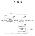
- FIG. 3 is a block diagram showing functions of the ECU 100 installed in the vehicle 1 according to this embodiment.
- the ECU 100 includes a shift operation determination unit 102, an oil pressure control unit 104, and an MG control unit 106. Note that these configurations may be realized by software such as programs, or by hardware.
- the shift operation determination unit 102 determines whether or not the N range has been selected (whether or not a D ⁇ N operation has been performed) in a case where the D range is set as the shift range on the basis of the signal SHT from the shift position sensor 200. After determining that the D ⁇ N operation has been performed, the shift operation determination unit 102 may set a D ⁇ N operation determination flag in an ON condition, for example.
- the shift operation determination unit 102 determines whether or not the D range has been selected (whether or not an N ⁇ D operation has been performed) in a case where the N range is set as the shift range on the basis of the signal SHT from the shift position sensor 200. After determining that the N ⁇ D operation has been performed, the shift operation determination unit 102 may set an N ⁇ D operation determination flag in an ON condition, for example.
- the shift operation determination unit 102 determines whether or not the R range has been selected (whether or not a D ⁇ R operation has been performed) in a case where the D range is set as the shift range on the basis of the signal SHT from the shift position sensor 200. After determining that the D ⁇ R operation has been performed, the shift operation determination unit 102 may set a D ⁇ R operation determination flag in an ON condition, for example.
- the shift operation determination unit 102 determines whether or not the D range has been selected (whether or not an R ⁇ D operation has been performed) in a case where the R range is set as the shift range on the basis of the signal SHT from the shift position sensor 200. After determining that the R ⁇ D operation has been performed, the shift operation determination unit 102 may set an R ⁇ D operation determination flag in an ON condition, for example.
- the oil pressure control unit 104 controls the hydraulic circuit 26 to disengage the C1 clutch 14 and engage the K0 clutch 12. Note that the oil pressure control unit 104 may disengage the C1 clutch 14 and start to engage the K0 clutch 12 when the D ⁇ N operation determination flag enters the ON condition, for example. Further, in the following description, control performed by the hydraulic circuit 26 to disengage a clutch will be referred to as disengagement control, and control performed by the hydraulic circuit 26 to engage a clutch will be referred to as engagement control.
- the oil pressure control unit 104 disengages the C1 clutch 14 and maintains the K0 clutch 12 in the engaged condition.
- the oil pressure control unit 104 executes the engagement control on the C1 clutch 14. Note that the oil pressure control unit 104 may start to engage the C1 clutch 14 when the N ⁇ D operation determination flag enters the ON condition, for example.
- the oil pressure control unit 104 executes the disengagement control on the K0 clutch 12 when a request to operate the engine 10 has not been issued, and maintains the K0 clutch 12 in the engaged condition by maintaining the K0 instructed pressure when a request to operate the engine 10 has been issued.
- the predetermined time ⁇ is a time during which the K0 clutch 12 is kept engaged in preparation for an engine operation request, and may be set at any time during which sufficient working oil is supplied to the C1 clutch 14 following the N ⁇ D operation so that a determination can be made as to whether or not a request to operate the engine 10 has been issued.
- the predetermined time ⁇ may be determined in advance or on the basis of the operating conditions of the vehicle 1.
- the oil pressure control unit 104 may control the oil pressure supplied to the K0 clutch 12 in accordance with whether or not a request to operate the engine 10 has been issued when the predetermined time ⁇ elapses after the N ⁇ D operation determination flag enters the ON condition, for example.
- the oil pressure control unit 104 executes the disengagement control on the C1 clutch 14 and the engagement control on the C2 clutch 16. Note that the oil pressure control unit 104 may execute the disengagement control on the C1 clutch 14 and the engagement control on the C2 clutch 16 when the D ⁇ R operation determination flag enters the ON condition, for example.
- the oil pressure control unit 104 executes the engagement control on the K0 clutch 12.
- the predetermined time ⁇ is preferably set at least at a longer time than a time required for the clutch piston of the C2 clutch 16 to complete a movement (a clutch stroke) to a position immediately before engagement following the D ⁇ R operation.
- the predetermined time ⁇ may be a time required for the C2 clutch 16 to complete engagement following selection of the R range.
- completion of the clutch stroke may be determined on the basis of a detection result from a sensor that detects a stroke amount of the clutch piston of the C2 clutch 16 or a detection result of a sensor that detects the oil pressure supplied to the C2 clutch 16 instead of a time.
- oil pressure control unit 104 may execute the engagement control on the K0 clutch 12 when the predetermined time ⁇ elapses after the D ⁇ R operation determination flag enters the ON condition.
- the oil pressure control unit 104 maintains the K0 clutch 12 in the engaged condition.
- the oil pressure control unit 104 executes the engagement control on the C1 clutch 14 and the disengagement control on the C2 clutch 16. Note that the oil pressure control unit 104 may execute the engagement control on the C1 clutch 14 and the disengagement control on the C2 clutch 16 when the R ⁇ D operation determination flag enters the ON condition, for example.
- the oil pressure control unit 104 executes the disengagement control on the K0 clutch 12 when a request to operate the engine 10 has not been issued, and maintains the K0 clutch 12 in the engaged condition when a request to operate the engine 10 has been issued.
- the oil pressure control unit 104 may control the oil pressure supplied to the K0 clutch 12 in accordance with whether or not a request to operate the engine 10 has been issued when the predetermined time ⁇ elapses after the R ⁇ D operation determination flag enters the ON condition, for example.
- the predetermined time ⁇ may be set at any time during which a determination can be made as to whether or not a request to operate the engine 10 has been issued following the R ⁇ D operation, and may be determined in advance or on the basis of the operating conditions of the vehicle 1.
- the MG control unit 106 controls an output torque of the MG 22 to ensure that torque variation generated by engaging the K0 clutch 12 is not transmitted to the drive wheel 72. More specifically, the MG control unit 106 controls the PCU 40 so that sufficient torque to make up for (compensate for) drag torque of the engine 10, which increases steadily as the K0 clutch 12 approaches the engaged condition, is generated in the MG 22.
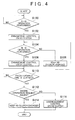
- step (steps will be referred to hereafter as S) 100 the ECU 100 determines whether or not the D ⁇ N operation has been performed. When it is determined that the D ⁇ N operation has been performed (YES in S100), the processing advances to S102. When it is determined that the D ⁇ N operation has not been performed (NO in S100), the processing returns to S100.
- the ECU 100 executes the engagement control on the K0 clutch 12.
- the ECU 100 determines whether or not the N ⁇ D operation has been performed. When it is determined that the N ⁇ D operation has been performed (YES in S104), the processing advances to S106. When it is determined that the N ⁇ D operation has not been performed (NO in S104), the processing advances to S108.
- the ECU 100 executes the engagement control on the C1 clutch 14.
- the ECU 100 maintains the K0 clutch 12 in the engaged condition.
- the ECU 100 determines whether or not the predetermined time ⁇ has elapsed following the N ⁇ D operation. When it is determined that the predetermined time ⁇ has elapsed (YES in S110), the processing advances to S 112. When it is determined that the predetermined time ⁇ has not elapsed (NO in S110), the processing returns to S110.
- the ECU 100 determines whether or not a request to operate the engine 10 has been issued. When it is determined that a request to operate the engine 10 has been issued (YES in S 112), the processing advances to S 114. When it is determined that a request to operate the engine 10 has not been issued (NO in S112), the processing advances to S116.
- the ECU 100 determines whether or not the D ⁇ R operation has been performed. When it is determined that the D ⁇ R operation has been performed (YES in S200), the processing advances to S202. When it is determined that the D ⁇ R operation has been performed (NO in S200), the processing returns to S200.
- the ECU 100 executes the disengagement control on the C1 clutch 14 and executes the engagement control on the C2 clutch 16.
- the ECU 100 determines whether or not the predetermined time ⁇ has elapsed following the D ⁇ R operation. When it is determined that the predetermined time ⁇ has elapsed following the D ⁇ R operation (YES in S204), the processing advances to S206. When it is determined that the predetermined time ⁇ has not elapsed e (NO in S204) the processing returns to S204.
- the ECU 100 executes the engagement control on the K0 clutch 12 together with the MG control.
- the ECU 100 determines whether or not the R ⁇ D operation has been performed. When it is determined that the R ⁇ D operation has been performed (YES in S208), the processing advances to S210. When it is determined that the R ⁇ D operation has not been performed (NO in S208), the processing advances to S212.
- the ECU 100 executes the engagement control on the C1 clutch 14 and executes the disengagement control on the C2 clutch 16.
- the ECU 100 maintains the K0 clutch 12 in the engaged condition.
- the ECU 100 determines whether or not the predetermined time ⁇ has elapsed following the R ⁇ D operation. When it is determined that the predetermined time ⁇ has elapsed following the R ⁇ D operation (YES in S214), the processing advances to S216. When it is determined that the predetermined time ⁇ has not elapsed (NO in S214), the processing returns to S214.
- the ECU 100 determines whether or not a request to operate the engine 10 has been issued. When it is determined that a request to operate the engine 10 has been issued (YES in S216), the processing advances to S218. When it is determined that a request to operate the engine 10 has not been issued (NO in S216), the processing advances to S220.
- the ECU 100 maintains the K0 clutch 12 in the engaged condition.
- the ECU 100 executes the disengagement control on the K0 clutch 12.
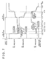
- the ECU 100 When the disengagement control is executed on the C1 clutch 14, the ECU 100 reduces the C1 instructed pressure in a single step to an oil pressure (zero, for example) corresponding to the disengaged condition of the C1 clutch 14. As a result, an actual pressure (referred to hereafter as a C1 actual pressure) of the C1 clutch 14 decreases over time in response to the variation in the C1 instructed pressure until the C1 clutch 14 enters the disengaged condition.
- a C1 actual pressure an actual pressure of the C1 clutch 14 decreases over time in response to the variation in the C1 instructed pressure until the C1 clutch 14 enters the disengaged condition.
- the ECU 100 sets the K0 instructed pressure at a predetermined initial pressure from the time T(0) to a time T(1). Then, from the time T(1) to a time T(2), the ECU 100 sets the K0 instructed pressure at a predetermined standby pressure that is lower than the predetermined initial pressure. Hence, from the time T(0) to the time T(2), working oil is supplied to the K0 clutch 12 such that the oil pressure of the K0 clutch 12 increases, and in response to this pressure increase, the clutch piston moves to the position immediately before engagement, whereby the stroke of the clutch piston is completed.
- the ECU 100 increases the K0 instructed pressure by a predetermined variation amount to an instructed pressure corresponding to the engaged condition.
- an actual pressure referred to hereafter as a K0 actual pressure
- the K0 clutch 12 increases in response to the variation in the K0 instructed pressure until the K0 clutch 12 enters the engaged condition.
- a period in which the predetermined initial pressure is output and a period in which the predetermined standby pressure is output may be determined either in advance or in accordance with the operating conditions of the vehicle 1. Further, the initial pressure, the standby pressure, and an amount by which the K0 instructed pressure is varied from the time T(3) onward may be determined in accordance with the operating conditions of the vehicle 1.
- the N ⁇ D operation is not performed (NO in S104) before a time T(4), and therefore the K0 clutch 12 is maintained in the engaged condition (S108).
- the engagement control is executed on the C 1 clutch 14 (S106).
- the ECU 100 increases the C1 instructed pressure in a single step to a predetermined instructed pressure at the time T(4), and then increases the C1 instructed pressure by a first variation amount from the time T(4) to a time T(5). Accordingly, the C1 actual pressure increases over time in response to the variation in the C1 instructed pressure. As a result, the clutch piston of the C1 clutch 14 moves to the position immediately before engagement, whereby the clutch stroke is completed.
- the ECU 100 increases the C1 instructed pressure in a single step by a second variation amount that is larger than the first variation amount.
- the C1 actual pressure increases over time in response to the variation in the C1 instructed pressure until the C1 clutch 14 enters the engaged condition.
- the K0 clutch 12 is maintained in the engaged condition.
- the predetermined time ⁇ elapses (YES in S110) at the time T(5), providing a request to operate the engine 10 has not been issued (NO in S 112) the disengagement control is executed on the K0 clutch 12.
- the predetermined time ⁇ may be of an identical length or a different length to a period required to increase the C1 instructed pressure by the second variation amount following the N ⁇ D operation.
- the ECU 100 When the disengagement control is executed on the K0 clutch 12, the ECU 100 reduces the K0 instructed pressure to a predetermined instructed pressure that is larger than an instructed pressure (zero, for example) corresponding to the disengaged condition, and then reduces the K0 instructed pressure by a predetermined variation amount. At a time T(6), the ECU 100 reduces the K0 instructed pressure to the instructed pressure corresponding to the disengaged condition. As a result, the K0 actual pressure decreases over time in response to the variation in the K0 instructed pressure until the K0 clutch 12 enters the disengaged condition.
- an instructed pressure zero, for example
- a period (the time T(0) to the time T(2)) in which the working oil supply amount is increased in order to move the clutch piston of the K0 clutch 12 can be prevented from overlapping a period (the time T(4) to the time T(5)) in which the working oil supply amount is increased in order to move the clutch piston of the C1 clutch 14. Therefore, when both the K0 clutch 12 and the C1 clutch 14 are engaged, the required working oil supply amount can be reduced in comparison with a case where the K0 clutch 12 and the C1 clutch 14 are engaged in parallel.
- the engaged condition is maintained in the C1 clutch 14 and the disengaged condition is maintained in the C2 clutch 16 is envisaged.
- the C2 instructed pressure varies in a similar manner to the manner in which the K0 instructed pressure varies during the engagement control executed on the K0 clutch 12, and therefore detailed description thereof will not be repeated.
- the ECU 100 outputs a predetermined initial pressure (the time T(10) to a time T(11)) and a predetermined standby pressure (the time T(11) to a time T(12)) to the third solenoid valve 60 as the C2 instructed pressure. Accordingly, working oil is supplied to the C2 clutch 16 such that an actual pressure (referred to hereafter as a C2 actual pressure) of the C2 clutch 16 increases over time in response to the variation in the C2 instructed pressure. As a result, the clutch piston of the C2 clutch 16 moves to the position immediately before engagement, whereby the clutch stroke is completed.
- the C2 actual pressure increases in response to the variation in the C2 instructed pressure, which is increased by a predetermined variation amount, until the C2 clutch 16 enters the engaged condition.
- the ECU 100 outputs a predetermined initial pressure (the time T(13) to a time T(14)) and a predetermined standby pressure (the time T(14) to a time T(15)) as the K0 instructed pressure, and then increases the K0 instructed pressure by a predetermined variation amount from the time T(15) to a time T(16).
- a predetermined initial pressure the time T(13) to a time T(14)
- a predetermined standby pressure the time T(14) to a time T(15)
- the K0 instructed pressure increases in response to the variation in the K0 instructed pressure until the K0 clutch 12 enters the engaged condition.
- the R ⁇ D operation is not performed (NO in S208) before a time T(17), and therefore the K0 clutch 12 is maintained in the engaged condition (S212).
- the ECU 100 increases the C1 instructed pressure by the first variation amount from the time T(17) to a time T(19). Accordingly, the C1 actual pressure increases over time in response to the variation in the C1 instructed pressure. As a result, the clutch piston of the C1 clutch 14 moves to the position immediately before engagement, whereby the clutch stroke is completed.
- the ECU 100 increases the C1 instructed pressure in a single step by the second variation amount.
- the C1 actual pressure increases over time in response to the variation in the C1 instructed pressure until the C1 clutch 14 enters the engaged condition.
- the ECU 100 When the disengagement control is executed on the C2 clutch 16, the ECU 100 reduces the C2 instructed pressure to a predetermined instructed pressure that is larger than the instructed pressure (zero, for example) corresponding to the disengaged condition, and then reduces the C2 instructed pressure by a predetermined variation amount. At a time T(18), the ECU 100 reduces the C2 instructed pressure to the instructed pressure corresponding to the disengaged condition. As a result, the C2 actual pressure decreases over time in response to the variation in the C2 instructed pressure until the C2 clutch 16 enters the disengaged condition.
- the K0 clutch 12 is maintained in the engaged condition.
- the predetermined time ⁇ elapses (YES in S214) at the time T(19), providing a request to operate the engine 10 has not been issued (NO in S216) the disengagement control is executed on the K0 clutch 12.
- the predetermined time ⁇ may be of an identical length or a different length to a period required to increase the C1 instructed pressure by the second variation amount following the R ⁇ D operation.
- the disengagement control executed on the K0 clutch 12 is as described above, and therefore detailed description thereof will not be repeated.
- the ECU 100 reduces the K0 instructed pressure to the instructed pressure corresponding to the disengaged condition.
- the K0 actual pressure decreases over time in response to variation in the K0 instructed pressure until the K0 clutch 12 enters the disengaged condition.
- a period (the time T(10) to the time T(12)) in which the working oil supply amount is increased in order to move the clutch piston of the C2 clutch 16 can be prevented from overlapping a period (the time T(13) to the time T(15)) in which the working oil supply amount is increased in order to move the clutch piston of the K0 clutch 12. Therefore, when both the C2 clutch 16 and the K0 clutch 12 are engaged, the required working oil supply amount can be reduced in comparison with a case where the C2 clutch 16 and the K0 clutch 12 are engaged in parallel.
- the period (the time T(13) to the time T(15)) in which the working oil supply amount is increased in order to move the clutch piston of the K0 clutch 12 can be prevented from overlapping a period (the time T(17) to the time T(19)) in which the working oil supply amount is increased in order to move the clutch piston of the C1 clutch 14. Therefore, when both the K0 clutch 12 and the C1 clutch 14 are engaged, the required working oil supply amount can be reduced in comparison with a case where the K0 clutch 12 and the C 1 clutch 14 are engaged in parallel.
- the driving apparatus for a hybrid vehicle As described above, by engaging the K0 clutch 12 on condition that the N range is selected, working oil can be supplied to the K0 clutch 12 before the D range is selected. More particularly, by engaging the K0 clutch 12, the amount of working oil required to complete the clutch stroke of the K0 clutch 12 can be supplied before the D range is selected. Hence, when the D range is selected thereafter such that working oil is supplied to the C1 clutch 14 during the engagement control of the C1 clutch 14, the amount of required working oil can be reduced in comparison with a case where the K0 clutch 12 and the C1 clutch 14 are engaged in parallel. As a result, a driving apparatus for a hybrid vehicle that appropriately controls a plurality of clutches configured to vary a power transmission condition between a power source and a drive wheel can be provided.
- the K0 clutch 12 is disengaged, and therefore a reduction in fuel efficiency can be suppressed. Moreover, when a request to start the engine 10 is issued after establishing the D range, the K0 clutch 12 is maintained in the engaged condition, and therefore the engine 10 can be started quickly.
- engagement of the K0 clutch 12 is started after starting to engage the C2 clutch 16.
- the engagement control is executed on the K0 clutch 12 after the clutch stroke of the C2 clutch 16 is completed. Therefore, at the point where the engagement control is executed on the K0 clutch 12, the amount of working oil required to complete the clutch stroke of the C2 clutch 16 has been supplied.
- the required amount of working oil can be reduced in comparison with a case where the K0 clutch 12 and the C2 clutch 16 are engaged in parallel.
- the MG control is executed together with engagement of the K0 clutch 12. Therefore, torque variation can be suppressed, with the result that shocks and noise can be prevented from occurring in the vehicle 1.
- the C1 clutch 14 when switching to the D range, the C1 clutch 14 can be engaged without a deficiency in the amount of working oil, and therefore deterioration of a startup response caused by slippage in the C1 clutch 14 and the K0 clutch 12 is suppressed.
- the K0 clutch 12 is engaged in the N range before switching to the D range, and therefore the engine 10 can be operated quickly when a request to operate the engine 10 is issued after switching to the D range. Since an increase in the working oil supply amount can be suppressed, a required performance of the EOP is prevented from increasing, and as a result, a cost increase can be suppressed.
- the ECU 100 may issue a request to operate the engine 10 when a state of charge (SOC) of the battery 42 falls below a threshold, and may issue a request to stop the engine 10 when the SOC of the battery 42 exceeds the threshold.
- SOC state of charge
- the ECU 100 may, for example, issue a request to operate the engine 10 when a predetermined accessory such as an air-conditioning apparatus or a defroster is operated, and may issue a request to stop the engine 10 when the predetermined accessory is stopped.
- a predetermined accessory such as an air-conditioning apparatus or a defroster
- the ECU 100 may issue a request to operate the engine 10 when, during cruise control, a speed difference between a current vehicle speed and a target vehicle speed exceeds a threshold, and may issue a request to stop the engine 10 when the speed difference falls below the threshold.
- the K0 clutch 12, the C1 clutch 14, and the C2 clutch 16 are all wet clutches was described, but at least one of the K0 clutch 12, the C 1 clutch 14, and the C2 clutch 16 may be a dry clutch.
- the subjects of the oil pressure regulation performed by the hydraulic circuit 26 are not limited to the K0 clutch 12, the C1 clutch 14, and the C2 clutch 16, and may include, for example, engagement elements that are engaged to establish gear positions other than the first speed, an actuator that adjusts a belt clamping pressure of a belt type continuously variable transmission, and so on.
- the K0 clutch 12 does not necessarily have to be set in the engaged condition in the N range and the R range.
- the K0 clutch 12 may be set in a half-engaged condition in the N range and the R range.
- the K0 clutch 12 may be engaged in another shift range from which a switch to the D range is possible, such as the P range, in addition to the N range and the R range.
- the automatic transmission 23 is a stepped automatic transmission having a planetary gear mechanism as the speed change unit, but the invention is not limited particularly thereto.
- the automatic transmission 23 may be a continuously variable transmission (CVT) in which the speed ratio is modified continuously using a belt or the like.
- the automatic transmission 23 may be an automated manual transmission, for example.
- the K0 clutch serving as a first engagement element is engaged in response to a request to operate the internal combustion engine, but the invention is not limited particularly thereto.
- the K0 clutch may be engaged when a shift from EV travel to HV travel is performed in response to an acceleration request or the like from the driver and so on, or in other words when any request to set the internal combustion engine and the motor in a power transmissible condition is issued.
- the modified examples described above may be combined partially or wholly and implemented in these combinations.
Abstract
Description
- The invention relates to a driving apparatus for a hybrid vehicle and a control method thereof.
- Japanese Patent Application Publication No.
2010-149538 JP 2010-149538 A - A hybrid vehicle, described in
JP 2010-149538A - The invention provides a driving apparatus for a hybrid vehicle and a control method thereof that appropriately controls a plurality of engagement elements configured to vary a power transmission condition between a power source and a drive wheel.
- A first aspect of the invention provides a driving apparatus for a hybrid vehicle, the driving apparatus includes an internal combustion engine, an electric motor, a speed change unit, a first engagement element, a second engagement element, an oil pressure source, a selection unit, an electronic control unit. The speed change unit is configured to transmit power from at least one of the internal combustion engine and the electric motor to a drive wheel of the hybrid vehicle. The first engagement element is configured to engage between the internal combustion engine and the electric motor to establish a first power transmission condition. The second engagement element is configured to engage between an input shaft and an output shaft of the speed change unit to establish a second power transmission condition. The second engagement element is configured to disengage between the input shaft and the output shaft to establish a power cutoff condition. The oil pressure source is configured to supply working oil to the first engagement element and the second engagement element. The selection unit is configured to supply any of a plurality of shift ranges. The plurality of shift ranges includes a first range and a second range. The first range is established by setting the second engagement element in an engaged condition. The second range is established by setting the second engagement element in a disengaged condition. The electronic control unit is configured to control the first engagement element to engage between the internal combustion engine and the electric motor when the second range is selected by the selection unit.
- By engaging the first engagement element when the second range is selected by the selection unit in this manner, working oil can be supplied to the first engagement element before the first range is selected. Therefore, when the first range is selected thereafter such that the second engagement element is engaged, an amount of required working oil can be reduced in comparison with a case where the first engagement element and the second engagement element are engaged in parallel.
- In the driving apparatus, the electronic control unit may be configured to control the first engagement element to disengage between the internal combustion engine and the electric motor when the first range is selected after establishing the second range and a request to operate the internal combustion engine has not been issued.
- Hence, when the first range is selected after establishing the second range and a request to operate the internal combustion engine has not been issued, the first engagement element is disengaged, and as a result, a reduction in fuel efficiency can be suppressed.
- In the driving apparatus, the electronic control unit may be configured to control the first engagement element to engage between the internal combustion engine and the electric motor on condition that the second range is selected by the selection unit.
- By engaging the first engagement element on condition that the second range is selected by the selection unit in this manner, working oil can be supplied to the first engagement element before the first range is selected. Therefore, when the first range is selected thereafter such that the second engagement element is engaged, the amount of required working oil can be reduced in comparison with a case where the first engagement element and the second engagement element are engaged in parallel.
- The driving apparatus, the electronic control unit may be configured to maintain the first engagement element in the engaged condition on condition that the second range is selected by the selection unit when the first engagement element is engaged.
- Hence, when the first range is selected after establishing the second range such that the second engagement element is engaged, the first engagement element is already in the engaged condition, and therefore the amount of required working oil can be reduced in comparison with a case where the first engagement element and the second engagement element are engaged in parallel. Moreover, since the first engagement element is in the engaged condition, the internal combustion engine can be operated quickly in response to a request to operate the internal combustion engine.
- In the driving apparatus, the electronic control unit may be configured to control the first engagement element to engage between the internal combustion engine and the electric motor on condition that the second range is selected by the selection unit when the first engagement element is not engaged.
- Hence, when the first range is selected after establishing the second range such that the second engagement element is engaged, the first engagement element is already in the engaged condition, and therefore the amount of required working oil can be reduced in comparison with a case where the first engagement element and the second engagement element are engaged in parallel. Moreover, since the first engagement element is in the engaged condition, the engine can be operated quickly in response to a request to operate the engine.
- In the driving apparatus, the electronic control unit may be configured to maintain the first engagement element in the engaged condition when the first range is selected after establishing the second range and a request to operate the internal combustion engine has been issued.
- Hence, when the first range is selected after establishing the second range and a request to operate the internal combustion engine has been issued, the first engagement element is maintained in the engaged condition, and therefore the internal combustion engine can be operated quickly.
- The driving apparatus may further includes a third engagement element. The third engagement element may be configured to engage between the input shaft and the output shaft of the speed change unit to establish a third power transmission condition. In the driving apparatus, the plurality of shift ranges may further include a third range, the third range may be established by setting the third engagement element in the engaged condition. The electronic control unit may be configured to start to control the first engagement element to engage between the internal combustion engine and the electric motor after starting to control the third engagement element to engage between the input shaft and the output shaft of the speed change unit on condition that the third range is selected by the selection unit.
- By starting to engage the first engagement element after starting to engage the third engagement element on condition that the third range is selected in this manner, the amount of required working oil can be reduced in comparison with a case where engagement of the first engagement element and engagement of the third engagement element are started simultaneously. Moreover, working oil can be supplied to the first engagement element before the first range is selected. Therefore, when the first range is selected thereafter such that the second engagement element is engaged, the amount of required working oil can be reduced in comparison with a case where the first engagement element and the second engagement element are engaged in parallel.
- In the driving apparatus, the electronic control unit may be configured to control the first engagement element to engage between the internal combustion engine and the electric motor after engaging the third engagement element when the third range is selected by the selection unit.
- Hence, when the third range is selected, the first engagement element is engaged after engaging the third engagement element, and therefore the amount of required working oil can be reduced in comparison with a case where the first engagement element and the third engagement element are engaged in parallel. Moreover, the first engagement element can be engaged before the first range is selected. Therefore, when the first range is selected thereafter such that the second engagement element is engaged, the amount of required working oil can be reduced in comparison with a case where the first engagement element and the second engagement element are engaged in parallel.
- In the driving apparatus, the first range may be a forward travel range, and the third range may be a reverse travel range.
- Hence, when the reverse travel range is established, engagement of the first engagement element is started before the forward travel range is selected. Therefore, when the forward travel range is selected thereafter such that the second engagement element is engaged, the amount of required working oil can be reduced in comparison with a case where the first engagement element and the second engagement element are engaged in parallel.
- A second aspect of the invention provides a control method for a hybrid vehicle. The hybrid vehicle includes a driving apparatus, an internal combustion engine, an electric motor, a speed change unit, a first engagement unit, a second engagement unit, an oil pressure source, a selection unit. The speed change unit is configured to transmit power from at least one of the internal combustion engine and the electric motor to a drive wheel of the hybrid vehicle. The first engagement element is configured to engage between the internal combustion engine and the electric motor to establish a first power transmission condition. The second engagement element is configured to engage between an input shaft and an output shaft of the speed change unit to establish a second power transmission condition, and the second engagement element is configured to disengage between the input shaft and the output shaft to establish a power cutoff condition. The oil pressure source is configured to supply working oil to the first engagement element and the second engagement element. The selection unit is configured to select any of a plurality of shift ranges, the plurality of shift ranges including a first range and a second range, the first range being established by setting the second engagement element in an engaged condition and the second range being established by setting the second engagement element in a disengaged condition. The control method includes engaging the first engagement element when the second range is selected by the selection unit.
- According to the invention, by engaging the first engagement element on condition that the second range is selected by the selection unit, working oil can be supplied to the first engagement element before the first range is selected. Therefore, when the first range is selected thereafter such that the second engagement element is engaged, the amount of required working oil can be reduced in comparison with a case where the first engagement element and the second engagement element are engaged in parallel. As a result, a driving apparatus for a hybrid vehicle that appropriately controls a plurality of clutches configured to vary a power transmission condition between a drive source and a drive wheel can be provided.
- Features, advantages, and technical and industrial significance of exemplary embodiments of the invention will be described below with reference to the accompanying drawings, in which like numerals denote like elements, and wherein:
-
FIG. 1 is a view showing a configuration of a hybrid vehicle according to one embodiment of the invention; -
FIG. 2 is a view showing a configuration of a hydraulic circuit of the embodiment; -
FIG. 3 is a block diagram showing functions of an electronic control unit (ECU) of the embodiment; -
FIG. 4 is a flowchart showing control processing executed by the ECU during a D→N operation of the embodiment; -
FIG. 5 is a flowchart showing control processing executed by the ECU during a D→R operation of the embodiment; -
FIG. 6 is a view illustrating an operation of the ECU during the D→N operation of the embodiment; and -
FIG. 7 is a view illustrating an operation of the ECU during the D→R operation of the embodiment. - An embodiment of the invention will be described below with reference to the drawings. In the following description, identical reference symbols have been allocated to identical components, names and functions of which are likewise identical. Accordingly, detailed description of these components will not be repeated.
- As shown in
FIG. 1 , avehicle 1 according to this embodiment includes anengine 10, aK0 clutch 12, aC1 clutch 14, aC2 clutch 16, a motor generator 22 (referred to as anMG 22 hereafter), an automatic transmission 23, atorque converter 24, ahydraulic circuit 26, an electric oil pump (EOP) 27, a mechanical oil pump (MOP) 28, a power control unit (PCU) 40, abattery 42, adrive wheel 72, and an electronic control unit (ECU) 100. - A crankshaft serving as an output shaft of the
engine 10 and a rotary shaft of theMG 22 are connected via theK0 clutch 12. The rotary shaft of theMG 22 is connected to an input shaft of thetorque converter 24. An output shaft of thetorque converter 24 is connected to an input shaft of the automatic transmission 23. An output shaft of the automatic transmission 23 is connected to thedrive wheel 72. - The
MG 22 is a three-phase alternating current rotating electric machine, for example. TheMG 22 is driven by power supplied thereto from thebattery 42 via thePCU 40. TheMG 22 functions as both a motor that generates a driving force of thevehicle 1 and a starter that starts theengine 10. - The
torque converter 24 includes apump impeller 24a, aturbine impeller 24b and astator 24c. Thepump impeller 24a is connected to the rotary shaft of theMG 22. Theturbine impeller 24b is connected to the input shaft of the automatic transmission 23. Thestator 24c is provided between thepump impeller 24a and theturbine impeller 24b. When a lockup clutch (not shown) is in an engaged condition, rotation of the input shaft and the output shaft of thetorque converter 24 is synchronized, and when the lockup clutch is in a disengaged condition, synchronization of the rotation is released. - In this embodiment, the automatic transmission 23 will be described as a stepped automatic transmission that switches a plurality of gear positions continuously, for example. A plurality of shift ranges is set in the automatic transmission 23. The plurality of shift ranges include, for example, a forward travel range (referred to as a D range hereafter), a reverse travel range (referred to as an R range hereafter), a parking range (referred to as a P range hereafter), and a neutral range (referred to as an N range hereafter).
- When the D range is selected as the shift range, for example, one gear position from a first speed gear position to an upper limit gear position is established in the automatic transmission 23 in accordance with operating conditions of the
vehicle 1. - The automatic transmission 23 includes, for example, a speed change unit including one or a plurality of planetary gear mechanisms, and a plurality of engagement elements such as a brake that stops rotation of a rotary element of the planetary gear mechanism and a clutch that synchronizes the rotation of the rotary element with rotation of another rotary element.
- When the gear position of the automatic transmission 23 is modified, one of the plurality of engagement elements such as the brake and the clutch is disengaged or engaged in order to set a predetermined engagement element (or a predetermined combination of engagement elements) corresponding to the modified gear position in an engaged condition and set an engagement element other than the predetermined engagement element (or an engagement element other than the predetermined combination of engagement elements) in a disengaged condition. In so doing, a ratio (a speed ratio) between the input shaft and the output shaft of the speed change unit (the automatic transmission 23) is modified, and as a result, the modified gear position is established.
- In this embodiment, the automatic transmission 23 includes at least the
C1 clutch 14 and the C2 clutch 16 as the plurality of engagement elements. - The
C1 clutch 14 is an engagement element that is engaged to cause thevehicle 1 to start to travel forward (in other words, when the D range is selected and the first speed is established as the gear position). TheC2 clutch 16 is an engagement element that is engaged to cause thevehicle 1 to start to travel in reverse (in other words, when the R range is selected). Note that when theC1 clutch 14 is engaged, theC2 clutch 16 is disengaged, and when theC2 clutch 16 is engaged, theC1 clutch 14 is disengaged. - The
engine 10 is an internal combustion engine such as a gasoline engine or a diesel engine. The crankshaft of theengine 10 and the rotary shaft of theMG 22 are connected via theK0 clutch 12. - The
K0 clutch 12 is engaged to establish a power transmission condition between theengine 10 and theMG 22 and disengaged to establish a power cutoff condition between theengine 10 and theMG 22. - The
EOP 27 operates using a motor that is operated on the basis of a control signal from theECU 100 as a power source. TheMOP 28 operates in response to rotation of thepump impeller 24a using theengine 10 or theMG 22 as a power source. TheEOP 27 and theMOP 28 both supply working oil stored in an oil pan 54 (seeFIG. 2 ) to thehydraulic circuit 26. - The
hydraulic circuit 26 supplies the working oil to at least one of theK0 clutch 12, theC1 clutch 14, and the C2 clutch 16 on the basis of a control signal from theECU 100. - The
K0 clutch 12, theC1 clutch 14, and the C2 clutch 16 are respectively engaged when a clutch piston is moved by oil pressure corresponding to the supplied amount of working oil supplied from thehydraulic circuit 26 such that friction is generated between two rotary bodies (a drive plate and a driven plate on which a friction material is provided) that receive and transmit power in each clutch, whereby a force for eliminating relative rotation between the two rotary bodies acts thereon (in other words, rotation of the two rotary bodies is synchronized). - The
ECU 100 controls thehydraulic circuit 26 to engage at least one of theK0 clutch 12, theC1 clutch 14, and the C2 clutch 16 in accordance with the operating conditions of thevehicle 1. - For example, when a request is issued to operate the
engine 10 while theK0 clutch 12 is disengaged and theengine 10 is stopped, theECU 100 engages theK0 clutch 12. As a result, the power transmission condition is established between theengine 10 and theMG 22. Accordingly, theengine 10 can be operated by cranking theengine 10 using theMG 22 or, during coasting by thevehicle 1, cranking theengine 10 using the rotation of the rotary shaft of theMG 22. When theengine 10 is operated, thevehicle 1 travels using power from theengine 10 or power from both theengine 10 and theMG 22. Further, thebattery 42 can be charged using power generated by operating theengine 10 or, during coasting by thevehicle 1, power generated in theMG 22. - When, on the other hand, a request is issued to stop the
engine 10 while theK0 clutch 12 is engaged and theengine 10 is operative, for example, theECU 100 disengages theK0 clutch 12 and stops the operation of theengine 10. - The
ECU 100 issues requests to operate theengine 10 and stop theengine 10 in accordance with the operating conditions of thevehicle 1. For example, theECU 100 may calculate a power (a required power) required by thevehicle 1 on the basis of an operation amount of an accelerator pedal (not shown) and a speed of thevehicle 1. TheECU 100 may then issue a request to operate theengine 10 when the required power exceeds a threshold, and issue a request to stop theengine 10 when the required power falls below the threshold. -
FIG. 2 shows a configuration of thehydraulic circuit 26. Thehydraulic circuit 26 includes an oilpressure regulating valve 50, afirst solenoid valve 56, asecond solenoid valve 58, and athird solenoid valve 60. - When at least one of the
EOP 27 and theMOP 28 is operated, the working oil stored in the interior of theoil pan 54 is suctioned through astrainer 52 and discharged into thehydraulic circuit 26. Note that theEOP 27 operates on the basis of a control signal M1 from theECU 100. - The oil
pressure regulating valve 50 regulates an oil pressure of the working oil discharged from at least one of theEOP 27 and theMOP 28 to a predetermined oil pressure (a line pressure). - The oil pressure regulated by the oil
pressure regulating valve 50 is supplied respectively to thefirst solenoid valve 56, thesecond solenoid valve 58, and thethird solenoid valve 60. - The
first solenoid valve 56 adjusts an oil pressure supplied to the K0 clutch 12 in accordance with an instructed pressure (referred to hereafter as a K0 instructed pressure) based on a control signal S1 from theECU 100 using the oil pressure regulated by the oilpressure regulating valve 50 as a source pressure. - The
second solenoid valve 58 adjusts an oil pressure supplied to the C1 clutch 14 in accordance with an instructed pressure (referred to hereafter as a C1 instructed pressure) based on a control signal S2 from theECU 100 using the oil pressure regulated by the oilpressure regulating valve 50 as a source pressure. - The
third solenoid valve 60 adjusts an oil pressure supplied to the C2 clutch 16 in accordance with an instructed pressure (referred to hereafter as a C2 instructed pressure) based on a control signal S3 from theECU 100 using the oil pressure regulated by the oilpressure regulating valve 50 as a source pressure. - A
shift position sensor 200 that detects a position of ashift lever 202 is connected to theECU 100. Theshift position sensor 200 transmits a signal SHT indicating a detection result of the position of theshift lever 202 to theECU 100. - The
ECU 100 specifies the shift range selected by a driver on the basis of the signal SHT from theshift position sensor 200. For example, when the driver moves theshift lever 202 to a position corresponding to the D range, theshift position sensor 200 transmits a signal SHT corresponding to the D range to theECU 100. On the basis of the signal SHT from the shift position sensor, theECU 100 specifies the D range as the shift range selected by the driver. - To switch the shift range from the N range to the D range, for example, while the
vehicle 1 having the above configuration is stopped, the driver may issue a request to engage both theK0 clutch 12 and the C1 clutch 14 by greatly depressing the accelerator pedal or the like. When working oil is supplied to both of the clutches in order to operate the clutches, the clutch pistons of the two clutches must be moved to positions in which the respective clutches enter the engaged condition, and for this purpose, a larger amount of working oil must be supplied than in a case where the clutches are operated singly. - Hence, in this embodiment, the
ECU 100 engages the K0 clutch 12 on condition that the N range has been selected by the driver by operating theshift lever 202. - Note that when the K0 clutch is engaged, the
ECU 100 maintains the K0 clutch 12 in the engaged condition on condition that the N range is selected. - Further, in a case where the D range is selected after establishing the N range, the
ECU 100 disengages the K0 clutch 12 when a request to operate theengine 10 has not been issued, and maintains the K0 clutch 12 in the engaged condition when a request to operate theengine 10 has been issued. - Furthermore, the
ECU 100 starts to engage the K0 clutch 12 after starting to engage the C2 clutch 16 on condition that the R range has been selected by the driver by operating theshift lever 202. -
FIG. 3 is a block diagram showing functions of theECU 100 installed in thevehicle 1 according to this embodiment. TheECU 100 includes a shiftoperation determination unit 102, an oilpressure control unit 104, and anMG control unit 106. Note that these configurations may be realized by software such as programs, or by hardware. - The shift
operation determination unit 102 determines whether or not the N range has been selected (whether or not a D→N operation has been performed) in a case where the D range is set as the shift range on the basis of the signal SHT from theshift position sensor 200. After determining that the D→N operation has been performed, the shiftoperation determination unit 102 may set a D→N operation determination flag in an ON condition, for example. - The shift
operation determination unit 102 determines whether or not the D range has been selected (whether or not an N→D operation has been performed) in a case where the N range is set as the shift range on the basis of the signal SHT from theshift position sensor 200. After determining that the N→D operation has been performed, the shiftoperation determination unit 102 may set an N→D operation determination flag in an ON condition, for example. - The shift
operation determination unit 102 determines whether or not the R range has been selected (whether or not a D→R operation has been performed) in a case where the D range is set as the shift range on the basis of the signal SHT from theshift position sensor 200. After determining that the D→R operation has been performed, the shiftoperation determination unit 102 may set a D→R operation determination flag in an ON condition, for example. - The shift
operation determination unit 102 determines whether or not the D range has been selected (whether or not an R→D operation has been performed) in a case where the R range is set as the shift range on the basis of the signal SHT from theshift position sensor 200. After determining that the R→D operation has been performed, the shiftoperation determination unit 102 may set an R→D operation determination flag in an ON condition, for example. - When the shift
operation determination unit 102 determines that the D→N operation has been performed and theK0 clutch 12 is disengaged, the oilpressure control unit 104 controls thehydraulic circuit 26 to disengage theC1 clutch 14 and engage theK0 clutch 12. Note that the oilpressure control unit 104 may disengage theC1 clutch 14 and start to engage the K0 clutch 12 when the D→N operation determination flag enters the ON condition, for example. Further, in the following description, control performed by thehydraulic circuit 26 to disengage a clutch will be referred to as disengagement control, and control performed by thehydraulic circuit 26 to engage a clutch will be referred to as engagement control. - Further, when the shift
operation determination unit 102 determines that the D→N operation has been performed and theK0 clutch 12 is engaged, the oilpressure control unit 104 disengages theC1 clutch 14 and maintains the K0 clutch 12 in the engaged condition. - When the shift
operation determination unit 102 determines that the N→D operation has been performed, the oilpressure control unit 104 executes the engagement control on theC1 clutch 14. Note that the oilpressure control unit 104 may start to engage the C1 clutch 14 when the N→D operation determination flag enters the ON condition, for example. - Once a predetermined time α has elapsed after it is determined that the N→D operation has been performed, the oil
pressure control unit 104 executes the disengagement control on the K0 clutch 12 when a request to operate theengine 10 has not been issued, and maintains the K0 clutch 12 in the engaged condition by maintaining the K0 instructed pressure when a request to operate theengine 10 has been issued. The predetermined time α is a time during which theK0 clutch 12 is kept engaged in preparation for an engine operation request, and may be set at any time during which sufficient working oil is supplied to theC1 clutch 14 following the N→D operation so that a determination can be made as to whether or not a request to operate theengine 10 has been issued. The predetermined time α may be determined in advance or on the basis of the operating conditions of thevehicle 1. - Note that the oil
pressure control unit 104 may control the oil pressure supplied to the K0 clutch 12 in accordance with whether or not a request to operate theengine 10 has been issued when the predetermined time α elapses after the N→D operation determination flag enters the ON condition, for example. - When the shift
operation determination unit 102 determines that the D→R operation has been performed, on the other hand, the oilpressure control unit 104 executes the disengagement control on theC1 clutch 14 and the engagement control on theC2 clutch 16. Note that the oilpressure control unit 104 may execute the disengagement control on theC1 clutch 14 and the engagement control on the C2 clutch 16 when the D→R operation determination flag enters the ON condition, for example. - When the
K0 clutch 12 is disengaged following the elapse of a predetermined time β after it is determined that the D→R operation has been performed, the oilpressure control unit 104 executes the engagement control on theK0 clutch 12. - The predetermined time β is preferably set at least at a longer time than a time required for the clutch piston of the C2 clutch 16 to complete a movement (a clutch stroke) to a position immediately before engagement following the D→R operation. For example, the predetermined time β may be a time required for the C2 clutch 16 to complete engagement following selection of the R range. Note that completion of the clutch stroke may be determined on the basis of a detection result from a sensor that detects a stroke amount of the clutch piston of the C2 clutch 16 or a detection result of a sensor that detects the oil pressure supplied to the C2 clutch 16 instead of a time.
- Note that the oil
pressure control unit 104 may execute the engagement control on the K0 clutch 12 when the predetermined time β elapses after the D→R operation determination flag enters the ON condition. - Further, when the
K0 clutch 12 is engaged following the elapse of the predetermined time β after it is determined that the D→R operation has been performed, the oilpressure control unit 104 maintains the K0 clutch 12 in the engaged condition. - When it is determined that the R→D operation has been performed, the oil
pressure control unit 104 executes the engagement control on theC1 clutch 14 and the disengagement control on theC2 clutch 16. Note that the oilpressure control unit 104 may execute the engagement control on theC1 clutch 14 and the disengagement control on the C2 clutch 16 when the R→D operation determination flag enters the ON condition, for example. - Once a predetermined time γ has elapsed after determining that the R→D operation has been performed, the oil
pressure control unit 104 executes the disengagement control on the K0 clutch 12 when a request to operate theengine 10 has not been issued, and maintains the K0 clutch 12 in the engaged condition when a request to operate theengine 10 has been issued. Note that the oilpressure control unit 104 may control the oil pressure supplied to the K0 clutch 12 in accordance with whether or not a request to operate theengine 10 has been issued when the predetermined time γ elapses after the R→D operation determination flag enters the ON condition, for example. The predetermined time γ may be set at any time during which a determination can be made as to whether or not a request to operate theengine 10 has been issued following the R→D operation, and may be determined in advance or on the basis of the operating conditions of thevehicle 1. - When the
K0 clutch 12 is engaged after determining that the R→D operation has been performed, theMG control unit 106 controls an output torque of theMG 22 to ensure that torque variation generated by engaging theK0 clutch 12 is not transmitted to thedrive wheel 72. More specifically, theMG control unit 106 controls thePCU 40 so that sufficient torque to make up for (compensate for) drag torque of theengine 10, which increases steadily as the K0 clutch 12 approaches the engaged condition, is generated in theMG 22. - Referring to
FIG. 4 , control processing executed during the D→N operation by theECU 100 installed in thevehicle 1 according to this embodiment will be described. - In step (steps will be referred to hereafter as S) 100, the
ECU 100 determines whether or not the D→N operation has been performed. When it is determined that the D→N operation has been performed (YES in S100), the processing advances to S102. When it is determined that the D→N operation has not been performed (NO in S100), the processing returns to S100. - In S102, the
ECU 100 executes the engagement control on theK0 clutch 12. In S104, theECU 100 determines whether or not the N→D operation has been performed. When it is determined that the N→D operation has been performed (YES in S104), the processing advances to S106. When it is determined that the N→D operation has not been performed (NO in S104), the processing advances to S108. - In S106, the
ECU 100 executes the engagement control on theC1 clutch 14. In S108, theECU 100 maintains the K0 clutch 12 in the engaged condition. - In S 110, the
ECU 100 determines whether or not the predetermined time α has elapsed following the N→D operation. When it is determined that the predetermined time α has elapsed (YES in S110), the processing advances to S 112. When it is determined that the predetermined time α has not elapsed (NO in S110), the processing returns to S110. - In S112, the
ECU 100 determines whether or not a request to operate theengine 10 has been issued. When it is determined that a request to operate theengine 10 has been issued (YES in S 112), the processing advances to S 114. When it is determined that a request to operate theengine 10 has not been issued (NO in S112), the processing advances to S116. - In S114, the
ECU 100 maintains the K0 clutch 12 in the engaged condition. In S116, theECU 100 executes the disengagement control on theK0 clutch 12. - Next, referring to
FIG. 5 , control processing executed during the D→R operation by theECU 100 installed in thevehicle 1 according to this embodiment will be described. - In S200, the
ECU 100 determines whether or not the D→R operation has been performed. When it is determined that the D→R operation has been performed (YES in S200), the processing advances to S202. When it is determined that the D→R operation has been performed (NO in S200), the processing returns to S200. - In S202, the
ECU 100 executes the disengagement control on theC1 clutch 14 and executes the engagement control on theC2 clutch 16. In S204, theECU 100 determines whether or not the predetermined time β has elapsed following the D→R operation. When it is determined that the predetermined time β has elapsed following the D→R operation (YES in S204), the processing advances to S206. When it is determined that the predetermined time β has not elapsed e (NO in S204) the processing returns to S204. - In S206, the
ECU 100 executes the engagement control on the K0 clutch 12 together with the MG control. In S208, theECU 100 determines whether or not the R→D operation has been performed. When it is determined that the R→D operation has been performed (YES in S208), the processing advances to S210. When it is determined that the R→D operation has not been performed (NO in S208), the processing advances to S212. - In S210, the
ECU 100 executes the engagement control on theC1 clutch 14 and executes the disengagement control on theC2 clutch 16. In S212, theECU 100 maintains the K0 clutch 12 in the engaged condition. - In S214, the
ECU 100 determines whether or not the predetermined time γ has elapsed following the R→D operation. When it is determined that the predetermined time γ has elapsed following the R→D operation (YES in S214), the processing advances to S216. When it is determined that the predetermined time γ has not elapsed (NO in S214), the processing returns to S214. - In S216, the
ECU 100 determines whether or not a request to operate theengine 10 has been issued. When it is determined that a request to operate theengine 10 has been issued (YES in S216), the processing advances to S218. When it is determined that a request to operate theengine 10 has not been issued (NO in S216), the processing advances to S220. - In S218, the
ECU 100 maintains the K0 clutch 12 in the engaged condition. In S220, theECU 100 executes the disengagement control on theK0 clutch 12. - Operations of the
ECU 100 installed in thevehicle 1 according to this embodiment, which are based on the structures and flowcharts described above, will now be described usingFIGS. 6 and7 . - A case in which the
K0 clutch 12 is in the disengaged condition and the selected shift range is the D range, for example, is envisaged. At this time, as shown inFIG. 6 , a case in which the engaged condition is maintained in theC1 clutch 14 is envisaged. - When the D→N operation is performed by the driver (YES in S100) at a time T(0), the disengagement control is executed on the
C1 clutch 14 and the engagement control is executed on the K0 clutch 12 (S102). - When the disengagement control is executed on the
C1 clutch 14, theECU 100 reduces the C1 instructed pressure in a single step to an oil pressure (zero, for example) corresponding to the disengaged condition of theC1 clutch 14. As a result, an actual pressure (referred to hereafter as a C1 actual pressure) of the C1 clutch 14 decreases over time in response to the variation in the C1 instructed pressure until theC1 clutch 14 enters the disengaged condition. - When the engagement control is executed on the
K0 clutch 12, theECU 100 sets the K0 instructed pressure at a predetermined initial pressure from the time T(0) to a time T(1). Then, from the time T(1) to a time T(2), theECU 100 sets the K0 instructed pressure at a predetermined standby pressure that is lower than the predetermined initial pressure. Hence, from the time T(0) to the time T(2), working oil is supplied to the K0 clutch 12 such that the oil pressure of the K0 clutch 12 increases, and in response to this pressure increase, the clutch piston moves to the position immediately before engagement, whereby the stroke of the clutch piston is completed. - From the time T(2) to a time T(3), the
ECU 100 increases the K0 instructed pressure by a predetermined variation amount to an instructed pressure corresponding to the engaged condition. As a result, an actual pressure (referred to hereafter as a K0 actual pressure) of the K0 clutch 12 increases in response to the variation in the K0 instructed pressure until theK0 clutch 12 enters the engaged condition. - Note that a period in which the predetermined initial pressure is output and a period in which the predetermined standby pressure is output may be determined either in advance or in accordance with the operating conditions of the
vehicle 1. Further, the initial pressure, the standby pressure, and an amount by which the K0 instructed pressure is varied from the time T(3) onward may be determined in accordance with the operating conditions of thevehicle 1. - The N→D operation is not performed (NO in S104) before a time T(4), and therefore the
K0 clutch 12 is maintained in the engaged condition (S108). When the N→D operation is performed (YES in S104) at the time T(4), the engagement control is executed on theC 1 clutch 14 (S106). - When the engagement control is started on the
C1 clutch 14, theECU 100 increases the C1 instructed pressure in a single step to a predetermined instructed pressure at the time T(4), and then increases the C1 instructed pressure by a first variation amount from the time T(4) to a time T(5). Accordingly, the C1 actual pressure increases over time in response to the variation in the C1 instructed pressure. As a result, the clutch piston of the C1 clutch 14 moves to the position immediately before engagement, whereby the clutch stroke is completed. - At the time T(5), the
ECU 100 increases the C1 instructed pressure in a single step by a second variation amount that is larger than the first variation amount. As a result, the C1 actual pressure increases over time in response to the variation in the C1 instructed pressure until theC1 clutch 14 enters the engaged condition. - From the time T(4) until the predetermined time α elapses (NO in S110), the
K0 clutch 12 is maintained in the engaged condition. When the predetermined time α elapses (YES in S110) at the time T(5), providing a request to operate theengine 10 has not been issued (NO in S 112), the disengagement control is executed on theK0 clutch 12. Note that the predetermined time α may be of an identical length or a different length to a period required to increase the C1 instructed pressure by the second variation amount following the N→D operation. - When the disengagement control is executed on the
K0 clutch 12, theECU 100 reduces the K0 instructed pressure to a predetermined instructed pressure that is larger than an instructed pressure (zero, for example) corresponding to the disengaged condition, and then reduces the K0 instructed pressure by a predetermined variation amount. At a time T(6), theECU 100 reduces the K0 instructed pressure to the instructed pressure corresponding to the disengaged condition. As a result, the K0 actual pressure decreases over time in response to the variation in the K0 instructed pressure until theK0 clutch 12 enters the disengaged condition. - Hence, a period (the time T(0) to the time T(2)) in which the working oil supply amount is increased in order to move the clutch piston of the K0 clutch 12 can be prevented from overlapping a period (the time T(4) to the time T(5)) in which the working oil supply amount is increased in order to move the clutch piston of the
C1 clutch 14. Therefore, when both theK0 clutch 12 and the C1 clutch 14 are engaged, the required working oil supply amount can be reduced in comparison with a case where theK0 clutch 12 and the C1 clutch 14 are engaged in parallel. - [Operation of
ECU 100 during D→R operation] - A case in which the
K0 clutch 12 is in the disengaged condition and the selected shift range is the D range, for example, is envisaged. At this time, as shown inFIG. 7 , a case in which the engaged condition is maintained in theC1 clutch 14 and the disengaged condition is maintained in theC2 clutch 16 is envisaged. - When the D→R operation is performed (YES in S200) at a time T(10), the disengagement control is executed on the
C1 clutch 14 and the engagement control is executed on the C2 clutch 16 (S202). Note that the disengagement control executed on theC1 clutch 14 is as described above, and therefore detailed description thereof will not be repeated. - Moreover, during the engagement control executed on the
C2 clutch 16, the C2 instructed pressure varies in a similar manner to the manner in which the K0 instructed pressure varies during the engagement control executed on theK0 clutch 12, and therefore detailed description thereof will not be repeated. - The
ECU 100 outputs a predetermined initial pressure (the time T(10) to a time T(11)) and a predetermined standby pressure (the time T(11) to a time T(12)) to thethird solenoid valve 60 as the C2 instructed pressure. Accordingly, working oil is supplied to the C2 clutch 16 such that an actual pressure (referred to hereafter as a C2 actual pressure) of the C2 clutch 16 increases over time in response to the variation in the C2 instructed pressure. As a result, the clutch piston of the C2 clutch 16 moves to the position immediately before engagement, whereby the clutch stroke is completed. - From the time T(12), the C2 actual pressure increases in response to the variation in the C2 instructed pressure, which is increased by a predetermined variation amount, until the
C2 clutch 16 enters the engaged condition. - At a time T(13), when the predetermined time β elapses (YES in S204) following the D→R operation, the engagement control is executed on the
K0 clutch 12 and the MG control is executed (S206). - The
ECU 100 outputs a predetermined initial pressure (the time T(13) to a time T(14)) and a predetermined standby pressure (the time T(14) to a time T(15)) as the K0 instructed pressure, and then increases the K0 instructed pressure by a predetermined variation amount from the time T(15) to a time T(16). Hence, from the time T(13) to the time T(14), the clutch piston of the K0 clutch 12 moves to the position immediately before engagement, whereby the clutch stroke is completed. From the time T(15), the K0 actual pressure increases in response to the variation in the K0 instructed pressure until theK0 clutch 12 enters the engaged condition. - The R→D operation is not performed (NO in S208) before a time T(17), and therefore the
K0 clutch 12 is maintained in the engaged condition (S212). - When the R→D operation is performed (YES in S208) at the time T(17), the engagement control is executed on the
C1 clutch 14 and the disengagement control is executed on the C2 clutch 16 (S210). - When the engagement control is started on the
C1 clutch 14, theECU 100 increases the C1 instructed pressure by the first variation amount from the time T(17) to a time T(19). Accordingly, the C1 actual pressure increases over time in response to the variation in the C1 instructed pressure. As a result, the clutch piston of the C1 clutch 14 moves to the position immediately before engagement, whereby the clutch stroke is completed. - At the time T(19), the
ECU 100 increases the C1 instructed pressure in a single step by the second variation amount. As a result, the C1 actual pressure increases over time in response to the variation in the C1 instructed pressure until theC1 clutch 14 enters the engaged condition. - When the disengagement control is executed on the
C2 clutch 16, theECU 100 reduces the C2 instructed pressure to a predetermined instructed pressure that is larger than the instructed pressure (zero, for example) corresponding to the disengaged condition, and then reduces the C2 instructed pressure by a predetermined variation amount. At a time T(18), theECU 100 reduces the C2 instructed pressure to the instructed pressure corresponding to the disengaged condition. As a result, the C2 actual pressure decreases over time in response to the variation in the C2 instructed pressure until theC2 clutch 16 enters the disengaged condition. - From the time T(17) until the predetermined time γ elapses (NO in S214), the
K0 clutch 12 is maintained in the engaged condition. When the predetermined time γ elapses (YES in S214) at the time T(19), providing a request to operate theengine 10 has not been issued (NO in S216), the disengagement control is executed on theK0 clutch 12. Note that the predetermined time γ may be of an identical length or a different length to a period required to increase the C1 instructed pressure by the second variation amount following the R→D operation. - The disengagement control executed on the
K0 clutch 12 is as described above, and therefore detailed description thereof will not be repeated. At a time T(20), theECU 100 reduces the K0 instructed pressure to the instructed pressure corresponding to the disengaged condition. As a result, the K0 actual pressure decreases over time in response to variation in the K0 instructed pressure until theK0 clutch 12 enters the disengaged condition. - Hence, a period (the time T(10) to the time T(12)) in which the working oil supply amount is increased in order to move the clutch piston of the C2 clutch 16 can be prevented from overlapping a period (the time T(13) to the time T(15)) in which the working oil supply amount is increased in order to move the clutch piston of the
K0 clutch 12. Therefore, when both theC2 clutch 16 and the K0 clutch 12 are engaged, the required working oil supply amount can be reduced in comparison with a case where theC2 clutch 16 and the K0 clutch 12 are engaged in parallel. - Furthermore, the period (the time T(13) to the time T(15)) in which the working oil supply amount is increased in order to move the clutch piston of the K0 clutch 12 can be prevented from overlapping a period (the time T(17) to the time T(19)) in which the working oil supply amount is increased in order to move the clutch piston of the
C1 clutch 14. Therefore, when both theK0 clutch 12 and the C1 clutch 14 are engaged, the required working oil supply amount can be reduced in comparison with a case where theK0 clutch 12 and theC 1 clutch 14 are engaged in parallel. - With the driving apparatus for a hybrid vehicle according to this embodiment, as described above, by engaging the K0 clutch 12 on condition that the N range is selected, working oil can be supplied to the K0 clutch 12 before the D range is selected. More particularly, by engaging the
K0 clutch 12, the amount of working oil required to complete the clutch stroke of the K0 clutch 12 can be supplied before the D range is selected. Hence, when the D range is selected thereafter such that working oil is supplied to the C1 clutch 14 during the engagement control of theC1 clutch 14, the amount of required working oil can be reduced in comparison with a case where theK0 clutch 12 and the C1 clutch 14 are engaged in parallel. As a result, a driving apparatus for a hybrid vehicle that appropriately controls a plurality of clutches configured to vary a power transmission condition between a power source and a drive wheel can be provided. - Further, when a request to start the
engine 10 is not issued after establishing the D range, theK0 clutch 12 is disengaged, and therefore a reduction in fuel efficiency can be suppressed. Moreover, when a request to start theengine 10 is issued after establishing the D range, theK0 clutch 12 is maintained in the engaged condition, and therefore theengine 10 can be started quickly. - Furthermore, engagement of the
K0 clutch 12 is started even when the R range is selected, and therefore, when the D range is selected thereafter such that working oil is supplied to the C1 clutch 14 during the engagement control of theC1 clutch 14, the amount of required working oil can be reduced in comparison with a case where theK0 clutch 12 and the C1 clutch 14 are engaged in parallel. - Moreover, on condition that the R range is selected, engagement of the
K0 clutch 12 is started after starting to engage theC2 clutch 16. In this embodiment in particular, the engagement control is executed on the K0 clutch 12 after the clutch stroke of theC2 clutch 16 is completed. Therefore, at the point where the engagement control is executed on theK0 clutch 12, the amount of working oil required to complete the clutch stroke of theC2 clutch 16 has been supplied. Hence, when working oil is supplied to the K0 clutch 12 during the engagement control of theK0 clutch 12, the required amount of working oil can be reduced in comparison with a case where theK0 clutch 12 and the C2 clutch 16 are engaged in parallel. - Further, when the R range is selected, the MG control is executed together with engagement of the
K0 clutch 12. Therefore, torque variation can be suppressed, with the result that shocks and noise can be prevented from occurring in thevehicle 1. - Furthermore, when switching to the D range, the C1 clutch 14 can be engaged without a deficiency in the amount of working oil, and therefore deterioration of a startup response caused by slippage in the
C1 clutch 14 and theK0 clutch 12 is suppressed. Moreover, theK0 clutch 12 is engaged in the N range before switching to the D range, and therefore theengine 10 can be operated quickly when a request to operate theengine 10 is issued after switching to the D range. Since an increase in the working oil supply amount can be suppressed, a required performance of the EOP is prevented from increasing, and as a result, a cost increase can be suppressed. - Modified examples will now be described. In this embodiment, a case in which the engagement control is executed on the K0 clutch 12 upon selection of the N range was described, but the engagement control may be executed on the
K0 clutch 12 following the elapse of a predetermined time after the N range is selected, for example. - In this embodiment, a case in which the
ECU 100 issues a request to operate theengine 10 when the required power, which is based on the operation amount of the accelerator pedal and the speed of thevehicle 1, exceeds the threshold and issues a request to stop theengine 10 when the required power falls below the threshold was described. However, issuance of the requests to operate and stop theengine 10 is not limited to these conditions in particular. - For example, the
ECU 100 may issue a request to operate theengine 10 when a state of charge (SOC) of thebattery 42 falls below a threshold, and may issue a request to stop theengine 10 when the SOC of thebattery 42 exceeds the threshold. - Alternatively, the
ECU 100 may, for example, issue a request to operate theengine 10 when a predetermined accessory such as an air-conditioning apparatus or a defroster is operated, and may issue a request to stop theengine 10 when the predetermined accessory is stopped. - Alternatively, the
ECU 100 may issue a request to operate theengine 10 when, during cruise control, a speed difference between a current vehicle speed and a target vehicle speed exceeds a threshold, and may issue a request to stop theengine 10 when the speed difference falls below the threshold. - In this embodiment, a case in which the
K0 clutch 12, theC1 clutch 14, and the C2 clutch 16 are all wet clutches was described, but at least one of theK0 clutch 12, theC 1 clutch 14, and the C2 clutch 16 may be a dry clutch. - In this embodiment, the subjects of the oil pressure regulation performed by the
hydraulic circuit 26 are not limited to theK0 clutch 12, theC1 clutch 14, and theC2 clutch 16, and may include, for example, engagement elements that are engaged to establish gear positions other than the first speed, an actuator that adjusts a belt clamping pressure of a belt type continuously variable transmission, and so on. - In this embodiment, a case in which the
K0 clutch 12 is engaged in the N range and the R range was described, but as long as enough working oil to complete the clutch stroke is supplied to the K0 clutch 12 in the N range and the R range, theK0 clutch 12 does not necessarily have to be set in the engaged condition in the N range and the R range. For example, the K0 clutch 12 may be set in a half-engaged condition in the N range and the R range. Further, the K0 clutch 12 may be engaged in another shift range from which a switch to the D range is possible, such as the P range, in addition to the N range and the R range. - In this embodiment, a case in which the
torque converter 24 is provided between theMG 22 and the automatic transmission 23 was described, but thetorque converter 24 may be omitted such that the rotary shaft of theMG 22 and the input shaft of the automatic transmission 23 are connected directly. - In this embodiment, a case in which the automatic transmission 23 is a stepped automatic transmission having a planetary gear mechanism as the speed change unit was described, but the invention is not limited particularly thereto. For example, the automatic transmission 23 may be a continuously variable transmission (CVT) in which the speed ratio is modified continuously using a belt or the like. Alternatively, the automatic transmission 23 may be an automated manual transmission, for example.
- In this embodiment, a case in which the K0 clutch serving as a first engagement element is engaged in response to a request to operate the internal combustion engine was described, but the invention is not limited particularly thereto. For example, the K0 clutch may be engaged when a shift from EV travel to HV travel is performed in response to an acceleration request or the like from the driver and so on, or in other words when any request to set the internal combustion engine and the motor in a power transmissible condition is issued. Note that the modified examples described above may be combined partially or wholly and implemented in these combinations.
- The embodiment disclosed herein is in all respects exemplary, and is not to be considered limiting. The scope of the invention is defined by the claims rather than the above description, and is intended to include all modifications having equivalent meanings and within the scope of the claims.
Claims (10)
- A driving apparatus for a hybrid vehicle (1), the driving apparatus characterized by comprising:an internal combustion engine (10);an electric motor (22);a speed change unit (23) configured to transmit power from at least one of the internal combustion engine and the electric motor to a drive wheel (72) of the hybrid vehicle;a first engagement element (12) configured to engage between the internal combustion engine and the electric motor to establish a first power transmission condition;a second engagement element (14) configured to engage between an input shaft and an output shaft of the speed change unit (23) to establish a second power transmission condition, and the second engagement element (14) being configured to disengage between the input shaft and the output shaft to establish a power cutoff condition;an oil pressure source (27, 28) configured to supply working oil to the first engagement element (12) and the second engagement element (14);a selection unit (202) configured to select any of a plurality of shift ranges (D, R, P, N), the plurality of shift ranges including a first range (D) and a second range (N), the first range (D) being established by setting the second engagement element (14) in an engaged condition and the second range (N) being established by setting the second engagement element (14) in a disengaged condition; andan electronic control unit (100) configured to control the first engagement element (12) to engage between the internal combustion engine (10) and the electric motor (22) when the second range is selected by the selection unit (202).
- The driving apparatus according to claim 1, wherein the electronic control unit (100) is configured to control the first engagement element (12) to disengage between the internal combustion engine (10) and the electric motor (22) when the first range is selected after establishing the second range and a request to operate the internal combustion engine (10) has not been issued.
- The driving apparatus according to claim 1 or 2, wherein the electronic control unit (100) is configured to control the first engagement element (12) to engage between the internal combustion engine (10) and the electric motor (22) on condition that the second range is selected by the selection unit (202).
- The driving apparatus according to any one of claims 1 to 3, wherein, the electronic control unit (100) is configured to maintain the first engagement element (12) in an engaged condition on condition that the second range is selected by the selection unit (202) when the first engagement element (12) is engaged.
- The driving apparatus according to any one of claims 1 to 4, wherein, the electronic control unit (100) is configured to control the first engagement element (12) to engage between the internal combustion engine (10) and the electric motor (22) on condition that the second range is selected by the selection unit (202) when the first engagement element (12) is not engaged.
- The driving apparatus according to any one of claims 1 to 5, wherein the electronic control unit (100) is configured to maintain the first engagement element (12) in an engaged condition when the first range is selected after establishing the second range and a request to operate the internal combustion engine (10) has been issued.
- The driving apparatus according to any one of claims 1 to 6, further comprises
a third engagement element (16) configured to engage between the input shaft and the output shaft of the speed change unit (23) to establish a third power transmission condition, wherein
the plurality of shift ranges further include a third range (R), the third range being established by setting the third engagement element (16) in an engaged condition, and
the electronic control unit is configured to start to control the first engagement element (12) to engage between the internal combustion engine (10) and the electric motor (22) after starting to control the third engagement element (16) to engage between the input shaft and the output shaft of the speed change unit (23) on condition that the third range (R) is selected by the selection unit (202). - The driving apparatus according to claim 7, wherein the electronic control unit (100) is configured to control the first engagement element (12) to engage between the internal combustion engine (10) and the electric motor (22) after engaging the third engagement element (16) when the third range (R) is selected by the selection unit (100).
- The driving apparatus according to claim 7 or 8, wherein
the first range is a forward travel range (D), and
the third range is a reverse travel range (R). - A control method for a hybrid vehicle (1), the hybrid vehicle including:a driving apparatus;an internal combustion engine (10);an electric motor (22);a speed change unit (23) configured to transmit power from at least one of the internal combustion engine (10) and the electric motor (22) to a drive wheel of the hybrid vehicle;a first engagement element (12) configured to engage between the internal combustion engine (10) and the electric motor (22) to establish a first power transmission condition;a second engagement element (14) configured to engage between an input shaft and an output shaft of the speed change unit (23) to establish a second power transmission condition, and the second engagement element (14) being configured to disengage between the input shaft and the output shaft to establish a power cutoff condition;an oil pressure source (27, 28) configured to supply working oil to the first engagement element (12) and the second engagement element (14); anda selection unit (202) configured to select any of a plurality of shift ranges (D, R, P, N), the plurality of shift ranges including a first range (D) and a second range (N), the first range (D) being established by setting the second engagement element (14) in an engaged condition and the second range (N) being established by setting the second engagement element (14) in a disengaged condition;the control method comprising
engaging the first engagement element (12) when the second range (N) is selected by the selection unit (202).
Applications Claiming Priority (1)
| Application Number | Priority Date | Filing Date | Title |
|---|---|---|---|
| JP2014105348A JP6348340B2 (en) | 2014-05-21 | 2014-05-21 | Drive device for hybrid vehicle |
Publications (2)
| Publication Number | Publication Date |
|---|---|
| EP2946979A1 true EP2946979A1 (en) | 2015-11-25 |
| EP2946979B1 EP2946979B1 (en) | 2018-05-09 |
Family
ID=53267237
Family Applications (1)
| Application Number | Title | Priority Date | Filing Date |
|---|---|---|---|
| EP15168762.1A Active EP2946979B1 (en) | 2014-05-21 | 2015-05-21 | Driving apparatus for hybrid vehicle and control method thereof |
Country Status (4)
| Country | Link |
|---|---|
| US (1) | US9561793B2 (en) |
| EP (1) | EP2946979B1 (en) |
| JP (1) | JP6348340B2 (en) |
| CN (1) | CN105082978B (en) |
Families Citing this family (7)
| Publication number | Priority date | Publication date | Assignee | Title |
|---|---|---|---|---|
| JP6512160B2 (en) * | 2016-04-19 | 2019-05-15 | トヨタ自動車株式会社 | Control device of power transmission device for vehicle |
| JP6544345B2 (en) | 2016-11-29 | 2019-07-17 | トヨタ自動車株式会社 | Control device for hybrid vehicle |
| JP7342736B2 (en) * | 2020-03-05 | 2023-09-12 | トヨタ自動車株式会社 | Hybrid vehicle drive system |
| US20220145971A1 (en) * | 2020-11-12 | 2022-05-12 | Ford Global Technologies, Llc | Hybrid vehicle with a combination electric machine and a torque converter |
| US11364786B2 (en) | 2020-11-12 | 2022-06-21 | Ford Global Technologies, Llc | Hybrid electric vehicle with a combined torque converter and an electric propulsion motor |
| JP7452469B2 (en) | 2021-03-04 | 2024-03-19 | トヨタ自動車株式会社 | Vehicle control device |
| CN115703454A (en) * | 2021-08-03 | 2023-02-17 | 丰田自动车株式会社 | Hybrid vehicle |
Citations (4)
| Publication number | Priority date | Publication date | Assignee | Title |
|---|---|---|---|---|
| JP2010149538A (en) | 2008-12-23 | 2010-07-08 | Toyota Motor Corp | Hydraulic control device of vehicle power transmission |
| US20130138282A1 (en) * | 2011-11-30 | 2013-05-30 | Kia Motors Corporation | Battery charging method and system for hybrid vehicle and the hybrid vehicle using the same |
| WO2013108847A1 (en) * | 2012-01-17 | 2013-07-25 | アイシン・エィ・ダブリュ株式会社 | Control device for vehicle drive device |
| WO2014051107A1 (en) * | 2012-09-28 | 2014-04-03 | アイシン・エィ・ダブリュ株式会社 | Control device of hybrid vehicle |
Family Cites Families (7)
| Publication number | Priority date | Publication date | Assignee | Title |
|---|---|---|---|---|
| JP4569493B2 (en) * | 2005-06-06 | 2010-10-27 | 日産自動車株式会社 | Oil pump drive control device for hybrid vehicle |
| JP2010155590A (en) * | 2009-01-05 | 2010-07-15 | Nissan Motor Co Ltd | Start control device for hybrid car |
| JP2010201962A (en) * | 2009-02-27 | 2010-09-16 | Nissan Motor Co Ltd | Controller for hybrid car |
| US8565990B2 (en) * | 2009-11-13 | 2013-10-22 | Ford Global Technologies, Llc. | Vehicle and method for controlling engine start in a vehicle |
| US9032825B2 (en) | 2010-03-31 | 2015-05-19 | Honda Motor Co., Ltd. | Vehicle driving system |
| WO2013125009A1 (en) * | 2012-02-23 | 2013-08-29 | トヨタ自動車株式会社 | Start control device for hybrid vehicle |
| US9145133B2 (en) * | 2013-11-08 | 2015-09-29 | Ford Global Technologies, Llc | Method and system for selecting an engine operating point for a hybrid vehicle |
-
2014
- 2014-05-21 JP JP2014105348A patent/JP6348340B2/en not_active Expired - Fee Related
-
2015
- 2015-05-14 US US14/712,085 patent/US9561793B2/en active Active
- 2015-05-21 CN CN201510263911.8A patent/CN105082978B/en active Active
- 2015-05-21 EP EP15168762.1A patent/EP2946979B1/en active Active
Patent Citations (4)
| Publication number | Priority date | Publication date | Assignee | Title |
|---|---|---|---|---|
| JP2010149538A (en) | 2008-12-23 | 2010-07-08 | Toyota Motor Corp | Hydraulic control device of vehicle power transmission |
| US20130138282A1 (en) * | 2011-11-30 | 2013-05-30 | Kia Motors Corporation | Battery charging method and system for hybrid vehicle and the hybrid vehicle using the same |
| WO2013108847A1 (en) * | 2012-01-17 | 2013-07-25 | アイシン・エィ・ダブリュ株式会社 | Control device for vehicle drive device |
| WO2014051107A1 (en) * | 2012-09-28 | 2014-04-03 | アイシン・エィ・ダブリュ株式会社 | Control device of hybrid vehicle |
Also Published As
| Publication number | Publication date |
|---|---|
| US9561793B2 (en) | 2017-02-07 |
| US20150336571A1 (en) | 2015-11-26 |
| CN105082978A (en) | 2015-11-25 |
| CN105082978B (en) | 2018-08-03 |
| JP6348340B2 (en) | 2018-06-27 |
| JP2015217914A (en) | 2015-12-07 |
| EP2946979B1 (en) | 2018-05-09 |
Similar Documents
| Publication | Publication Date | Title |
|---|---|---|
| EP2946979B1 (en) | Driving apparatus for hybrid vehicle and control method thereof | |
| CN107226079B (en) | Vehicle and control method for vehicle | |
| US9199632B2 (en) | Control device for hybrid vehicle | |
| EP3179125B1 (en) | Vehicle control device, and vehicle control method | |
| US9162676B2 (en) | Vehicle control device | |
| EP2829445B1 (en) | Vehicle control device | |
| US9234579B2 (en) | Control device and control method for vehicular electric oil pump | |
| US9656676B2 (en) | Vehicle travel control device | |
| US9435423B2 (en) | Oil supply device | |
| RU2610927C1 (en) | Hybrid vehicle control device | |
| JP6241424B2 (en) | Vehicle control device | |
| US20150072830A1 (en) | Hybrid Electric Vehicle Control Device | |
| US20140088813A1 (en) | Control device | |
| JP2022057978A (en) | Control device for vehicle | |
| CN114407863A (en) | Vehicle control device | |
| US10480478B2 (en) | Diagnostic techniques for a clutch interlock switch and a clutch pedal position sensor | |
| CN114347971A (en) | Vehicle control device | |
| JP6660217B2 (en) | Vehicle control device | |
| CN113734148B (en) | Hybrid vehicle | |
| US20220281437A1 (en) | Control device of vehicle | |
| JP2017100597A (en) | Vehicular control apparatus | |
| JP2023034416A (en) | Hybrid vehicle |
Legal Events
| Date | Code | Title | Description |
|---|---|---|---|
| PUAI | Public reference made under article 153(3) epc to a published international application that has entered the european phase |
Free format text: ORIGINAL CODE: 0009012 |
|
| 17P | Request for examination filed |
Effective date: 20150521 |
|
| AK | Designated contracting states |
Kind code of ref document: A1 Designated state(s): AL AT BE BG CH CY CZ DE DK EE ES FI FR GB GR HR HU IE IS IT LI LT LU LV MC MK MT NL NO PL PT RO RS SE SI SK SM TR |
|
| AX | Request for extension of the european patent |
Extension state: BA ME |
|
| STAA | Information on the status of an ep patent application or granted ep patent |
Free format text: STATUS: EXAMINATION IS IN PROGRESS |
|
| 17Q | First examination report despatched |
Effective date: 20170202 |
|
| GRAP | Despatch of communication of intention to grant a patent |
Free format text: ORIGINAL CODE: EPIDOSNIGR1 |
|
| STAA | Information on the status of an ep patent application or granted ep patent |
Free format text: STATUS: GRANT OF PATENT IS INTENDED |
|
| INTG | Intention to grant announced |
Effective date: 20171129 |
|
| GRAS | Grant fee paid |
Free format text: ORIGINAL CODE: EPIDOSNIGR3 |
|
| GRAA | (expected) grant |
Free format text: ORIGINAL CODE: 0009210 |
|
| STAA | Information on the status of an ep patent application or granted ep patent |
Free format text: STATUS: THE PATENT HAS BEEN GRANTED |
|
| AK | Designated contracting states |
Kind code of ref document: B1 Designated state(s): AL AT BE BG CH CY CZ DE DK EE ES FI FR GB GR HR HU IE IS IT LI LT LU LV MC MK MT NL NO PL PT RO RS SE SI SK SM TR |
|
| REG | Reference to a national code |
Ref country code: GB Ref legal event code: FG4D |
|
| REG | Reference to a national code |
Ref country code: CH Ref legal event code: EP Ref country code: AT Ref legal event code: REF Ref document number: 997315 Country of ref document: AT Kind code of ref document: T Effective date: 20180515 |
|
| REG | Reference to a national code |
Ref country code: IE Ref legal event code: FG4D |
|
| REG | Reference to a national code |
Ref country code: DE Ref legal event code: R096 Ref document number: 602015010859 Country of ref document: DE |
|
| REG | Reference to a national code |
Ref country code: FR Ref legal event code: PLFP Year of fee payment: 4 |
|
| REG | Reference to a national code |
Ref country code: NL Ref legal event code: MP Effective date: 20180509 |
|
| REG | Reference to a national code |
Ref country code: LT Ref legal event code: MG4D |
|
| REG | Reference to a national code |
Ref country code: DE Ref legal event code: R084 Ref document number: 602015010859 Country of ref document: DE |
|
| REG | Reference to a national code |
Ref country code: GB Ref legal event code: 746 Effective date: 20180927 |
|
| PG25 | Lapsed in a contracting state [announced via postgrant information from national office to epo] |
Ref country code: BG Free format text: LAPSE BECAUSE OF FAILURE TO SUBMIT A TRANSLATION OF THE DESCRIPTION OR TO PAY THE FEE WITHIN THE PRESCRIBED TIME-LIMIT Effective date: 20180809 Ref country code: FI Free format text: LAPSE BECAUSE OF FAILURE TO SUBMIT A TRANSLATION OF THE DESCRIPTION OR TO PAY THE FEE WITHIN THE PRESCRIBED TIME-LIMIT Effective date: 20180509 Ref country code: SE Free format text: LAPSE BECAUSE OF FAILURE TO SUBMIT A TRANSLATION OF THE DESCRIPTION OR TO PAY THE FEE WITHIN THE PRESCRIBED TIME-LIMIT Effective date: 20180509 Ref country code: NO Free format text: LAPSE BECAUSE OF FAILURE TO SUBMIT A TRANSLATION OF THE DESCRIPTION OR TO PAY THE FEE WITHIN THE PRESCRIBED TIME-LIMIT Effective date: 20180809 Ref country code: ES Free format text: LAPSE BECAUSE OF FAILURE TO SUBMIT A TRANSLATION OF THE DESCRIPTION OR TO PAY THE FEE WITHIN THE PRESCRIBED TIME-LIMIT Effective date: 20180509 Ref country code: LT Free format text: LAPSE BECAUSE OF FAILURE TO SUBMIT A TRANSLATION OF THE DESCRIPTION OR TO PAY THE FEE WITHIN THE PRESCRIBED TIME-LIMIT Effective date: 20180509 |
|
| PG25 | Lapsed in a contracting state [announced via postgrant information from national office to epo] |
Ref country code: NL Free format text: LAPSE BECAUSE OF FAILURE TO SUBMIT A TRANSLATION OF THE DESCRIPTION OR TO PAY THE FEE WITHIN THE PRESCRIBED TIME-LIMIT Effective date: 20180509 Ref country code: RS Free format text: LAPSE BECAUSE OF FAILURE TO SUBMIT A TRANSLATION OF THE DESCRIPTION OR TO PAY THE FEE WITHIN THE PRESCRIBED TIME-LIMIT Effective date: 20180509 Ref country code: HR Free format text: LAPSE BECAUSE OF FAILURE TO SUBMIT A TRANSLATION OF THE DESCRIPTION OR TO PAY THE FEE WITHIN THE PRESCRIBED TIME-LIMIT Effective date: 20180509 Ref country code: GR Free format text: LAPSE BECAUSE OF FAILURE TO SUBMIT A TRANSLATION OF THE DESCRIPTION OR TO PAY THE FEE WITHIN THE PRESCRIBED TIME-LIMIT Effective date: 20180810 Ref country code: LV Free format text: LAPSE BECAUSE OF FAILURE TO SUBMIT A TRANSLATION OF THE DESCRIPTION OR TO PAY THE FEE WITHIN THE PRESCRIBED TIME-LIMIT Effective date: 20180509 |
|
| REG | Reference to a national code |
Ref country code: CH Ref legal event code: PL |
|
| REG | Reference to a national code |
Ref country code: AT Ref legal event code: MK05 Ref document number: 997315 Country of ref document: AT Kind code of ref document: T Effective date: 20180509 |
|
| REG | Reference to a national code |
Ref country code: BE Ref legal event code: MM Effective date: 20180531 |
|
| PG25 | Lapsed in a contracting state [announced via postgrant information from national office to epo] |
Ref country code: EE Free format text: LAPSE BECAUSE OF FAILURE TO SUBMIT A TRANSLATION OF THE DESCRIPTION OR TO PAY THE FEE WITHIN THE PRESCRIBED TIME-LIMIT Effective date: 20180509 Ref country code: AT Free format text: LAPSE BECAUSE OF FAILURE TO SUBMIT A TRANSLATION OF THE DESCRIPTION OR TO PAY THE FEE WITHIN THE PRESCRIBED TIME-LIMIT Effective date: 20180509 Ref country code: DK Free format text: LAPSE BECAUSE OF FAILURE TO SUBMIT A TRANSLATION OF THE DESCRIPTION OR TO PAY THE FEE WITHIN THE PRESCRIBED TIME-LIMIT Effective date: 20180509 Ref country code: CZ Free format text: LAPSE BECAUSE OF FAILURE TO SUBMIT A TRANSLATION OF THE DESCRIPTION OR TO PAY THE FEE WITHIN THE PRESCRIBED TIME-LIMIT Effective date: 20180509 Ref country code: RO Free format text: LAPSE BECAUSE OF FAILURE TO SUBMIT A TRANSLATION OF THE DESCRIPTION OR TO PAY THE FEE WITHIN THE PRESCRIBED TIME-LIMIT Effective date: 20180509 Ref country code: SK Free format text: LAPSE BECAUSE OF FAILURE TO SUBMIT A TRANSLATION OF THE DESCRIPTION OR TO PAY THE FEE WITHIN THE PRESCRIBED TIME-LIMIT Effective date: 20180509 Ref country code: PL Free format text: LAPSE BECAUSE OF FAILURE TO SUBMIT A TRANSLATION OF THE DESCRIPTION OR TO PAY THE FEE WITHIN THE PRESCRIBED TIME-LIMIT Effective date: 20180509 |
|
| REG | Reference to a national code |
Ref country code: DE Ref legal event code: R097 Ref document number: 602015010859 Country of ref document: DE |
|
| RIC2 | Information provided on ipc code assigned after grant |
Ipc: B60K 6/48 20071001ALI20151022BHEP Ipc: B60W 20/00 20160101AFI20151022BHEP Ipc: B60K 6/547 20071001ALI20151022BHEP Ipc: B60W 30/18 20120101ALI20151022BHEP |
|
| REG | Reference to a national code |
Ref country code: IE Ref legal event code: MM4A |
|
| PG25 | Lapsed in a contracting state [announced via postgrant information from national office to epo] |
Ref country code: SM Free format text: LAPSE BECAUSE OF FAILURE TO SUBMIT A TRANSLATION OF THE DESCRIPTION OR TO PAY THE FEE WITHIN THE PRESCRIBED TIME-LIMIT Effective date: 20180509 Ref country code: CH Free format text: LAPSE BECAUSE OF NON-PAYMENT OF DUE FEES Effective date: 20180531 Ref country code: IT Free format text: LAPSE BECAUSE OF FAILURE TO SUBMIT A TRANSLATION OF THE DESCRIPTION OR TO PAY THE FEE WITHIN THE PRESCRIBED TIME-LIMIT Effective date: 20180509 Ref country code: LI Free format text: LAPSE BECAUSE OF NON-PAYMENT OF DUE FEES Effective date: 20180531 |
|
| PLBE | No opposition filed within time limit |
Free format text: ORIGINAL CODE: 0009261 |
|
| STAA | Information on the status of an ep patent application or granted ep patent |
Free format text: STATUS: NO OPPOSITION FILED WITHIN TIME LIMIT |
|
| PG25 | Lapsed in a contracting state [announced via postgrant information from national office to epo] |
Ref country code: MC Free format text: LAPSE BECAUSE OF FAILURE TO SUBMIT A TRANSLATION OF THE DESCRIPTION OR TO PAY THE FEE WITHIN THE PRESCRIBED TIME-LIMIT Effective date: 20180509 Ref country code: LU Free format text: LAPSE BECAUSE OF NON-PAYMENT OF DUE FEES Effective date: 20180521 |
|
| 26N | No opposition filed |
Effective date: 20190212 |
|
| PG25 | Lapsed in a contracting state [announced via postgrant information from national office to epo] |
Ref country code: IE Free format text: LAPSE BECAUSE OF NON-PAYMENT OF DUE FEES Effective date: 20180521 |
|
| PG25 | Lapsed in a contracting state [announced via postgrant information from national office to epo] |
Ref country code: BE Free format text: LAPSE BECAUSE OF NON-PAYMENT OF DUE FEES Effective date: 20180531 Ref country code: SI Free format text: LAPSE BECAUSE OF FAILURE TO SUBMIT A TRANSLATION OF THE DESCRIPTION OR TO PAY THE FEE WITHIN THE PRESCRIBED TIME-LIMIT Effective date: 20180509 |
|
| PG25 | Lapsed in a contracting state [announced via postgrant information from national office to epo] |
Ref country code: AL Free format text: LAPSE BECAUSE OF FAILURE TO SUBMIT A TRANSLATION OF THE DESCRIPTION OR TO PAY THE FEE WITHIN THE PRESCRIBED TIME-LIMIT Effective date: 20180509 |
|
| PG25 | Lapsed in a contracting state [announced via postgrant information from national office to epo] |
Ref country code: MT Free format text: LAPSE BECAUSE OF NON-PAYMENT OF DUE FEES Effective date: 20180521 |
|
| PG25 | Lapsed in a contracting state [announced via postgrant information from national office to epo] |
Ref country code: TR Free format text: LAPSE BECAUSE OF FAILURE TO SUBMIT A TRANSLATION OF THE DESCRIPTION OR TO PAY THE FEE WITHIN THE PRESCRIBED TIME-LIMIT Effective date: 20180509 |
|
| PG25 | Lapsed in a contracting state [announced via postgrant information from national office to epo] |
Ref country code: PT Free format text: LAPSE BECAUSE OF FAILURE TO SUBMIT A TRANSLATION OF THE DESCRIPTION OR TO PAY THE FEE WITHIN THE PRESCRIBED TIME-LIMIT Effective date: 20180509 |
|
| PG25 | Lapsed in a contracting state [announced via postgrant information from national office to epo] |
Ref country code: CY Free format text: LAPSE BECAUSE OF FAILURE TO SUBMIT A TRANSLATION OF THE DESCRIPTION OR TO PAY THE FEE WITHIN THE PRESCRIBED TIME-LIMIT Effective date: 20180509 Ref country code: HU Free format text: LAPSE BECAUSE OF FAILURE TO SUBMIT A TRANSLATION OF THE DESCRIPTION OR TO PAY THE FEE WITHIN THE PRESCRIBED TIME-LIMIT; INVALID AB INITIO Effective date: 20150521 Ref country code: MK Free format text: LAPSE BECAUSE OF NON-PAYMENT OF DUE FEES Effective date: 20180509 |
|
| PG25 | Lapsed in a contracting state [announced via postgrant information from national office to epo] |
Ref country code: IS Free format text: LAPSE BECAUSE OF FAILURE TO SUBMIT A TRANSLATION OF THE DESCRIPTION OR TO PAY THE FEE WITHIN THE PRESCRIBED TIME-LIMIT Effective date: 20180909 |
|
| PGFP | Annual fee paid to national office [announced via postgrant information from national office to epo] |
Ref country code: GB Payment date: 20220401 Year of fee payment: 8 Ref country code: FR Payment date: 20220408 Year of fee payment: 8 Ref country code: DE Payment date: 20220329 Year of fee payment: 8 |
|
| P01 | Opt-out of the competence of the unified patent court (upc) registered |
Effective date: 20230427 |
|
| REG | Reference to a national code |
Ref country code: DE Ref legal event code: R119 Ref document number: 602015010859 Country of ref document: DE |
|
| GBPC | Gb: european patent ceased through non-payment of renewal fee |
Effective date: 20230521 |