EP2946753A1 - Variable stiffness blanket with variable heating - Google Patents
Variable stiffness blanket with variable heating Download PDFInfo
- Publication number
- EP2946753A1 EP2946753A1 EP14175315.2A EP14175315A EP2946753A1 EP 2946753 A1 EP2946753 A1 EP 2946753A1 EP 14175315 A EP14175315 A EP 14175315A EP 2946753 A1 EP2946753 A1 EP 2946753A1
- Authority
- EP
- European Patent Office
- Prior art keywords
- fluid
- vest
- heater
- cavity
- bag
- Prior art date
- Legal status (The legal status is an assumption and is not a legal conclusion. Google has not performed a legal analysis and makes no representation as to the accuracy of the status listed.)
- Granted
Links
Images


Classifications
-
- H—ELECTRICITY
- H05—ELECTRIC TECHNIQUES NOT OTHERWISE PROVIDED FOR
- H05B—ELECTRIC HEATING; ELECTRIC LIGHT SOURCES NOT OTHERWISE PROVIDED FOR; CIRCUIT ARRANGEMENTS FOR ELECTRIC LIGHT SOURCES, IN GENERAL
- H05B3/00—Ohmic-resistance heating
- H05B3/20—Heating elements having extended surface area substantially in a two-dimensional [2D] plane, e.g. plate-heater
- H05B3/34—Heating elements having extended surface area substantially in a two-dimensional [2D] plane, e.g. plate-heater flexible, e.g. heating nets or webs
- H05B3/342—Heating elements having extended surface area substantially in a two-dimensional [2D] plane, e.g. plate-heater flexible, e.g. heating nets or webs heaters used in textiles
-
- A—HUMAN NECESSITIES
- A41—WEARING APPAREL
- A41D—OUTERWEAR; PROTECTIVE GARMENTS; ACCESSORIES
- A41D1/00—Garments
- A41D1/04—Vests, jerseys, sweaters or the like
-
- A—HUMAN NECESSITIES
- A41—WEARING APPAREL
- A41D—OUTERWEAR; PROTECTIVE GARMENTS; ACCESSORIES
- A41D13/00—Professional, industrial or sporting protective garments, e.g. surgeons' gowns or garments protecting against blows or punches
- A41D13/002—Professional, industrial or sporting protective garments, e.g. surgeons' gowns or garments protecting against blows or punches with controlled internal environment
- A41D13/005—Professional, industrial or sporting protective garments, e.g. surgeons' gowns or garments protecting against blows or punches with controlled internal environment with controlled temperature
- A41D13/0051—Heated garments
-
- A—HUMAN NECESSITIES
- A41—WEARING APPAREL
- A41D—OUTERWEAR; PROTECTIVE GARMENTS; ACCESSORIES
- A41D31/00—Materials specially adapted for outerwear
-
- A—HUMAN NECESSITIES
- A61—MEDICAL OR VETERINARY SCIENCE; HYGIENE
- A61F—FILTERS IMPLANTABLE INTO BLOOD VESSELS; PROSTHESES; DEVICES PROVIDING PATENCY TO, OR PREVENTING COLLAPSING OF, TUBULAR STRUCTURES OF THE BODY, e.g. STENTS; ORTHOPAEDIC, NURSING OR CONTRACEPTIVE DEVICES; FOMENTATION; TREATMENT OR PROTECTION OF EYES OR EARS; BANDAGES, DRESSINGS OR ABSORBENT PADS; FIRST-AID KITS
- A61F7/00—Heating or cooling appliances for medical or therapeutic treatment of the human body
- A61F7/007—Heating or cooling appliances for medical or therapeutic treatment of the human body characterised by electric heating
-
- F—MECHANICAL ENGINEERING; LIGHTING; HEATING; WEAPONS; BLASTING
- F41—WEAPONS
- F41H—ARMOUR; ARMOURED TURRETS; ARMOURED OR ARMED VEHICLES; MEANS OF ATTACK OR DEFENCE, e.g. CAMOUFLAGE, IN GENERAL
- F41H1/00—Personal protection gear
- F41H1/02—Armoured or projectile- or missile-resistant garments; Composite protection fabrics
-
- A—HUMAN NECESSITIES
- A61—MEDICAL OR VETERINARY SCIENCE; HYGIENE
- A61F—FILTERS IMPLANTABLE INTO BLOOD VESSELS; PROSTHESES; DEVICES PROVIDING PATENCY TO, OR PREVENTING COLLAPSING OF, TUBULAR STRUCTURES OF THE BODY, e.g. STENTS; ORTHOPAEDIC, NURSING OR CONTRACEPTIVE DEVICES; FOMENTATION; TREATMENT OR PROTECTION OF EYES OR EARS; BANDAGES, DRESSINGS OR ABSORBENT PADS; FIRST-AID KITS
- A61F7/00—Heating or cooling appliances for medical or therapeutic treatment of the human body
- A61F7/007—Heating or cooling appliances for medical or therapeutic treatment of the human body characterised by electric heating
- A61F2007/0071—Heating or cooling appliances for medical or therapeutic treatment of the human body characterised by electric heating using a resistor, e.g. near the spot to be heated
-
- A—HUMAN NECESSITIES
- A61—MEDICAL OR VETERINARY SCIENCE; HYGIENE
- A61F—FILTERS IMPLANTABLE INTO BLOOD VESSELS; PROSTHESES; DEVICES PROVIDING PATENCY TO, OR PREVENTING COLLAPSING OF, TUBULAR STRUCTURES OF THE BODY, e.g. STENTS; ORTHOPAEDIC, NURSING OR CONTRACEPTIVE DEVICES; FOMENTATION; TREATMENT OR PROTECTION OF EYES OR EARS; BANDAGES, DRESSINGS OR ABSORBENT PADS; FIRST-AID KITS
- A61F7/00—Heating or cooling appliances for medical or therapeutic treatment of the human body
- A61F7/02—Compresses or poultices for effecting heating or cooling
- A61F2007/0225—Compresses or poultices for effecting heating or cooling connected to the body or a part thereof
- A61F2007/0233—Compresses or poultices for effecting heating or cooling connected to the body or a part thereof connected to or incorporated in clothing or garments
- A61F2007/0234—Compresses or poultices for effecting heating or cooling connected to the body or a part thereof connected to or incorporated in clothing or garments for the upper part of the trunk, e.g. bodice
Definitions
- the present application relates generally to heater blankets, more specifically, to a heater blanket having variable stiffness.
- Heater blankets are well known in the art for providing warmth to an object.
- Conventional heater blankets typically include an electrical wire disposed within a thermal conductive body and when activated, the electrical energy traveling through the wire creates heat, which in turn warms the object that the heater blanket is place thereon.
- a heater blanket is utilized in the aircraft industry during repair of a laminate structure. For example, a plurality of repair plies are stacked and placed on a damaged composite surface and thereafter cured with the heater blanket. The heat from the heater blanket causes the adhesive disposed within the plies to cure.
- a common disadvantage with conventional heater blankets is the inability to retain the heater blanket in a fixed position on the plies without the use of straps and/or a vacuum bag. Further, conventional heater blankets are not always adapted to conform to the outer surface of the structure, thereby limiting use.
- the heater system of the present application overcomes the abovementioned problems commonly associated with conventional heater blankets.
- the heater system of the present application includes one or more fluid bladders having electrorheological fluid disposed therein, and when energized with an electrical charge, changes fluid viscosity. This feature enables the fluid bladder to conform to the contouring of the object that the heater system is attached thereto.
- the system is also provided with a heater blanket secured to the fluid bladder and configured to exude heat to warm the object that the bag is attached thereto. Further detailed description of these features are provided below and illustrated in the accompanying drawings.
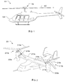
- FIG. 1 depicts an aircraft 101 in accordance with a preferred embodiment of the present application.
- aircraft 101 is a helicopter having a fuselage 103 and a rotor system 105 carried thereon.
- a plurality of rotor blades 107 is operably associated with rotor system 105 for creating flight.
- heater system is operably associated with a helicopter.
- system of the present application could also be utilized with different types of rotary aircraft, vehicles, clothing, medical devices, and the like in lieu of components of a helicopter.
- FIG. 2 illustrates a tiltrotor aircraft 201 that utilizes the heater system in accordance with the present application.
- Tiltrotor aircraft 201 includes rotor assemblies 213a and 213b that are carried by wings 215a and 215b, and are disposed at end portions 216a and 216b of wings 215a and 215b, respectively.
- Tilt rotor assemblies 213a and 213b include nacelles 220a and 220b, which carry the engines and transmissions of tilt rotor aircraft 201, as well as, rotor proprotors 219a and 219b on forward ends 221a and 221b of tilt rotor assemblies 213a and 213b, respectively.
- Tilt rotor assemblies 213a and 213b move or rotate relative to wing members 215a and 215b between a helicopter mode in which tilt rotor assemblies 213a and 213b are tilted upward, such that tilt rotor aircraft 201 flies like a conventional helicopter; and an airplane mode in which tilt rotor assemblies 213a and 213b are tilted forward, such that tilt rotor aircraft 201 flies like a conventional propeller driven aircraft.
- FIGS. 3-6 depict various views of a heater system 301 in accordance with a preferred embodiment of the present application.
- system 301 is shown operably associated with a rotor blade 107, as depicted in FIG. 7 .
- a body suit see FIG. 8
- a medical device see FIG. 10 .
- system 301 includes one or more of a bag 303 that forms a fluidly sealed interior area 305 configured to carry therein one or more fluid bladders 401 and a heater blanket 403.
- system 301 includes three fluid bladders 401, 405, 407 fluidly separated from each other. Disposed within each fluid chamber is an electrical wire 307 in fluid communication with the electrorheological fluid carried within the fluid bladders.
- One of the unique features believed characteristic of the present application is the use of electrorheological fluid carried within the fluid bladders. It should be appreciated that as an electrical charge is introduced into the fluid disposed within the fluid bladders, the fluid characteristics change, for example, the viscosity is altered.
- This feature provides significant advantages, namely, the bag 303 is placed on a contoured surface and retains that general shape of the contoured surface by altering the stiffness of the fluid disposed within bladders 401, 405, and 407.
- bag 303 is capable of retaining a shape without the need of a strap and/or a vacuum bag.
- fluidly separable fluid bladders to control the stiffness of each bladder.
- alternative embodiments could include a single fluid bladder in lieu of the preferred plurality of bladders. It will be appreciated that having multiple fluid bladders attached to each other allows selective controlling of the fluid characteristics in each chamber, individually. For example, a user could induce more electrical energy to fluid bladder 401 than for fluid bladder 407. This feature will increase the stiffness of fluid bladder 401 over the fluid bladder 407, thereby manipulating the stiffness of each bag individually for a desired overall stiffness of the bag, which in turn allows the bag to fit more snugly to the object being placed thereon.
- individual electrical wires 306, 307, and 308 pass through respective fluid bladders 405, 401, and 407 and could be electrically charged as individually. Thus, more electrical energy could pass through wire 307 than wire 308 to create greater stiffness in bag 401 than bag 407.
- the heater blanket is composed of thermal conductive material configured to warm the object that system 301 is placed thereon.
- an electrical wire 309 passes through the thermal conductive material of blanket 403 and is configured to create heat as an electrical current passes therethrough, which in turn warms the surface of the object placed thereon.
- FIGS. 6A-6D various views of different wire patterns are shown. It is contemplated having the wires travel in straight lines, as depicted in pattern 601, in the preferred embodiment; however, other patterns are considered in alternative embodiments.
- the wires can have a chevron pattern or as depicted in patter 605, a circular pattern or as depicted in 607, a wave pattern.
- the particular pattern of use is a design choice depending on the desired application of use.
- FIG. 7 a cross-sectional view of heater system 701 is shown operably associated with a damaged rotor blade 107. It will be appreciated that system 701 is substantially similar in form and function to system 301 and incorporates the features discussed above, and vice-versa.
- the heater system 701 includes a bag 703 configured to carry one or more fluid bladders 705 and a heater blanket 707. Wires 711, 713 provide electrical energy to respective fluid bladder 705 and heater blanket 707 during use.
- the bag 703 rests on a repair patch 715, and during use, the system 701 creates heat with heater blanket 707, which in turn heats repair patch 715, as depicted with an arrow.
- the fluid bladder 705 is configured to conform to the contouring of the blade 107 to create maximum surface contact between the heater blanket 707 and the repair patch 715.
- vest 801 includes a bag 803 that carries one or more fluid bladders 903 therein.
- the fluid bladders have the electrorheological fluid and a wire disposed therein.
- a projective 901 attempts to penetrate bag 801 but is stopped by fluid bladders 903 as an electrical charge is created therein via the wire 905.
- This feature is achieved by activating a power source (not shown) which provides electrical energy through the wires disposed within the fluid bladders 903, which in turn alters the viscosity and stiffness of the fluid disposed therein.
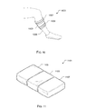
- medical device 1001 includes a bag 1003 substantially similar in form and function to one or more of the bags discussed above. Bag 1003 is secured to a leg 1005 of a patient via straps 1007, 1009 configured to wrap around the leg.
- a system 1101 is shown having three bags 1103, 1105, and 1107 secured together and configured to provide selective fluid viscosity and heat for each bag, individually. Bags 1103, 1105, and 1107 share the same features as one or more of the bags discussed above. Thus, in the contemplated embodiment, system 1101 provide means to create variable heat and stiffness of multiple bags used together.
Landscapes
- Engineering & Computer Science (AREA)
- Textile Engineering (AREA)
- Health & Medical Sciences (AREA)
- General Health & Medical Sciences (AREA)
- Heart & Thoracic Surgery (AREA)
- Physical Education & Sports Medicine (AREA)
- General Engineering & Computer Science (AREA)
- Biomedical Technology (AREA)
- Environmental & Geological Engineering (AREA)
- Vascular Medicine (AREA)
- Life Sciences & Earth Sciences (AREA)
- Animal Behavior & Ethology (AREA)
- Public Health (AREA)
- Veterinary Medicine (AREA)
- Thermotherapy And Cooling Therapy Devices (AREA)
- Surface Heating Bodies (AREA)
Abstract
Description
- The present application relates generally to heater blankets, more specifically, to a heater blanket having variable stiffness.
- Heater blankets are well known in the art for providing warmth to an object. Conventional heater blankets typically include an electrical wire disposed within a thermal conductive body and when activated, the electrical energy traveling through the wire creates heat, which in turn warms the object that the heater blanket is place thereon.
- In one application of use, a heater blanket is utilized in the aircraft industry during repair of a laminate structure. For example, a plurality of repair plies are stacked and placed on a damaged composite surface and thereafter cured with the heater blanket. The heat from the heater blanket causes the adhesive disposed within the plies to cure.
- A common disadvantage with conventional heater blankets is the inability to retain the heater blanket in a fixed position on the plies without the use of straps and/or a vacuum bag. Further, conventional heater blankets are not always adapted to conform to the outer surface of the structure, thereby limiting use.
- Although the foregoing developments in the field of heater blankets represent great strides, many shortcomings remain.
- The novel features believed characteristic of the embodiments of the present application are set forth in the appended claims. However, the embodiments themselves, as well as a preferred mode of use, and further objectives and advantages thereof, will best be understood by reference to the following detailed description when read in conjunction with the accompanying drawings, wherein:
-
FIG. 1 is a side view of a helicopter in accordance with a preferred embodiment of the present application; -
FIG. 2 is a perspective view of a tiltrotor aircraft according to an alternative embodiment of the present application; -
FIG. 3 is an oblique view of the heater blanket system in accordance with a preferred embodiment of the present application; -
FIG. 4 is a cross-sectional view of the system ofFIG. 3 taken at IV-IV; -
FIG. 5 is a cross-sectional view of the system ofFIG. 3 taken at V-V; -
FIGS. 6A, 6B, 6C, and 6D are simplified wiring schematics of the electrical wire of the system ofFIG. 3 ; -
FIG. 7 is a cross-sectional view of a heater blanket system in accordance with an alternative embodiment of the present application; -
FIG. 8 is an oblique view of a heater blanket system in accordance with an alternative embodiment of the present application; -
FIG. 9 is a partial cross-sectional view of the system ofFIG. 8 ; -
FIG. 10 is an oblique view of a heater blanket system in accordance with an alternative embodiment of the present application; and -
FIG. 11 is an oblique view of a heater blanket system in accordance with an alternative embodiment of the present application. - While the system and method of the present application is susceptible to various modifications and alternative forms, specific embodiments thereof have been shown by way of example in the drawings and are herein described in detail. It should be understood, however, that the description herein of specific embodiments is not intended to limit the invention to the particular embodiment disclosed, but on the contrary, the intention is to cover all modifications, equivalents, and alternatives falling within the spirit and scope of the process of the present application as defined by the appended claims.
- Illustrative embodiments of the apparatus and method are provided below. It will of course be appreciated that in the development of any actual embodiment, numerous implementation-specific decisions will be made to achieve the developer's specific goals, such as compliance with system-related and business-related constraints, which will vary from one implementation to another. Moreover, it will be appreciated that such a development effort might be complex and time-consuming, but would nevertheless be a routine undertaking for those of ordinary skill in the art having the benefit of this disclosure.
- The system of the present application overcomes the abovementioned problems commonly associated with conventional heater blankets. Specifically, the heater system of the present application includes one or more fluid bladders having electrorheological fluid disposed therein, and when energized with an electrical charge, changes fluid viscosity. This feature enables the fluid bladder to conform to the contouring of the object that the heater system is attached thereto. The system is also provided with a heater blanket secured to the fluid bladder and configured to exude heat to warm the object that the bag is attached thereto. Further detailed description of these features are provided below and illustrated in the accompanying drawings.
- The system and method of the present application will be understood, both as to its structure and operation, from the accompanying drawings, taken in conjunction with the accompanying description. Several embodiments of the system are presented herein. It should be understood that various components, parts, and features of the different embodiments may be combined together and/or interchanged with one another, all of which are within the scope of the present application, even though not all variations and particular embodiments are shown in the drawings. It should also be understood that the mixing and matching of features, elements, and/or functions between various embodiments is expressly contemplated herein so that one of ordinary skill in the art would appreciate from this disclosure that the features, elements, and/or functions of one embodiment may be incorporated into another embodiment as appropriate, unless described otherwise.
- Referring now to the drawings wherein like reference characters identify corresponding or similar elements throughout the several views,
FIG. 1 depicts anaircraft 101 in accordance with a preferred embodiment of the present application. In the exemplary embodiment,aircraft 101 is a helicopter having afuselage 103 and arotor system 105 carried thereon. A plurality ofrotor blades 107 is operably associated withrotor system 105 for creating flight. - In the contemplated embodiment, heater system is operably associated with a helicopter. However, it will be appreciated that the system of the present application could also be utilized with different types of rotary aircraft, vehicles, clothing, medical devices, and the like in lieu of components of a helicopter. For example,
FIG. 2 illustrates atiltrotor aircraft 201 that utilizes the heater system in accordance with the present application. -
Tiltrotor aircraft 201 includesrotor assemblies wings end portions wings Tilt rotor assemblies nacelles tilt rotor aircraft 201, as well as,rotor proprotors tilt rotor assemblies wing members tilt rotor aircraft 201 flies like a conventional helicopter; and an airplane mode in which tilt rotor assemblies 213a and 213b are tilted forward, such thattilt rotor aircraft 201 flies like a conventional propeller driven aircraft. -
FIGS. 3-6 depict various views of aheater system 301 in accordance with a preferred embodiment of the present application. In the contemplated embodiment,system 301 is shown operably associated with arotor blade 107, as depicted inFIG. 7 . However, it will be appreciated that the features discussed herein could be utilized on different devices, for example, a body suit (seeFIG. 8 ) or a medical device (seeFIG. 10 ). These and other contemplated embodiments incorporate the features discussed herein. - In the preferred embodiment,
system 301 includes one or more of abag 303 that forms a fluidly sealedinterior area 305 configured to carry therein one ormore fluid bladders 401 and aheater blanket 403. In the exemplary embodiment,system 301 includes threefluid bladders electrical wire 307 in fluid communication with the electrorheological fluid carried within the fluid bladders. - One of the unique features believed characteristic of the present application is the use of electrorheological fluid carried within the fluid bladders. It should be appreciated that as an electrical charge is introduced into the fluid disposed within the fluid bladders, the fluid characteristics change, for example, the viscosity is altered. This feature provides significant advantages, namely, the
bag 303 is placed on a contoured surface and retains that general shape of the contoured surface by altering the stiffness of the fluid disposed withinbladders bag 303 is capable of retaining a shape without the need of a strap and/or a vacuum bag. - In the exemplary embodiment, it is contemplated having fluidly separable fluid bladders to control the stiffness of each bladder. However, alternative embodiments could include a single fluid bladder in lieu of the preferred plurality of bladders. It will be appreciated that having multiple fluid bladders attached to each other allows selective controlling of the fluid characteristics in each chamber, individually. For example, a user could induce more electrical energy to
fluid bladder 401 than forfluid bladder 407. This feature will increase the stiffness offluid bladder 401 over thefluid bladder 407, thereby manipulating the stiffness of each bag individually for a desired overall stiffness of the bag, which in turn allows the bag to fit more snugly to the object being placed thereon. - In the contemplated embodiment, individual
electrical wires fluid bladders wire 307 thanwire 308 to create greater stiffness inbag 401 thanbag 407. - Another unique feature believed characteristic of the present application is the use of a
heater blanket 403 attached to the one or more fluid bladders. The heater blanket is composed of thermal conductive material configured to warm the object thatsystem 301 is placed thereon. To achieve this feature, anelectrical wire 309 passes through the thermal conductive material ofblanket 403 and is configured to create heat as an electrical current passes therethrough, which in turn warms the surface of the object placed thereon. - In
FIGS. 6A-6D , various views of different wire patterns are shown. It is contemplated having the wires travel in straight lines, as depicted inpattern 601, in the preferred embodiment; however, other patterns are considered in alternative embodiments. For example, as depicted inpattern 603, the wires can have a chevron pattern or as depicted inpatter 605, a circular pattern or as depicted in 607, a wave pattern. The particular pattern of use is a design choice depending on the desired application of use. - In
FIG. 7 , a cross-sectional view ofheater system 701 is shown operably associated with a damagedrotor blade 107. It will be appreciated thatsystem 701 is substantially similar in form and function tosystem 301 and incorporates the features discussed above, and vice-versa. - Like
system 301, theheater system 701 includes abag 703 configured to carry one or morefluid bladders 705 and aheater blanket 707.Wires respective fluid bladder 705 andheater blanket 707 during use. - As depicted, the
bag 703 rests on arepair patch 715, and during use, thesystem 701 creates heat withheater blanket 707, which in turn heatsrepair patch 715, as depicted with an arrow. Thefluid bladder 705 is configured to conform to the contouring of theblade 107 to create maximum surface contact between theheater blanket 707 and therepair patch 715. - It will be appreciated that the features of
systems proof vest 801. In the contemplated embodiment,vest 801 includes abag 803 that carries one or morefluid bladders 903 therein. The fluid bladders have the electrorheological fluid and a wire disposed therein. During use, a projective 901 attempts to penetratebag 801 but is stopped byfluid bladders 903 as an electrical charge is created therein via thewire 905. This feature is achieved by activating a power source (not shown) which provides electrical energy through the wires disposed within thefluid bladders 903, which in turn alters the viscosity and stiffness of the fluid disposed therein. - The features discussed herein could also be utilized with a
medical device 1001, as depicted inFIG. 10 . In the contemplated embodiment,medical device 1001 includes abag 1003 substantially similar in form and function to one or more of the bags discussed above.Bag 1003 is secured to aleg 1005 of a patient viastraps - In
FIG. 11 , asystem 1101 is shown having threebags Bags system 1101 provide means to create variable heat and stiffness of multiple bags used together. - It will be appreciated the features discussed herein, specifically, the altering of the electrorheological fluid and/or the amount of heat applied to a structure via the heater blanket, is variable. Thus, it is contemplated having the necessary electrical devices (not shown) that vary the amount of electrical energy provided to the electrorheological fluid and the heater blanket to create a desired fluid stiffness and/or heat source.
- It is apparent that a system and method with significant advantages has been described and illustrated. The particular embodiments disclosed above are illustrative only, as the embodiments may be modified and practiced in different but equivalent manners apparent to those skilled in the art having the benefit of the teachings herein. It is therefore evident that the particular embodiments disclosed above may be altered or modified, and all such variations are considered within the scope and spirit of the application. Accordingly, the protection sought herein is as set forth in the description. Although the present embodiments are shown above, they are not limited to just these embodiments, but are amenable to various changes and modifications without departing from the spirit thereof.
Claims (14)
- A heater system, comprising:a bag forming a cavity;a fluid bladder carried within the cavity and forming a fluidly sealed chamber, the fluid bladder being configured to store electrorheological fluid within a fluidly sealed chamber;an electrical wire in fluid communication with the electrorheological fluid; anda heater blanket carried within the cavity;wherein current passing through the electrical wire changes the fluid properties of the electrorheological fluid; andwherein the heater system creates heat, which in turn warms an object that the heater system is placed thereon.
- A vest comprising the heater system of claim 1.
- A vest, comprising:a bag forming a cavity;a fluid bladder carried within the cavity and forming a fluidly sealed chamber, the fluid bladder being configured to store electrorheological fluid within a fluidly sealed chamber; andan electrical wire in fluid communication with the electrorheological fluid;wherein current passing through the electrical wire changes the fluid properties of the electrorheological fluid.
- The system of claim 1 or the vest of claim 2 or of claim 3, wherein the heater blanket is composed of thermal conductive material, or
the vest of claim 3 further comprising a heater blanket, wherein the heater blanket is composed of thermal conductive material. - The system or vest of claim 4, further comprising:an electrical wire passing through thermal conductive material.
- The system or vest of claim 4, the heater system or vest comprising:an electrical wire configured to create heat to warm the object that the heater system or vest is placed thereon.
- The system of claim 1 or of any preceding claim, or the vest of claim 2 or of claim 3 or of any preceding claim, further comprising:a second bag secure to and placed adjacent to the bag.
- The system or vest of claim 7, further comprising:a second fluid bladder carried within a second cavity the second bag, the second fluid bladder being configured to form a fluidly sealed second chamber to store electrorheological fluid therein.
- The system or vest of claim 8, further comprising:a second electrical wire in fluid communication with the electrorheological fluid of the second fluid bladder.
- The system or vest of claim 9, further comprising:a second heater blanket carried within the second cavity.
- The vest of claim 2 or of claim 3, or of any preceding claim, further comprising:a heater blanket carried within the cavity of the bag;wherein the heater blanket creates heat, which in turn warms a surface that the vest is secured to.
- A method to heat a surface, comprising:creating a fluidly sealed chamber;storing a electrorheological fluid within the fluidly sealed chamber;altering the electrorheological fluid with an electrical current; andheating the surface with a heater blanket secured to the fluidly sealed chamber.
- The method of claim 12, wherein the feature of heating the surface is achieved by an electrical wire.
- The method of claim 12 or of claim 13, wherein the feature of altering the electrorheological fluid is achieved by passing an electrical wire through the fluidly sealed chamber.
Applications Claiming Priority (1)
| Application Number | Priority Date | Filing Date | Title |
|---|---|---|---|
| US14/283,555 US9585198B2 (en) | 2014-05-21 | 2014-05-21 | Variable stiffness blanket with variable heating |
Publications (2)
| Publication Number | Publication Date |
|---|---|
| EP2946753A1 true EP2946753A1 (en) | 2015-11-25 |
| EP2946753B1 EP2946753B1 (en) | 2016-03-30 |
Family
ID=51162485
Family Applications (1)
| Application Number | Title | Priority Date | Filing Date |
|---|---|---|---|
| EP14175315.2A Not-in-force EP2946753B1 (en) | 2014-05-21 | 2014-07-01 | Variable stiffness blanket with variable heating |
Country Status (2)
| Country | Link |
|---|---|
| US (1) | US9585198B2 (en) |
| EP (1) | EP2946753B1 (en) |
Cited By (1)
| Publication number | Priority date | Publication date | Assignee | Title |
|---|---|---|---|---|
| US20250162170A1 (en) * | 2023-11-17 | 2025-05-22 | The Boeing Company | Electrorheological Shape Retaining Membrane |
Families Citing this family (6)
| Publication number | Priority date | Publication date | Assignee | Title |
|---|---|---|---|---|
| US9541142B2 (en) * | 2014-01-31 | 2017-01-10 | Bell Helicopter Textron Inc. | Magnetorheological flight control clutch system |
| US9835414B2 (en) * | 2015-02-12 | 2017-12-05 | Blauer Manufacturing Company, Inc. | Ballistic vest carrier cover system with pouches for hard armor panels |
| US10485272B2 (en) * | 2015-02-12 | 2019-11-26 | Blauer Manufacturing Company, Inc. | Ballistic vest carrier cover with pouches for hard armor |
| US10710732B2 (en) | 2017-09-15 | 2020-07-14 | Bell Helicopter Textron Inc. | Rotary aircraft ice protection system |
| US11427335B2 (en) | 2018-11-13 | 2022-08-30 | Textron Innovations Inc. | Enclosure for contacts of aircraft wing heater blanket |
| CN111329595B (en) * | 2020-02-26 | 2021-01-29 | 吉林大学 | Gastroenterology scope center patient shifts case |
Citations (4)
| Publication number | Priority date | Publication date | Assignee | Title |
|---|---|---|---|---|
| US20060080756A1 (en) * | 2004-10-19 | 2006-04-20 | Goldfine Andrew A | Heated garment |
| US20060099808A1 (en) * | 2002-08-05 | 2006-05-11 | Sony Corporation | Electric viscous fluid device and electronic equipment |
| US20080306419A1 (en) * | 2004-08-06 | 2008-12-11 | Edward Timothy Bishop | Conformable Structures |
| US7550189B1 (en) * | 2004-08-13 | 2009-06-23 | Hrl Laboratories, Llc | Variable stiffness structure |
Family Cites Families (9)
| Publication number | Priority date | Publication date | Assignee | Title |
|---|---|---|---|---|
| US3397302A (en) * | 1965-12-06 | 1968-08-13 | Harry W. Hosford | Flexible sheet-like electric heater |
| US5561173A (en) * | 1990-06-19 | 1996-10-01 | Carolyn M. Dry | Self-repairing, reinforced matrix materials |
| US5148002A (en) * | 1991-03-14 | 1992-09-15 | Kuo David D | Multi-functional garment system |
| SE9402508L (en) * | 1994-07-18 | 1996-01-19 | Toecksfors Verkstads Ab | Electric heating device |
| US5545194A (en) * | 1994-09-30 | 1996-08-13 | Augustine Medical, Inc. | Convertible thermal blanket |
| US5800480A (en) * | 1996-08-30 | 1998-09-01 | Augustine Medical, Inc. | Support apparatus with a plurality of thermal zones providing localized cooling |
| EP1091709A4 (en) * | 1998-06-26 | 2004-07-07 | Hill Rom Co Inc | Heated patient support apparatus |
| KR100333491B1 (en) * | 2000-02-17 | 2002-04-25 | 최동환 | A electro-rheological fluids comprising dried water-soluble starch as a conductive particle |
| US10201935B2 (en) * | 2007-03-19 | 2019-02-12 | Augustine Temperature Management LLC | Electric heating pad |
-
2014
- 2014-05-21 US US14/283,555 patent/US9585198B2/en not_active Expired - Fee Related
- 2014-07-01 EP EP14175315.2A patent/EP2946753B1/en not_active Not-in-force
Patent Citations (4)
| Publication number | Priority date | Publication date | Assignee | Title |
|---|---|---|---|---|
| US20060099808A1 (en) * | 2002-08-05 | 2006-05-11 | Sony Corporation | Electric viscous fluid device and electronic equipment |
| US20080306419A1 (en) * | 2004-08-06 | 2008-12-11 | Edward Timothy Bishop | Conformable Structures |
| US7550189B1 (en) * | 2004-08-13 | 2009-06-23 | Hrl Laboratories, Llc | Variable stiffness structure |
| US20060080756A1 (en) * | 2004-10-19 | 2006-04-20 | Goldfine Andrew A | Heated garment |
Cited By (1)
| Publication number | Priority date | Publication date | Assignee | Title |
|---|---|---|---|---|
| US20250162170A1 (en) * | 2023-11-17 | 2025-05-22 | The Boeing Company | Electrorheological Shape Retaining Membrane |
Also Published As
| Publication number | Publication date |
|---|---|
| EP2946753B1 (en) | 2016-03-30 |
| US20150341989A1 (en) | 2015-11-26 |
| US9585198B2 (en) | 2017-02-28 |
Similar Documents
| Publication | Publication Date | Title |
|---|---|---|
| EP2946753B1 (en) | Variable stiffness blanket with variable heating | |
| US10858090B2 (en) | Systems and methods of constructing composite assemblies | |
| US7913952B2 (en) | Method and a device for de-icing an aircraft wall | |
| US20220192914A1 (en) | Pneumatic compression device with vibration and temperature control | |
| CA2844214C (en) | Hybrid fluid elastomeric damper | |
| CN102730194B (en) | Rotor blade deicing system | |
| US7891019B2 (en) | Heated garment | |
| US20180280190A1 (en) | Tri-modal localized heating garment | |
| US11046065B2 (en) | Membrane lamination of three-dimensional (3D) article | |
| CN110891499A (en) | Hemostat and tissue protection system | |
| US11331713B2 (en) | Bond fixture for composite splice fairing assembly | |
| US20160122013A1 (en) | Scissoring fold arrangement for dual plane four bladed rotor hubs | |
| EP2778055A2 (en) | High flapping yoke hub assembly using a cylindrical elastomeric attachment to avoid holes | |
| CA2942015C (en) | Method of forming pressure pad or other flexible element for use during cure of composite materials | |
| CN106904264A (en) | Pressure bulkhead | |
| EP3002100B1 (en) | Systems and methods for curing complex fiber-reinforced composite structures | |
| US10059064B2 (en) | Fiber orientation to allow for automated ply placement with composite rotor yokes | |
| EP2789535A1 (en) | Elastomeric damper with heater | |
| US10408544B2 (en) | Composite top case with embedded heat pipes | |
| EP3003081B1 (en) | Protective stretchable material and garment made therewith | |
| CA3060752A1 (en) | Heated control stick | |
| EP3058309A1 (en) | Aero control surfaces and method of use | |
| CN106275364A (en) | A kind of universal aerostatics value machine inflation/deflation all-in-one | |
| AT525472A1 (en) | Portable infrared heating device | |
| DE102017010859B4 (en) | A jacket that uses heat sensors to detect whether the wearer is cold and switches on the heating rods, which get their energy from solar cells on the shoulder and the rechargeable battery in the inside pocket, which can be removed so the jacket can be washed. |
Legal Events
| Date | Code | Title | Description |
|---|---|---|---|
| PUAI | Public reference made under article 153(3) epc to a published international application that has entered the european phase |
Free format text: ORIGINAL CODE: 0009012 |
|
| 17P | Request for examination filed |
Effective date: 20140701 |
|
| AK | Designated contracting states |
Kind code of ref document: A1 Designated state(s): AL AT BE BG CH CY CZ DE DK EE ES FI FR GB GR HR HU IE IS IT LI LT LU LV MC MK MT NL NO PL PT RO RS SE SI SK SM TR |
|
| AX | Request for extension of the european patent |
Extension state: BA ME |
|
| GRAP | Despatch of communication of intention to grant a patent |
Free format text: ORIGINAL CODE: EPIDOSNIGR1 |
|
| RIC1 | Information provided on ipc code assigned before grant |
Ipc: A41D 31/00 20060101ALI20151201BHEP Ipc: A41D 13/005 20060101ALI20151201BHEP Ipc: A41D 1/04 20060101ALI20151201BHEP Ipc: F41H 1/02 20060101ALI20151201BHEP Ipc: A61F 7/00 20060101AFI20151201BHEP Ipc: A61F 7/02 20060101ALN20151201BHEP Ipc: C10M 171/00 20060101ALI20151201BHEP Ipc: H05B 3/34 20060101ALI20151201BHEP |
|
| INTG | Intention to grant announced |
Effective date: 20151222 |
|
| GRAS | Grant fee paid |
Free format text: ORIGINAL CODE: EPIDOSNIGR3 |
|
| GRAA | (expected) grant |
Free format text: ORIGINAL CODE: 0009210 |
|
| AK | Designated contracting states |
Kind code of ref document: B1 Designated state(s): AL AT BE BG CH CY CZ DE DK EE ES FI FR GB GR HR HU IE IS IT LI LT LU LV MC MK MT NL NO PL PT RO RS SE SI SK SM TR |
|
| REG | Reference to a national code |
Ref country code: GB Ref legal event code: FG4D |
|
| REG | Reference to a national code |
Ref country code: CH Ref legal event code: EP |
|
| REG | Reference to a national code |
Ref country code: AT Ref legal event code: REF Ref document number: 784510 Country of ref document: AT Kind code of ref document: T Effective date: 20160415 |
|
| REG | Reference to a national code |
Ref country code: IE Ref legal event code: FG4D |
|
| REG | Reference to a national code |
Ref country code: DE Ref legal event code: R096 Ref document number: 602014001265 Country of ref document: DE |
|
| REG | Reference to a national code |
Ref country code: LT Ref legal event code: MG4D |
|
| REG | Reference to a national code |
Ref country code: FR Ref legal event code: PLFP Year of fee payment: 3 |
|
| PG25 | Lapsed in a contracting state [announced via postgrant information from national office to epo] |
Ref country code: FI Free format text: LAPSE BECAUSE OF FAILURE TO SUBMIT A TRANSLATION OF THE DESCRIPTION OR TO PAY THE FEE WITHIN THE PRESCRIBED TIME-LIMIT Effective date: 20160330 Ref country code: GR Free format text: LAPSE BECAUSE OF FAILURE TO SUBMIT A TRANSLATION OF THE DESCRIPTION OR TO PAY THE FEE WITHIN THE PRESCRIBED TIME-LIMIT Effective date: 20160701 Ref country code: NO Free format text: LAPSE BECAUSE OF FAILURE TO SUBMIT A TRANSLATION OF THE DESCRIPTION OR TO PAY THE FEE WITHIN THE PRESCRIBED TIME-LIMIT Effective date: 20160630 Ref country code: HR Free format text: LAPSE BECAUSE OF FAILURE TO SUBMIT A TRANSLATION OF THE DESCRIPTION OR TO PAY THE FEE WITHIN THE PRESCRIBED TIME-LIMIT Effective date: 20160330 |
|
| REG | Reference to a national code |
Ref country code: NL Ref legal event code: MP Effective date: 20160330 |
|
| REG | Reference to a national code |
Ref country code: AT Ref legal event code: MK05 Ref document number: 784510 Country of ref document: AT Kind code of ref document: T Effective date: 20160330 |
|
| PG25 | Lapsed in a contracting state [announced via postgrant information from national office to epo] |
Ref country code: RS Free format text: LAPSE BECAUSE OF FAILURE TO SUBMIT A TRANSLATION OF THE DESCRIPTION OR TO PAY THE FEE WITHIN THE PRESCRIBED TIME-LIMIT Effective date: 20160330 Ref country code: LV Free format text: LAPSE BECAUSE OF FAILURE TO SUBMIT A TRANSLATION OF THE DESCRIPTION OR TO PAY THE FEE WITHIN THE PRESCRIBED TIME-LIMIT Effective date: 20160330 Ref country code: SE Free format text: LAPSE BECAUSE OF FAILURE TO SUBMIT A TRANSLATION OF THE DESCRIPTION OR TO PAY THE FEE WITHIN THE PRESCRIBED TIME-LIMIT Effective date: 20160330 Ref country code: LT Free format text: LAPSE BECAUSE OF FAILURE TO SUBMIT A TRANSLATION OF THE DESCRIPTION OR TO PAY THE FEE WITHIN THE PRESCRIBED TIME-LIMIT Effective date: 20160330 |
|
| PG25 | Lapsed in a contracting state [announced via postgrant information from national office to epo] |
Ref country code: NL Free format text: LAPSE BECAUSE OF FAILURE TO SUBMIT A TRANSLATION OF THE DESCRIPTION OR TO PAY THE FEE WITHIN THE PRESCRIBED TIME-LIMIT Effective date: 20160330 |
|
| PG25 | Lapsed in a contracting state [announced via postgrant information from national office to epo] |
Ref country code: PL Free format text: LAPSE BECAUSE OF FAILURE TO SUBMIT A TRANSLATION OF THE DESCRIPTION OR TO PAY THE FEE WITHIN THE PRESCRIBED TIME-LIMIT Effective date: 20160330 Ref country code: IS Free format text: LAPSE BECAUSE OF FAILURE TO SUBMIT A TRANSLATION OF THE DESCRIPTION OR TO PAY THE FEE WITHIN THE PRESCRIBED TIME-LIMIT Effective date: 20160730 Ref country code: EE Free format text: LAPSE BECAUSE OF FAILURE TO SUBMIT A TRANSLATION OF THE DESCRIPTION OR TO PAY THE FEE WITHIN THE PRESCRIBED TIME-LIMIT Effective date: 20160330 |
|
| PG25 | Lapsed in a contracting state [announced via postgrant information from national office to epo] |
Ref country code: CZ Free format text: LAPSE BECAUSE OF FAILURE TO SUBMIT A TRANSLATION OF THE DESCRIPTION OR TO PAY THE FEE WITHIN THE PRESCRIBED TIME-LIMIT Effective date: 20160330 Ref country code: ES Free format text: LAPSE BECAUSE OF FAILURE TO SUBMIT A TRANSLATION OF THE DESCRIPTION OR TO PAY THE FEE WITHIN THE PRESCRIBED TIME-LIMIT Effective date: 20160330 Ref country code: RO Free format text: LAPSE BECAUSE OF FAILURE TO SUBMIT A TRANSLATION OF THE DESCRIPTION OR TO PAY THE FEE WITHIN THE PRESCRIBED TIME-LIMIT Effective date: 20160330 Ref country code: SM Free format text: LAPSE BECAUSE OF FAILURE TO SUBMIT A TRANSLATION OF THE DESCRIPTION OR TO PAY THE FEE WITHIN THE PRESCRIBED TIME-LIMIT Effective date: 20160330 Ref country code: PT Free format text: LAPSE BECAUSE OF FAILURE TO SUBMIT A TRANSLATION OF THE DESCRIPTION OR TO PAY THE FEE WITHIN THE PRESCRIBED TIME-LIMIT Effective date: 20160801 Ref country code: SK Free format text: LAPSE BECAUSE OF FAILURE TO SUBMIT A TRANSLATION OF THE DESCRIPTION OR TO PAY THE FEE WITHIN THE PRESCRIBED TIME-LIMIT Effective date: 20160330 Ref country code: AT Free format text: LAPSE BECAUSE OF FAILURE TO SUBMIT A TRANSLATION OF THE DESCRIPTION OR TO PAY THE FEE WITHIN THE PRESCRIBED TIME-LIMIT Effective date: 20160330 |
|
| PG25 | Lapsed in a contracting state [announced via postgrant information from national office to epo] |
Ref country code: BE Free format text: LAPSE BECAUSE OF FAILURE TO SUBMIT A TRANSLATION OF THE DESCRIPTION OR TO PAY THE FEE WITHIN THE PRESCRIBED TIME-LIMIT Effective date: 20160330 |
|
| REG | Reference to a national code |
Ref country code: DE Ref legal event code: R097 Ref document number: 602014001265 Country of ref document: DE |
|
| PG25 | Lapsed in a contracting state [announced via postgrant information from national office to epo] |
Ref country code: DK Free format text: LAPSE BECAUSE OF FAILURE TO SUBMIT A TRANSLATION OF THE DESCRIPTION OR TO PAY THE FEE WITHIN THE PRESCRIBED TIME-LIMIT Effective date: 20160330 |
|
| PLBE | No opposition filed within time limit |
Free format text: ORIGINAL CODE: 0009261 |
|
| STAA | Information on the status of an ep patent application or granted ep patent |
Free format text: STATUS: NO OPPOSITION FILED WITHIN TIME LIMIT |
|
| 26N | No opposition filed |
Effective date: 20170103 |
|
| PG25 | Lapsed in a contracting state [announced via postgrant information from national office to epo] |
Ref country code: MC Free format text: LAPSE BECAUSE OF FAILURE TO SUBMIT A TRANSLATION OF THE DESCRIPTION OR TO PAY THE FEE WITHIN THE PRESCRIBED TIME-LIMIT Effective date: 20160330 |
|
| REG | Reference to a national code |
Ref country code: IE Ref legal event code: MM4A |
|
| PG25 | Lapsed in a contracting state [announced via postgrant information from national office to epo] |
Ref country code: SI Free format text: LAPSE BECAUSE OF FAILURE TO SUBMIT A TRANSLATION OF THE DESCRIPTION OR TO PAY THE FEE WITHIN THE PRESCRIBED TIME-LIMIT Effective date: 20160330 |
|
| REG | Reference to a national code |
Ref country code: FR Ref legal event code: PLFP Year of fee payment: 4 |
|
| PG25 | Lapsed in a contracting state [announced via postgrant information from national office to epo] |
Ref country code: IE Free format text: LAPSE BECAUSE OF NON-PAYMENT OF DUE FEES Effective date: 20160701 |
|
| PG25 | Lapsed in a contracting state [announced via postgrant information from national office to epo] |
Ref country code: LU Free format text: LAPSE BECAUSE OF NON-PAYMENT OF DUE FEES Effective date: 20160701 |
|
| REG | Reference to a national code |
Ref country code: CH Ref legal event code: PL |
|
| PG25 | Lapsed in a contracting state [announced via postgrant information from national office to epo] |
Ref country code: CH Free format text: LAPSE BECAUSE OF NON-PAYMENT OF DUE FEES Effective date: 20170731 Ref country code: LI Free format text: LAPSE BECAUSE OF NON-PAYMENT OF DUE FEES Effective date: 20170731 |
|
| PG25 | Lapsed in a contracting state [announced via postgrant information from national office to epo] |
Ref country code: HU Free format text: LAPSE BECAUSE OF FAILURE TO SUBMIT A TRANSLATION OF THE DESCRIPTION OR TO PAY THE FEE WITHIN THE PRESCRIBED TIME-LIMIT; INVALID AB INITIO Effective date: 20140701 |
|
| PG25 | Lapsed in a contracting state [announced via postgrant information from national office to epo] |
Ref country code: MT Free format text: LAPSE BECAUSE OF NON-PAYMENT OF DUE FEES Effective date: 20160731 Ref country code: CY Free format text: LAPSE BECAUSE OF FAILURE TO SUBMIT A TRANSLATION OF THE DESCRIPTION OR TO PAY THE FEE WITHIN THE PRESCRIBED TIME-LIMIT Effective date: 20160330 Ref country code: MK Free format text: LAPSE BECAUSE OF FAILURE TO SUBMIT A TRANSLATION OF THE DESCRIPTION OR TO PAY THE FEE WITHIN THE PRESCRIBED TIME-LIMIT Effective date: 20160330 |
|
| REG | Reference to a national code |
Ref country code: FR Ref legal event code: PLFP Year of fee payment: 5 |
|
| PG25 | Lapsed in a contracting state [announced via postgrant information from national office to epo] |
Ref country code: BG Free format text: LAPSE BECAUSE OF FAILURE TO SUBMIT A TRANSLATION OF THE DESCRIPTION OR TO PAY THE FEE WITHIN THE PRESCRIBED TIME-LIMIT Effective date: 20160330 |
|
| PG25 | Lapsed in a contracting state [announced via postgrant information from national office to epo] |
Ref country code: AL Free format text: LAPSE BECAUSE OF FAILURE TO SUBMIT A TRANSLATION OF THE DESCRIPTION OR TO PAY THE FEE WITHIN THE PRESCRIBED TIME-LIMIT Effective date: 20160330 Ref country code: TR Free format text: LAPSE BECAUSE OF FAILURE TO SUBMIT A TRANSLATION OF THE DESCRIPTION OR TO PAY THE FEE WITHIN THE PRESCRIBED TIME-LIMIT Effective date: 20160330 |
|
| PGFP | Annual fee paid to national office [announced via postgrant information from national office to epo] |
Ref country code: IT Payment date: 20210721 Year of fee payment: 8 |
|
| PGFP | Annual fee paid to national office [announced via postgrant information from national office to epo] |
Ref country code: GB Payment date: 20210727 Year of fee payment: 8 |
|
| GBPC | Gb: european patent ceased through non-payment of renewal fee |
Effective date: 20220701 |
|
| PG25 | Lapsed in a contracting state [announced via postgrant information from national office to epo] |
Ref country code: GB Free format text: LAPSE BECAUSE OF NON-PAYMENT OF DUE FEES Effective date: 20220701 |
|
| P01 | Opt-out of the competence of the unified patent court (upc) registered |
Effective date: 20230602 |
|
| PG25 | Lapsed in a contracting state [announced via postgrant information from national office to epo] |
Ref country code: IT Free format text: LAPSE BECAUSE OF NON-PAYMENT OF DUE FEES Effective date: 20220701 |
|
| PGFP | Annual fee paid to national office [announced via postgrant information from national office to epo] |
Ref country code: FR Payment date: 20230725 Year of fee payment: 10 Ref country code: DE Payment date: 20230727 Year of fee payment: 10 |
|
| REG | Reference to a national code |
Ref country code: DE Ref legal event code: R119 Ref document number: 602014001265 Country of ref document: DE |
|
| PG25 | Lapsed in a contracting state [announced via postgrant information from national office to epo] |
Ref country code: DE Free format text: LAPSE BECAUSE OF NON-PAYMENT OF DUE FEES Effective date: 20250201 |
|
| PG25 | Lapsed in a contracting state [announced via postgrant information from national office to epo] |
Ref country code: FR Free format text: LAPSE BECAUSE OF NON-PAYMENT OF DUE FEES Effective date: 20240731 |