EP2946741A1 - Tracking system and tracking method using same - Google Patents
Tracking system and tracking method using same Download PDFInfo
- Publication number
- EP2946741A1 EP2946741A1 EP14740207.7A EP14740207A EP2946741A1 EP 2946741 A1 EP2946741 A1 EP 2946741A1 EP 14740207 A EP14740207 A EP 14740207A EP 2946741 A1 EP2946741 A1 EP 2946741A1
- Authority
- EP
- European Patent Office
- Prior art keywords
- markers
- lens array
- array unit
- marker
- dimensional coordinates
- Prior art date
- Legal status (The legal status is an assumption and is not a legal conclusion. Google has not performed a legal analysis and makes no representation as to the accuracy of the status listed.)
- Withdrawn
Links
Images



Classifications
-
- A—HUMAN NECESSITIES
- A61—MEDICAL OR VETERINARY SCIENCE; HYGIENE
- A61B—DIAGNOSIS; SURGERY; IDENTIFICATION
- A61B1/00—Instruments for performing medical examinations of the interior of cavities or tubes of the body by visual or photographical inspection, e.g. endoscopes; Illuminating arrangements therefor
- A61B1/313—Instruments for performing medical examinations of the interior of cavities or tubes of the body by visual or photographical inspection, e.g. endoscopes; Illuminating arrangements therefor for introducing through surgical openings, e.g. laparoscopes
-
- A—HUMAN NECESSITIES
- A61—MEDICAL OR VETERINARY SCIENCE; HYGIENE
- A61B—DIAGNOSIS; SURGERY; IDENTIFICATION
- A61B34/00—Computer-aided surgery; Manipulators or robots specially adapted for use in surgery
- A61B34/20—Surgical navigation systems; Devices for tracking or guiding surgical instruments, e.g. for frameless stereotaxis
-
- A—HUMAN NECESSITIES
- A61—MEDICAL OR VETERINARY SCIENCE; HYGIENE
- A61B—DIAGNOSIS; SURGERY; IDENTIFICATION
- A61B34/00—Computer-aided surgery; Manipulators or robots specially adapted for use in surgery
- A61B34/70—Manipulators specially adapted for use in surgery
-
- A—HUMAN NECESSITIES
- A61—MEDICAL OR VETERINARY SCIENCE; HYGIENE
- A61B—DIAGNOSIS; SURGERY; IDENTIFICATION
- A61B34/00—Computer-aided surgery; Manipulators or robots specially adapted for use in surgery
- A61B34/20—Surgical navigation systems; Devices for tracking or guiding surgical instruments, e.g. for frameless stereotaxis
- A61B2034/2046—Tracking techniques
- A61B2034/2055—Optical tracking systems
-
- A—HUMAN NECESSITIES
- A61—MEDICAL OR VETERINARY SCIENCE; HYGIENE
- A61B—DIAGNOSIS; SURGERY; IDENTIFICATION
- A61B34/00—Computer-aided surgery; Manipulators or robots specially adapted for use in surgery
- A61B34/20—Surgical navigation systems; Devices for tracking or guiding surgical instruments, e.g. for frameless stereotaxis
- A61B2034/2046—Tracking techniques
- A61B2034/2055—Optical tracking systems
- A61B2034/2057—Details of tracking cameras
-
- A—HUMAN NECESSITIES
- A61—MEDICAL OR VETERINARY SCIENCE; HYGIENE
- A61B—DIAGNOSIS; SURGERY; IDENTIFICATION
- A61B34/00—Computer-aided surgery; Manipulators or robots specially adapted for use in surgery
- A61B34/20—Surgical navigation systems; Devices for tracking or guiding surgical instruments, e.g. for frameless stereotaxis
- A61B2034/2046—Tracking techniques
- A61B2034/2065—Tracking using image or pattern recognition
Definitions
- Exemplary embodiments of the present invention relate to a tracking system and tracking method using the same. More particularly, exemplary embodiments of the present invention relate to a tracking system and tracking method using the same for surgery capable of detecting spatial and direction information of a target by tracking coordinates of markers attached on the target such as a surgical instrument of an affected area.
- a navigation system is used to navigate to an exact lesion of a patient by tracking and detecting a spatial position and a direction of a target such as lesion portion or surgical instrument.
- the navigation system described above includes a tracking system which is capable of tracking and detecting a spatial position and a direction of a target such as lesion or surgical instrument.
- the tracking system described above includes a plurality of markers attached on a lesion or a surgical instrument, a first and second image forming units forming images of lights emitted from the markers, and a processor calculating three-dimensional coordinates of the markers which are connected to the first and second image forming units and calculating a spatial position and a direction of the target by comparing pre-stored information of straight lines which connect the markers adjacent to each other and, angle information which are formed by a pair of straight lines adjacent to each other with the three-dimensional coordinates of the markers.
- a trigonometry is used in an assumption that a coordinate of marker which is emitted from one marker and forming image on a first image forming unit and a coordinate of marker which is emitted from one marker and forming image on a second image forming unit are identical.
- the technical problem of the present invention is to provide a tracking system and method using the same capable of reducing manufacturing cost as well as minimizing restriction of a surgical space by achieving compact of the system through calculating three-dimensional coordinates of each of markers by using only one image forming unit.
- a tracking system includes at least three markers which are attached on a target and emit lights or reflect lights emitted from a light source, a lens array unit in which at least two lenses are arranged at an interval to pass the lights emitted from the markers, an image forming unit which receives the lights that are emitted from the markers and have passed the lens array and forms images corresponding to the number of the lenses of the lens array unit, and a processor which calculates a three-dimensional coordinates of each marker using the images corresponding to the number of the lenses of lens array unit, compares the three-dimensional coordinates of the markers with pre-stored geometric information of markers which are adjacent to each other, and calculates a spatial position and direction of the target.
- the markers may be self-luminous active markers.
- the tracking system may further include at least one light source emitting light from the lens array unit to the markers, in this case, the markers may be passive markers which reflect light from the light source to the lens array unit.
- the image forming unit may be a camera which receives lights that are emitted from the markers and have passed each lens of the lens array unit, and forms at least two images corresponding to the number of the lenses of the lens array unit for each marker.
- geometric information of the markers may be length information connecting markers adjacent to each other and angle information formed by a pair of straight lines adjacent to each other.
- a tracking method includes emitting lights by at least three markers attached on a target, forming images corresponding to the number of the lenses of lens array unit, in which the lens array unit includes at least two lenses and lights emitted from the markers pass through them, calculating three-dimensional coordinates for each marker by using the images that are formed on the image forming unit corresponding to the number of the lenses of lens array unit for each marker through the processor and, calculating a spatial position and a direction of the target by comparing the three-dimensional coordinates of the each marker with pre-stored geometric information of markers adjacent to each other.
- geometric information of the markers may be length information connecting markers adjacent to each other, and angle information formed by a pair of straight lines adjacent to each other.
- the process of calculating three-dimensional coordinates of the marker may include calculating two-dimensional coordinates of the images corresponding to the number of the lenses of lens array unit formed on the image forming unit for each marker through the processor and, calculating three-dimensional coordinates of the markers by using the two-dimensional coordinates of the images corresponding to the number of the lenses of lens array unit for each marker.
- the process of emitting lights by the markers may self-emit lights to the lens array unit.
- the process of emitting lights by the markers at least a light source is used to emit light, and the light is reflected from the lens array unit through the markers.
- a spatial position and a direction of the light source are pre-stored in the processor.
- a lens array unit which includes at least a pair of lens
- images corresponding to the number of the lenses of lens array units are formed on an image forming for each marker, and therefore, it is possible to calculate a spatial position and a direction of the markers attached on the target by using only one image forming unit through a trigonometry.
- first, second, third, etc. may be used herein to describe various elements, components, regions, layers and/or sections, these elements, components, and/or sections should not be limited by these terms. These terms are only used to distinguish one element, component, region, layer or section from another region, layer or section. Thus, a first element, component, or section discussed below could be termed a second element, component, or section without departing from the teachings of the present invention.
- At least three markers are attached on a patient or a surgical instrument, three-dimensional coordinates of the markers are calculated, the three-dimensional coordinates of the markers are compared with pre-stored geometric information of markers adjacent to each other through a processor, and therefore, it is capable of calculating a spatial position and a direction of a target such as a lesion or surgical instrument.
- a target such as a lesion or surgical instrument.
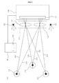
- FIG.1 is a schematic diagram of a tracking system according to an embodiment of the present invention
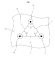
- FIG. 2 is an example diagram of markers attached on a target
- FIG. 3 is an example diagram explaining a change of image forming position when a position of the marker is changed in a same optical path as a lens.
- a tracking system includes at least three markers 110, 111 and 112, a lens array unit 120, an image forming unit 130, and a processor 140, herein, the lens array unit 120 may be included and installed on the image forming unit 130.
- the at least three markers 110, 111 and 112 are attached on the target 200 such as a lesion or a surgical instrument.
- the at least three markers 110, 111 and 112 are separated at an interval each other, the adjacent markers 110, 111 and 112 are arranged on the target 200 such as the lesion or the surgical instrument to form specific angles A1, A2 and A3 formed by a pair of straight lines L1, L2 and L3 in which the adjacent markers are virtually connected to each other.
- geometric information between the markers 110, 111 and 112 adjacent to each other in other words, length information of straight lines L1, L2 and L3 which connect the markers 110, 111 and 112 adjacent to each other and angle information A1, A2 and A3 formed by a pair of straight lines connecting the adjacent markers, are stored in a memory 141 of the processor 140.
- the markers 110, 111 and 112 may be attached on the target 200 such as a lesion and a surgical instrument in a triangle shape, length information of straight lines L1, L2 and L3 forming sides of the triangle in which the markers are used as vertices and, angle information A1, A2 and A3 formed by a pair of straight lines connecting the adjacent markers may be pre-stored in the memory 141 included in the processor 140.
- the markers 110, 111 and 112 may be active markers which self-emit lights. As described above, a light source is not needed when active markers are used as the markers 110, 111 and 112.
- the markers 110, 111 and 112 may be passive markers which reflect light emitted from at least one light source 150.
- At least one light source 150 may be arranged close to the lens array unit 120 when passive markers are used for the markers 110, 111 and 112.
- a pair of light source 150 may be arranged on both sides of the lens array unit 120.
- a spatial position and a direction of the light source 150 are pre-stored the memory 141 which is integrated in the processor 140.
- the lens array unit 120 is arranged on a front side of the image forming unit 130. At least a pair of lenses 121 and 122 are arranged and formed on such a lens array unit 120 at an interval to pass the lights emitted from the markers 110, 111 and 112. For example, the first lens 121 and the second lens 122 may be arranged and formed on the lens array unit 120 at an interval. Although the first and second lenses 121 and 122 are arranged on the lens array unit 120 at an interval as shown in the figure, however, more than three lenses may be formed at an interval on the lens array unit 120.
- the image forming unit 130 receives lights which are emitted from the markers 110, 111 and 112 and have passed each lens of the lens array unit 120, and forms images corresponding to the number of the lenses of lens array unit 120 for each marker.
- the image forming unit 130 receives the lights that are emitted from the markers 110, 111 and 112 and having passed the first and second lenses 121 and 122, and forms pair of images for each marker.
- the image forming unit 130 which receives lights that are emitted from the markers 110, 111 and 112 and have passed each lens of the lens array unit 120 and forms number of images corresponding to the number of the lenses of lens array unit 120 for each marker, may be a camera in which an image sensor 131 is integrated in it.
- the processor 140 calculates three-dimensional coordinates of the markers 110, 111 and 112 by using the images corresponding to the number of the lenses of the lens array unit for each, and calculates a spatial position and a direction of the target 200 such as a lesion or surgical instrument by comparing the three-dimensional coordinates of the markers 110, 111 and 112 with the pre-stored geometric information of the adjacent markers 110, 111 and 112.
- the memory 141 is integrated in the processor 140. Meanwhile, geometric information between the markers adjacent to each other, in other words, length information of straight lines L1, L2 and L3 which connect the marker adjacent to each other and angle information A1, A2 and A3 formed by the pair of straight lines connecting the markers 110, 111 and 112 adjacent to each other, may be pre-stored the memory 141 integrated in the processor 140.
- a spatial position and a direction of the pair of light sources 150 may be pre-stored in the memory 141 integrated in the processor 140.
- the lens array unit 120 using at least a pair of lenses 121 and 122 are arranged at an interval is used to pass lights emitted from the markers 110, 111 and 112, the lights emitted from the markers 110, 111 and 112 pass through at least a pair of lenses 121 and 122, at least a pair of images are formed on the image forming unit 120 for each marker, and therefore, there is an advantage of calculating a three-dimensional coordinates for each marker by using only one image forming unit 130.
- FIGS. 1 to 7 a tracking process of a spatial position and a direction of a target using a tracking system according to an embodiment of the present invention is described below.
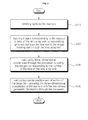
- FIG. 4 is a block diagram explaining a tracking method according to an embodiment of the present invention
- FIG. 5 is a block diagram explaining a method of calculating three-dimensional coordinates
- FIG. 6 is an example diagram of an image sensor of the image forming unit in which a coordinate of a first marker and coordinate of a second marker are virtually divided
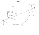
- FIG. 7 is a diagram explaining a relationship between two-dimensional coordinates and three-dimensional coordinates of a real marker.
- At least three markers 110, 111 and 112 attached on the target 200 are activated making the markers 110, 111 and 112 to emit light, or, at least one light source 150 is activated to irradiated light toward the markers 110, 111 and 112 attached on the target 200 such that the lights are reflected by the markers 110, 111 and 112 (S110).
- the markers 110, 111 and 112 are activated to emit lights.
- the markers 110, 111 and 112 are activated to emit lights.
- at least three passive (non-self-luminous) markers 110, 111 and 112 are attached on the target 200, at least one light source 150 is activated to irradiate light toward the passive markers 110, 111 and 112 attached on the target 200 such that the lights are reflected by the passive markers 110, 111 and 112.
- the lights emitted from the at least three markers 110, 111 and 112 pass through each lenses 121 and 122 of the lens array unit 120, and images corresponding to the number of the lenses of the lens array unit 120 are formed on the image forming unit 130 (S120).
- a lens array unit 120 including a pair of first and second lenses 121 and 122 and arranged at an interval when a lens array unit 120 including a pair of first and second lenses 121 and 122 and arranged at an interval is used, light emitted from the first marker 110 passes each of the first lens 121 and second lens 122 through a first optical axis AX1 and second optical axis AX2 and an image of the first marker is formed on the image forming unit 130, light emitted from the second marker 111 passes each of the first lens 121 and second lens 122 through a third optical axis AX3 and fourth optical axis AX4 and an image of the second marker is formed on the image forming unit 130, and light emitted from the third marker 112 passes each of the first lens 121 and second lens 122 through a fifth optical axis AX5 and sixth optical axis AX6 and an image of the third marker is formed on the image forming unit 130.
- a pair of images are formed on the image forming unit 130 for each marker 110, 111 and 112 by using the lens array unit 120 including a pair of first and second lenses 121 and 122 arranged at an interval.
- FIG. 5 shows a detailed process of calculating three-dimensional coordinates for each marker 110, 111 and 112.
- the lens array unit 120 in which the first and second lenses 121 and 122 are arranged at an interval.
- a camera calibration of the image forming unit 130 is processed for each coordinates (FOV(field of view) of image of the first lens and FOV of image of the second lens) (S 132).
- three-dimensional coordinates of each of the markers 110, 111 and 112 are calculated by using the two-dimensional coordinates of the pair of images formed for each marker 110, 111 and 112 (S133).
- one side of the image sensor 133 is virtually divided in a FOV (field of view) of the image of the first lens and another side of the image sensor is virtually divided in a FOV (field of view) of the image of the second lens
- two-dimensional coordinates of the direct image of the image sensor 133 are represented by a coordinate system (U,V)
- two-dimensional coordinates of the reflected image of the image sensor 133 are represented by a coordinate system (U',V').
- a relationship between the 2-dimensional coordinates of the markers 110, 111 and 112 in real space and the three-dimensional coordinates of the markers 110, 111 and 112 in real space may be represented in a formula below.
- m is two dimensional coordinates of the markers in the image
- M is three-dimensional coordinates of the markers in real space
- A(R, t) is a matrix of the camera.
- P 1 is a camera matrix of the direct image
- P 2 is a camera matrix of the reflected image
- P jT is a row vector of the matrix P.
- W may be a scale factor
- Three-dimensional coordinates of the markers 110, 111 and 112 are obtained by calculating X, Y, and Z through solving the linear equation represented in formula 4.
- geometric information between the adjacent markers 110, 111 and 112 may be length information of straight lines L1, L2 and L3 which connect the marker adjacent to each other and angle information A1, A2 and A3 formed by the pair of straight lines connecting the markers 110, 111 and 112 adjacent to each other.
- a spatial position and a direction of the target in which the markers 110, 111 and 112 are attached are calculated by comparing the three-dimensional coordinates of the markers 110, 111 and 112 in real space with pre-stored length information of straight lines L1, L2 and L3 which connect the marker adjacent to each other and pre-stored angle information A1, A2 and A3 formed by the pair of straight lines connecting the markers 110, 111 and 112 adjacent to each other.
- the lights emitted from each marker 110, 111 and 112 pass to an image forming unit 130 including at least a pair of lenses, and images corresponding to the number of the lenses of the lens array unit 130 for each marker are formed on the image forming unit 130.
- one image forming unit 130 is used to calculate a spatial position and a direction of the markers 110, 111 and 120 attached on the target 200.
Landscapes
- Health & Medical Sciences (AREA)
- Life Sciences & Earth Sciences (AREA)
- Surgery (AREA)
- Engineering & Computer Science (AREA)
- General Health & Medical Sciences (AREA)
- Heart & Thoracic Surgery (AREA)
- Veterinary Medicine (AREA)
- Public Health (AREA)
- Nuclear Medicine, Radiotherapy & Molecular Imaging (AREA)
- Animal Behavior & Ethology (AREA)
- Biomedical Technology (AREA)
- Molecular Biology (AREA)
- Medical Informatics (AREA)
- Robotics (AREA)
- Optics & Photonics (AREA)
- Biophysics (AREA)
- Physics & Mathematics (AREA)
- Radiology & Medical Imaging (AREA)
- Pathology (AREA)
- Length Measuring Devices By Optical Means (AREA)
Abstract
Description
- Exemplary embodiments of the present invention relate to a tracking system and tracking method using the same. More particularly, exemplary embodiments of the present invention relate to a tracking system and tracking method using the same for surgery capable of detecting spatial and direction information of a target by tracking coordinates of markers attached on the target such as a surgical instrument of an affected area.
- Recently, a robot surgery have been studied and introduced to reduce pain of patients and to recover faster in an endoscopic surgery or an otolaryngology surgery (ENT surgery).
- In such a robot surgery, in order to minimize risk of the surgery and to operate the surgery more precisely, a navigation system is used to navigate to an exact lesion of a patient by tracking and detecting a spatial position and a direction of a target such as lesion portion or surgical instrument.
- The navigation system described above includes a tracking system which is capable of tracking and detecting a spatial position and a direction of a target such as lesion or surgical instrument.
- The tracking system described above includes a plurality of markers attached on a lesion or a surgical instrument, a first and second image forming units forming images of lights emitted from the markers, and a processor calculating three-dimensional coordinates of the markers which are connected to the first and second image forming units and calculating a spatial position and a direction of the target by comparing pre-stored information of straight lines which connect the markers adjacent to each other and, angle information which are formed by a pair of straight lines adjacent to each other with the three-dimensional coordinates of the markers.
- Herein, in order to calculate the three-dimensional coordinates of the markers, conventionally, two detectors are required to calculate the three-dimensional coordinates of each marker through a processor, a trigonometry is used in an assumption that a coordinate of marker which is emitted from one marker and forming image on a first image forming unit and a coordinate of marker which is emitted from one marker and forming image on a second image forming unit are identical.
- Conventional tracking system requires two image forming units to form images of lights which are emitted from each marker in different position to each other, manufacturing cost increases as well as a whole size also increases, therefore, a restriction of a surgical space is generated.
- Therefore, the technical problem of the present invention is to provide a tracking system and method using the same capable of reducing manufacturing cost as well as minimizing restriction of a surgical space by achieving compact of the system through calculating three-dimensional coordinates of each of markers by using only one image forming unit.
- In one embodiment of the present invention, a tracking system includes at least three markers which are attached on a target and emit lights or reflect lights emitted from a light source, a lens array unit in which at least two lenses are arranged at an interval to pass the lights emitted from the markers, an image forming unit which receives the lights that are emitted from the markers and have passed the lens array and forms images corresponding to the number of the lenses of the lens array unit, and a processor which calculates a three-dimensional coordinates of each marker using the images corresponding to the number of the lenses of lens array unit, compares the three-dimensional coordinates of the markers with pre-stored geometric information of markers which are adjacent to each other, and calculates a spatial position and direction of the target.
- In one embodiment, the markers may be self-luminous active markers.
- Meanwhile, the tracking system may further include at least one light source emitting light from the lens array unit to the markers, in this case, the markers may be passive markers which reflect light from the light source to the lens array unit.
- In one embodiment, the image forming unit may be a camera which receives lights that are emitted from the markers and have passed each lens of the lens array unit, and forms at least two images corresponding to the number of the lenses of the lens array unit for each marker.
- In one embodiment, geometric information of the markers may be length information connecting markers adjacent to each other and angle information formed by a pair of straight lines adjacent to each other.
- In one embodiment of the present invention, a tracking method includes emitting lights by at least three markers attached on a target, forming images corresponding to the number of the lenses of lens array unit, in which the lens array unit includes at least two lenses and lights emitted from the markers pass through them, calculating three-dimensional coordinates for each marker by using the images that are formed on the image forming unit corresponding to the number of the lenses of lens array unit for each marker through the processor and, calculating a spatial position and a direction of the target by comparing the three-dimensional coordinates of the each marker with pre-stored geometric information of markers adjacent to each other.
- In some embodiment, geometric information of the markers may be length information connecting markers adjacent to each other, and angle information formed by a pair of straight lines adjacent to each other.
- Meanwhile, the process of calculating three-dimensional coordinates of the marker may include calculating two-dimensional coordinates of the images corresponding to the number of the lenses of lens array unit formed on the image forming unit for each marker through the processor and, calculating three-dimensional coordinates of the markers by using the two-dimensional coordinates of the images corresponding to the number of the lenses of lens array unit for each marker.
- In some embodiment, the process of emitting lights by the markers, markers may self-emit lights to the lens array unit.
- Alternatively, the process of emitting lights by the markers, at least a light source is used to emit light, and the light is reflected from the lens array unit through the markers.
- Meanwhile, a spatial position and a direction of the light source are pre-stored in the processor.
- Thus, according to an embodiment of the present invention, in a tracking system and tracking method using the same, lights emitted from each marker pass through a lens array unit which includes at least a pair of lens, images corresponding to the number of the lenses of lens array units are formed on an image forming for each marker, and therefore, it is possible to calculate a spatial position and a direction of the markers attached on the target by using only one image forming unit through a trigonometry.
- Also, since the system is not affected by lens array method and magnification, there is an effect of reducing manufacturing cost of the tracking system, making small and lightweight, and relatively low restriction of a surgical space compared with the conventional tracking system.
-
-
FIG.1 is a schematic diagram of a tracking system according to an embodiment of the present invention. -
FIG. 2 is an example diagram of markers attached on a target. -
FIG. 3 is an example diagram explaining a change of image forming position of a marker when a position of the marker is changed in a same optical path as a lens. -
FIG. 4 is a block diagram explaining a tracking method according to an embodiment of the present invention. -
FIG. 5 is a block diagram explaining a method of calculating three-dimensional coordinates. -
FIG. 6 is an example diagram of an image sensor of the image forming unit in which a coordinate of a first marker and a coordinate of a second marker are virtually divided. -
FIG. 7 is a diagram explaining a relationship between two-dimensional coordinates and three-dimensional coordinates of a real marker. - The present invention is described more fully hereinafter with reference to the accompanying drawings, in which example embodiments of the present invention are shown. The present invention may, however, be embodied in many different forms and should not be construed as limited to the example embodiments set forth herein. Rather, these example embodiments are provided so that this disclosure will be thorough and complete, and will fully convey the scope of the present invention to those skilled in the art. In the drawings, the sizes and relative sizes of layers and regions may be exaggerated for clarity.
- It will be understood that, although the terms first, second, third, etc. may be used herein to describe various elements, components, regions, layers and/or sections, these elements, components, and/or sections should not be limited by these terms. These terms are only used to distinguish one element, component, region, layer or section from another region, layer or section. Thus, a first element, component, or section discussed below could be termed a second element, component, or section without departing from the teachings of the present invention.
- The terminology used herein is for the purpose of describing particular example embodiments only and is not intended to be limiting of the present invention. As used herein, the singular forms "a," "an" and "the" are intended to include the plural forms as well, unless the context clearly indicates otherwise. It will be further understood that the terms "comprises" and/or "comprising," when used in this specification, specify the presence of stated features, integers, steps, operations, elements, and/or components, but do not preclude the presence or addition of one or more other features, integers, steps, operations, elements, components, and/or groups thereof.
- Unless otherwise defined, all terms (including technical and scientific terms) used herein have the same meaning as commonly understood by one of ordinary skill in the art to which this invention belongs. It will be further understood that terms, such as those defined in commonly used dictionaries, should be interpreted as having a meaning that is consistent with their meaning in the context of the relevant art and will not be interpreted in an idealized or overly formal sense unless expressly so defined herein.
- Hereinafter, with reference to the drawings, preferred embodiments of the present invention will be described in detail.
- In a tracking system and method using the same according to an embodiment of the present invention, at least three markers are attached on a patient or a surgical instrument, three-dimensional coordinates of the markers are calculated, the three-dimensional coordinates of the markers are compared with pre-stored geometric information of markers adjacent to each other through a processor, and therefore, it is capable of calculating a spatial position and a direction of a target such as a lesion or surgical instrument. The detailed description is explained referencing figures.
-
FIG.1 is a schematic diagram of a tracking system according to an embodiment of the present invention,FIG. 2 is an example diagram of markers attached on a target, andFIG. 3 is an example diagram explaining a change of image forming position when a position of the marker is changed in a same optical path as a lens. - Referring to
FIGS. 1 to 3 , a tracking system according to an embodiment of the present invention includes at least threemarkers lens array unit 120, animage forming unit 130, and aprocessor 140, herein, thelens array unit 120 may be included and installed on theimage forming unit 130. - The at least three
markers target 200 such as a lesion or a surgical instrument. Herein, the at least threemarkers adjacent markers target 200 such as the lesion or the surgical instrument to form specific angles A1, A2 and A3 formed by a pair of straight lines L1, L2 and L3 in which the adjacent markers are virtually connected to each other. - Herein, geometric information between the
markers markers memory 141 of theprocessor 140. - For example, the
markers target 200 such as a lesion and a surgical instrument in a triangle shape, length information of straight lines L1, L2 and L3 forming sides of the triangle in which the markers are used as vertices and, angle information A1, A2 and A3 formed by a pair of straight lines connecting the adjacent markers may be pre-stored in thememory 141 included in theprocessor 140. - Meanwhile, the
markers markers - Alternatively, the
markers light source 150. - As described above, at least one
light source 150 may be arranged close to thelens array unit 120 when passive markers are used for themarkers light source 150 may be arranged on both sides of thelens array unit 120. Herein, a spatial position and a direction of thelight source 150 are pre-stored thememory 141 which is integrated in theprocessor 140. - The
lens array unit 120 is arranged on a front side of theimage forming unit 130. At least a pair oflenses lens array unit 120 at an interval to pass the lights emitted from themarkers first lens 121 and thesecond lens 122 may be arranged and formed on thelens array unit 120 at an interval. Although the first andsecond lenses lens array unit 120 at an interval as shown in the figure, however, more than three lenses may be formed at an interval on thelens array unit 120. - The
image forming unit 130 receives lights which are emitted from themarkers lens array unit 120, and forms images corresponding to the number of the lenses oflens array unit 120 for each marker. - In more detail, when the first and
second lenses lens array unit 120 at an interval, theimage forming unit 130 receives the lights that are emitted from themarkers second lenses - For example, the
image forming unit 130, which receives lights that are emitted from themarkers lens array unit 120 and forms number of images corresponding to the number of the lenses oflens array unit 120 for each marker, may be a camera in which animage sensor 131 is integrated in it. Theprocessor 140 calculates three-dimensional coordinates of themarkers target 200 such as a lesion or surgical instrument by comparing the three-dimensional coordinates of themarkers adjacent markers - Herein, the
memory 141 is integrated in theprocessor 140. Meanwhile, geometric information between the markers adjacent to each other, in other words, length information of straight lines L1, L2 and L3 which connect the marker adjacent to each other and angle information A1, A2 and A3 formed by the pair of straight lines connecting themarkers memory 141 integrated in theprocessor 140. - Additionally, when the
markers light sources 150 may be pre-stored in thememory 141 integrated in theprocessor 140. - As described above, in the
tracking system 100 according to an embodiment of the present invention, thelens array unit 120 using at least a pair oflenses markers markers lenses image forming unit 120 for each marker, and therefore, there is an advantage of calculating a three-dimensional coordinates for each marker by using only oneimage forming unit 130. - For example, as shown in
FIG. 3 , when a position of themarkers image sensor 133, in which an image of thesecond lens 122 is formed, is not changed, however, a position of theimage sensor 133, in which an image of thefirst lens 121 is formed, is changed, therefore, it is possible to calculate a three-dimensional coordinates for each marker by using only oneimage forming unit 130 through a trigonometry. - Referring to
FIGS. 1 to 7 , a tracking process of a spatial position and a direction of a target using a tracking system according to an embodiment of the present invention is described below. -
FIG. 4 is a block diagram explaining a tracking method according to an embodiment of the present invention,FIG. 5 is a block diagram explaining a method of calculating three-dimensional coordinates,FIG. 6 is an example diagram of an image sensor of the image forming unit in which a coordinate of a first marker and coordinate of a second marker are virtually divided, andFIG. 7 is a diagram explaining a relationship between two-dimensional coordinates and three-dimensional coordinates of a real marker. - Referring to
FIGS. 1 to 7 , in order to track a spatial position and direction of atarget 200 using a tracking system according to an embodiment of the present invention, first, at least threemarkers target 200 are activated making themarkers light source 150 is activated to irradiated light toward themarkers target 200 such that the lights are reflected by themarkers - In more detail, when at least three active (self-luminous)
markers target 200, themarkers markers target 200, at least onelight source 150 is activated to irradiate light toward thepassive markers target 200 such that the lights are reflected by thepassive markers - The lights emitted from the at least three
markers lenses lens array unit 120, and images corresponding to the number of the lenses of thelens array unit 120 are formed on the image forming unit 130 (S120). - For example, as shown in
FIG. 1 , when alens array unit 120 including a pair of first andsecond lenses first marker 110 passes each of thefirst lens 121 andsecond lens 122 through a first optical axis AX1 and second optical axis AX2 and an image of the first marker is formed on theimage forming unit 130, light emitted from thesecond marker 111 passes each of thefirst lens 121 andsecond lens 122 through a third optical axis AX3 and fourth optical axis AX4 and an image of the second marker is formed on theimage forming unit 130, and light emitted from thethird marker 112 passes each of thefirst lens 121 andsecond lens 122 through a fifth optical axis AX5 and sixth optical axis AX6 and an image of the third marker is formed on theimage forming unit 130. - In other words, a pair of images are formed on the
image forming unit 130 for eachmarker lens array unit 120 including a pair of first andsecond lenses - When images corresponding to the number of the lenses of lens array unit are formed on the
image forming unit 130 for eachmarker marker image forming unit 130 for eachmarker -
FIG. 5 shows a detailed process of calculating three-dimensional coordinates for eachmarker lens array unit 120 in which the first andsecond lenses - In order to calculate three-dimensinal coordinates of the
markers image forming unit 130 for eachmarker - Herein, after calculating two-dimensional coordinates of the
markers image forming unit 130 is processed for each coordinates (FOV(field of view) of image of the first lens and FOV of image of the second lens) (S 132). - As described above, after processing a camera calibration, three-dimensional coordinates of each of the
markers marker - Referring to
FIGS. 6 and7 , a detailed process of calculating three-dimensional coordinates of each of themarkers - As shown in
FIG. 6 , one side of theimage sensor 133 is virtually divided in a FOV (field of view) of the image of the first lens and another side of the image sensor is virtually divided in a FOV (field of view) of the image of the second lens, two-dimensional coordinates of the direct image of theimage sensor 133 are represented by a coordinate system (U,V), and two-dimensional coordinates of the reflected image of theimage sensor 133 are represented by a coordinate system (U',V'). Referring toFIG. 7 , a relationship between the 2-dimensional coordinates of themarkers markers 
- Herein, m is two dimensional coordinates of the markers in the image, M is three-dimensional coordinates of the markers in real space, and A(R, t) is a matrix of the camera.
- In order to explain more briefly, when three-dimensional coordinates of
real markers real markers real markers 
- Herein, P1 is a camera matrix of the direct image, and P2 is a camera matrix of the reflected image.
- And, relation formulas of the direct image and reflected image of each of the
markers 
- Herein, PjT is a row vector of the matrix P.
- The formula 3 may be represented in Formula 4.

- Herein, W may be a scale factor.
- Three-dimensional coordinates of the
markers - As described in
FIGS. 4 and5 , after calculating three-dimensional coordinates of eachmarker processor 140, three-dimensional coordinates of themarkers processor 140, and a spatial position and a direction of themarkers target 200 are calculated (S140). - Herein, as described above, geometric information between the
adjacent markers markers - In other words, a spatial position and a direction of the target in which the
markers markers markers - As described above, a tracking system and method using the same according to an embodiment of the present invention, the lights emitted from each
marker image forming unit 130 including at least a pair of lenses, and images corresponding to the number of the lenses of thelens array unit 130 for each marker are formed on theimage forming unit 130. - In other words, when a
lens array unit 120 including a pair of first andsecond lenses image forming unit 130 through two optical axis for each marker, and therefore, three-dimensional coordinates of the markers are calculated by using only oneimage forming unit 130 through a trigonometry. - Therefore, a tracking system and method using the same according to an embodiment of the present invention, one
image forming unit 130 is used to calculate a spatial position and a direction of themarkers target 200. - Therefore, there is an effect of reducing a manufacturing cost of the tracking system, making small and lightweight, and relatively low restriction of surgical space compared with the conventional tracking system.
- It will be apparent to those skilled in the art that various modifications and variation can be made in the present invention without departing from the scope of the invention. Thus, it is intended that the present invention cover the modifications and variations of this invention provided they come within the scope of the appended claims and their equivalents.
Claims (11)
- A tracking system comprising:at least three markers attached on a target to emit lights;a lens array unit including at least two lenses arranged at an interval to pass the lights emitted from the markers;an image forming unit receiving the lights that are emitted from the markers and have passed through each lens of the lens array unit, and forming images corresponding to the number of the lenses of the lens array unit for each marker; anda processor calculating three-dimensional coordinates of the markers by using the images of the markers that are formed on the image forming unit corresponding to the number of the lenses of the lens array unit for each marker, and calculating a spatial position and a direction of the target by comparing the three-dimensional coordinates of the markers with pre-stored geometric information between the markers adjacent to each other.
- The tracking system of claim 1, wherein the markers are self-luminous active markers.
- The tracking system of claim 1, further comprising at least one light source emitting light from the lens array unit toward the markers, wherein the markers are passive markers reflecting the emitted light from the light source toward the lens array unit.
- The tracking system of claim 1, wherein the image forming unit is a camera forming at least two images corresponding to the number of the lens of lens array unit for each marker by receiving lights emitted from the markers and having passed through each lens of the lens array unit.
- The tracking system of claim 1, wherein the geometric information between the markers comprises length information of straight lines which connect the markers adjacent to each other, and angle information which is formed by a pair of straight lines adjacent to each other.
- A tracking method comprising:emitting lights by at least three markers attached on a target;forming images corresponding to the number of the lenses of a lens array unit formed on an image forming unit, wherein the images are formed by the lights emitted from the markers and having passed through the at least two lenses of the lens array unit;calculating three-dimensional coordinates for each marker through a processor by using the images of the markers formed on the image forming unit corresponding to the number of the lenses of the lens array unit; andcalculating a spatial position and a direction of the target by comparing the three-dimensional coordinates of each marker with geometric information between the markers adjacent to each other, wherein the geometric information is pre-stored in a processor.
- The tracking method of claim 6, wherein the geometric information comprises length information of straight lines which connect the markers adjacent to each other and, angle information which are formed by a pair of straight lines adjacent to each other.
- The tracking method of claim 6, wherein calculating the three-dimensional coordinates of the markers comprises:calculating two-dimensional coordinates of the images of the markers corresponding to the number of the lenses of the lens array unit formed on the image forming unit for each marker through the processor; andcalculating the three-dimensional coordinates of the markers through the processor by using the two-dimensional coordinates of the images of the markers corresponding to the number of the lenses of the lens array unit for each marker.
- The tracking method of claim 6, wherein in emitting lights by the markers, the markers self-emit light toward the lens array unit.
- The tracking method of claim 6, wherein in emitting lights by the markers, light emitted from at least one light source is reflected to the lens array unit through the markers.
- The tracking method of claim 10, wherein a spatial position and a direction of the light source are pre-stored in the processor.
Applications Claiming Priority (2)
| Application Number | Priority Date | Filing Date | Title |
|---|---|---|---|
| KR1020130005807A KR101371387B1 (en) | 2013-01-18 | 2013-01-18 | Tracking system and method for tracking using the same |
| PCT/KR2014/000426 WO2014112782A1 (en) | 2013-01-18 | 2014-01-15 | Tracking system and tracking method using same |
Publications (2)
| Publication Number | Publication Date |
|---|---|
| EP2946741A1 true EP2946741A1 (en) | 2015-11-25 |
| EP2946741A4 EP2946741A4 (en) | 2016-09-07 |
Family
ID=50647855
Family Applications (1)
| Application Number | Title | Priority Date | Filing Date |
|---|---|---|---|
| EP14740207.7A Withdrawn EP2946741A4 (en) | 2013-01-18 | 2014-01-15 | TRACKING SYSTEM AND TRACKING METHOD USING THE SAME |
Country Status (6)
| Country | Link |
|---|---|
| US (1) | US20160270860A1 (en) |
| EP (1) | EP2946741A4 (en) |
| JP (1) | JP2016515837A (en) |
| KR (1) | KR101371387B1 (en) |
| CN (1) | CN104936547A (en) |
| WO (1) | WO2014112782A1 (en) |
Families Citing this family (7)
| Publication number | Priority date | Publication date | Assignee | Title |
|---|---|---|---|---|
| CN105809654B (en) * | 2014-12-29 | 2018-11-23 | 深圳超多维科技有限公司 | Target object tracking, device and stereoscopic display device and method |
| CN105812775A (en) * | 2014-12-29 | 2016-07-27 | 广东省明医医疗慈善基金会 | Three-dimensional display system based on hard lens and method thereof |
| CN105812772B (en) * | 2014-12-29 | 2019-06-18 | 深圳超多维科技有限公司 | Medical image stereoscopic display system and method |
| CN105812776A (en) * | 2014-12-29 | 2016-07-27 | 广东省明医医疗慈善基金会 | Stereoscopic display system based on soft lens and method |
| CN105812774B (en) * | 2014-12-29 | 2019-05-21 | 广东省明医医疗慈善基金会 | Three-dimensional display system and method based on intubation mirror |
| CN105791800B (en) * | 2014-12-29 | 2019-09-10 | 深圳超多维科技有限公司 | Three-dimensional display system and stereo display method |
| CN115023170B (en) * | 2020-01-16 | 2026-04-10 | 奥林巴斯株式会社 | Endoscopic system, control device and information processing method |
Family Cites Families (15)
| Publication number | Priority date | Publication date | Assignee | Title |
|---|---|---|---|---|
| US4396945A (en) * | 1981-08-19 | 1983-08-02 | Solid Photography Inc. | Method of sensing the position and orientation of elements in space |
| US5923417A (en) * | 1997-09-26 | 1999-07-13 | Northern Digital Incorporated | System for determining the spatial position of a target |
| US6061644A (en) * | 1997-12-05 | 2000-05-09 | Northern Digital Incorporated | System for determining the spatial position and orientation of a body |
| US6279579B1 (en) | 1998-10-23 | 2001-08-28 | Varian Medical Systems, Inc. | Method and system for positioning patients for medical treatment procedures |
| WO2002061371A1 (en) * | 2001-01-30 | 2002-08-08 | Z-Kat, Inc. | Tool calibrator and tracker system |
| US20110015521A1 (en) * | 2003-03-27 | 2011-01-20 | Boulder Innovation Group, Inc. | Means of Tracking Movement of Bodies During Medical Treatment |
| WO2005000139A1 (en) * | 2003-04-28 | 2005-01-06 | Bracco Imaging Spa | Surgical navigation imaging system |
| US8211094B2 (en) * | 2004-10-26 | 2012-07-03 | Brainlab Ag | Pre-calibrated reusable instrument |
| US9867669B2 (en) * | 2008-12-31 | 2018-01-16 | Intuitive Surgical Operations, Inc. | Configuration marker design and detection for instrument tracking |
| KR100669250B1 (en) | 2005-10-31 | 2007-01-16 | 한국전자통신연구원 | Artificial Marker-based Real-time Positioning System and Method |
| JP4459155B2 (en) * | 2005-11-14 | 2010-04-28 | 株式会社東芝 | Optical position measuring device |
| DE112007000340T5 (en) * | 2006-02-09 | 2008-12-18 | Northern Digital Inc., Waterloo | Retroreflective brand tracking systems |
| EP1872735B1 (en) * | 2006-06-23 | 2016-05-18 | Brainlab AG | Method for automatic identification of instruments during medical navigation |
| KR101136743B1 (en) | 2011-04-27 | 2012-04-19 | 목포대학교산학협력단 | Position measuring device having distance and angle measuring function |
| KR101371384B1 (en) * | 2013-01-10 | 2014-03-07 | 경북대학교 산학협력단 | Tracking system and method for tracking using the same |
-
2013
- 2013-01-18 KR KR1020130005807A patent/KR101371387B1/en active Active
-
2014
- 2014-01-15 EP EP14740207.7A patent/EP2946741A4/en not_active Withdrawn
- 2014-01-15 US US14/372,307 patent/US20160270860A1/en not_active Abandoned
- 2014-01-15 JP JP2015553651A patent/JP2016515837A/en active Pending
- 2014-01-15 WO PCT/KR2014/000426 patent/WO2014112782A1/en not_active Ceased
- 2014-01-15 CN CN201480004953.3A patent/CN104936547A/en active Pending
Also Published As
| Publication number | Publication date |
|---|---|
| US20160270860A1 (en) | 2016-09-22 |
| WO2014112782A1 (en) | 2014-07-24 |
| KR101371387B1 (en) | 2014-03-10 |
| JP2016515837A (en) | 2016-06-02 |
| CN104936547A (en) | 2015-09-23 |
| EP2946741A4 (en) | 2016-09-07 |
Similar Documents
| Publication | Publication Date | Title |
|---|---|---|
| US20160270860A1 (en) | Tracking system and tracking method using the same | |
| US11883105B2 (en) | Surgical navigation system using image segmentation | |
| US8885177B2 (en) | Medical wide field of view optical tracking system | |
| US12551289B2 (en) | Tracker-based surgical navigation | |
| EP3281599B1 (en) | Marker for optical tracking, optical tracking system, and optical tracking method | |
| US20250345129A1 (en) | Optical tracking system and tracking method using the same | |
| US20170069073A1 (en) | System and method detecting and adjusting for reference marker errors in surgical navigation systems | |
| JP2011504769A (en) | Optical tracking CAS system | |
| EP2944285B1 (en) | Tracking system and method for tracking by using same | |
| EP2959857A1 (en) | Tracking system and tracking method using same | |
| CN115670651B (en) | Methods and systems for determining the relative position of at least one object in an operating room | |
| EP1923756A1 (en) | Method and system for region of interest calibration parameter adjustment of tracking systems | |
| US8175675B2 (en) | Deformable marker device | |
| US20260137461A1 (en) | Tracker-Based Surgical Navigation | |
| EP3644845B1 (en) | Position detection system by fiber bragg grating based optical sensors in surgical fields | |
| US20260099942A1 (en) | Optical Tracker Configured To Emit Or Reflect Polarized Light |
Legal Events
| Date | Code | Title | Description |
|---|---|---|---|
| PUAI | Public reference made under article 153(3) epc to a published international application that has entered the european phase |
Free format text: ORIGINAL CODE: 0009012 |
|
| 17P | Request for examination filed |
Effective date: 20150729 |
|
| AK | Designated contracting states |
Kind code of ref document: A1 Designated state(s): AL AT BE BG CH CY CZ DE DK EE ES FI FR GB GR HR HU IE IS IT LI LT LU LV MC MK MT NL NO PL PT RO RS SE SI SK SM TR |
|
| AX | Request for extension of the european patent |
Extension state: BA ME |
|
| DAX | Request for extension of the european patent (deleted) | ||
| A4 | Supplementary search report drawn up and despatched |
Effective date: 20160805 |
|
| RIC1 | Information provided on ipc code assigned before grant |
Ipc: A61B 1/313 20060101ALI20160801BHEP Ipc: A61B 34/20 20160101AFI20160801BHEP |
|
| STAA | Information on the status of an ep patent application or granted ep patent |
Free format text: STATUS: THE APPLICATION IS DEEMED TO BE WITHDRAWN |
|
| 18D | Application deemed to be withdrawn |
Effective date: 20170303 |