EP2946683A1 - Fastener element and fastener stringer - Google Patents
Fastener element and fastener stringer Download PDFInfo
- Publication number
- EP2946683A1 EP2946683A1 EP13872050.3A EP13872050A EP2946683A1 EP 2946683 A1 EP2946683 A1 EP 2946683A1 EP 13872050 A EP13872050 A EP 13872050A EP 2946683 A1 EP2946683 A1 EP 2946683A1
- Authority
- EP
- European Patent Office
- Prior art keywords
- fastener
- portions
- tape
- main surface
- thinning
- Prior art date
- Legal status (The legal status is an assumption and is not a legal conclusion. Google has not performed a legal analysis and makes no representation as to the accuracy of the status listed.)
- Granted
Links
Images





Classifications
-
- A—HUMAN NECESSITIES
- A44—HABERDASHERY; JEWELLERY
- A44B—BUTTONS, PINS, BUCKLES, SLIDE FASTENERS, OR THE LIKE
- A44B19/00—Slide fasteners
- A44B19/02—Slide fasteners with a series of separate interlocking members secured to each stringer tape
Definitions
- the present invention relates to a metal fastener element for a slide fastener, and in particular, to a metal fastener element, in which even if a slide fastener is constructed so that an attachment pitch thereof to a fastener tape is small, reduction in pliability of a fastener stringer or reduction in sliding ability of a slider can be inhibited.
- a fastener element made of metal includes an engaging head portion, a body portion extending from the engaging head portion in one direction (rearward), and a pair of right and left leg portions extending to be bifurcated from the body portion in one direction (rearward).
- the engaging head portion is provided with an engaging protrusion portion and an engaging concave portion or fitting space portion configured to allow an engaging protrusion portion of the counterpart fastener element to be fitted therein.
- a fastener element of a single side type (hereinafter, simply referred to as a single side element), in which an engaging protrusion portion is provided on one surface (upper surface) of an engaging head portion and an engaging concave portion is provided on the other surface (lower surface) of the engaging head portion
- a fastener element of a double side type (hereinafter, simply referred to as a double side element), in which an engaging protrusion portion and a fitting space portion are provided in one set on each of both upper and lower surface of an engaging head portion, are known.
- Patent Document 1 a single side element disclosed in Japanese Utility Model Examined Publication No. S50-10889 (Patent Document 1) will be described.
- the single side element described in Patent Document 1 has an engaging head portion, a body portion and a pair of right and leg portions, and an engaging protrusion portion is provided to protrude on an upper surface of the engaging head portion and an engaging concave portion is provided to be concaved on a lower surface of the engaging head portion.
- the right and left leg portions include a thick thickness portion arranged on a base end portion of each leg portion and having a predetermined thickness, and a thin thickness portion arranged on a leading end portion of each leg portion and configured to reduce a thickness of the fastener element relative to the thick thickness portion via a step.
- the thin thickness portion of the leg portions is arranged to extend from an inner peripheral edge (end edge of a tape contact side thereof) to an outer peripheral edge (end edge thereof exposed to the outside) when the fastener element is viewed from the upper side.
- the step which is a boundary between the thick thickness portion and the thin thickness portion, is arranged to be curved toward the engaging head portion as it goes from inner peripheral edges of the leg portions toward outer side edges of the fastener element. Accordingly, the thin thickness portion is arranged on the outer side edge portions of the fastener element over a wide range extending from leading ends of the leg portions to a part of the body portion.
- stiffening in the tape side edge portion of the fastener tape due to attaching of the fastener element thereto can be alleviated, thereby enhancing pliability of the fastener stringer. Also, as pliability of the fastener stringer is enhanced, sliding of a slider can be smoothly performed.
- a double side element 80 described in Patent Document 2 has an engaging head portion 81, a body portion 82 and a pair of right and left leg portions 83 and is configured so that front and back sides thereof are symmetric with respect to a center position in an element thickness direction.
- the engaging head portion 81 of Patent Document 2 has a thin plate-shaped head body (also referred to as a base portion) 81a, one set of an engaging protrusion portion 84 and a fitting space portion 85 arranged on an upper surface of the head body 81a, and one set of an engaging protrusion portion 84 and a fitting space portion 85 arranged on a lower surface of the head body 81a.
- each of the fitting space portions 85 arranged on the upper and lower surfaces according to Patent Document 2 right and left side wall portions 86 are erected from the head body 81a to be continued from the engaging protrusion portion 84, so that the respective fitting space portion 85 are surrounded at three sides by the engaging protrusion portion 84 and the right and left side wall portions 86. Also, on a rear side of the fitting space portion 85, a bottom surface 85 of the fitting space portion 85 is arranged to extend to a location of a crotch portion 87 through the body portion 82 of the fastener element 80.
- the fitting space portion 85 and the right and left side wall portions 86 are provided to continuously extend from the engaging head portion 81 toward the leg portions 83, and also, on outside of the right and left side wall portions 84, inclined portions 88 are arranged to gradually increase a thickness-direction dimension (thickness dimension) of the fastener element 80 as they go from the engaging head portion 81 toward the leg portions 83.
- the right and left leg portions 83 of Patent Document 2 have a leg portion body 83a extending from the body portion 82 and having a constant thickness dimension and a swollen portion 83b slightly swollen inward from an inner peripheral surface of the leg portion body 83a.
- the swollen portion 83b is arranged at the middle portion of the leg portions 83 in the thickness direction, and upper and lower surfaces of the swollen portion 83b are formed so as to be flushed with bottom surfaces 85a of the fitting space portions 85.
- a swollen amount (protrusion height), by which the swollen portion 83b is swollen from the inner peripheral surface of the leg portion body 83a, is set to be extremely small in an order of about one thousandth of 1 inch.
- Patent Document 2 a punching line when the fastener element 80 is punched from a rolled material by a punch and a die is set on a boundary line between the swollen portion 83b, which has a thickness thinner than the leg portion body 83a, and the head body 81a of the engaging head portion 81, and thus, as described above, the swollen portion 83b is formed on the inner peripheral surface of the leg portions 83.
- the fastener element 80 of Patent Document 2 shown in Fig. 16 is attached to a fastener tape by pressing the leg portions 83 in directions approaching each other in a state where the fastener tape is positioned between the right and left leg portions 83, and thus by crimping the fastener element 80.
- the fastener element 80 of Patent Document 2 the swollen amount, by which the swollen portion 83b is swollen from the inner peripheral surface of the leg portion body 83a, is extremely small as described above. Accordingly, when the fastener element 80 is attached to the fastener tape by crimping, the entire inner peripheral surface of the leg portion body 83a is pressed against the fastener tape by an action of elastic force of the fastener tape, and also the entire outer surface of the swollen portion 83b is pressed against the fastener tape. Accordingly, the fastener element 80 can reliably grip the fastener tape by the right and leg portions 83 and thus an attachment strength of each fastener element 80 to the fastener tape can be enhanced.
- the thin thickness portion is formed so as to extend from the inner peripheral edge to the outer side edge of the right and left leg portions. Accordingly, when the fastener element is attached to the tape side edge portion of the fastener tape, a tape contact portion (contact area) of the fastener element is small and as a result, pliability of the fastener stringer is enhanced.
- the thin thickness portion is formed so as to extend to outer side edges of the leg portions and body portion. Therefore, when the fastener elements are attached to the fastener tape to construct a slide fastener, there is a problem in that the thin thickness formed on each fastener element is exposed to the outside and thus the exterior or appearance of the slide fastener gets damaged.
- the bottom surfaces 85a of the fitting space portions 85 arranged on the element upper and lower surfaces extend to the location of the crotch portion 87 through the body portion 82 of the fastener element 80, and the middle portion of the body portion 82 following the crotch portion 87 is constructed by the thin thickness portion having a thickness dimension smaller than the leg portion body 83a.
- the middle portion of the body portion 82 constructed by the thin thickness portion does not have a high strength
- the middle portion of the body portion 82 which is formed so as to have such a thin thickness is likely to be deformed as the leg portions 83 are plastically deformed.
- an attachment position of the fastener element 80 to the fastener tape is likely to be dislocated, a posture of the fastener element 80 is likely to be inclined or the like, and thus this is considered as a cause of reducing yields in manufacturing of the slide fastener.
- the double side elements 80 have a narrower attachment pitch in a tape length direction so that the fastener tape exposed between fastener elements 80 of element rows is not hardly seen, thereby providing a slide fastener in which design ability is enhanced or luxury feeling is imparted as compared to a conventional case.
- the fastener tape in parts of the fastener tape, to which the fastener elements 80 are contacted, the fastener tape is securely gripped by the fastener elements 80. Accordingly, as the attachment pitch of the fastener element 80 becomes narrower as described above, a tape contact area of the fastener elements 80 per unit length in a tape length direction is increased so that softness or bendability of the fastener tape is eliminated. As a result, there is a harmful effect that reduction in pliability of the fastener stringer or reduction in flexibility thereof in a tape front and back direction or tape width direction is occurred.
- the fastener tape is generally tensioned in the tape length direction in order to stabilize attachment of the double side elements 80, so that an attaching operation of double side elements 80 is performed in a state where a tension in the tape length direction is applied to the fastener tape. Also, after the attaching operation of the double side element 80 is ended, the tension applied to the fastener tape is released and thus the fastener tape is shrunken in the tape length direction.
- the fastener tape is hardly shrunken in the tape length direction in the tape length direction in a tape portion, to which the double side elements 80 are attached, and thus a shrinkage amount of such an element attachment portion of the fastener tape is smaller than that of a tape main body portion of the fastener tape.
- the present invention has been made keeping in mind the above problems, and an detailed object thereof is to provide a fastener element in which pliability of a fastener stringer can be enhanced, a posture of the fastener element upon sliding of a slider can hardly be inclined in an element guide passage of the slider, and also problems, such as reduction in pliability or flexibility of the fastener stringer, reduction in sliding ability of the slider, occurrence of puckering and the like, are hardly occurred even if an attachment pitch of the fastener element in a tape length direction is narrower.
- a fastener element provided according to the present invention includes, as basic conjurations, an engaging head portion, a body portion arranged on one end of the engaging head portion, and a pair of right and left leg portions extending to be bifurcated from one end of the body portion, wherein the engaging head portion includes a flat plate-shaped head body comprising a first main surface and a second main surfaces opposite to the first main surface, engaging protrusion portions formed so as to protrude from the first main surface and the second main surface of the head body, and fitting space portions arranged between the engaging protrusion portions and the body portion on the first main surface and the second main surface and configured to allow counterpart engaging protrusion portion to be fitted therein, wherein a tape nipping surface is provided on inner peripheral surfaces of the body portion and the right and left leg portions, wherein the body portion includes a bridge portion provided between the fitting space portions and the tape nipping surface so as to be raised from a location of a bottom surface of the fitting space portion in an element thickness direction and
- a fastener element of another embodiment provided according to the present invention includes, as basic conjurations, an engaging head portion, a body portion arranged on one end of the engaging head portion, and a pair of right and left leg portions extending to be bifurcated from one end of the body portion, wherein the engaging head portion includes a head body comprising a first main surface and a second main surface opposite to the first main surface, an engaging protrusion portion formed so as to protrude from the first main surface of the head body, and an engaging concave portion provided so as to be concaved in a bottomed shape relative to the second main surface of the head body, wherein a tape nipping surface is provided on inner peripheral surfaces of the body portion and the right and left leg portions, wherein the body portion and the right and left leg portions include an inner peripheral edge portion arranged along the tape nipping surface and outer side edge portions arranged along right and left element outer side surfaces, wherein a thickness dimension of the outer side edge portions as measured between the first main surface and the second main surface
- the thinning portion includes an inclined surface or a curved surface for gradually reducing the thickness dimension toward the tape nipping surface.
- the thinning portion may include a recessed portion so as to be cut out in a step shape toward the tape nipping surface.
- the thinning portion is arranged to continuously extend from a leading end portion of one of the leg portions to a leading end portion of the other of the leg portions through a crotch portion arranged on the body portion.
- the thinning portion may be partially arranged on a part of the inner peripheral edge portions.
- the thinning portion is arranged on a continuous region extending between base end portions of the right and left leg portions and a crotch portion arranged on the body portion or is arranged on each of leading end portions of the right and left leg portions.
- the thinning portion is arranged to have a dimension being 5% or more and 50 % or less of a dimension between the tape nipping surface and the outer side surfaces of the leg portions.
- the thinning portion is preferably arranged on both of the first main surface and the second main surface to be symmetrical at front and back sides thereof.
- a fastener stringer including the fastener elements having configurations as described above arrayed on a tape side edge portion of a fastener tape at a predetermined pitch along a tape length direction, wherein a relationship of D1 ⁇ (P-D1) is satisfied, where a size of the pitch of the fastener elements is P and a distance between outer peripheral surfaces of adjacent fastener elements is D1.
- the fastener element made of metal according to the first aspect of the present invention is configured as a so-called double side element, and in particular, a body of the fastener element is provided with the bridge portion between the fitting space portions, which are formed on the engaging head portion, and the tape nipping surface, which corresponds to an inner peripheral surface of the body, to be raised from a location of a bottom surface of the fitting space portion in an element thickness direction and to connect the right and left leg portions.
- the body portion and the right and left leg portions of the fastener element include an inner peripheral edge portion arranged along the tape nipping surface and outer side edge portions arranged along right and left element outer side surface.
- a thickness dimension of the outer side edge portions as measured between the first main surface and the second main surface is set to have a constant size, and on at least a part of the inner peripheral edge portion of the first main surface and the inner peripheral edge portion of the second main surface, a thinning portion is arranged to reduce the thickness dimension relative to the outer side edge portions.
- the fastener element made of metal according to the second aspect of the present invention is configured as a so-called single side element, and the body portion and the right and left leg portions of the fastener element include an inner peripheral edge portion arranged along the tape nipping surface and outer side edge portions arranged along right and left element outer side surface. Further, a thickness dimension of the outer side edge portions as measured between the first main surface and the second main surface is set to have a constant size, and on at least a part of the inner peripheral edge portion of the first main surface and the inner peripheral edge portion of the second main surface, a thinning portion is arranged to reduce the thickness dimension relative to the outer side edge portions.
- a dimension of the tape nipping surface in a tape front and back direction can be reduced by the thinning portion arranged on the inner peripheral edge portion thereof (in other words, an area of the tape nipping surface can be reduced). Accordingly, when the fastener element is attached to the tape side edge portion of the fastener tape, a contact area of the fastener element to the tape can be reduced.
- a tape region (tape area) of the fastener tape between fastener elements in a tape length direction can be widened as the result, thereby enhancing pliability of the fastener stringer.
- the outer side edge portions of the body portion and right and left leg portions in the fastener element of the present invention has a constant thickness dimension set to a predetermined size.
- the thinning portion of each fastener element is hardly seen due to the outer side edge portions of the body portion and right and left leg portions as seen in a plan view of the slide fastener. Therefore, according to the present invention, a harmful effect that when attempting to increase pliability of the fastener stringer, the exterior or appearance of the slide fastener gets damaged as in the case of Patent Document 1 is not occurred.
- each fastener element when a slider of the slide fastener is slid in a closing direction, an outer side surface and end surfaces (rear end surfaces) of leg portions, which are located toward the inner side of the tape, of each fastener element which enters an element guide passage of the slider can be suitably contacted with an element guide surface inside the slider. Accordingly, a posture of each fastener element can be prevented from being inclined in the element guide passage of the slider, thereby allowing right and left fastener elements to be smoothly engaged with each other.
- a contact area thereof to the fastener tape can be reduced by the thinning portion provided on the inner peripheral edge portions as described above. Accordingly, the tape region of the fastener tape between fastener elements in the tape length direction can be properly ensured, and thus reduction in pliability or flexibility of the fastener stringer can be inhibited and also reduction in sliding ability of the slider associated with reduction in pliability or flexibility of the fastener stringer can be inhibited.
- the tape region between fastener elements is ensured by reducing the contact area of the fastener element to the fastener tape. Accordingly, even when the fastener stringer is configured so that the fastener elements have a narrower attachment pitch, stretchability of an element attachment portion of the fastener tape can be properly ensured so that puckering is hardly occurred on the fastener stringer.
- the body portion is provided with the bridge portion as described above, and accordingly, a part (crotch portion) of the body portion, from which the right and left leg portions are bifurcated, and the vicinity thereof can have an enhanced strength. Therefore, when the fastener element is attached to the fastener tape by crimping, the body portion can hardly be deformed even if the leg portions are plastically deformed, and thus a shape of the fitting space portions arranged on the engaging head portion can be stably maintained.
- the thinning portion is configured to include an inclined surface or curved surface for gradually reducing the thickness dimension toward the tape nipping surface.
- the thinning portion which can enhance pliability or flexibility of the fastener stringer, can be easily provided at a predetermined position on the inner peripheral edge portion of the fastener element.
- the thinning portion may include a recessed portion recessed so as to be cut out in a step shape toward the tape nipping surface.
- the thinning portion which can enhance pliability or flexibility of the fastener stringer, can be easily provided at a predetermined position on the inner peripheral edge portion of the fastener element. Also, for example, even when the fastener element is manufactured by punching a flat plate-shaped rectangular material made of metal, the thinning portion can be stably provided on the fastener element.
- the thinning portion is arranged to continuously extend from a leading end portion of one leg portion to a leading end portion of the other leg portion through a crotch portion arranged on the body portion.
- the thinning portion may be partially arranged on a part of the inner peripheral edge portions, such as a continuous region extending between base end portions of the right and left leg portions and the crotch portions arranged on the body portion, on a region of each of leading end portions of the right and left leg portions or the like.
- the thinning portion is arranged so that a dimension thereof is 5% or more and 50 % or less of a dimension between the tape nipping surface and the outer side surface of the leg portions of the fastener element.
- the dimension between the tape nipping surface and the outer side surface of the leg portions of the fastener element means a dimension of a minimum distance connecting the tape nipping surface and the outer side surface of the leg portions when the fastener element is viewed from the upper or lower side.
- the dimension between the tape nipping surface and the outer side surface of the leg portions means a dimension of the minimum distance as measured in a part of the leg portions, in which the minimum distance connecting the tape nipping surface and the outer side surfaces of the leg portions is shortest.
- the thinning portion is arranged on both of the first main surface and the second main surface to be symmetrical at front and back sides thereof.
- a fastener stringer including the fastener elements having configurations as described above arrayed on a tape side edge portion of a fastener tape at a predetermined pitch along a tape length direction, wherein a relationship of D1 ⁇ (P-D1) is satisfied, where a size of the pitch of the fastener elements is P and a distance between outer peripheral surfaces of adjacent fastener elements is D1.
- the tape region between fastener elements in the fastener stringer can be ensured to be wide, thereby enhancing pliability of the fastener stringer. Also, when a slide fastener is constructed using the fastener stringer, sliding ability of a slider thereof can be enhanced. In addition, because the fastener tape can hardly be seen through between fastener elements of element rows, design ability of the slide fastener can be enhanced, or luxury feeling can be imparted to the slide fastener.
- the tape region between fastener elements can be ensured to be wide by satisfying a relationship of D2 > (P-D1), where a distance between the tape nipping surfaces of adjacent fastener elements is D2. Accordingly, reduction in pliability or flexibility of the fastener stringer can be inhibited and also reduction in sliding ability of the slider associated with reduction in pliability or flexibility can be inhibited. In addition, stretchability of an element attachment portion of the fastener tape can be properly ensured so that puckering is hardly occurred on the fastener stringer.
- a method of manufacturing a fastener element is not particularly limited but can be selected from any other methods.
- the fastener element of the present invention includes a metal element, which is manufactured by punching or cutting a rectangular wire material in an element shape, a metal element, which is manufactured by die-casting, a metal element which is manufactured by successively cutting a continuous wire material (Y bar) having a Y-shaped cross-section or the like.
- Fig. 1 is a perspective view showing a fastener element according to the present embodiment 1
- Fig. 2 is a plan view showing the fastener element
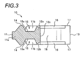
- Fig. 3 is a sectional view taken along a III-III line in Fig. 2 .
- a forward and rearward direction means a direction parallel to a tape width direction of a fastener tape, on which the fastener element is attached, and is also referred to as an element length direction.
- the front direction refers to a direction, toward which an engaging head portion of the fastener element is arranged relative to a body portion thereof
- the rear direction refers to a direction, toward which leg portions of the fastener element are arranged relative to the body portion.
- a right and left direction means a direction parallel to a tape front-and-back direction of the fastener tape and is also referred to as an element width direction.
- an upward and downward direction means a direction parallel to a tape length direction of the fastener tape and is also referred to as an element thickness direction.
- the fastener element 10 of the present embodiment 1 is constructed of metal, such as cooper alloy, nickel alloy or aluminum alloy.
- the fastener element 10 includes an engaging head portion 11 having engaging protrusion portions 14 and fitting space portions 15, a body portion 12 arranged on a rear end of the engaging head portion 11, and right and left leg portions 13 extending to be bifurcated from a rear end of the body portion 12, and is configured as a double side element in which one engaging head portion 14 and one fitting space portion 15 are arranged in one set on each of an upper surface (first main surface) and lower surface (second main surface) of the engaging head portion 11.
- the fastener element 10 is formed so that front and back sides thereof are symmetrical with respect to a center position thereof in the element thickness direction and also is formed so that right and left sides thereof are symmetrical with respect to a center position thereof in the element width direction.
- the body portion 12 refers to a part, which is arranged from an end edge location of bottom surfaces 15a of the fitting space portions 15 to a location of a tape nipping surface 18 along the element length direction (front and back direction), and thus a part arranged front of the body portion 12 is referred to as the engaging head portion 11, and a part arranged rear of the body portion 12 is referred as the leg portions 13.
- the fastener element 10 is shown in a state before being attached to a fastener tape 2, and thus the right and left leg portions 13 are spread in the element width direction and the fastener element 10 has a generally Y shape as viewed from the upper or lower side thereof.
- the engaging head portion 11 includes a thin plate-shaped head body 11 a (also referred to as a base portion) having a constant dimension in the upward and downward direction (element thickness direction) between an upper surface (first main surface) and a lower surface (second main surface) thereof, the engaging protrusion portions 14 formed so as to protrude from the upper and lower surfaces of the head body 11 a, and right and left extension portions 11b extending forward from the body portion 12 on the upper and lower surfaces of the head body 11a.
- a thin plate-shaped head body 11 a also referred to as a base portion having a constant dimension in the upward and downward direction (element thickness direction) between an upper surface (first main surface) and a lower surface (second main surface) thereof, the engaging protrusion portions 14 formed so as to protrude from the upper and lower surfaces of the head body 11 a, and right and left extension portions 11b extending forward from the body portion 12 on the upper and lower surfaces of the head body 11a.
- the head body 11a of the engaging head 11 is formed so as to have a predetermined thickness set so that an element thickness-direction dimension is smaller than that of the body portion 12 by interposing a step therebetween. Also, a front end edge (leading end edge) of the head body 11a is arranged to be parallel to the element width direction. Right and left side edges of the head body 11 a are inclined or curved relative to the element length direction, when the fastener element 10 is viewed from the upper or lower side, so that a dimension of the head body 11a in the element width direction is gradually reduced toward the front end edge thereof.
- the engaging protrusion portions 14a on the upper and lower surfaces are formed so as to protrude in a mountain shape from the upper and lower surfaces of the head body 11a by the middle portion, in the element width direction, of the front end portion of the head body 11a, and are arranged at a predetermined distance from the body portion 12.
- the right and left extension portions 11b are arranged at locations spaced from each other to have a predetermined element thickness-direction dimension raised from the head body 11a and also to extend from right and left outer side portions 12b, as described below, of the body portion 12 toward right and left sides of the engaging protrusion portions 14. In this case, predetermined gaps are provided between the engaging protrusion portions 14 and the right and left extension portions 11b.
- Upper and lower surfaces of the right and left extension portions 11b are arrange on the same planes as those of upper and lower surfaces of right and left outer side portions 12b of the body portion 12b or right and left outer side edge portions of the leg portions 13. Also, inner surfaces of the right and left extension portions 11b are formed in a tapered shape inclined relative to the upward and downward direction, so that an element width-direction dimension of each extension portion 11b is gradually increased as it approaches a height location of the bottom surface 15a of the respective fitting space portions 15.
- fitting space portions 15 surrounded by engaging protrusion portions 14, right and left extension portions 11b and body portion 12 are respectively formed in the upper and lower surfaces of the head body 11 a.
- Each fitting space portion 15 has a bottom surface 15a set at the same position (height location) in the element thickness direction as those of the upper and lower surfaces of the head body 11a.
- the body portion 12 in the present embodiment 1 has, at the middle portion in the element width direction of the body portion 12, a bridge portion 12a raised from the bottom surfaces 15a of the fitting space portions 15 in the element thickness direction and having an element thickness-direction dimension larger than that of the head body 11a of the engaging head portion 11, and also has outer side portions 12b arranged on both right and left sides of the bridge portion 12a.
- the bridge portion 12a of the body portion 12 is arranged along the element width direction between the fitting spaces portions 15 and a crotch portion 12c (tape nipping surface 18), as described below, to connect base end portions of the right and left leg portions 13. Also, as shown in Fig. 3 , the bridge portion 12a has inclined surfaces, which are inclined downward and forward, on the side of the bridge portion 12a which is located toward the fitting space portions 15.
- the right and left outer side portions 12b of the body portion 12 have upper and lower surfaces formed so as to be parallel to each other and also to be flat. Further, the upper and lower surfaces of the right and left outer side portions 12b (in particular, outer side edge portions) are arranged to be continued to upper and lower surfaces of the right and left extension portions 11b and upper and lower surfaces of the outer side edge portions of the right and left leg portions 13, and also an element thickness-direction dimension of the right and left outer side portions 12b is set to have the same size as an element thickness-direction dimension of the right and left extension portions 11b and an element thickness-direction dimension of the outer side edge portions of the right and left leg portions 13.
- the body portion 12 of the present embodiment 1 has the bridge portion 12a arranged between the right and left outer side portions 12b thereof, strength of the body portion 12 can be effectively enhanced, and thus the body portion 12 can be configured to be hardly deformed upon crimping of the fastener element 10.
- thinning portions 16 are arranged to be inclined downward toward the tape nipping surface 18 as described below.
- the thinning portions 16 of the body portion 12 are formed so as to be inclined downward as described above, an element length-direction (forward and rearward direction) thickness of the bridge portion 12a can be easily ensured, for example, as compared to a case where thinning portions are constructed by recessed portions recessed in a step shape toward a tape nipping surface, thereby enhancing strength of the bridge portion 12a.
- the right and left leg portions 13 of the present embodiment 1 extend to be branched in the right and left direction while interposing therebetween the crotch portion 12c on the rear end of the body portion 12. Also, on leading end portions (rear end portions) of the right and left leg portions 13, hook-shaped bent portions 13a are arranged to be bent in directions approaching each other (inward directions).
- upper and lower surfaces of the outer side edge portion of each leg portion 13 are formed by flat surfaces parallel to each other, and an element thickness-direction dimension of the outer side edge portion of the leg portion 13 as measured between the upper and lower surfaces thereof is set to have a predetermined constant size in consideration of the exterior or appearance of a slide fastener, contacting thereof with a slider upon sliding of the slider and the like.
- an element thickness-direction dimension of the outer side edge portions of the body portion 12 is also set to have the same predetermined constant size as the element thickness-direction dimension of the outer side edge portions of the leg portions 13.
- inner peripheral surfaces of the body portion 12 and right and left leg portions 13 are arranged to be parallel to each other in the element thickness direction.
- the inner peripheral surfaces include leading end surfaces of the bent portions 13a of the right and left leg portions 13, which are oriented inward (toward the center position in the element width direction), and also has a single continuous surface, which continuously extends from the leading end surface of the bent portion 13a of one leg portion 13 (left leg portion 13) to the leading end surface of the bent portion 13a of the other leg portion 13 (right leg portion 13) through the body portion 12.
- the inner peripheral surface of the fastener element 10 becomes the tape nipping surface 18 intended to be tightly contacted (pressed against) with the fastener tape 2 when the fastener element 10 is attached to the fastener tape 2 to interpose the tape side edge portion of the fastener tape 2 as described below.
- upper and lower surface-side portions of the body portion 12 and right and left leg portions 13 of the fastener element 10 arranged to continuously extend along the tape nipping surface 18 are referred to as inner peripheral edge portions.
- upper and lower surface-side portions of the body portion 12 and right and left leg portions 13 of the fastener element 10 arranged to continuously extend along a peripheral surface (i.e., an outer peripheral surface), which is not the tape nipping surface 18, are referred to as outer peripheral edge portions
- the outer peripheral edge portions includes outer side edge portions arranged along outer side surfaces of the body portion 12 and right and left leg portions 13 and rear end edge portions arranged along rear end surfaces of the leg portions 13 oriented toward the inner side of the tape.
- the outer side surfaces of the body portion 12 and right and left leg portions 13 means surfaces which are arranged to be spaced form the fastener tape 2 and also to be parallel (including a generally parallel state) to tape front and back surfaces when the fastener element 10 is attached to the fastener tape 2.
- the thinning portions 16 for reducing a dimension (i.e., an element thickness-direction dimension) between upper and lower surfaces are arranged along the tape nipping surface (inner peripheral surface) 18 of the body portion 12 and right and left leg portions 13 on element upper and lower surfaces to be symmetrical at front and back sides thereof.
- an element thickness-direction dimension of a region of the inner peripheral edge portions, in which the thinning portions 16 are arranged becomes smaller than the element thickness-direction dimension of the outer side edge portions of the right and left leg portions 13.
- a thickness of the tape nipping surface 18 in the region in which the thinning portions 26 are arranged becomes a thin thinness portion having a thickness thinner than the element thickness-direction dimension of the outer side edge portions of the right and left leg portions 13.
- the thinning portions 16 may be provided on element upper and lower surfaces to be asymmetrical at front and back sides.
- the thinning portions 16 are constructed by downward inclined surfaces for gradually reducing the element thickness-direction dimension toward the tape nipping surface 18.
- the thinning portions 16 may be constructed by a curved surface for gradually reducing the element thickness-direction dimension toward the tape nipping surface 18.
- a dimension of the thinning portions 16 in a downward inclined direction is set to be in a range of 5% or more and 50% or less of a minimum distance dimension between the tape nipping surface (inner peripheral surfaces) 18 and outer side surfaces of the right and left leg portions 13, preferably a range of 7% or more and 30% or less.
- the fastener element 10 can be strongly pressed against the fastener tape by only substantially the tape nipping surface 18 when the fastener element 10 is attached to the fastener tape 2 as described below, thereby reducing a contact area of the fastener element 10 to the fastener tape 2.
- the dimension of the thinning portions 16 is set to be 50% or less of the minimum distance dimension between the tape nipping surface 18 and the outer side surfaces, it is possible to prevent strength of the body portion 12 or leg portions 13 of the fastener element 10 from being significantly decreased even if the thinning portions 16 are provided on the body portion 12 and the leg portions 13. Also, when the fastener element 10 is attached to the fastener tape 2 to construct the fastener stringer 1, the thinning portions 16 of the fastener element 10 can be configured to be hardly seen from the outside.
- the thinning portions 16 are continuously arranged along the tape nipping surface 18 from the bent portion 13a of the one (left) leg portion 13 to the bent portion 13a of the other (right) leg portion 13 through the body portion 12, except parts of leading end portions of the bent portions 13a of the right and left leg portions 13.
- the thin thickness portion is continuously arranged along the tape nipping surface 18 from the bent portion 13a of the one (left) leg portion 13 to the bent portion 13a of the other (right) leg portion 13 through the body portion 12, except parts of leading end portions of the bent portions 13a of the right and left leg portions 13 (i.e., the thinning portions are continuously arranged along the inner peripheral edge portion, except parts of leading end portions of the bent portions 13a).
- non-thinning portions 17, which have the same element thickness-direction dimension as those of the outer side portion 12b of the body portion 12 and the outer side edge portions of the right and left leg portions 13, are arranged in a range of parts of the leading end portions of the bent portions 13a, which extend along the tape nipping surface 18, in particular on corner portions of the leading end portions of the bent portions 13a, which are located on the outer peripheral side thereof.
- the rectangular wire material which has been subject to edge cutting, is punched using a cutting punch and a cutting die to follow an outer peripheral shape of the fastener element 10, and then the obtained element-shaped metal pieces is polished, painted or the like, thereby obtaining the fastener element 10 of the present embodiment 1 shown in Fig. 1 .
- the fastener element 10 of the present embodiment 1 obtained as described above is manufactured in a state where a pair of right and left leg portions 13 are spread out in the right and left direction as they go from front end portions thereof, which are located on the body portion 12, toward rear end portions thereof. Accordingly, the fastener element 10 is attached (planted) to the fastener tape 2 by inserting the tape side edge portion of the fastener tape 2 between the right and left leg portions 13, and additionally, crimping the right and left leg portions 13 in inward directions approaching each other to plastically deform the fastener element 10.
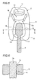
- the fastener tape 2 of the present embodiment 1 has a core string portion 2a arranged along a tape inner side edge thereof, and thus in a state where the fastener tape 2 is tensioned in a tape length direction so that a tension is applied to the fastener tape 2, the fastener element 10 is attached to the fastener tape 2 so that the fastener element 10 straddles and embraces the core string portion 2a of the fastener tape 2.
- the bridge portion 12a having an element thickness-direction dimension larger than that of the head body 11a of the engaging head portion 11 is arranged on the body portion 12, thereby increasing strength of the body portion 12. Accordingly, the body portion 12 can be configured to be hardly deformed even if the right and left leg portions 13 are crimped and plastically deformed upon attaching of the fastener element 10.
- the shape of the fitting space portions 15 arranged on the engaging head portion 11 can be stably maintained. Additionally, when the fastener element 10 is attached to the fastener tape 2 by crimping, it is possible to effectively prevent an attachment position of the fastener element to the fastener tape from being dislocated or a posture of the fastener element 10 from being inclined, thereby allowing the fastener element 10 to be planted at a predetermined position in a correct posture.
- the bridge portion 12a is arranged on the fastener element 10 of the present embodiment 1, the core string portion 2a of the fastener tape 2 is pressed by the bridge portion 12a of the fastener element 10 when the fastener element 10 is attached to the fastener tape 2, and therefore, it is possible to inhibit the core string portion 2a from being swollen to be bulged toward the fitting space portions 15 of the fastener element 10.
- the core string portion 2a of the fastener tape 2 is pressed by the bridge portion 2a of the fastener element 10, the core string portion 2a of the fastener tape 2 is hardly directly contacted with the counterpart fastener element 10 when the right and left fastener elements 10 are engaged with and disengaged from each other. Accordingly, even if operations of opening and closing the slide fastener by sliding the slider are repeated, a nap is hardly occurred on the core string portion 2a of the fastener tape 2, and thus a problem that engagement of fastener elements 10 becomes poor, for example, due to occurrence of a nap on the core string portion 2a or the like can be prevented in advance.
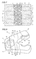
- a plurality of fastener elements 10 are successively attached to the tape side edge portion of the fastener tape 2 at a predetermined pitch, thereby obtaining the fastener stringer 1 as shown in Fig. 4 .
- two obtained fastener stringers 1 are combined as one set, and also a slider, not shown, is slidingly attached along element rows of right and left fastener stringers 1, thereby constructing the slide fastener.
- the fastener stringer 1 is configured so that the attachment pitch of the fastener elements 10 in the tape length direction is narrower than that of the case of, for example, a general fastener stringer 1 of the related art.
- the fastener stringer 1 is configured so that a relationship of 'D1 ⁇ (P-D1)' is satisfied, where the attachment pitch of the fastener elements 10 is 'P' and a distance between outer peripheral surfaces of fastener elements 10 adjacent to each other in the tape length direction is 'D1'.
- the attachment pitch of the fastener elements 10 means a distance between center positions, in the tape length direction (element thickness direction), of fastener elements 10 adjacent to each other in the tape length direction.
- the fastener stringer 1 is configured so that the relationship of 'D1 ⁇ (P-D1)' is satisfied, namely, a magnitude of D1 is smaller than the element thickness-direction dimension of the outer side portion 12b of the body portion 12 and the outer side edge portions of the leg portions 13 of each fastener element 10 and thus the attachment pitch of the fastener elements 10 becomes narrower, the fastener elements 10 can be finely arrayed in the tape length direction so that the fastener tape 2, which would otherwise exposed between fastener elements 10 of element rows, is hardly seen.
- the appearance of the fastener stringer 1 can become better, design ability of the slide fastener can be enhanced and also luxury feeling can be imparted to the slide fastener.
- the thinning portions 16 are provided on the upper and lower surfaces of each fastener element 10. Accordingly, the relationship of 'D1 ⁇ (P-D1)' is satisfied and also a relationship of 'D2 > (P-D1)' is satisfied, where a distance between tape nipping surfaces 18 of fastener elements 10 adjacent to each other in the tape length direction as measured at portions (thin thickness portion) which are provided with the thinning portions 16 is 'D2'.
- a magnitude of D2 can be set to be larger than the element thickness-direction dimension of the outer side edge portions of the leg portions 13 of each fastener element 10.
- the thinning portions 16 of each fastener element 10 becomes a tape non-contact portion, which is not contacted with the fastener tape 2, a contact area of fastener elements 10 to the fastener tape 2 (in particular, a contact area thereof to the core string portion 2a of the fastener tape 2) can be reduced even if the fastener elements 10 are attached to the fastener tape 2 at the narrower attachment pitch.
- a tape length-direction dimension (i.e., 'D2') of a tape region between adjacent fastener elements 10, which is not gripped by the fastener elements 10, i.e., a tape region between tape nipping surfaces 18 of the adjacent fastener elements 10
- a distance i.e., 'D1'
- the magnitude P of the attachment pitch of fastener elements 10 is set to be 2.11 mm or more and 2.20 mm or less and the distance D1 between outer peripheral surfaces of adjacent fastener elements 10 is set to be 0.96 mm or more and 1.00 mm or less.
- the element thickness-direction dimension (P-D1) of the outer side edge portions of the leg portions 13 of each fastener element 10 is set to be 1.11 mm or more and 1.24 mm or less, preferably 1.15 mm or more and 1.20 mm or less.
- the distance D2 between tape nipping surfaces 18 of adjacent fastener elements 10 as measured at portions which are provided with the thinning portions 16 is set to be 1.36 or more and 1.40 mm or less. Meanwhile, when such dimensions are relatively represented, assuming that P is 100%, D1 is set to be in a range of 40% or more and 50% or less and D2 is set to be 55% or more and 65% or less.
- the tape region of the fastener tape 2 between fastener elements 10 can be properly ensured, and accordingly reduction in pliability or flexibility of the fastener stringer 1 can be inhibited even if the attachment pitch of fastener elements 10 is narrower. Also, reduction in sliding ability of the slider associated with reduction in pliability or flexibility of the fastener stringer 1 can be inhibited.
- the fastener stringer 1 of the present embodiment because the tape region between fastener elements 10 can be suitably ensured as described above, stretchability of the element attachment portion of the fastener tape 2 can be properly ensured and thus a difference in shrinkage amount between the element attachment portion and the tape main body portion can be reduced. Accordingly, even when the fastener stringer 1 is manufactured so that the fastener elements 10 have a narrower attachment pitch, puckering can be hardly occurred on the fastener stringer 1.
- the fastener stringer 1 of the present embodiment even if the thinning portions 16 are provided on each fastener element 10, the thinning portions 16 of each fastener element 10 can be configured to be hardly seen from the outside, because the outer side edge portions of the body portion 12 and right and left leg portions 13 have a predetermined thickness dimension. Accordingly, in the present embodiment 1, pliability of the fastener stringer 1 can be enhanced, and thus harmful effects that the appearance of the slider fastener becomes poor or the exterior thereof gets damaged are not occurred.
- each fastener element 10 has a predetermined thickness dimension, when the slider of the slide fastener is slid in a closing direction, each fastener element 10 which enters an element guide passage of the slider can be suitably contacted with an element guide surface inside the slider. Accordingly, a posture of each fastener element 10 can be prevented from being inclined in the element guide passage of the slider, thereby allowing right and left fastener elements 10 to be smoothly engaged with each other.
- the fastener stringer may be, of course, constructed by attaching the fastener elements 10 to the fastener tape 2 in such a manner that the attachment pitch of the fastener elements 10 is not set to be narrower as described above, but the attachment pitch is set to have the same size as, for example, those of a conventional general fastener stringer.
- the tape region of the fastener tape between fastener elements 10 are larger than that of a conventional general fastener stringer, thereby enhancing pliability or flexibility of the fastener stringer.
- Fig. 8 is a perspective view showing a fastener element according to the present embodiment 2.
- Fig. 9 is a plan view showing the fastener element and
- Fig. 10 is a sectional view taken along a X-X line in Fig. 9 .
- the fastener element 20 of the present embodiment 2 is constructed of metal and also includes an engaging head portion 21 having engaging protrusion portions 24 and fitting space portions 25, a body portion 22 arranged on a rear end of the engaging head portion 21, and right and left leg portions 23 extending to be bifurcated from a rear end of the body portion 22.
- the fastener element 20 of the present embodiment 2 is configured as a double side element in which one set of engaging head portion 24 and fitting space portion 25 is arranged on each of upper and lower surfaces of the engaging head portion 21. Further, the fastener element 20 is formed so that front and back sides thereof are symmetrical with respect to a center position thereof in the element thickness direction and also is formed so that right and left sides thereof are symmetrical with respect to a center position thereof in the element width direction.
- the engaging head portion 21 includes a flat plate-shaped head body 21 a having an element thickness-direction dimension smaller than that of the body portion, engaging protrusion portions 24 formed so as to protrude in a mountain shape from upper and lower surfaces of the head body 21a, and right and left extension portions 21b extending forward from the body portion 22 on the upper and lower surfaces of the head body 21 a. Also, the right and left extension portions 21b are arranged at spaced locations to have an element thickness-direction dimension larger than that of the head body 21a and also to extend forward from the body portion 22.
- Upper and lower surfaces of the right and left extension portions 21b are arranged on the same planes as those of upper and lower surfaces of right and left outer side portions 22b of the body portion 12b or right and left outer side edge portions of the leg portions 23. Also, inner surfaces of the right and left extension portions 21b are formed in a tapered shape inclined relative to the upward and downward direction, so that an element width-direction dimension of each extension portion 21b is gradually increased as it approaches a height location of a bottom surface 25a of the respective fitting space portions 25.
- fitting space portions 25 surrounded by the engaging protrusion portions 24, right and left extension portions 21b and body portion 22 are respectively formed in the upper and lower surfaces of the head body 21a.
- Each fitting space portion 15 has a bottom surface 15a set at the same position (height location) in the element thickness direction as those of the upper and lower surfaces of the head body 21a.
- the body portion 22 in the present embodiment 2 has, at the middle portion in the element width direction of the body portion 22, a bridge portion 22a raised from the bottom surfaces 15a of the fitting space portions 15 in the element thickness direction and having an element thickness-direction dimension larger than that of the head body 21a of the engaging head portion 21, and also has outer side portions 22b arranged on both right and left sides of the bridge portion 22a.
- the bridge portion 22a of the body portion 22 is arranged along the element width direction to connect base end portions of the right and left leg portions 23 with each other. Also, upper and lower surfaces of the bridge portion 22a of the body portion 22 and upper and lower surfaces of right and left outer side portions 22b of the body portion 22 are configured to be flushed with each other.
- element thickness-direction dimensions of the bridge portion 22a and the right and left outer side portions 22b of the body portion 22 are set to have the same predetermined size as an element thickness-direction dimension of the right and left extension portions 21b and an element thickness-direction dimension of the outer side edge portions of the right and left leg portions 23.
- the bridge portion 22a has a tapered inclined surface, which is inclined downward and forward, on the side thereof which is located toward the fitting space portions 25.
- the right and left leg portions 23 of the present embodiment 2 extend to be branched in the right and left direction while interposing therebetween a crotch portion 22c arranged on the rear end of the body portion 22. Further, on inner peripheral edge portions of the right and left leg portions 23, recessed portions 23b are provided along the element thickness direction to allow a part of a core string portion 2a of a fastener tape 2 to be inserted therein, and also on leading end portions (rear end portions) of the right and left leg portions 23, hook-shaped bent portions 23a are arranged to be bent in directions approaching each other (inward directions).
- Upper and lower surfaces of the outer side edge portion of the right and left leg portions 23 are formed by flat surfaces parallel to each other, and an element thickness-direction dimension of the outer side edge portion of the leg portions 23 is set to have a predetermined size in consideration of the exterior or appearance of a slide fastener, contacting thereof with a slider upon sliding of the slider and the like.
- inner peripheral surfaces of the body portion 22 and right and left leg portions 23 are arranged to be parallel to each other in the element thickness direction.
- the inner peripheral surfaces include leading end surfaces of bent portions 23a of the right and left leg portions 23, which are oriented inward (toward the center position in the element width direction), and also arranged to continuously extend from the leading end surface of the bent portion 23a of one (left) leg portion 23 to the leading end surface of the bent portion 23a of the other (right) leg portion 23 through the body portion 22.
- the inner peripheral surfaces become a tape nipping surface 28 intended to be tightly contacted with the fastener tape 2 when the fastener element 20 is attached to the fastener tape 2.
- thinning portions 26 for reducing a dimension (i.e., an element thickness-direction dimension) between upper and lower surfaces thereof are arranged along the tape nipping surface 28 on element upper and lower surfaces to be symmetrical at front and back sides thereof.
- an element thickness-direction dimension of a region of the inner peripheral edge portions, in which the thinning portions 26 are arranged becomes smaller than the element thickness-direction dimension of the outer side edge portions of the right and left leg portions 23.
- a thickness of the tape nipping surface 28 in regions in which the thinning portions 26 are arranged becomes a thin thinness portion having a thickness thinner than the element thickness-direction dimension of the outer side edge portions of the right and left leg portions 23.
- the thickness of the tape nipping surface 28 in regions in which the thinning portions 26 are arranged becomes a thin thickness portion having a thickness thinner than a thickness of the tape nipping surface 28 in a region configured as non-thinning portions 27 as described below.
- the thinning portions 26 of the present embodiment 2 are partially provided on the continuous inner peripheral edge portions of the body portion 22 and right and left leg portions 23.
- the thinning portions 26 of the present embodiment 2 are arranged to be split into right and left sides on the inner peripheral edge portions of a region of the leg portions 23.
- inner peripheral edge portions of base end portions of the right and left leg portions 23 and a rear end portion (crotch portion 22c) of the body portion 22 are configured as the non-thinning portions 27 having the same element thickness-direction dimension as that of the outer side edge portions of the right and left leg portions 23.
- the thinning portions 26 are constructed by recessed portions recessed relative to upper and lower surfaces of the right and left leg portions 23 except the thinning portions 26, so as to be cut out in a step shape toward the tape nipping surface 28. Also, when the fastener element 20 is viewed from the upper or lower side, a dimension of the regions, in which the thinning portions 26 are formed, as measured from the tape nipping surface 28 is set to be in a range of 5% or more and 50% or less of a minimum distance dimension between the tape nipping surface 28 and outer side surfaces of the right and left leg portions 23, preferably a range of 7% or more and 30% or less.
- the fastener element 20 of the present embodiment 2 is manufactured by sequentially pressing, edge cutting and punching a rectangular wire material made of metal and then polishing or painting an element-shaped metal piece punched from the rectangular wire material.
- the fastener element 20 of the present embodiment 2 manufactured in a state where a pair of right and left leg portions 23 are spread out is attached to the fastener tape 2 to straddle and embrace the core string portion 2a of the fastener tape 2 by inserting a tape side edge portion of the tensioned fastener tape 2 between the right and left leg portion 23 and additionally crimping the right and left leg portions 23 in inward directions approaching each other to plastically deform the fastener element 20.
- the body portion 22 in the fastener element 20 of the present embodiment 2 has a strength increased by the bridge portion 22a arranged between the fitting space portions 25 and the tape nipping surface 28, the body portion 22 can be configured to be hardly deformed even if the right and left leg portions 23 are crimped.
- a plurality of fastener elements 20 of the present embodiment 2 are successively attached to the tape side edge portion of the fastener tape 2 at a predetermined attachment pitch, thereby manufacturing the fastener stringer.
- the fastener stringer is manufactured so that the fastener elements 20 have a narrower attachment pitch, thereby satisfying a relationship of 'D1 ⁇ (P-D1)', where the attachment pitch of the fastener elements 20 is 'P' and a distance between outer peripheral surfaces of fastener elements 20 adjacent to each other in the tape length direction is 'D1'. Accordingly, like the foregoing embodiment 1, design ability of the slide fastener can be enhanced or luxury feeling can be imparted to the slide fastener.
- the thinning portions 26 are provided on the upper and lower surfaces of each fastener element 20. Accordingly, where a distance between tape nipping surfaces 28 of adjacent fastener elements 20 as measured at portions which are provided with the thinning portion 26 is 'D2', a magnitude of D2 can be set to be larger than the element thickness-direction dimension of the outer side portions 22b of the body portions 22 and the outer side edge portions of the right and left leg portions 23 of each fastener element 20 so that a relationship of 'D2 > (P-D1)' is satisfied. Also, a contact area of fastener elements 20 to the fastener tape 2 can be reduced.
- the thinning portions 26 are arranged on inner peripheral edge portions of the recessed portion 23b and bent portion 23a of each leg portion 23, and also the base end portions of the right and left leg portion 23 and the rear end portion (crotch portion 22c) of the body portion 22 are configured as the non-thinning potions 27. Accordingly, in the fastener element 20 of the present embodiment 2, a formation range of the thinning portion 26 along the tape nipping surface 28 is limited as compared to the fastener element 10 in which the thinning portions 16 are arranged to continuously extend from the bent portion 13a of the one leg portion 13 to the bent portion 13a of the other leg portion 13 through the body portion 12 as in the foregoing embodiment 1.
- a contact area of each fastener element 20 to the fastener tape 2 can be increased as compared to the fastener element 10 of the foregoing embodiment 1 because the formation range of the thinning portions 26 is limited, thereby enhancing an attachment strength of the fastener element 20.
- the fastener element of the present embodiment 2 can ensure pliability or flexibility as described above, and also the attachment position of the fastener element 20 to the fastener tape 2 can hardly be slipped in the tape length direction to enhance slippage strength of the fastener element 20. Accordingly, pliability and flexibility of the fastener stringer and slippage strength of the fastener element 20 are combined to be well balanced.
- the thinning portions 26 in the present embodiment 2 are constructed by recessed portions recessed so as to be cut out in a step shape toward the tape nipping surface 28, the present invention is nor particularly limited to the shape of the thinning portions 26, and thus, for example, the thinning portions 26 may be constructed by inclined surfaces, which are inclined downward toward the tape nipping surface as in the case of the foregoing embodiment 1.
- Fig. 13 is a plan view showing a fastener element according to the preset embodiment 3.
- the fastener element 30 of the present embodiment 3 is different from the fastener element 10 of the foregoing embodiment 1 in terms of a formation range of thinning portions 36, which are provided on a body portion 12 and right and left leg portions 13, along a tape nipping surface 18, and thus configurations other than the formation range of the thinning portion 36 are the same as those of the fastener element 10 of the foregoing embodiment 1.
- the fastener element 30 of the present embodiment 3 includes an engaging head portion 11 having engaging protrusion portions 14 and fitting space portions 15, a body portion 12 arranged on a rear end of the engaging head portion 11, and right and left leg portions 13 extending to be bifurcated from a rear end of the body portion 12 and is configured as a double side element having a symmetrical shape with respect to center positions thereof in the front and back direction and the right and left direction.
- the engaging head portion 11 includes a flat plate-shaped head body 11a having a constant element thickness-direction dimension, engaging protrusion portions 14 formed so as to protrude from upper and lower surfaces of the head body 11 a, and right and left extension portions 11b extending forward from the body portion 12 on the upper and lower surfaces of the head body 11a. Also, fitting space portions 15 surrounded by engaging protrusion portions 14, right and left extension portions 11b and body portion 12 and each having a bottom surface 15a are respectively formed in the upper and lower surfaces of the head body 11a.
- the body portion 12 has a bridge portion 12a arranged at a center portion thereof in the element width direction and outer side portions 12b arranged on both right and left sides of the bridge portion 12a. Also, on leading end portions of the right and left leg portions 13, hook-shaped bent portions 13a are arranged to be bent in directions approaching each other (inward directions).
- thinning portions 36 for reducing an element thickness-direction dimension relative to outer side edge portions of the leg portions 13 are arranged along the tape nipping surface 18 on element upper and lower surfaces. Namely, like the foregoing embodiment 2, the thinning portions 36 of the present embodiment 3 are partially provided on the continuous inner peripheral edge portions of the body portion 12 and right and left leg portions 13.
- inner peripheral edge portions of the bent portions 13a of the right and leg portions 13 and inner peripheral edge portions of parts (middle portions) between the bent portions 13a and the base end portions thereof are configured as non-thinning portions 37 having the same element thickness-direction dimension as that of the outer side edge portions of the leg portions 13.
- the thickness of the tape nipping surface 18 in regions in which the thinning portions 36 are arranged becomes a thin thickness portion having a thickness thinner than a thickness of the tape nipping surface 28 in regions of non-thinning portions 37 in which the thinning portions 36 are not arranged.
- the thinning portions 36 of the present embodiment 3 are constructed by downward inclined surfaces for gradually reducing the element thickness-direction dimension toward the tape nipping surface 18 Also, when the fastener element 30 is viewed from the upper or lower side, a dimension of the regions, in which the thinning portions 36 are formed, as measured from the tape nipping surface 18 is set to be in a range of 5% or more and 50% or less of a minimum distance dimension between the tape nipping surface 18 and outer side surfaces of the right and left leg portions 13, preferably a range of 7% or more and 30% or less.
- the thinning portion 36 of the present embodiment 3 may not be constructed by inclined bottom surfaces, but by recessed portions recessed relative to upper and lower surfaces of the right and left leg portions 13 so as to be cut out in a step shape toward the tape nipping surface 18 as in the case of the foregoing embodiment 2.
- the fastener element 30 of the present embodiment 3 is attached to the fastener tape 2 to straddle and embrace the core string portion 2a of the fastener tape 2 by inserting a tape side edge portion of the tensioned fastener tape 2 between the right and left leg portion 13 and additionally crimping the right and left leg portions 13 in inward directions approaching each other to plastically deform the fastener element 30.
- the body portion 12 in the fastener element 30 of the present embodiment 3 has a strength increased by the bridge portion 12a arranged between the bottom surfaces 15a of the fitting space portions 15 and the tape nipping surface 18, the body portion 12 can be configured to be hardly deformed even if the right and left leg portions 23 are crimped.
- a plurality of fastener elements 30 of the present embodiment 3 are successively attached to the tape side edge portion of the fastener tape 2 at a predetermined attachment pitch, thereby manufacturing the fastener stringer.
- the fastener stringer in the present embodiment 3 is manufactured so that the fastener elements 30 have a narrower attachment pitch to satisfy a relationship of 'D1 ⁇ (P-D1)'. Accordingly, design ability of the slide fastener can be enhanced or luxury feeling can be imparted to the slide fastener.
- the fastener element 30 of the present embodiment 3 can be configured so that pliability and flexibility of the fastener stringer and slippage strength of the fastener element 30 are combined to be well balanced.
- Fig. 14 is a perspective view showing a fastener element according to the present embodiment 4.
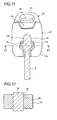
- Fig. 15 is a sectional view of the fastener element. Meanwhile, in Figs. 14 and 15 , the fastener element is shown in a state where the fastener element is attached to the fastener tape (i.e., a state where right and left leg portions are pressed inward to be plastically deformed).
- the fastener element 40 of the present embodiment 4 is constructed of metal, such as cooper alloy, nickel alloy or aluminum alloy. Also, the fastener element 40 includes an engaging head portion 41 having an engaging protrusion portion 44 and an engaging concave portion 45, a body portion 42 arranged on a rear end of the engaging head portion 41, and right and left leg portions 43 extending to be bifurcated from a rear end of the body portion 42.
- the fastener element 40 is configured as a single side element in which the engaging protrusion portion 44 and the engaging concave portion 45 are respectively arranged on opposing sides of the engaging head portion 41, and also right and left sides thereof are symmetrical with respect to a center position thereof in the element width direction.
- the engaging head portion 41 of the present embodiment 4 has a head body 41a configured so that an element thickness-direction dimension between upper and lower surfaces thereof has a constant size, an engaging protrusion portion 44 formed so as to protrude in a mountain shape from the lower surface of the head body 41a, and the engaging concave portion 45 concavely provided in the upper surface of the head body 41a. Also, the engaging protrusion portion 44 and the engaging concave portion 45 are arranged so that positions thereof correspond to each other.
- the body portion 42 is arranged to extend from an end edge location of the engaging concave portion 45 to a location of a tape nipping surface 48 in the element length direction (front and back direction).
- An upper surface of the body portion 42 is arranged at a location raised from a bottom surface 45a of the engaging concave portion 45 in the element thickness direction and is formed so as to be flushed with the upper surface of the head body 41 a.
- the right and left leg portions 43 extend rearward form the body portion 42, and on leading end portions (rear end portions) of the right and left leg portions 43, hook-shaped bent portions 43a are arranged to be bent in directions approaching each other (inward directions). Also the right and left leg portions 43 (except thinning portions 46 as described below) have upper and lower surfaces formed so as to be parallel to each other and also to be flat, and an element thickness-direction dimension between the upper and lower surfaces of the leg portions 43 is set to have the same size as an element thickness-direction dimension between the upper and lower surfaces of the head body 41s of the engaging head portion 41 and an element thickness-direction dimension between the upper and lower surfaces of the body portion 42.
- inner peripheral surfaces of the body portion 42 and right and left leg portions 43 are arranged to be parallel to each other in the element thickness direction.
- the inner peripheral surfaces become a tape nipping surface 48 intended to be tightly contacted with the fastener tape 2 when the fastener element 40 is attached to the fastener tape 2.
- thinning portions 46 for reducing an element thickness-direction dimension relative to outer side edge portions of the leg portions 43 are arranged along the tape nipping surface 18 on element upper and lower surfaces to be symmetrical at front and back sides thereof.
- the thinning portions 46 of the present embodiment 4 are arrange to continuously extend from a leading end of each leg portion 43 to a base end portion of the leg portion 43.
- body portion-side end portions of the right and left leg portions 43 and a rear end portion (crotch portion 42a) of the body portion 42 are configured as the non-thinning portions 47 having the same element thickness-direction dimension as that of the outer side edge portions of the right and left leg portions 43.
- the thickness of the tape nipping surface 48 in regions in which the thinning portions 46 are arranged becomes a thin thickness portion having a thickness thinner than a thickness of the tape nipping surface 48 in regions of non-thinning portions 47 in which the thinning portions 46 are not arranged.
- the thinning portions 46 in the present embodiment 4 are constructed by recessed portions recessed so as to be cut out in a step shape toward the tape nipping surface 48. Also, when the fastener element 40 is viewed from the upper or lower side, a dimension of the regions, in which the thinning portions 46 are formed, as measured from the tape nipping surface 48 is set to be in a range of 5% or more and 50% or less of a minimum distance dimension between the tape nipping surface 48 and outer side surfaces of the leg portions 43.
- the fastener element 40 of the present embodiment 4 is manufactured in a state where the a pair of right and left leg portions 43 are spread out, by slicing a generally Y-shaped cross-sectioned metal wire material, called to as a Y bar, at a predetermined thickness and then pressing or the like the element material obtained by slicing to form the engaging protrusion portion 44, the engaging concave portion 45 and the thinning portions 46.
- the fastener element 40 of the present embodiment 4 may be manufactured by pressing a rectangular wire material made of metal to form the engaging protrusion portion 44, the engaging concave portion 45 and the thinning portions 46 at a predetermined pitch, and then punching a region of the rectangular wire material, which is subjected to pressing, to follow to follow an outer peripheral shape of the fastener element 40.
- the fastener element 40 of the present embodiment 4 manufactured in a state where a pair of right and left leg portions 43 are spread out is attached to the fastener tape 2 to straddle and embrace the core string portion 2a of the fastener tape 2 by inserting a tape side edge portion of the tensioned fastener tape 2 between the right and left leg portion 43 and additionally crimping the right and left leg portions 43 in inward directions approaching each other to plastically deform the fastener element 40.
- the body portion 42 in the fastener element 40 of the present embodiment 4 is thickly formed so as to have the same element thickness-direction dimension as those of the head portion 41 or the outer side edge portions of the leg portions 43 and thus strength of the body portion 42 is increased, the body portion 42 can be configured to be hardly deformed even if the right and left leg portions 43 are crimped.
- a plurality of fastener elements 40 of the present embodiment 4 are successively attached to the tape side edge portion of the fastener tape 2 at a predetermined attachment pitch, thereby manufacturing the fastener stringer.
- the fastener stringer manufactured as described above have the thinning portions 46 formed on upper and lower surfaces of the inner peripheral edge portions of the right and left leg portions 43 of each fastener element 40, a contact area of each fastener element 40 to the fastener tape 2 can be reduced.
- a tape region, which is not sandwiched by the fastener elements 40, in an element attachment portion of the fastener tape 2 can be widened to enhance pliability or flexibility of the fastener stringer.
- each fastener element 40 has a predetermined thickness.
- the thinning portions 46 of each fastener element 40 are hardly seen due to the body portion 42 and the outer side edge portions of the right and left leg portions 43 as seen in a plan view of the slider fastener. Accordingly, an influence of the thinning portions 46 to be imparted on the exterior or appearance of the slide fastener can be reduced.
- each fastener element 40 which enters an element guide passage of the slider can be suitably contacted with an element guide surface inside the slider. Accordingly, a posture of each fastener element 40 can be prevented from being inclined in the element guide passage of the slider, thereby allowing right and left fastener elements 40 to be smoothly engaged with each other.
- the thinning portions 46 of the present embodiment 4 may be formed so as to have positions or shapes as described in the embodiments 1 to 3. Also, although the embodiments 1 to 4 are described with respect to the case where the thinning portions are formed on inner peripheral edge portions of both upper and lower surfaces of the fastener element to be symmetrical at the front and back sides, the thinning portion may be formed only on either one element surface of upper and lower surfaces.
Landscapes
- Slide Fasteners (AREA)
Abstract
Description
- The present invention relates to a metal fastener element for a slide fastener, and in particular, to a metal fastener element, in which even if a slide fastener is constructed so that an attachment pitch thereof to a fastener tape is small, reduction in pliability of a fastener stringer or reduction in sliding ability of a slider can be inhibited.
- In general, a fastener element made of metal includes an engaging head portion, a body portion extending from the engaging head portion in one direction (rearward), and a pair of right and left leg portions extending to be bifurcated from the body portion in one direction (rearward). Also, the engaging head portion is provided with an engaging protrusion portion and an engaging concave portion or fitting space portion configured to allow an engaging protrusion portion of the counterpart fastener element to be fitted therein.
- As types of metal elements, a fastener element of a single side type (hereinafter, simply referred to as a single side element), in which an engaging protrusion portion is provided on one surface (upper surface) of an engaging head portion and an engaging concave portion is provided on the other surface (lower surface) of the engaging head portion, and a fastener element of a double side type (hereinafter, simply referred to as a double side element), in which an engaging protrusion portion and a fitting space portion are provided in one set on each of both upper and lower surface of an engaging head portion, are known.
- Herein, as an example of the single side element, a single side element disclosed in Japanese Utility Model Examined Publication No.
S50-10889 Patent Document 1 has an engaging head portion, a body portion and a pair of right and leg portions, and an engaging protrusion portion is provided to protrude on an upper surface of the engaging head portion and an engaging concave portion is provided to be concaved on a lower surface of the engaging head portion. - Also, in the single side element of
Patent Document 1, the right and left leg portions include a thick thickness portion arranged on a base end portion of each leg portion and having a predetermined thickness, and a thin thickness portion arranged on a leading end portion of each leg portion and configured to reduce a thickness of the fastener element relative to the thick thickness portion via a step. - In this case, the thin thickness portion of the leg portions is arranged to extend from an inner peripheral edge (end edge of a tape contact side thereof) to an outer peripheral edge (end edge thereof exposed to the outside) when the fastener element is viewed from the upper side. The step, which is a boundary between the thick thickness portion and the thin thickness portion, is arranged to be curved toward the engaging head portion as it goes from inner peripheral edges of the leg portions toward outer side edges of the fastener element. Accordingly, the thin thickness portion is arranged on the outer side edge portions of the fastener element over a wide range extending from leading ends of the leg portions to a part of the body portion.
- When fastener elements of
Patent Document 1 having such configurations are attached to a tape side edge portion of a fastener tape along a tape length direction at a predetermined pitch by crimping, because the thin thickness portion as described above is provided on each fastener element, a contact portion of the fastener element to the fastener tape in the region, in which the thin thickness portion is formed, is small (thin) and thus a distance between adjacent fastener elements is widened. - Thus, stiffening in the tape side edge portion of the fastener tape due to attaching of the fastener element thereto can be alleviated, thereby enhancing pliability of the fastener stringer. Also, as pliability of the fastener stringer is enhanced, sliding of a slider can be smoothly performed.
- In addition, an example of the double side element is disclosed in
U.S. Patent No. 2, 622, 295 (Patent Document 2). Adouble side element 80 described inPatent Document 2, as shown inFig. 16 , has anengaging head portion 81, abody portion 82 and a pair of right andleft leg portions 83 and is configured so that front and back sides thereof are symmetric with respect to a center position in an element thickness direction. - The
engaging head portion 81 ofPatent Document 2 has a thin plate-shaped head body (also referred to as a base portion) 81a, one set of anengaging protrusion portion 84 and afitting space portion 85 arranged on an upper surface of thehead body 81a, and one set of anengaging protrusion portion 84 and afitting space portion 85 arranged on a lower surface of thehead body 81a. - On both right and left sides of each of the
fitting space portions 85 arranged on the upper and lower surfaces according toPatent Document 2, right and leftside wall portions 86 are erected from thehead body 81a to be continued from theengaging protrusion portion 84, so that the respectivefitting space portion 85 are surrounded at three sides by theengaging protrusion portion 84 and the right and leftside wall portions 86. Also, on a rear side of thefitting space portion 85, abottom surface 85 of thefitting space portion 85 is arranged to extend to a location of acrotch portion 87 through thebody portion 82 of thefastener element 80. - In the
body portion 82 ofPatent Document 2, thefitting space portion 85 and the right and leftside wall portions 86 are provided to continuously extend from theengaging head portion 81 toward theleg portions 83, and also, on outside of the right and leftside wall portions 84,inclined portions 88 are arranged to gradually increase a thickness-direction dimension (thickness dimension) of thefastener element 80 as they go from theengaging head portion 81 toward theleg portions 83. - The right and
left leg portions 83 ofPatent Document 2 have aleg portion body 83a extending from thebody portion 82 and having a constant thickness dimension and aswollen portion 83b slightly swollen inward from an inner peripheral surface of theleg portion body 83a. In this case, theswollen portion 83b is arranged at the middle portion of theleg portions 83 in the thickness direction, and upper and lower surfaces of the swollenportion 83b are formed so as to be flushed withbottom surfaces 85a of thefitting space portions 85. Further, according toPatent Document 2, a swollen amount (protrusion height), by which theswollen portion 83b is swollen from the inner peripheral surface of theleg portion body 83a, is set to be extremely small in an order of about one thousandth of 1 inch. - In
Patent Document 2, a punching line when thefastener element 80 is punched from a rolled material by a punch and a die is set on a boundary line between theswollen portion 83b, which has a thickness thinner than theleg portion body 83a, and thehead body 81a of theengaging head portion 81, and thus, as described above, theswollen portion 83b is formed on the inner peripheral surface of theleg portions 83. According toPatent Document 2, it is described that by setting the punching line at such a position, lives of the punch and the die can be extended and also maintenance costs thereof can be reduced. - The
fastener element 80 ofPatent Document 2 shown inFig. 16 is attached to a fastener tape by pressing theleg portions 83 in directions approaching each other in a state where the fastener tape is positioned between the right andleft leg portions 83, and thus by crimping thefastener element 80. - In this case, according to the
fastener element 80 ofPatent Document 2, the swollen amount, by which theswollen portion 83b is swollen from the inner peripheral surface of theleg portion body 83a, is extremely small as described above. Accordingly, when thefastener element 80 is attached to the fastener tape by crimping, the entire inner peripheral surface of theleg portion body 83a is pressed against the fastener tape by an action of elastic force of the fastener tape, and also the entire outer surface of the swollenportion 83b is pressed against the fastener tape. Accordingly, thefastener element 80 can reliably grip the fastener tape by the right andleg portions 83 and thus an attachment strength of eachfastener element 80 to the fastener tape can be enhanced. -
- Patent Document 1: Japanese Utility Model Examined Publication No.
S50-10889 - Patent Document 2:
U.S. Patent No. 2, 622, 295 - In the fastener element (single side element) described in
Patent Document 1, as described above, the thin thickness portion is formed so as to extend from the inner peripheral edge to the outer side edge of the right and left leg portions. Accordingly, when the fastener element is attached to the tape side edge portion of the fastener tape, a tape contact portion (contact area) of the fastener element is small and as a result, pliability of the fastener stringer is enhanced. - However, in the case of the fastener element of
Patent Document 1, the thin thickness portion is formed so as to extend to outer side edges of the leg portions and body portion. Therefore, when the fastener elements are attached to the fastener tape to construct a slide fastener, there is a problem in that the thin thickness formed on each fastener element is exposed to the outside and thus the exterior or appearance of the slide fastener gets damaged. - Also, as in
Patent Document 1, in a case where the thin thickness portion is formed so as to extend to the outer side edges of the leg portions and body portion so that the outer surface of the fastener element and leading end surfaces of the leg portions become narrower, the tape contact area of the fastener element is reduced as described above and also a contact area of each fastener element, which enters an element guide passage of the slider, with an element guide surface inside the slider is reduced, so that for example, when the slider of the slide fastener is slid in a closing direction, each fastener element is likely to be inclined in the element guide passage of the slider. As a result, there is a possibility that problems, such as a poor engagement between right and left fastener elements, catching of the fastener elements in the element guide passage of the slider or the like, are occurred. - Meanwhile, in the fastener element (double side element) 80 of
Patent Document 2, as described above, the entire inner peripheral surface of theleg portion body 83a and the entire outer surface of the swollenportion 83b are pressed against the fastener tape, and thus a gripping area (contact area) of theleg portions 83 gripping the fastener tape is ensured to be wide. Accordingly, an attachment strength of eachfastener element 80 to the fastener tape can be enhanced. - However, in the
fastener element 80 of thePatent Document 2, thebottom surfaces 85a of thefitting space portions 85 arranged on the element upper and lower surfaces extend to the location of thecrotch portion 87 through thebody portion 82 of thefastener element 80, and the middle portion of thebody portion 82 following thecrotch portion 87 is constructed by the thin thickness portion having a thickness dimension smaller than theleg portion body 83a. - Thus, in the
fastener element 80 ofPatent Document 2, because the middle portion of thebody portion 82 constructed by the thin thickness portion does not have a high strength, when thefastener tape 80 is attached to the fastener tape by crimping, the middle portion of thebody portion 82, which is formed so as to have such a thin thickness is likely to be deformed as theleg portions 83 are plastically deformed. As a result, there is a problem in that an attachment position of thefastener element 80 to the fastener tape is likely to be dislocated, a posture of thefastener element 80 is likely to be inclined or the like, and thus this is considered as a cause of reducing yields in manufacturing of the slide fastener. - By the way, recently, in a slide fastener having
double side elements 80 as inPatent Document 2 attached to a fastener tape, thedouble side elements 80 have a narrower attachment pitch in a tape length direction so that the fastener tape exposed betweenfastener elements 80 of element rows is not hardly seen, thereby providing a slide fastener in which design ability is enhanced or luxury feeling is imparted as compared to a conventional case. - However, for example, when the
double side elements 80 ofPatent Document 2 is attached to the fastener tape to have a narrower attachment pitch, a contact area between eachfastener element 80 and the fastener tape (tape attachment area of the fastener element 80) is ensured to be wide due to a thickness dimension of theleg portions 83 of eachfastener element 80. Accordingly, a tape region of the fastener tape betweenfastener elements 80 is necessarily narrower. - In this case, in parts of the fastener tape, to which the
fastener elements 80 are contacted, the fastener tape is securely gripped by thefastener elements 80. Accordingly, as the attachment pitch of thefastener element 80 becomes narrower as described above, a tape contact area of thefastener elements 80 per unit length in a tape length direction is increased so that softness or bendability of the fastener tape is eliminated. As a result, there is a harmful effect that reduction in pliability of the fastener stringer or reduction in flexibility thereof in a tape front and back direction or tape width direction is occurred. - In addition, if pliability or flexibility of the fastener stringer is reduced as described above, for example, when the slider of the slider fastener is slid, right and left element rows of the fastener stringer are hardly curved to follow an inside of a Y-shaped element guide passage formed in the slider, and thus there is also a problem in that sliding ability of the slider is reduced.
- In addition, when the
double side elements 80 are attached to the fastener tape by crimping, the fastener tape is generally tensioned in the tape length direction in order to stabilize attachment of thedouble side elements 80, so that an attaching operation ofdouble side elements 80 is performed in a state where a tension in the tape length direction is applied to the fastener tape. Also, after the attaching operation of thedouble side element 80 is ended, the tension applied to the fastener tape is released and thus the fastener tape is shrunken in the tape length direction. - In the case where the attaching operation of the
double side elements 80 is performed as described above, when the tension of the fastener tape is released after the attaching operation is ended, the fastener tape is hardly shrunken in the tape length direction in the tape length direction in a tape portion, to which thedouble side elements 80 are attached, and thus a shrinkage amount of such an element attachment portion of the fastener tape is smaller than that of a tape main body portion of the fastener tape. - In this case, if the attachment pitch of the
double side elements 80 is narrower as described above, a difference in shrinkage amount between the element attachment portion and the tape main body portion is increased. Accordingly, in the fastener stringer with thefastener elements 80 attached thereto, a problem referred to as puckering (or bias) in which the entire fastener stringer is curved in the tape width direction so that the element attachment portion of the fastener tape has a convex shape and an end portion of the fastener tape opposite to the element attachment portion has a concave shape is likely to be occurred. - The present invention has been made keeping in mind the above problems, and an detailed object thereof is to provide a fastener element in which pliability of a fastener stringer can be enhanced, a posture of the fastener element upon sliding of a slider can hardly be inclined in an element guide passage of the slider, and also problems, such as reduction in pliability or flexibility of the fastener stringer, reduction in sliding ability of the slider, occurrence of puckering and the like, are hardly occurred even if an attachment pitch of the fastener element in a tape length direction is narrower.
- In order to achieve the object, a fastener element provided according to the present invention includes, as basic conjurations, an engaging head portion, a body portion arranged on one end of the engaging head portion, and a pair of right and left leg portions extending to be bifurcated from one end of the body portion, wherein the engaging head portion includes a flat plate-shaped head body comprising a first main surface and a second main surfaces opposite to the first main surface, engaging protrusion portions formed so as to protrude from the first main surface and the second main surface of the head body, and fitting space portions arranged between the engaging protrusion portions and the body portion on the first main surface and the second main surface and configured to allow counterpart engaging protrusion portion to be fitted therein, wherein a tape nipping surface is provided on inner peripheral surfaces of the body portion and the right and left leg portions, wherein the body portion includes a bridge portion provided between the fitting space portions and the tape nipping surface so as to be raised from a location of a bottom surface of the fitting space portion in an element thickness direction and to connect the right and left leg portions, wherein the body portion and the right and left leg portions include an inner peripheral edge portion arranged along the tape nipping surface and outer side edge portions arranged along right and left element outer side surfaces, wherein a thickness dimension of the outer side edge portions as measured between the first main surface and the second main surface is constant, and wherein on at least a part of the inner peripheral edge portion at a side of the first main surface and the inner peripheral edge portion at a side of the second main surface, a thinning portion is arranged to reduce the thickness dimension relative to the outer side edge portions.
- Also, a fastener element of another embodiment provided according to the present invention includes, as basic conjurations, an engaging head portion, a body portion arranged on one end of the engaging head portion, and a pair of right and left leg portions extending to be bifurcated from one end of the body portion, wherein the engaging head portion includes a head body comprising a first main surface and a second main surface opposite to the first main surface, an engaging protrusion portion formed so as to protrude from the first main surface of the head body, and an engaging concave portion provided so as to be concaved in a bottomed shape relative to the second main surface of the head body, wherein a tape nipping surface is provided on inner peripheral surfaces of the body portion and the right and left leg portions, wherein the body portion and the right and left leg portions include an inner peripheral edge portion arranged along the tape nipping surface and outer side edge portions arranged along right and left element outer side surfaces, wherein a thickness dimension of the outer side edge portions as measured between the first main surface and the second main surface is constant, and wherein on at least a part of the inner peripheral edge portion at a side of the first main surface and the inner peripheral edge portion at a side of the second main surface, a thinning portion is arranged to reduce the thickness dimension relative to the outer side edge portions.
- In the fastener element of the present invention as described above, preferably, the thinning portion includes an inclined surface or a curved surface for gradually reducing the thickness dimension toward the tape nipping surface. Also, in the fastener element according to the present invention, the thinning portion may include a recessed portion so as to be cut out in a step shape toward the tape nipping surface.
- In the fastener element according to the present invention, preferably, the thinning portion is arranged to continuously extend from a leading end portion of one of the leg portions to a leading end portion of the other of the leg portions through a crotch portion arranged on the body portion.
- Also, the thinning portion may be partially arranged on a part of the inner peripheral edge portions. In this case, particularly preferably, the thinning portion is arranged on a continuous region extending between base end portions of the right and left leg portions and a crotch portion arranged on the body portion or is arranged on each of leading end portions of the right and left leg portions.
- In the fastener element according to the present invention, preferably, as seen in a plan view of the fastener element, the thinning portion is arranged to have a dimension being 5% or more and 50 % or less of a dimension between the tape nipping surface and the outer side surfaces of the leg portions.
- In addition, the thinning portion is preferably arranged on both of the first main surface and the second main surface to be symmetrical at front and back sides thereof.
- Further, according to the present invention, there is provided a fastener stringer including the fastener elements having configurations as described above arrayed on a tape side edge portion of a fastener tape at a predetermined pitch along a tape length direction, wherein a relationship of D1 < (P-D1) is satisfied, where a size of the pitch of the fastener elements is P and a distance between outer peripheral surfaces of adjacent fastener elements is D1.
- Also, in the fastener stringer according to the present invention, a relationship of D2 > (P-D1) is satisfied, where a distance between the tape nipping surfaces of adjacent fastener elements is D2.
- The fastener element made of metal according to the first aspect of the present invention is configured as a so-called double side element, and in particular, a body of the fastener element is provided with the bridge portion between the fitting space portions, which are formed on the engaging head portion, and the tape nipping surface, which corresponds to an inner peripheral surface of the body, to be raised from a location of a bottom surface of the fitting space portion in an element thickness direction and to connect the right and left leg portions.
- In addition, the body portion and the right and left leg portions of the fastener element include an inner peripheral edge portion arranged along the tape nipping surface and outer side edge portions arranged along right and left element outer side surface. Also, a thickness dimension of the outer side edge portions as measured between the first main surface and the second main surface is set to have a constant size, and on at least a part of the inner peripheral edge portion of the first main surface and the inner peripheral edge portion of the second main surface, a thinning portion is arranged to reduce the thickness dimension relative to the outer side edge portions.
- Also, the fastener element made of metal according to the second aspect of the present invention is configured as a so-called single side element, and the body portion and the right and left leg portions of the fastener element include an inner peripheral edge portion arranged along the tape nipping surface and outer side edge portions arranged along right and left element outer side surface. Further, a thickness dimension of the outer side edge portions as measured between the first main surface and the second main surface is set to have a constant size, and on at least a part of the inner peripheral edge portion of the first main surface and the inner peripheral edge portion of the second main surface, a thinning portion is arranged to reduce the thickness dimension relative to the outer side edge portions.
- In the case of the fastener element according to the first and second aspect of the present invention configured as described above, a dimension of the tape nipping surface in a tape front and back direction can be reduced by the thinning portion arranged on the inner peripheral edge portion thereof (in other words, an area of the tape nipping surface can be reduced). Accordingly, when the fastener element is attached to the tape side edge portion of the fastener tape, a contact area of the fastener element to the tape can be reduced.
- Thus, for example, when an attachment pitch of the fastener elements are set to have the same size as that of a slide fastener of the related art, a tape region (tape area) of the fastener tape between fastener elements in a tape length direction can be widened as the result, thereby enhancing pliability of the fastener stringer.
- In addition, the outer side edge portions of the body portion and right and left leg portions in the fastener element of the present invention has a constant thickness dimension set to a predetermined size. Thus, when the fastener elements are attached to the fastener tape to construct a slide fastener, the thinning portion of each fastener element is hardly seen due to the outer side edge portions of the body portion and right and left leg portions as seen in a plan view of the slide fastener. Therefore, according to the present invention, a harmful effect that when attempting to increase pliability of the fastener stringer, the exterior or appearance of the slide fastener gets damaged as in the case of
Patent Document 1 is not occurred. - In addition, for example, when a slider of the slide fastener is slid in a closing direction, an outer side surface and end surfaces (rear end surfaces) of leg portions, which are located toward the inner side of the tape, of each fastener element which enters an element guide passage of the slider can be suitably contacted with an element guide surface inside the slider. Accordingly, a posture of each fastener element can be prevented from being inclined in the element guide passage of the slider, thereby allowing right and left fastener elements to be smoothly engaged with each other.
- Also, even if the fastener elements of the present invention are attached to the fastener tape at a narrower attachment pitch, for example, for the purpose of enhancing design ability or the like, a contact area thereof to the fastener tape can be reduced by the thinning portion provided on the inner peripheral edge portions as described above. Accordingly, the tape region of the fastener tape between fastener elements in the tape length direction can be properly ensured, and thus reduction in pliability or flexibility of the fastener stringer can be inhibited and also reduction in sliding ability of the slider associated with reduction in pliability or flexibility of the fastener stringer can be inhibited.
- In addition, according to the present invention, as described above, the tape region between fastener elements is ensured by reducing the contact area of the fastener element to the fastener tape. Accordingly, even when the fastener stringer is configured so that the fastener elements have a narrower attachment pitch, stretchability of an element attachment portion of the fastener tape can be properly ensured so that puckering is hardly occurred on the fastener stringer.
- Also, in the double side element according to the first aspect of the present invention, the body portion is provided with the bridge portion as described above, and accordingly, a part (crotch portion) of the body portion, from which the right and left leg portions are bifurcated, and the vicinity thereof can have an enhanced strength. Therefore, when the fastener element is attached to the fastener tape by crimping, the body portion can hardly be deformed even if the leg portions are plastically deformed, and thus a shape of the fitting space portions arranged on the engaging head portion can be stably maintained. Also, it is possible to effectively prevent an attachment position of the fastener element to the fastener tape from being dislocated or a posture of the fastener element from being inclined, thereby allowing the
fastener element 10 to be suitably planted at a predetermined position in a correct posture. - In the fastener element made of metal according to the present embodiment, the thinning portion is configured to include an inclined surface or curved surface for gradually reducing the thickness dimension toward the tape nipping surface. Thus, the thinning portion, which can enhance pliability or flexibility of the fastener stringer, can be easily provided at a predetermined position on the inner peripheral edge portion of the fastener element.
- Also, the thinning portion may include a recessed portion recessed so as to be cut out in a step shape toward the tape nipping surface. Similarly, the thinning portion, which can enhance pliability or flexibility of the fastener stringer, can be easily provided at a predetermined position on the inner peripheral edge portion of the fastener element. Also, for example, even when the fastener element is manufactured by punching a flat plate-shaped rectangular material made of metal, the thinning portion can be stably provided on the fastener element.
- Also, in the fastener element according to the present embodiment, the thinning portion is arranged to continuously extend from a leading end portion of one leg portion to a leading end portion of the other leg portion through a crotch portion arranged on the body portion. Thus, pliability or flexibility of the fastener stringer with the fastener element of the present invention attached thereto can be stably ensured, and also occurrence of puckering can be effectively prevented.
- In addition, the thinning portion may be partially arranged on a part of the inner peripheral edge portions, such as a continuous region extending between base end portions of the right and left leg portions and the crotch portions arranged on the body portion, on a region of each of leading end portions of the right and left leg portions or the like. Thus, in the fastener stringer with the fastener element of the present invention attached thereto, pliability and flexibility of the fastener stringer and slippage strength of the fastener element can be combined to be well balanced, and also occurrence of puckering can be effectively prevented.
- In addition, as seen in a plan view of the fastener element according to the present invention, the thinning portion is arranged so that a dimension thereof is 5% or more and 50 % or less of a dimension between the tape nipping surface and the outer side surface of the leg portions of the fastener element. By setting the size of the thinning portion to such a range, a contact area of the fastener element to the fastener tape can be stably reduced, and even if the thinning portion is provided on the fastener element, reduction in strength of the body portion or leg portions can be prevented.
- Meanwhile, in the present invention, the dimension between the tape nipping surface and the outer side surface of the leg portions of the fastener element means a dimension of a minimum distance connecting the tape nipping surface and the outer side surface of the leg portions when the fastener element is viewed from the upper or lower side. Also, when the minimum distance connecting the tape nipping surface and the outer side surfaces of the leg portions is varied depending upon locations on the leg portions, the dimension between the tape nipping surface and the outer side surface of the leg portions means a dimension of the minimum distance as measured in a part of the leg portions, in which the minimum distance connecting the tape nipping surface and the outer side surfaces of the leg portions is shortest.
- Also, in the fastener element of the present invention, the thinning portion is arranged on both of the first main surface and the second main surface to be symmetrical at front and back sides thereof. Thus, when the fastener element is attached to the fastener tape, the front and back direction of the fastener element may be not considered, and thus planting of the fastener element can be efficiently performed.
- In addition, according to the present invention, there is provided a fastener stringer including the fastener elements having configurations as described above arrayed on a tape side edge portion of a fastener tape at a predetermined pitch along a tape length direction, wherein a relationship of D1 < (P-D1) is satisfied, where a size of the pitch of the fastener elements is P and a distance between outer peripheral surfaces of adjacent fastener elements is D1.
- According to the fastener stringer of the present invention, the tape region between fastener elements in the fastener stringer can be ensured to be wide, thereby enhancing pliability of the fastener stringer. Also, when a slide fastener is constructed using the fastener stringer, sliding ability of a slider thereof can be enhanced. In addition, because the fastener tape can hardly be seen through between fastener elements of element rows, design ability of the slide fastener can be enhanced, or luxury feeling can be imparted to the slide fastener.
- In particular, in the present invention, the tape region between fastener elements can be ensured to be wide by satisfying a relationship of D2 > (P-D1), where a distance between the tape nipping surfaces of adjacent fastener elements is D2. Accordingly, reduction in pliability or flexibility of the fastener stringer can be inhibited and also reduction in sliding ability of the slider associated with reduction in pliability or flexibility can be inhibited. In addition, stretchability of an element attachment portion of the fastener tape can be properly ensured so that puckering is hardly occurred on the fastener stringer.
-
-
Fig. 1 is a perspective view showing a fastener element according to anembodiment 1 of the present invention. -
Fig. 2 is a plan view showing the fastener element. -
Fig. 3 is a sectional view taken along a III-III line inFig. 2 . -
Fig. 4 is a plan view showing a pair of right and left fastener stringers having a fastener tape with the fastener element attached thereto. -
Fig. 5 is a sectional view showing a cross-section of a main portion of the fastener stringer. -
Fig. 6 is a sectional view taken along a VI-VI line inFig. 5 . -
Fig. 7 is a sectional view of a main portion of the fastener stringer taken along a direction perpendicular to a front and back direction thereof. -
Fig. 8 is a perspective view showing a fastener element according to anembodiment 2 of the present invention. -
Fig. 9 is a plan view showing the fastener element. -
Fig. 10 is a sectional view taken along a X-X line inFig. 9 . -
Fig. 11 is a plan view showing a pair of right and left fastener stringers having a fastener tape with the fastener element attached thereto. -
Fig. 12 is a sectional view taken along a XII-XII line inFig. 11 . -
Fig. 13 is a plan view showing a fastener element according to an embodiment 3 of the present invention. -
Fig. 14 is a perspective view showing a fastener element according to an embodiment 4 of the present invention. -
Fig. 15 is a sectional view of the fastener element. -
Fig. 16 is a perspective view of a fastener element according to the related art. - Embodiments of Invention
- Preferred embodiments of the present invention will be now described in detail with reference to the drawings. Meanwhile, the present invention is not limited to the embodiments as described below, and various modifications thereof can be made as long as having substantially the same configuration as those of the invention and also obtaining the same functions and effects.
- For example, in the present invention, a method of manufacturing a fastener element is not particularly limited but can be selected from any other methods. Namely, the fastener element of the present invention includes a metal element, which is manufactured by punching or cutting a rectangular wire material in an element shape, a metal element, which is manufactured by die-casting, a metal element which is manufactured by successively cutting a continuous wire material (Y bar) having a Y-shaped cross-section or the like.
-
Fig. 1 is a perspective view showing a fastener element according to thepresent embodiment 1,Fig. 2 is a plan view showing the fastener element, andFig. 3 is a sectional view taken along a III-III line inFig. 2 . - Meanwhile, in the following description of the fastener element, a forward and rearward direction means a direction parallel to a tape width direction of a fastener tape, on which the fastener element is attached, and is also referred to as an element length direction. In this case, the front direction refers to a direction, toward which an engaging head portion of the fastener element is arranged relative to a body portion thereof, and the rear direction refers to a direction, toward which leg portions of the fastener element are arranged relative to the body portion.
- Also, a right and left direction means a direction parallel to a tape front-and-back direction of the fastener tape and is also referred to as an element width direction. In addition, an upward and downward direction means a direction parallel to a tape length direction of the fastener tape and is also referred to as an element thickness direction.
- The
fastener element 10 of thepresent embodiment 1 is constructed of metal, such as cooper alloy, nickel alloy or aluminum alloy. Thefastener element 10 includes an engaginghead portion 11 having engagingprotrusion portions 14 andfitting space portions 15, abody portion 12 arranged on a rear end of the engaginghead portion 11, and right andleft leg portions 13 extending to be bifurcated from a rear end of thebody portion 12, and is configured as a double side element in which one engaginghead portion 14 and onefitting space portion 15 are arranged in one set on each of an upper surface (first main surface) and lower surface (second main surface) of the engaginghead portion 11. - Also, the
fastener element 10 is formed so that front and back sides thereof are symmetrical with respect to a center position thereof in the element thickness direction and also is formed so that right and left sides thereof are symmetrical with respect to a center position thereof in the element width direction. - In this case, the
body portion 12 refers to a part, which is arranged from an end edge location ofbottom surfaces 15a of thefitting space portions 15 to a location of atape nipping surface 18 along the element length direction (front and back direction), and thus a part arranged front of thebody portion 12 is referred to as the engaginghead portion 11, and a part arranged rear of thebody portion 12 is referred as theleg portions 13. Meanwhile, inFigs. 1 and 2 , thefastener element 10 is shown in a state before being attached to afastener tape 2, and thus the right andleft leg portions 13 are spread in the element width direction and thefastener element 10 has a generally Y shape as viewed from the upper or lower side thereof. - The engaging
head portion 11 includes a thin plate-shapedhead body 11 a (also referred to as a base portion) having a constant dimension in the upward and downward direction (element thickness direction) between an upper surface (first main surface) and a lower surface (second main surface) thereof, the engagingprotrusion portions 14 formed so as to protrude from the upper and lower surfaces of thehead body 11 a, and right and leftextension portions 11b extending forward from thebody portion 12 on the upper and lower surfaces of thehead body 11a. - The
head body 11a of the engaginghead 11 is formed so as to have a predetermined thickness set so that an element thickness-direction dimension is smaller than that of thebody portion 12 by interposing a step therebetween. Also, a front end edge (leading end edge) of thehead body 11a is arranged to be parallel to the element width direction. Right and left side edges of thehead body 11 a are inclined or curved relative to the element length direction, when thefastener element 10 is viewed from the upper or lower side, so that a dimension of thehead body 11a in the element width direction is gradually reduced toward the front end edge thereof. - The engaging protrusion portions 14a on the upper and lower surfaces are formed so as to protrude in a mountain shape from the upper and lower surfaces of the
head body 11a by the middle portion, in the element width direction, of the front end portion of thehead body 11a, and are arranged at a predetermined distance from thebody portion 12. The right and leftextension portions 11b are arranged at locations spaced from each other to have a predetermined element thickness-direction dimension raised from thehead body 11a and also to extend from right and leftouter side portions 12b, as described below, of thebody portion 12 toward right and left sides of the engagingprotrusion portions 14. In this case, predetermined gaps are provided between the engagingprotrusion portions 14 and the right and leftextension portions 11b. - Upper and lower surfaces of the right and left
extension portions 11b are arrange on the same planes as those of upper and lower surfaces of right and leftouter side portions 12b of thebody portion 12b or right and left outer side edge portions of theleg portions 13. Also, inner surfaces of the right and leftextension portions 11b are formed in a tapered shape inclined relative to the upward and downward direction, so that an element width-direction dimension of eachextension portion 11b is gradually increased as it approaches a height location of thebottom surface 15a of the respectivefitting space portions 15. - Also, in the engaging
head portion 11,fitting space portions 15 surrounded by engagingprotrusion portions 14, right and leftextension portions 11b andbody portion 12 are respectively formed in the upper and lower surfaces of thehead body 11 a. Eachfitting space portion 15 has abottom surface 15a set at the same position (height location) in the element thickness direction as those of the upper and lower surfaces of thehead body 11a. - The
body portion 12 in thepresent embodiment 1 has, at the middle portion in the element width direction of thebody portion 12, abridge portion 12a raised from the bottom surfaces 15a of thefitting space portions 15 in the element thickness direction and having an element thickness-direction dimension larger than that of thehead body 11a of the engaginghead portion 11, and also hasouter side portions 12b arranged on both right and left sides of thebridge portion 12a. - In this case, the
bridge portion 12a of thebody portion 12 is arranged along the element width direction between thefitting spaces portions 15 and acrotch portion 12c (tape nipping surface 18), as described below, to connect base end portions of the right andleft leg portions 13. Also, as shown inFig. 3 , thebridge portion 12a has inclined surfaces, which are inclined downward and forward, on the side of thebridge portion 12a which is located toward thefitting space portions 15. - The right and left
outer side portions 12b of thebody portion 12 have upper and lower surfaces formed so as to be parallel to each other and also to be flat. Further, the upper and lower surfaces of the right and leftouter side portions 12b (in particular, outer side edge portions) are arranged to be continued to upper and lower surfaces of the right and leftextension portions 11b and upper and lower surfaces of the outer side edge portions of the right andleft leg portions 13, and also an element thickness-direction dimension of the right and leftouter side portions 12b is set to have the same size as an element thickness-direction dimension of the right and leftextension portions 11b and an element thickness-direction dimension of the outer side edge portions of the right andleft leg portions 13. - Because the
body portion 12 of thepresent embodiment 1 has thebridge portion 12a arranged between the right and leftouter side portions 12b thereof, strength of thebody portion 12 can be effectively enhanced, and thus thebody portion 12 can be configured to be hardly deformed upon crimping of thefastener element 10. - Also, on the middle portion of the
body portion 12, thinningportions 16 are arranged to be inclined downward toward thetape nipping surface 18 as described below. As the thinningportions 16 of thebody portion 12 are formed so as to be inclined downward as described above, an element length-direction (forward and rearward direction) thickness of thebridge portion 12a can be easily ensured, for example, as compared to a case where thinning portions are constructed by recessed portions recessed in a step shape toward a tape nipping surface, thereby enhancing strength of thebridge portion 12a. - The right and
left leg portions 13 of thepresent embodiment 1 extend to be branched in the right and left direction while interposing therebetween thecrotch portion 12c on the rear end of thebody portion 12. Also, on leading end portions (rear end portions) of the right andleft leg portions 13, hook-shapedbent portions 13a are arranged to be bent in directions approaching each other (inward directions). - In this case, upper and lower surfaces of the outer side edge portion of each
leg portion 13 are formed by flat surfaces parallel to each other, and an element thickness-direction dimension of the outer side edge portion of theleg portion 13 as measured between the upper and lower surfaces thereof is set to have a predetermined constant size in consideration of the exterior or appearance of a slide fastener, contacting thereof with a slider upon sliding of the slider and the like. As described above, an element thickness-direction dimension of the outer side edge portions of thebody portion 12 is also set to have the same predetermined constant size as the element thickness-direction dimension of the outer side edge portions of theleg portions 13. - In the
fastener element 10 of thepresent embodiment 1, inner peripheral surfaces of thebody portion 12 and right andleft leg portions 13 are arranged to be parallel to each other in the element thickness direction. The inner peripheral surfaces include leading end surfaces of thebent portions 13a of the right andleft leg portions 13, which are oriented inward (toward the center position in the element width direction), and also has a single continuous surface, which continuously extends from the leading end surface of thebent portion 13a of one leg portion 13 (left leg portion 13) to the leading end surface of thebent portion 13a of the other leg portion 13 (right leg portion 13) through thebody portion 12. - In addition, the inner peripheral surface of the
fastener element 10 becomes thetape nipping surface 18 intended to be tightly contacted (pressed against) with thefastener tape 2 when thefastener element 10 is attached to thefastener tape 2 to interpose the tape side edge portion of thefastener tape 2 as described below. - In this case, upper and lower surface-side portions of the
body portion 12 and right andleft leg portions 13 of thefastener element 10 arranged to continuously extend along thetape nipping surface 18 are referred to as inner peripheral edge portions. Also, upper and lower surface-side portions of thebody portion 12 and right andleft leg portions 13 of thefastener element 10 arranged to continuously extend along a peripheral surface (i.e., an outer peripheral surface), which is not thetape nipping surface 18, are referred to as outer peripheral edge portions, and the outer peripheral edge portions includes outer side edge portions arranged along outer side surfaces of thebody portion 12 and right andleft leg portions 13 and rear end edge portions arranged along rear end surfaces of theleg portions 13 oriented toward the inner side of the tape. Also, the outer side surfaces of thebody portion 12 and right andleft leg portions 13 means surfaces which are arranged to be spaced form thefastener tape 2 and also to be parallel (including a generally parallel state) to tape front and back surfaces when thefastener element 10 is attached to thefastener tape 2. - Further, according to the
present embodiment 1, on inner peripheral edge portions of thebody portion 12 and right andleft leg portions 13, the thinningportions 16 for reducing a dimension (i.e., an element thickness-direction dimension) between upper and lower surfaces are arranged along the tape nipping surface (inner peripheral surface) 18 of thebody portion 12 and right andleft leg portions 13 on element upper and lower surfaces to be symmetrical at front and back sides thereof. By arranging the thinningportions 16, an element thickness-direction dimension of a region of the inner peripheral edge portions, in which the thinningportions 16 are arranged, becomes smaller than the element thickness-direction dimension of the outer side edge portions of the right andleft leg portions 13. Namely, a thickness of thetape nipping surface 18 in the region in which the thinningportions 26 are arranged becomes a thin thinness portion having a thickness thinner than the element thickness-direction dimension of the outer side edge portions of the right andleft leg portions 13. Meanwhile, in the present invention, depending upon the purposes of use of the slide fastener, the thinningportions 16 may be provided on element upper and lower surfaces to be asymmetrical at front and back sides. - In particular, in the case of the
present embodiment 1, the thinningportions 16 are constructed by downward inclined surfaces for gradually reducing the element thickness-direction dimension toward thetape nipping surface 18. Alternatively, the thinningportions 16 may be constructed by a curved surface for gradually reducing the element thickness-direction dimension toward thetape nipping surface 18. - Also, when the
fastener element 10 is viewed from the upper or lower side, a dimension of the thinningportions 16 in a downward inclined direction (i.e., a dimension of the thinningportions 16 in a direction perpendicular to the tape nipping surface 18) is set to be in a range of 5% or more and 50% or less of a minimum distance dimension between the tape nipping surface (inner peripheral surfaces) 18 and outer side surfaces of the right andleft leg portions 13, preferably a range of 7% or more and 30% or less. - If the dimension of the thinning
portions 16 is set to be 5% or more of the minimum distance dimension between thetape nipping surface 18 and the outer side surfaces, thefastener element 10 can be strongly pressed against the fastener tape by only substantially thetape nipping surface 18 when thefastener element 10 is attached to thefastener tape 2 as described below, thereby reducing a contact area of thefastener element 10 to thefastener tape 2. - Also, if the dimension of the thinning
portions 16 is set to be 50% or less of the minimum distance dimension between thetape nipping surface 18 and the outer side surfaces, it is possible to prevent strength of thebody portion 12 orleg portions 13 of thefastener element 10 from being significantly decreased even if the thinningportions 16 are provided on thebody portion 12 and theleg portions 13. Also, when thefastener element 10 is attached to thefastener tape 2 to construct thefastener stringer 1, the thinningportions 16 of thefastener element 10 can be configured to be hardly seen from the outside. - Also, in the
present embodiment 1, the thinningportions 16 are continuously arranged along thetape nipping surface 18 from thebent portion 13a of the one (left)leg portion 13 to thebent portion 13a of the other (right)leg portion 13 through thebody portion 12, except parts of leading end portions of thebent portions 13a of the right andleft leg portions 13. In other words, the thin thickness portion is continuously arranged along thetape nipping surface 18 from thebent portion 13a of the one (left)leg portion 13 to thebent portion 13a of the other (right)leg portion 13 through thebody portion 12, except parts of leading end portions of thebent portions 13a of the right and left leg portions 13 (i.e., the thinning portions are continuously arranged along the inner peripheral edge portion, except parts of leading end portions of thebent portions 13a). In this case,non-thinning portions 17, which have the same element thickness-direction dimension as those of theouter side portion 12b of thebody portion 12 and the outer side edge portions of the right andleft leg portions 13, are arranged in a range of parts of the leading end portions of thebent portions 13a, which extend along thetape nipping surface 18, in particular on corner portions of the leading end portions of thebent portions 13a, which are located on the outer peripheral side thereof. - When the
fastener element 10 of thepresent embodiment 1 having such configurations is manufactured, pressing is first performed on a rectangular wire material made of metal, such as cooper alloy, nickel alloy or aluminum alloy, using a pair of upper and lower molds, so that the rectangular wire material is partially plastically deformed and thus engaginghead portions 11,body portions 12 and thinningportions 16 are formed at a predetermined pitch. Subsequently, edge cutting for cutting generally triangular-shaped unwanted portions from right and left side edge portions of the rectangular wire material is performed. - Next, the rectangular wire material, which has been subject to edge cutting, is punched using a cutting punch and a cutting die to follow an outer peripheral shape of the
fastener element 10, and then the obtained element-shaped metal pieces is polished, painted or the like, thereby obtaining thefastener element 10 of thepresent embodiment 1 shown inFig. 1 . - The
fastener element 10 of thepresent embodiment 1 obtained as described above is manufactured in a state where a pair of right andleft leg portions 13 are spread out in the right and left direction as they go from front end portions thereof, which are located on thebody portion 12, toward rear end portions thereof. Accordingly, thefastener element 10 is attached (planted) to thefastener tape 2 by inserting the tape side edge portion of thefastener tape 2 between the right andleft leg portions 13, and additionally, crimping the right andleft leg portions 13 in inward directions approaching each other to plastically deform thefastener element 10. - In this case, the
fastener tape 2 of thepresent embodiment 1 has acore string portion 2a arranged along a tape inner side edge thereof, and thus in a state where thefastener tape 2 is tensioned in a tape length direction so that a tension is applied to thefastener tape 2, thefastener element 10 is attached to thefastener tape 2 so that thefastener element 10 straddles and embraces thecore string portion 2a of thefastener tape 2. - In particular, in the
fastener element 10 of thepresent embodiment 1, thebridge portion 12a having an element thickness-direction dimension larger than that of thehead body 11a of the engaginghead portion 11 is arranged on thebody portion 12, thereby increasing strength of thebody portion 12. Accordingly, thebody portion 12 can be configured to be hardly deformed even if the right andleft leg portions 13 are crimped and plastically deformed upon attaching of thefastener element 10. - Thus, the shape of the
fitting space portions 15 arranged on the engaginghead portion 11 can be stably maintained. Additionally, when thefastener element 10 is attached to thefastener tape 2 by crimping, it is possible to effectively prevent an attachment position of the fastener element to the fastener tape from being dislocated or a posture of thefastener element 10 from being inclined, thereby allowing thefastener element 10 to be planted at a predetermined position in a correct posture. - In addition, because the
bridge portion 12a is arranged on thefastener element 10 of thepresent embodiment 1, thecore string portion 2a of thefastener tape 2 is pressed by thebridge portion 12a of thefastener element 10 when thefastener element 10 is attached to thefastener tape 2, and therefore, it is possible to inhibit thecore string portion 2a from being swollen to be bulged toward thefitting space portions 15 of thefastener element 10. - Thus, it is possible to prevent the
core string portion 2a of thefastener tape 2 from intruding into thefitting space portion 15 of eachfastener element 10, thereby stably ensuring a space part of thefitting space portion 15. Thus, when right and leftfastener elements 10 constituting of the slide fastener are engaged with each other, thefitting space portion 15 of eachfastener element 10 allows the engagingprotrusion portion 14 of thecounterpart fastener element 10 to be stably fitted therein, thereby allowing the right and leftfastener elements 10 to be engaged with each other in order. - In addition, because the
core string portion 2a of thefastener tape 2 is pressed by thebridge portion 2a of thefastener element 10, thecore string portion 2a of thefastener tape 2 is hardly directly contacted with thecounterpart fastener element 10 when the right and leftfastener elements 10 are engaged with and disengaged from each other. Accordingly, even if operations of opening and closing the slide fastener by sliding the slider are repeated, a nap is hardly occurred on thecore string portion 2a of thefastener tape 2, and thus a problem that engagement offastener elements 10 becomes poor, for example, due to occurrence of a nap on thecore string portion 2a or the like can be prevented in advance. - Further, in the
present embodiment 1, a plurality offastener elements 10 are successively attached to the tape side edge portion of thefastener tape 2 at a predetermined pitch, thereby obtaining thefastener stringer 1 as shown inFig. 4 . In addition, two obtainedfastener stringers 1 are combined as one set, and also a slider, not shown, is slidingly attached along element rows of right and leftfastener stringers 1, thereby constructing the slide fastener. - In this case, in the
present embodiment 1, thefastener stringer 1 is configured so that the attachment pitch of thefastener elements 10 in the tape length direction is narrower than that of the case of, for example, ageneral fastener stringer 1 of the related art. - Specifically, as shown in
Figs. 4 and7 , thefastener stringer 1 is configured so that a relationship of 'D1 < (P-D1)' is satisfied, where the attachment pitch of thefastener elements 10 is 'P' and a distance between outer peripheral surfaces offastener elements 10 adjacent to each other in the tape length direction is 'D1'. Herein, the attachment pitch of thefastener elements 10 means a distance between center positions, in the tape length direction (element thickness direction), offastener elements 10 adjacent to each other in the tape length direction. - As described above, because the
fastener stringer 1 is configured so that the relationship of 'D1 < (P-D1)' is satisfied, namely, a magnitude of D1 is smaller than the element thickness-direction dimension of theouter side portion 12b of thebody portion 12 and the outer side edge portions of theleg portions 13 of eachfastener element 10 and thus the attachment pitch of thefastener elements 10 becomes narrower, thefastener elements 10 can be finely arrayed in the tape length direction so that thefastener tape 2, which would otherwise exposed betweenfastener elements 10 of element rows, is hardly seen. Thus, the appearance of thefastener stringer 1 can become better, design ability of the slide fastener can be enhanced and also luxury feeling can be imparted to the slide fastener. - Also, in the
fastener stringer 1 of thepresent embodiment 1, the thinningportions 16 are provided on the upper and lower surfaces of eachfastener element 10. Accordingly, the relationship of 'D1 < (P-D1)' is satisfied and also a relationship of 'D2 > (P-D1)' is satisfied, where a distance between tape nipping surfaces 18 offastener elements 10 adjacent to each other in the tape length direction as measured at portions (thin thickness portion) which are provided with the thinningportions 16 is 'D2'. In other words, a magnitude of D2 can be set to be larger than the element thickness-direction dimension of the outer side edge portions of theleg portions 13 of eachfastener element 10. - Namely, in the
fastener stringer 1 of thepresent embodiment 1, because as shown inFigs. 5 and 6 , the thinningportions 16 of eachfastener element 10 becomes a tape non-contact portion, which is not contacted with thefastener tape 2, a contact area offastener elements 10 to the fastener tape 2 (in particular, a contact area thereof to thecore string portion 2a of the fastener tape 2) can be reduced even if thefastener elements 10 are attached to thefastener tape 2 at the narrower attachment pitch. - Thus, in the
present embodiment 1, a tape length-direction dimension (i.e., 'D2') of a tape region betweenadjacent fastener elements 10, which is not gripped by thefastener elements 10, (i.e., a tape region between tape nipping surfaces 18 of the adjacent fastener elements 10) can become larger than a distance (i.e., 'D1') between thefastener elements 10 in appearance. - Actually, in the case of the
fastener stringer 1 of thepresent embodiment 1, the magnitude P of the attachment pitch offastener elements 10 is set to be 2.11 mm or more and 2.20 mm or less and the distance D1 between outer peripheral surfaces ofadjacent fastener elements 10 is set to be 0.96 mm or more and 1.00 mm or less. In this case, the element thickness-direction dimension (P-D1) of the outer side edge portions of theleg portions 13 of eachfastener element 10 is set to be 1.11 mm or more and 1.24 mm or less, preferably 1.15 mm or more and 1.20 mm or less. Also, the distance D2 between tape nipping surfaces 18 ofadjacent fastener elements 10 as measured at portions which are provided with the thinningportions 16 is set to be 1.36 or more and 1.40 mm or less. Meanwhile, when such dimensions are relatively represented, assuming that P is 100%, D1 is set to be in a range of 40% or more and 50% or less and D2 is set to be 55% or more and 65% or less. - Thus, the tape region of the
fastener tape 2 betweenfastener elements 10 can be properly ensured, and accordingly reduction in pliability or flexibility of thefastener stringer 1 can be inhibited even if the attachment pitch offastener elements 10 is narrower. Also, reduction in sliding ability of the slider associated with reduction in pliability or flexibility of thefastener stringer 1 can be inhibited. - Meanwhile, in a case where a fastener stringer is conventionally constructed so that fastener elements have a narrower attachment pitch, as described above, puckering is likely to be occurred due to a difference in shrinkage amount between the element attachment portion and the tape main body portion when a tension of the fastener tape is released after an attaching operation of fastener elements is ended.
- Contrarily, in the
fastener stringer 1 of thepresent embodiment 1, because the tape region betweenfastener elements 10 can be suitably ensured as described above, stretchability of the element attachment portion of thefastener tape 2 can be properly ensured and thus a difference in shrinkage amount between the element attachment portion and the tape main body portion can be reduced. Accordingly, even when thefastener stringer 1 is manufactured so that thefastener elements 10 have a narrower attachment pitch, puckering can be hardly occurred on thefastener stringer 1. - Further, in the
fastener stringer 1 of thepresent embodiment 1, even if the thinningportions 16 are provided on eachfastener element 10, the thinningportions 16 of eachfastener element 10 can be configured to be hardly seen from the outside, because the outer side edge portions of thebody portion 12 and right andleft leg portions 13 have a predetermined thickness dimension. Accordingly, in thepresent embodiment 1, pliability of thefastener stringer 1 can be enhanced, and thus harmful effects that the appearance of the slider fastener becomes poor or the exterior thereof gets damaged are not occurred. - Also, because the outer side edge portions of each
fastener element 10 have a predetermined thickness dimension, when the slider of the slide fastener is slid in a closing direction, eachfastener element 10 which enters an element guide passage of the slider can be suitably contacted with an element guide surface inside the slider. Accordingly, a posture of eachfastener element 10 can be prevented from being inclined in the element guide passage of the slider, thereby allowing right and leftfastener elements 10 to be smoothly engaged with each other. - Meanwhile, in the
present embodiment 1, the fastener stringer may be, of course, constructed by attaching thefastener elements 10 to thefastener tape 2 in such a manner that the attachment pitch of thefastener elements 10 is not set to be narrower as described above, but the attachment pitch is set to have the same size as, for example, those of a conventional general fastener stringer. - In this case, in the fastener stringer with the
fastener elements 10 of thepresent embodiment 1 attached thereto, the tape region of the fastener tape betweenfastener elements 10 are larger than that of a conventional general fastener stringer, thereby enhancing pliability or flexibility of the fastener stringer. -
Fig. 8 is a perspective view showing a fastener element according to thepresent embodiment 2.Fig. 9 is a plan view showing the fastener element andFig. 10 is a sectional view taken along a X-X line inFig. 9 . - Like the foregoing
embodiment 1, thefastener element 20 of thepresent embodiment 2 is constructed of metal and also includes an engaginghead portion 21 having engagingprotrusion portions 24 andfitting space portions 25, abody portion 22 arranged on a rear end of the engaginghead portion 21, and right andleft leg portions 23 extending to be bifurcated from a rear end of thebody portion 22. - Like the foregoing
embodiment 2, thefastener element 20 of thepresent embodiment 2 is configured as a double side element in which one set of engaginghead portion 24 andfitting space portion 25 is arranged on each of upper and lower surfaces of the engaginghead portion 21. Further, thefastener element 20 is formed so that front and back sides thereof are symmetrical with respect to a center position thereof in the element thickness direction and also is formed so that right and left sides thereof are symmetrical with respect to a center position thereof in the element width direction. - The engaging
head portion 21 includes a flat plate-shapedhead body 21 a having an element thickness-direction dimension smaller than that of the body portion, engagingprotrusion portions 24 formed so as to protrude in a mountain shape from upper and lower surfaces of thehead body 21a, and right and leftextension portions 21b extending forward from thebody portion 22 on the upper and lower surfaces of thehead body 21 a. Also, the right and leftextension portions 21b are arranged at spaced locations to have an element thickness-direction dimension larger than that of thehead body 21a and also to extend forward from thebody portion 22. - Upper and lower surfaces of the right and left
extension portions 21b are arranged on the same planes as those of upper and lower surfaces of right and leftouter side portions 22b of thebody portion 12b or right and left outer side edge portions of theleg portions 23. Also, inner surfaces of the right and leftextension portions 21b are formed in a tapered shape inclined relative to the upward and downward direction, so that an element width-direction dimension of eachextension portion 21b is gradually increased as it approaches a height location of abottom surface 25a of the respectivefitting space portions 25. - Also, in the engaging
head portion 21,fitting space portions 25 surrounded by the engagingprotrusion portions 24, right and leftextension portions 21b andbody portion 22 are respectively formed in the upper and lower surfaces of thehead body 21a. Eachfitting space portion 15 has abottom surface 15a set at the same position (height location) in the element thickness direction as those of the upper and lower surfaces of thehead body 21a. - The
body portion 22 in thepresent embodiment 2 has, at the middle portion in the element width direction of thebody portion 22, abridge portion 22a raised from the bottom surfaces 15a of thefitting space portions 15 in the element thickness direction and having an element thickness-direction dimension larger than that of thehead body 21a of the engaginghead portion 21, and also hasouter side portions 22b arranged on both right and left sides of thebridge portion 22a. - In this case, the
bridge portion 22a of thebody portion 22 is arranged along the element width direction to connect base end portions of the right andleft leg portions 23 with each other. Also, upper and lower surfaces of thebridge portion 22a of thebody portion 22 and upper and lower surfaces of right and leftouter side portions 22b of thebody portion 22 are configured to be flushed with each other. - In this case, also element thickness-direction dimensions of the
bridge portion 22a and the right and leftouter side portions 22b of thebody portion 22 are set to have the same predetermined size as an element thickness-direction dimension of the right and leftextension portions 21b and an element thickness-direction dimension of the outer side edge portions of the right andleft leg portions 23. Also, thebridge portion 22a has a tapered inclined surface, which is inclined downward and forward, on the side thereof which is located toward thefitting space portions 25. - The right and
left leg portions 23 of thepresent embodiment 2 extend to be branched in the right and left direction while interposing therebetween acrotch portion 22c arranged on the rear end of thebody portion 22. Further, on inner peripheral edge portions of the right andleft leg portions 23, recessedportions 23b are provided along the element thickness direction to allow a part of acore string portion 2a of afastener tape 2 to be inserted therein, and also on leading end portions (rear end portions) of the right andleft leg portions 23, hook-shapedbent portions 23a are arranged to be bent in directions approaching each other (inward directions). - Upper and lower surfaces of the outer side edge portion of the right and
left leg portions 23 are formed by flat surfaces parallel to each other, and an element thickness-direction dimension of the outer side edge portion of theleg portions 23 is set to have a predetermined size in consideration of the exterior or appearance of a slide fastener, contacting thereof with a slider upon sliding of the slider and the like. - In the
fastener element 20 of thepresent embodiment 2, inner peripheral surfaces of thebody portion 22 and right andleft leg portions 23 are arranged to be parallel to each other in the element thickness direction. The inner peripheral surfaces include leading end surfaces ofbent portions 23a of the right andleft leg portions 23, which are oriented inward (toward the center position in the element width direction), and also arranged to continuously extend from the leading end surface of thebent portion 23a of one (left)leg portion 23 to the leading end surface of thebent portion 23a of the other (right)leg portion 23 through thebody portion 22. The inner peripheral surfaces become atape nipping surface 28 intended to be tightly contacted with thefastener tape 2 when thefastener element 20 is attached to thefastener tape 2. - Also, in the
present embodiment 2, on inner peripheral edge portions of the right andleft leg portions 23, thinningportions 26 for reducing a dimension (i.e., an element thickness-direction dimension) between upper and lower surfaces thereof are arranged along thetape nipping surface 28 on element upper and lower surfaces to be symmetrical at front and back sides thereof. By arranging the thinningportions 26, an element thickness-direction dimension of a region of the inner peripheral edge portions, in which the thinningportions 26 are arranged, becomes smaller than the element thickness-direction dimension of the outer side edge portions of the right andleft leg portions 23. - Namely, a thickness of the
tape nipping surface 28 in regions in which the thinningportions 26 are arranged becomes a thin thinness portion having a thickness thinner than the element thickness-direction dimension of the outer side edge portions of the right andleft leg portions 23. In other words, the thickness of thetape nipping surface 28 in regions in which the thinningportions 26 are arranged becomes a thin thickness portion having a thickness thinner than a thickness of thetape nipping surface 28 in a region configured asnon-thinning portions 27 as described below. - In particular, the thinning
portions 26 of thepresent embodiment 2 are partially provided on the continuous inner peripheral edge portions of thebody portion 22 and right andleft leg portions 23. In other words, the thinningportions 26 of thepresent embodiment 2 are arranged to be split into right and left sides on the inner peripheral edge portions of a region of theleg portions 23. Meanwhile, inner peripheral edge portions of base end portions of the right andleft leg portions 23 and a rear end portion (crotch portion 22c) of thebody portion 22 are configured as thenon-thinning portions 27 having the same element thickness-direction dimension as that of the outer side edge portions of the right andleft leg portions 23. - In the
present embodiment 2, the thinningportions 26 are constructed by recessed portions recessed relative to upper and lower surfaces of the right andleft leg portions 23 except the thinningportions 26, so as to be cut out in a step shape toward thetape nipping surface 28. Also, when thefastener element 20 is viewed from the upper or lower side, a dimension of the regions, in which the thinningportions 26 are formed, as measured from thetape nipping surface 28 is set to be in a range of 5% or more and 50% or less of a minimum distance dimension between thetape nipping surface 28 and outer side surfaces of the right andleft leg portions 23, preferably a range of 7% or more and 30% or less. - Like the foregoing
embodiment 1, thefastener element 20 of thepresent embodiment 2 is manufactured by sequentially pressing, edge cutting and punching a rectangular wire material made of metal and then polishing or painting an element-shaped metal piece punched from the rectangular wire material. - Also, as shown in
Fig. 8 , thefastener element 20 of thepresent embodiment 2 manufactured in a state where a pair of right andleft leg portions 23 are spread out is attached to thefastener tape 2 to straddle and embrace thecore string portion 2a of thefastener tape 2 by inserting a tape side edge portion of the tensionedfastener tape 2 between the right andleft leg portion 23 and additionally crimping the right andleft leg portions 23 in inward directions approaching each other to plastically deform thefastener element 20. - In this time, because the
body portion 22 in thefastener element 20 of thepresent embodiment 2 has a strength increased by thebridge portion 22a arranged between thefitting space portions 25 and thetape nipping surface 28, thebody portion 22 can be configured to be hardly deformed even if the right andleft leg portions 23 are crimped. - Then, a plurality of
fastener elements 20 of thepresent embodiment 2 are successively attached to the tape side edge portion of thefastener tape 2 at a predetermined attachment pitch, thereby manufacturing the fastener stringer. - In particular, in the
present embodiment 2, the fastener stringer is manufactured so that thefastener elements 20 have a narrower attachment pitch, thereby satisfying a relationship of 'D1 < (P-D1)', where the attachment pitch of thefastener elements 20 is 'P' and a distance between outer peripheral surfaces offastener elements 20 adjacent to each other in the tape length direction is 'D1'. Accordingly, like the foregoingembodiment 1, design ability of the slide fastener can be enhanced or luxury feeling can be imparted to the slide fastener. - In this case, also, the thinning
portions 26 are provided on the upper and lower surfaces of eachfastener element 20. Accordingly, where a distance between tape nipping surfaces 28 ofadjacent fastener elements 20 as measured at portions which are provided with the thinningportion 26 is 'D2', a magnitude of D2 can be set to be larger than the element thickness-direction dimension of theouter side portions 22b of thebody portions 22 and the outer side edge portions of the right andleft leg portions 23 of eachfastener element 20 so that a relationship of 'D2 > (P-D1)' is satisfied. Also, a contact area offastener elements 20 to thefastener tape 2 can be reduced. - Thus, reduction in pliability or flexibility of the fastener stringer can be inhibited even if the attachment pitch of
fastener elements 20 is narrower as described above, and also reduction in sliding ability of the slider associated with reduction in pliability or flexibility of the fastener stringer can be inhibited. In addition, even if the fastener stringer is manufactured as described, puckering can hardly be occurred. - Further, in the fastener element of the
present embodiment 2, as described above, the thinningportions 26 are arranged on inner peripheral edge portions of the recessedportion 23b andbent portion 23a of eachleg portion 23, and also the base end portions of the right andleft leg portion 23 and the rear end portion (crotch portion 22c) of thebody portion 22 are configured as thenon-thinning potions 27. Accordingly, in thefastener element 20 of thepresent embodiment 2, a formation range of the thinningportion 26 along thetape nipping surface 28 is limited as compared to thefastener element 10 in which the thinningportions 16 are arranged to continuously extend from thebent portion 13a of the oneleg portion 13 to thebent portion 13a of theother leg portion 13 through thebody portion 12 as in the foregoingembodiment 1. - Thus, when the
fastener element 20 of thepresent embodiment 2 are attached to thefastener tape 2, a contact area of eachfastener element 20 to thefastener tape 2 can be increased as compared to thefastener element 10 of the foregoingembodiment 1 because the formation range of the thinningportions 26 is limited, thereby enhancing an attachment strength of thefastener element 20. - As a result, the fastener element of the
present embodiment 2 can ensure pliability or flexibility as described above, and also the attachment position of thefastener element 20 to thefastener tape 2 can hardly be slipped in the tape length direction to enhance slippage strength of thefastener element 20. Accordingly, pliability and flexibility of the fastener stringer and slippage strength of thefastener element 20 are combined to be well balanced. - Meanwhile, although the thinning
portions 26 in thepresent embodiment 2 are constructed by recessed portions recessed so as to be cut out in a step shape toward thetape nipping surface 28, the present invention is nor particularly limited to the shape of the thinningportions 26, and thus, for example, the thinningportions 26 may be constructed by inclined surfaces, which are inclined downward toward the tape nipping surface as in the case of the foregoingembodiment 1. -
Fig. 13 is a plan view showing a fastener element according to the preset embodiment 3. - The
fastener element 30 of the present embodiment 3 is different from thefastener element 10 of the foregoingembodiment 1 in terms of a formation range of thinningportions 36, which are provided on abody portion 12 and right andleft leg portions 13, along atape nipping surface 18, and thus configurations other than the formation range of the thinningportion 36 are the same as those of thefastener element 10 of the foregoingembodiment 1. - Thus, in the present embodiment 3, members and parts thereof having substantially the same configurations and functions as those of the
fastener element 10 of the foregoingembodiment 1 are designated by the same reference numerals and terms as those of theembodiment 1, and thus the detailed descriptions thereof will be omitted. - The
fastener element 30 of the present embodiment 3 includes an engaginghead portion 11 having engagingprotrusion portions 14 andfitting space portions 15, abody portion 12 arranged on a rear end of the engaginghead portion 11, and right andleft leg portions 13 extending to be bifurcated from a rear end of thebody portion 12 and is configured as a double side element having a symmetrical shape with respect to center positions thereof in the front and back direction and the right and left direction. - The engaging
head portion 11 includes a flat plate-shapedhead body 11a having a constant element thickness-direction dimension, engagingprotrusion portions 14 formed so as to protrude from upper and lower surfaces of thehead body 11 a, and right and leftextension portions 11b extending forward from thebody portion 12 on the upper and lower surfaces of thehead body 11a. Also,fitting space portions 15 surrounded by engagingprotrusion portions 14, right and leftextension portions 11b andbody portion 12 and each having abottom surface 15a are respectively formed in the upper and lower surfaces of thehead body 11a. - The
body portion 12 has abridge portion 12a arranged at a center portion thereof in the element width direction andouter side portions 12b arranged on both right and left sides of thebridge portion 12a. Also, on leading end portions of the right andleft leg portions 13, hook-shapedbent portions 13a are arranged to be bent in directions approaching each other (inward directions). - In the
fastener element 30 of the present embodiment 3, on an inner peripheral edge portion of thebody portion 12 and also inner peripheral edge portions of base end portions of the right andleft leg portions 13, thinningportions 36 for reducing an element thickness-direction dimension relative to outer side edge portions of theleg portions 13 are arranged along thetape nipping surface 18 on element upper and lower surfaces. Namely, like the foregoingembodiment 2, the thinningportions 36 of the present embodiment 3 are partially provided on the continuous inner peripheral edge portions of thebody portion 12 and right andleft leg portions 13. - On the other hands, inner peripheral edge portions of the
bent portions 13a of the right andleg portions 13 and inner peripheral edge portions of parts (middle portions) between thebent portions 13a and the base end portions thereof are configured asnon-thinning portions 37 having the same element thickness-direction dimension as that of the outer side edge portions of theleg portions 13. Namely, the thickness of thetape nipping surface 18 in regions in which the thinningportions 36 are arranged becomes a thin thickness portion having a thickness thinner than a thickness of thetape nipping surface 28 in regions ofnon-thinning portions 37 in which the thinningportions 36 are not arranged. - The thinning
portions 36 of the present embodiment 3 are constructed by downward inclined surfaces for gradually reducing the element thickness-direction dimension toward thetape nipping surface 18 Also, when thefastener element 30 is viewed from the upper or lower side, a dimension of the regions, in which the thinningportions 36 are formed, as measured from thetape nipping surface 18 is set to be in a range of 5% or more and 50% or less of a minimum distance dimension between thetape nipping surface 18 and outer side surfaces of the right andleft leg portions 13, preferably a range of 7% or more and 30% or less. Alternatively, the thinningportion 36 of the present embodiment 3 may not be constructed by inclined bottom surfaces, but by recessed portions recessed relative to upper and lower surfaces of the right andleft leg portions 13 so as to be cut out in a step shape toward thetape nipping surface 18 as in the case of the foregoingembodiment 2. - The
fastener element 30 of the present embodiment 3 is attached to thefastener tape 2 to straddle and embrace thecore string portion 2a of thefastener tape 2 by inserting a tape side edge portion of the tensionedfastener tape 2 between the right andleft leg portion 13 and additionally crimping the right andleft leg portions 13 in inward directions approaching each other to plastically deform thefastener element 30. - In this time, because the
body portion 12 in thefastener element 30 of the present embodiment 3 has a strength increased by thebridge portion 12a arranged between thebottom surfaces 15a of thefitting space portions 15 and thetape nipping surface 18, thebody portion 12 can be configured to be hardly deformed even if the right andleft leg portions 23 are crimped. - Then, a plurality of
fastener elements 30 of the present embodiment 3 are successively attached to the tape side edge portion of thefastener tape 2 at a predetermined attachment pitch, thereby manufacturing the fastener stringer. - Like the foregoing
embodiment fastener elements 30 have a narrower attachment pitch to satisfy a relationship of 'D1 < (P-D1)'. Accordingly, design ability of the slide fastener can be enhanced or luxury feeling can be imparted to the slide fastener. - In this case, also, because the thinning
portions 36 are provided on the upper and lower surfaces of eachfastener element 30, reduction in pliability or flexibility of the fastener stringer can be inhibited even if the attachment pitch offastener elements 30 is narrower, and also reduction in sliding ability of the slider associated with reduction in pliability or flexibility of the fastener stringer can be inhibited. In addition, even if the fastener stringer is manufactured as described, puckering can hardly be occurred. - In addition, as described above, because in the
fastener element 30 of the present embodiment 3, the thinningportions 36 are arranged on inner peripheral edge portions of limited part regions of thefastener element 30 and the other inner peripheral edge portions are configured asnon-thinning portions 37, a contact area of eachfastener element 30 to thefastener tape 2 can be increased as compared to thefastener element 10 of the foregoingembodiment 1, thereby enhancing an attachment strength of thefastener element 30. Accordingly, thefastener element 30 of the present embodiment 3 can be configured so that pliability and flexibility of the fastener stringer and slippage strength of thefastener element 30 are combined to be well balanced. -
Fig. 14 is a perspective view showing a fastener element according to the present embodiment 4.Fig. 15 is a sectional view of the fastener element. Meanwhile, inFigs. 14 and15 , the fastener element is shown in a state where the fastener element is attached to the fastener tape (i.e., a state where right and left leg portions are pressed inward to be plastically deformed). - The
fastener element 40 of the present embodiment 4 is constructed of metal, such as cooper alloy, nickel alloy or aluminum alloy. Also, thefastener element 40 includes an engaginghead portion 41 having an engagingprotrusion portion 44 and an engagingconcave portion 45, abody portion 42 arranged on a rear end of the engaginghead portion 41, and right andleft leg portions 43 extending to be bifurcated from a rear end of thebody portion 42. - The
fastener element 40 is configured as a single side element in which the engagingprotrusion portion 44 and the engagingconcave portion 45 are respectively arranged on opposing sides of the engaginghead portion 41, and also right and left sides thereof are symmetrical with respect to a center position thereof in the element width direction. - The engaging
head portion 41 of the present embodiment 4 has ahead body 41a configured so that an element thickness-direction dimension between upper and lower surfaces thereof has a constant size, an engagingprotrusion portion 44 formed so as to protrude in a mountain shape from the lower surface of thehead body 41a, and the engagingconcave portion 45 concavely provided in the upper surface of thehead body 41a. Also, the engagingprotrusion portion 44 and the engagingconcave portion 45 are arranged so that positions thereof correspond to each other. - The
body portion 42 is arranged to extend from an end edge location of the engagingconcave portion 45 to a location of atape nipping surface 48 in the element length direction (front and back direction). An upper surface of thebody portion 42 is arranged at a location raised from abottom surface 45a of the engagingconcave portion 45 in the element thickness direction and is formed so as to be flushed with the upper surface of thehead body 41 a. - The right and
left leg portions 43 extend rearward form thebody portion 42, and on leading end portions (rear end portions) of the right andleft leg portions 43, hook-shapedbent portions 43a are arranged to be bent in directions approaching each other (inward directions). Also the right and left leg portions 43 (except thinningportions 46 as described below) have upper and lower surfaces formed so as to be parallel to each other and also to be flat, and an element thickness-direction dimension between the upper and lower surfaces of theleg portions 43 is set to have the same size as an element thickness-direction dimension between the upper and lower surfaces of the head body 41s of the engaginghead portion 41 and an element thickness-direction dimension between the upper and lower surfaces of thebody portion 42. - Also, in the
fastener element 40 of the present embodiment 4, inner peripheral surfaces of thebody portion 42 and right andleft leg portions 43 are arranged to be parallel to each other in the element thickness direction. The inner peripheral surfaces become atape nipping surface 48 intended to be tightly contacted with thefastener tape 2 when thefastener element 40 is attached to thefastener tape 2. - Also, in the present embodiment 4, on inner peripheral edge portions of the right and
left leg portions 43, thinningportions 46 for reducing an element thickness-direction dimension relative to outer side edge portions of theleg portions 43 are arranged along thetape nipping surface 18 on element upper and lower surfaces to be symmetrical at front and back sides thereof. In particular, the thinningportions 46 of the present embodiment 4 are arrange to continuously extend from a leading end of eachleg portion 43 to a base end portion of theleg portion 43. - On the other hands, body portion-side end portions of the right and
left leg portions 43 and a rear end portion (crotch portion 42a) of thebody portion 42 are configured as thenon-thinning portions 47 having the same element thickness-direction dimension as that of the outer side edge portions of the right andleft leg portions 43. Namely, the thickness of thetape nipping surface 48 in regions in which the thinningportions 46 are arranged becomes a thin thickness portion having a thickness thinner than a thickness of thetape nipping surface 48 in regions ofnon-thinning portions 47 in which the thinningportions 46 are not arranged. - The thinning
portions 46 in the present embodiment 4 are constructed by recessed portions recessed so as to be cut out in a step shape toward thetape nipping surface 48. Also, when thefastener element 40 is viewed from the upper or lower side, a dimension of the regions, in which the thinningportions 46 are formed, as measured from thetape nipping surface 48 is set to be in a range of 5% or more and 50% or less of a minimum distance dimension between thetape nipping surface 48 and outer side surfaces of theleg portions 43. - The
fastener element 40 of the present embodiment 4 is manufactured in a state where the a pair of right andleft leg portions 43 are spread out, by slicing a generally Y-shaped cross-sectioned metal wire material, called to as a Y bar, at a predetermined thickness and then pressing or the like the element material obtained by slicing to form the engagingprotrusion portion 44, the engagingconcave portion 45 and the thinningportions 46. - Alternatively, the
fastener element 40 of the present embodiment 4 may be manufactured by pressing a rectangular wire material made of metal to form the engagingprotrusion portion 44, the engagingconcave portion 45 and the thinningportions 46 at a predetermined pitch, and then punching a region of the rectangular wire material, which is subjected to pressing, to follow to follow an outer peripheral shape of thefastener element 40. - Then, the
fastener element 40 of the present embodiment 4 manufactured in a state where a pair of right andleft leg portions 43 are spread out is attached to thefastener tape 2 to straddle and embrace thecore string portion 2a of thefastener tape 2 by inserting a tape side edge portion of the tensionedfastener tape 2 between the right andleft leg portion 43 and additionally crimping the right andleft leg portions 43 in inward directions approaching each other to plastically deform thefastener element 40. - In this time, because the
body portion 42 in thefastener element 40 of the present embodiment 4 is thickly formed so as to have the same element thickness-direction dimension as those of thehead portion 41 or the outer side edge portions of theleg portions 43 and thus strength of thebody portion 42 is increased, thebody portion 42 can be configured to be hardly deformed even if the right andleft leg portions 43 are crimped. - Then, a plurality of
fastener elements 40 of the present embodiment 4 are successively attached to the tape side edge portion of thefastener tape 2 at a predetermined attachment pitch, thereby manufacturing the fastener stringer. - Because the fastener stringer manufactured as described above have the thinning
portions 46 formed on upper and lower surfaces of the inner peripheral edge portions of the right andleft leg portions 43 of eachfastener element 40, a contact area of eachfastener element 40 to thefastener tape 2 can be reduced. Thus, a tape region, which is not sandwiched by thefastener elements 40, in an element attachment portion of thefastener tape 2 can be widened to enhance pliability or flexibility of the fastener stringer. - Also, the
body portion 42 and the outer side edge portions of the right andleft leg portions 43 in eachfastener element 40 have a predetermined thickness. Thus, when thefastener elements 40 are attached to thefastener tape 2 to construct the slide fastener, the thinningportions 46 of eachfastener element 40 are hardly seen due to thebody portion 42 and the outer side edge portions of the right andleft leg portions 43 as seen in a plan view of the slider fastener. Accordingly, an influence of the thinningportions 46 to be imparted on the exterior or appearance of the slide fastener can be reduced. - In addition, for example, when the slider of the slide fastener is slid in a closing direction, each
fastener element 40 which enters an element guide passage of the slider can be suitably contacted with an element guide surface inside the slider. Accordingly, a posture of eachfastener element 40 can be prevented from being inclined in the element guide passage of the slider, thereby allowing right and leftfastener elements 40 to be smoothly engaged with each other. - Alternatively, the thinning
portions 46 of the present embodiment 4 may be formed so as to have positions or shapes as described in theembodiments 1 to 3. Also, although theembodiments 1 to 4 are described with respect to the case where the thinning portions are formed on inner peripheral edge portions of both upper and lower surfaces of the fastener element to be symmetrical at the front and back sides, the thinning portion may be formed only on either one element surface of upper and lower surfaces. -
- 1
- Fastener Stringer
- 2
- Fastener Tape
- 2a
- Core String Portion
- 10
- Fastener Element
- 11
- Engaging Head Portion
- 11a
- Head Body
- 11b
- Extension Portion
- 12
- Body Portion
- 12a
- Bridge Portion
- 12b
- Outer Side Portion
- 12c
- Crotch Portion
- 13
- Leg Portion
- 13a
- Bent Portion
- 14
- Engaging Protrusion Portion
- 15
- Fitting Space Portion
- 15a
- Bottom Surface
- 16
- Thinning Portion
- 17
- Non-Thinning Portion
- 18
- Tape Nipping Surface
- 20
- Fastener Element
- 21
- Engaging Head Portion
- 21a
- Head Body
- 21b
- Extension Portion
- 22
- Body Portion
- 22a
- Bridge Portion
- 22b
- Outer Side Portion
- 22c
- Crotch Portion
- 23
- Leg Portion
- 23a
- Bent Portion
- 24
- Engaging Protrusion Portion
- 25
- Fitting Space Portion
- 25a
- Bottom Surface
- 26
- Thinning Portion
- 27
- Non-Thinning Portion
- 28
- Tape Nipping Surface
- 30
- Fastener Element
- 36
- Thinning Portion
- 37
- Non-Thinning Portion
- 40
- Fastener Element
- 41
- Engaging Head Portion
- 41a
- Head Body
- 41b
- Extension Portion
- 42
- Body Portion
- 42a
- Crotch Portion
- 43
- Leg Portion
- 43a
- Bent Portion
- 44
- Engaging Protrusion Portion
- 45
- Engaging Concave Portion
- 45a
- Bottom Surface
- 46
- Thinning Portion
- 47
- Non-Thinning Portion
- 48
- Tape Nipping Surface
Claims (12)
- A fastener element (10, 20, 30) made of metal and comprising an engaging head portion (11, 21), a body portion (12, 22) arranged on one end of the engaging head portion (11, 21), and a pair of right and left leg portions (13, 23) extending to be bifurcated from one end of the body portion (12, 22), wherein the engaging head portion (11, 21) includes a flat plate-shaped head body (11a, 21a) comprising a first main surface and a second main surface opposite to the first main surface, engaging protrusion portions (14, 24) formed so as to protrude from the first main surface and the second main surface of the head body (11a, 21a), and fitting space portions (15, 25) arranged between the engaging protrusion portions (14, 24) and the body portion (12, 22) on the first main surface and the second main surface and configured to allow counterpart engaging protrusion portion (14, 24) to be fitted therein, wherein a tape nipping surface (18, 28) is provided on inner peripheral surfaces of the body portion (12, 22) and the right and left leg portions (13, 23),
wherein the body portion (12, 22) comprises a bridge portion (12a, 22a) provided between the fitting space portions (15, 25) and the tape nipping surface (18, 28) so as to be raised from a location of a bottom surface (15a, 25a) of the fitting space portion (15, 25) in an element thickness direction and to connect the right and left leg portions (13, 23),
wherein the body portion (12, 22) and the right and left leg portions (13, 23) include an inner peripheral edge portion arranged along the tape nipping surface (18, 28) and outer side edge portions arranged along right and left element outer side surfaces,
wherein a thickness dimension of the outer side edge portions as measured between the first main surface and the second main surface is constant, and
wherein on at least a part of the inner peripheral edge portion at a side of the first main surface and the inner peripheral edge portion at a side of the second main surface, a thinning portion (16, 26, 36) is arranged to reduce the thickness dimension relative to the outer side edge portions. - A fastener element (40) made of metal and comprising an engaging head portion (41), a body portion (42) arranged on one end of the engaging head portion (41), and a pair of right and left leg portions (43) extending to be bifurcated from one end of the body portion (42), wherein the engaging head portion (41) includes a head body (41a) comprising a first main surface and a second main surface opposite to the first main surface, an engaging protrusion portion (44) formed so as to protrude from the first main surface of the head body (41a), and an engaging concave portion (45) provided so as to be concaved in a bottomed shape relative to the second main surface of the head body (41a), wherein a tape nipping surface (48) is provided on inner peripheral surfaces of the body portion (42) and the right and left leg portions (43),
wherein the body portion (42) and the right and left leg portions (43) include an inner peripheral edge portion arranged along the tape nipping surface (48) and outer side edge portions arranged along right and left element outer side surfaces,
wherein a thickness dimension of the outer side edge portions as measured between the first main surface and the second main surface is constant, and
wherein on at least a part of the inner peripheral edge portion at a side of the first main surface and the inner peripheral edge portion at a side of the second main surface, a thinning portion (46) is arranged to reduce the thickness dimension relative to the outer side edge portions. - The fastener element according to claim 1 or 2, wherein the thinning portion (16, 36) comprises an inclined surface or a curved surface for gradually reducing the thickness dimension toward the tape nipping surface (18).
- The fastener element according to claim 1 or 2, wherein the thinning portion (26, 46) comprises a recessed portion so as to be cut out in a step shape toward the tape nipping surface (28, 48).
- The fastener element according to any one of claims 1 to 4, wherein the thinning portion (16) is arranged to continuously extend from a leading end portion of one of the leg portions (13) to a leading end portion of the other of the leg portions (13) through a crotch portion (12c) arranged on the body portion (12).
- The fastener element according to any one of claims 1 to 4, wherein the thinning portion (26, 36, 46) is partially arranged on a part of the inner peripheral edge portion.
- The fastener element according to claim 6, wherein the thinning portion (36) is arranged on a continuous region extending between base end portions of the right and left leg portions (13) and a crotch portion (12c) arranged on the body portion (12).
- The fastener element according to claim 6, wherein the thinning portion (26, 46) is arranged on each of leading end portions of the right and left leg portions (23, 43).
- The fastener element according to any one of claims 1 to 8, wherein as seen in a plan view of the fastener element (10, 20, 30, 40), the thinning portion (16, 26, 36, 46) is arranged to have a dimension being 5% or more and 50 % or less of a dimension between the tape nipping surface (18, 28, 48) and the outer side surfaces of the leg portions.
- The fastener element according to any one of claims 1 to 9, wherein the thinning portion (16, 26, 36, 46) is arranged on both of the first main surface and the second main surface to be symmetrical at front and back sides thereof.
- A fastener stringer comprising the fastener elements (10, 20, 30) according to any one of claims 1 to 10 arrayed on a tape side edge portion of a fastener tape (2) at a predetermined pitch along a tape length direction,
wherein a relationship of D1 < (P-D1) is satisfied, where a size of the pitch of the fastener elements (10, 20, 30) is P and a distance between outer peripheral surfaces of adjacent fastener elements (10, 20, 30) is D1. - The fastener stringer according to claim 11, wherein a relationship of D2 > (P-D1) is satisfied, where a distance between the tape nipping surfaces (18, 28) of adjacent fastener elements (10, 20, 30) is D2.
Applications Claiming Priority (1)
| Application Number | Priority Date | Filing Date | Title |
|---|---|---|---|
| PCT/JP2013/050927 WO2014112100A1 (en) | 2013-01-18 | 2013-01-18 | Fastener element and fastener stringer |
Publications (3)
| Publication Number | Publication Date |
|---|---|
| EP2946683A1 true EP2946683A1 (en) | 2015-11-25 |
| EP2946683A4 EP2946683A4 (en) | 2016-08-31 |
| EP2946683B1 EP2946683B1 (en) | 2017-08-23 |
Family
ID=51209221
Family Applications (1)
| Application Number | Title | Priority Date | Filing Date |
|---|---|---|---|
| EP13872050.3A Active EP2946683B1 (en) | 2013-01-18 | 2013-01-18 | Fastener element and fastener stringer |
Country Status (4)
| Country | Link |
|---|---|
| EP (1) | EP2946683B1 (en) |
| CN (1) | CN104955352B (en) |
| TW (1) | TWI532446B (en) |
| WO (1) | WO2014112100A1 (en) |
Cited By (1)
| Publication number | Priority date | Publication date | Assignee | Title |
|---|---|---|---|---|
| US12161201B2 (en) | 2019-10-10 | 2024-12-10 | Ykk Corporation | Metallic element and slide fastener |
Families Citing this family (4)
| Publication number | Priority date | Publication date | Assignee | Title |
|---|---|---|---|---|
| CN112273800B (en) * | 2020-10-13 | 2022-03-18 | 福建浔兴拉链科技股份有限公司 | Zipper tooth, zipper, article using zipper and zipper tooth forming die |
| WO2022085099A1 (en) * | 2020-10-21 | 2022-04-28 | Ykk株式会社 | Slide fastener |
| CN113907493B (en) * | 2021-10-13 | 2025-06-27 | 开易(广东)服装配件有限公司 | Self-locking sliders and zippers for zippers |
| CN114521725B (en) * | 2022-01-25 | 2023-03-14 | 福建浔兴拉链科技股份有限公司 | Zipper |
Family Cites Families (11)
| Publication number | Priority date | Publication date | Assignee | Title |
|---|---|---|---|---|
| US1615113A (en) * | 1925-12-24 | 1927-01-18 | Draher John | Separable fastener |
| US2622295A (en) | 1949-02-05 | 1952-12-23 | Conmar Prod Corp | Slide fastener |
| JPS5010889Y1 (en) * | 1969-03-11 | 1975-04-05 | ||
| JPS5010889A (en) | 1973-06-04 | 1975-02-04 | ||
| JPS5435772Y2 (en) * | 1975-02-27 | 1979-10-30 | ||
| JPS5542732Y2 (en) * | 1975-06-06 | 1980-10-07 | ||
| JPS5927667B2 (en) * | 1979-10-29 | 1984-07-07 | ワイケイケイ株式会社 | Method and device for forming elements for slide fasteners |
| JPH0180012U (en) * | 1987-11-20 | 1989-05-29 | ||
| CN2754413Y (en) * | 2004-11-15 | 2006-02-01 | 陈德宁 | Zipper |
| JP5269106B2 (en) * | 2009-02-04 | 2013-08-21 | Ykk株式会社 | Fastener element |
| CN201609157U (en) * | 2010-02-26 | 2010-10-20 | 魏昌明 | Zipper and zipper teeth thereof |
-
2013
- 2013-01-18 EP EP13872050.3A patent/EP2946683B1/en active Active
- 2013-01-18 WO PCT/JP2013/050927 patent/WO2014112100A1/en not_active Ceased
- 2013-01-18 CN CN201380070667.2A patent/CN104955352B/en active Active
-
2014
- 2014-01-08 TW TW103100713A patent/TWI532446B/en active
Non-Patent Citations (3)
| Title |
|---|
| No further relevant documents disclosed * |
| None * |
| See also references of WO2014112100A1 * |
Cited By (1)
| Publication number | Priority date | Publication date | Assignee | Title |
|---|---|---|---|---|
| US12161201B2 (en) | 2019-10-10 | 2024-12-10 | Ykk Corporation | Metallic element and slide fastener |
Also Published As
| Publication number | Publication date |
|---|---|
| EP2946683B1 (en) | 2017-08-23 |
| TW201438620A (en) | 2014-10-16 |
| CN104955352B (en) | 2019-01-22 |
| TWI532446B (en) | 2016-05-11 |
| EP2946683A4 (en) | 2016-08-31 |
| CN104955352A (en) | 2015-09-30 |
| WO2014112100A1 (en) | 2014-07-24 |
Similar Documents
| Publication | Publication Date | Title |
|---|---|---|
| KR101146787B1 (en) | Metallic double-sided element and slide fastener | |
| EP2946683B1 (en) | Fastener element and fastener stringer | |
| KR100474959B1 (en) | Metal wire rod for forming slide fastener coupling elements and slide fastener coupling element formed from the same metal wire rod | |
| CN106714609B (en) | Zipper elements, zipper strings and zippers | |
| EP2705768B1 (en) | Slide fastener | |
| TWI504359B (en) | Zippers | |
| US8826500B2 (en) | Slide fastener | |
| EP2394525B1 (en) | Fastener element | |
| CN105530828A (en) | Fastener chain, slide fastener, and fastener element manufacturing method | |
| EP2848150B1 (en) | Slider for slide fastener | |
| EP3556242B1 (en) | Fastener element and fastener stringer | |
| CN115486614B (en) | Metal fastener element for slide fastener and method for producing metal fastener element for slide fastener | |
| JP3194534U (en) | Slide fastener fasteners and slide fasteners using fasteners | |
| JP3164407U (en) | Slide fastener fastener | |
| EP2793634A1 (en) | Fastener element for a slide fastener, and methods for the manufacture thereof | |
| CN115884699B (en) | zipper | |
| HK1124740B (en) | Metallic double-sided element and slide fastener |
Legal Events
| Date | Code | Title | Description |
|---|---|---|---|
| PUAI | Public reference made under article 153(3) epc to a published international application that has entered the european phase |
Free format text: ORIGINAL CODE: 0009012 |
|
| 17P | Request for examination filed |
Effective date: 20150817 |
|
| AK | Designated contracting states |
Kind code of ref document: A1 Designated state(s): AL AT BE BG CH CY CZ DE DK EE ES FI FR GB GR HR HU IE IS IT LI LT LU LV MC MK MT NL NO PL PT RO RS SE SI SK SM TR |
|
| AX | Request for extension of the european patent |
Extension state: BA ME |
|
| DAX | Request for extension of the european patent (deleted) | ||
| A4 | Supplementary search report drawn up and despatched |
Effective date: 20160803 |
|
| RIC1 | Information provided on ipc code assigned before grant |
Ipc: A44B 19/02 20060101AFI20160728BHEP |
|
| GRAP | Despatch of communication of intention to grant a patent |
Free format text: ORIGINAL CODE: EPIDOSNIGR1 |
|
| INTG | Intention to grant announced |
Effective date: 20170516 |
|
| GRAS | Grant fee paid |
Free format text: ORIGINAL CODE: EPIDOSNIGR3 |
|
| GRAA | (expected) grant |
Free format text: ORIGINAL CODE: 0009210 |
|
| AK | Designated contracting states |
Kind code of ref document: B1 Designated state(s): AL AT BE BG CH CY CZ DE DK EE ES FI FR GB GR HR HU IE IS IT LI LT LU LV MC MK MT NL NO PL PT RO RS SE SI SK SM TR |
|
| REG | Reference to a national code |
Ref country code: GB Ref legal event code: FG4D |
|
| REG | Reference to a national code |
Ref country code: CH Ref legal event code: EP |
|
| REG | Reference to a national code |
Ref country code: AT Ref legal event code: REF Ref document number: 920334 Country of ref document: AT Kind code of ref document: T Effective date: 20170915 |
|
| REG | Reference to a national code |
Ref country code: IE Ref legal event code: FG4D |
|
| REG | Reference to a national code |
Ref country code: DE Ref legal event code: R096 Ref document number: 602013025650 Country of ref document: DE |
|
| REG | Reference to a national code |
Ref country code: FR Ref legal event code: PLFP Year of fee payment: 6 |
|
| REG | Reference to a national code |
Ref country code: NL Ref legal event code: MP Effective date: 20170823 |
|
| REG | Reference to a national code |
Ref country code: LT Ref legal event code: MG4D |
|
| REG | Reference to a national code |
Ref country code: AT Ref legal event code: MK05 Ref document number: 920334 Country of ref document: AT Kind code of ref document: T Effective date: 20170823 |
|
| PG25 | Lapsed in a contracting state [announced via postgrant information from national office to epo] |
Ref country code: NO Free format text: LAPSE BECAUSE OF FAILURE TO SUBMIT A TRANSLATION OF THE DESCRIPTION OR TO PAY THE FEE WITHIN THE PRESCRIBED TIME-LIMIT Effective date: 20171123 Ref country code: LT Free format text: LAPSE BECAUSE OF FAILURE TO SUBMIT A TRANSLATION OF THE DESCRIPTION OR TO PAY THE FEE WITHIN THE PRESCRIBED TIME-LIMIT Effective date: 20170823 Ref country code: SE Free format text: LAPSE BECAUSE OF FAILURE TO SUBMIT A TRANSLATION OF THE DESCRIPTION OR TO PAY THE FEE WITHIN THE PRESCRIBED TIME-LIMIT Effective date: 20170823 Ref country code: HR Free format text: LAPSE BECAUSE OF FAILURE TO SUBMIT A TRANSLATION OF THE DESCRIPTION OR TO PAY THE FEE WITHIN THE PRESCRIBED TIME-LIMIT Effective date: 20170823 Ref country code: FI Free format text: LAPSE BECAUSE OF FAILURE TO SUBMIT A TRANSLATION OF THE DESCRIPTION OR TO PAY THE FEE WITHIN THE PRESCRIBED TIME-LIMIT Effective date: 20170823 Ref country code: AT Free format text: LAPSE BECAUSE OF FAILURE TO SUBMIT A TRANSLATION OF THE DESCRIPTION OR TO PAY THE FEE WITHIN THE PRESCRIBED TIME-LIMIT Effective date: 20170823 Ref country code: NL Free format text: LAPSE BECAUSE OF FAILURE TO SUBMIT A TRANSLATION OF THE DESCRIPTION OR TO PAY THE FEE WITHIN THE PRESCRIBED TIME-LIMIT Effective date: 20170823 |
|
| PG25 | Lapsed in a contracting state [announced via postgrant information from national office to epo] |
Ref country code: RS Free format text: LAPSE BECAUSE OF FAILURE TO SUBMIT A TRANSLATION OF THE DESCRIPTION OR TO PAY THE FEE WITHIN THE PRESCRIBED TIME-LIMIT Effective date: 20170823 Ref country code: IS Free format text: LAPSE BECAUSE OF FAILURE TO SUBMIT A TRANSLATION OF THE DESCRIPTION OR TO PAY THE FEE WITHIN THE PRESCRIBED TIME-LIMIT Effective date: 20171223 Ref country code: BG Free format text: LAPSE BECAUSE OF FAILURE TO SUBMIT A TRANSLATION OF THE DESCRIPTION OR TO PAY THE FEE WITHIN THE PRESCRIBED TIME-LIMIT Effective date: 20171123 Ref country code: ES Free format text: LAPSE BECAUSE OF FAILURE TO SUBMIT A TRANSLATION OF THE DESCRIPTION OR TO PAY THE FEE WITHIN THE PRESCRIBED TIME-LIMIT Effective date: 20170823 Ref country code: PL Free format text: LAPSE BECAUSE OF FAILURE TO SUBMIT A TRANSLATION OF THE DESCRIPTION OR TO PAY THE FEE WITHIN THE PRESCRIBED TIME-LIMIT Effective date: 20170823 Ref country code: LV Free format text: LAPSE BECAUSE OF FAILURE TO SUBMIT A TRANSLATION OF THE DESCRIPTION OR TO PAY THE FEE WITHIN THE PRESCRIBED TIME-LIMIT Effective date: 20170823 Ref country code: GR Free format text: LAPSE BECAUSE OF FAILURE TO SUBMIT A TRANSLATION OF THE DESCRIPTION OR TO PAY THE FEE WITHIN THE PRESCRIBED TIME-LIMIT Effective date: 20171124 |
|
| PG25 | Lapsed in a contracting state [announced via postgrant information from national office to epo] |
Ref country code: RO Free format text: LAPSE BECAUSE OF FAILURE TO SUBMIT A TRANSLATION OF THE DESCRIPTION OR TO PAY THE FEE WITHIN THE PRESCRIBED TIME-LIMIT Effective date: 20170823 Ref country code: CZ Free format text: LAPSE BECAUSE OF FAILURE TO SUBMIT A TRANSLATION OF THE DESCRIPTION OR TO PAY THE FEE WITHIN THE PRESCRIBED TIME-LIMIT Effective date: 20170823 Ref country code: DK Free format text: LAPSE BECAUSE OF FAILURE TO SUBMIT A TRANSLATION OF THE DESCRIPTION OR TO PAY THE FEE WITHIN THE PRESCRIBED TIME-LIMIT Effective date: 20170823 |
|
| REG | Reference to a national code |
Ref country code: DE Ref legal event code: R097 Ref document number: 602013025650 Country of ref document: DE |
|
| PG25 | Lapsed in a contracting state [announced via postgrant information from national office to epo] |
Ref country code: EE Free format text: LAPSE BECAUSE OF FAILURE TO SUBMIT A TRANSLATION OF THE DESCRIPTION OR TO PAY THE FEE WITHIN THE PRESCRIBED TIME-LIMIT Effective date: 20170823 Ref country code: SK Free format text: LAPSE BECAUSE OF FAILURE TO SUBMIT A TRANSLATION OF THE DESCRIPTION OR TO PAY THE FEE WITHIN THE PRESCRIBED TIME-LIMIT Effective date: 20170823 Ref country code: SM Free format text: LAPSE BECAUSE OF FAILURE TO SUBMIT A TRANSLATION OF THE DESCRIPTION OR TO PAY THE FEE WITHIN THE PRESCRIBED TIME-LIMIT Effective date: 20170823 |
|
| PLBE | No opposition filed within time limit |
Free format text: ORIGINAL CODE: 0009261 |
|
| STAA | Information on the status of an ep patent application or granted ep patent |
Free format text: STATUS: NO OPPOSITION FILED WITHIN TIME LIMIT |
|
| 26N | No opposition filed |
Effective date: 20180524 |
|
| REG | Reference to a national code |
Ref country code: DE Ref legal event code: R119 Ref document number: 602013025650 Country of ref document: DE |
|
| PG25 | Lapsed in a contracting state [announced via postgrant information from national office to epo] |
Ref country code: SI Free format text: LAPSE BECAUSE OF FAILURE TO SUBMIT A TRANSLATION OF THE DESCRIPTION OR TO PAY THE FEE WITHIN THE PRESCRIBED TIME-LIMIT Effective date: 20170823 |
|
| REG | Reference to a national code |
Ref country code: CH Ref legal event code: PL |
|
| GBPC | Gb: european patent ceased through non-payment of renewal fee |
Effective date: 20180118 |
|
| PG25 | Lapsed in a contracting state [announced via postgrant information from national office to epo] |
Ref country code: DE Free format text: LAPSE BECAUSE OF NON-PAYMENT OF DUE FEES Effective date: 20180801 Ref country code: LU Free format text: LAPSE BECAUSE OF NON-PAYMENT OF DUE FEES Effective date: 20180118 |
|
| REG | Reference to a national code |
Ref country code: IE Ref legal event code: MM4A |
|
| REG | Reference to a national code |
Ref country code: BE Ref legal event code: MM Effective date: 20180131 |
|
| PG25 | Lapsed in a contracting state [announced via postgrant information from national office to epo] |
Ref country code: BE Free format text: LAPSE BECAUSE OF NON-PAYMENT OF DUE FEES Effective date: 20180131 Ref country code: GB Free format text: LAPSE BECAUSE OF NON-PAYMENT OF DUE FEES Effective date: 20180118 Ref country code: LI Free format text: LAPSE BECAUSE OF NON-PAYMENT OF DUE FEES Effective date: 20180131 Ref country code: CH Free format text: LAPSE BECAUSE OF NON-PAYMENT OF DUE FEES Effective date: 20180131 |
|
| PG25 | Lapsed in a contracting state [announced via postgrant information from national office to epo] |
Ref country code: IE Free format text: LAPSE BECAUSE OF NON-PAYMENT OF DUE FEES Effective date: 20180118 |
|
| PG25 | Lapsed in a contracting state [announced via postgrant information from national office to epo] |
Ref country code: MC Free format text: LAPSE BECAUSE OF FAILURE TO SUBMIT A TRANSLATION OF THE DESCRIPTION OR TO PAY THE FEE WITHIN THE PRESCRIBED TIME-LIMIT Effective date: 20170823 |
|
| PG25 | Lapsed in a contracting state [announced via postgrant information from national office to epo] |
Ref country code: MT Free format text: LAPSE BECAUSE OF NON-PAYMENT OF DUE FEES Effective date: 20180118 |
|
| PG25 | Lapsed in a contracting state [announced via postgrant information from national office to epo] |
Ref country code: TR Free format text: LAPSE BECAUSE OF FAILURE TO SUBMIT A TRANSLATION OF THE DESCRIPTION OR TO PAY THE FEE WITHIN THE PRESCRIBED TIME-LIMIT Effective date: 20170823 |
|
| PG25 | Lapsed in a contracting state [announced via postgrant information from national office to epo] |
Ref country code: PT Free format text: LAPSE BECAUSE OF FAILURE TO SUBMIT A TRANSLATION OF THE DESCRIPTION OR TO PAY THE FEE WITHIN THE PRESCRIBED TIME-LIMIT Effective date: 20170823 |
|
| PG25 | Lapsed in a contracting state [announced via postgrant information from national office to epo] |
Ref country code: MK Free format text: LAPSE BECAUSE OF NON-PAYMENT OF DUE FEES Effective date: 20170823 Ref country code: HU Free format text: LAPSE BECAUSE OF FAILURE TO SUBMIT A TRANSLATION OF THE DESCRIPTION OR TO PAY THE FEE WITHIN THE PRESCRIBED TIME-LIMIT; INVALID AB INITIO Effective date: 20130118 Ref country code: CY Free format text: LAPSE BECAUSE OF FAILURE TO SUBMIT A TRANSLATION OF THE DESCRIPTION OR TO PAY THE FEE WITHIN THE PRESCRIBED TIME-LIMIT Effective date: 20170823 |
|
| PG25 | Lapsed in a contracting state [announced via postgrant information from national office to epo] |
Ref country code: AL Free format text: LAPSE BECAUSE OF FAILURE TO SUBMIT A TRANSLATION OF THE DESCRIPTION OR TO PAY THE FEE WITHIN THE PRESCRIBED TIME-LIMIT Effective date: 20170823 |
|
| P01 | Opt-out of the competence of the unified patent court (upc) registered |
Effective date: 20230428 |
|
| PGFP | Annual fee paid to national office [announced via postgrant information from national office to epo] |
Ref country code: FR Payment date: 20251128 Year of fee payment: 14 |
|
| PGFP | Annual fee paid to national office [announced via postgrant information from national office to epo] |
Ref country code: IT Payment date: 20251219 Year of fee payment: 14 |