EP2946218B1 - Method and device for calibrating an antenna - Google Patents
Method and device for calibrating an antenna Download PDFInfo
- Publication number
- EP2946218B1 EP2946218B1 EP13872151.9A EP13872151A EP2946218B1 EP 2946218 B1 EP2946218 B1 EP 2946218B1 EP 13872151 A EP13872151 A EP 13872151A EP 2946218 B1 EP2946218 B1 EP 2946218B1
- Authority
- EP
- European Patent Office
- Prior art keywords
- frequency
- antenna
- controller
- switch
- reflected power
- Prior art date
- Legal status (The legal status is an assumption and is not a legal conclusion. Google has not performed a legal analysis and makes no representation as to the accuracy of the status listed.)
- Active
Links
Images

Classifications
-
- G—PHYSICS
- G01—MEASURING; TESTING
- G01R—MEASURING ELECTRIC VARIABLES; MEASURING MAGNETIC VARIABLES
- G01R29/00—Arrangements for measuring or indicating electric quantities not covered by groups G01R19/00 - G01R27/00
- G01R29/08—Measuring electromagnetic field characteristics
- G01R29/10—Radiation diagrams of antennas
-
- H—ELECTRICITY
- H01—ELECTRIC ELEMENTS
- H01Q—ANTENNAS, i.e. RADIO AERIALS
- H01Q1/00—Details of, or arrangements associated with, antennas
- H01Q1/36—Structural form of radiating elements, e.g. cone, spiral, umbrella; Particular materials used therewith
- H01Q1/362—Structural form of radiating elements, e.g. cone, spiral, umbrella; Particular materials used therewith for broadside radiating helical antennas
-
- H—ELECTRICITY
- H01—ELECTRIC ELEMENTS
- H01Q—ANTENNAS, i.e. RADIO AERIALS
- H01Q3/00—Arrangements for changing or varying the orientation or the shape of the directional pattern of the waves radiated from an antenna or antenna system
-
- H—ELECTRICITY
- H01—ELECTRIC ELEMENTS
- H01Q—ANTENNAS, i.e. RADIO AERIALS
- H01Q9/00—Electrically-short antennas having dimensions not more than twice the operating wavelength and consisting of conductive active radiating elements
- H01Q9/04—Resonant antennas
- H01Q9/06—Details
- H01Q9/14—Length of element or elements adjustable
- H01Q9/145—Length of element or elements adjustable by varying the electrical length
-
- H—ELECTRICITY
- H04—ELECTRIC COMMUNICATION TECHNIQUE
- H04B—TRANSMISSION
- H04B17/00—Monitoring; Testing
- H04B17/10—Monitoring; Testing of transmitters
- H04B17/101—Monitoring; Testing of transmitters for measurement of specific parameters of the transmitter or components thereof
- H04B17/103—Reflected power, e.g. return loss
-
- H—ELECTRICITY
- H04—ELECTRIC COMMUNICATION TECHNIQUE
- H04B—TRANSMISSION
- H04B17/00—Monitoring; Testing
- H04B17/10—Monitoring; Testing of transmitters
- H04B17/11—Monitoring; Testing of transmitters for calibration
- H04B17/12—Monitoring; Testing of transmitters for calibration of transmit antennas, e.g. of the amplitude or phase
Definitions
- a method for calibrating an antenna More precisely there is provided a method for calibrating an antenna where at least one switch is spanning a section of a radiating antenna element, and where a controller is designed to selectively close the switch, thus effectively short-circuiting the actual section of the radiating antenna element.
- Resonant antennas having one or more radiating elements may be tuned to work over a broad range of frequencies by short-circuiting at least a section of the radiating antenna element.
- the short-circuiting may be performed by the use of a mechanically operated or semiconductor based switch.
- PIN diodes It is well known technique to use so called PIN diodes for this purpose.
- the PIN diode is chosen due to the fact that it has a poor reverse recovery time and will stay open at high frequencies.
- Ploussios outlines a resonant helical electronically tuned antenna.
- the antenna is tuned by a series of oppositely poled pairs of diodes that are connected at spaced points to the radiating coils of the antenna. When the diodes are biased to be conductive, a section of the radiating helix is short-circuited. Bias voltages to control the diodes are provided by a bias voltage generator. See fig. 1 .
- the bias voltage generator may be programmed to produce a voltage for a specific pair of diodes when the antenna is transmitting or receiving signals at a specific frequency range.
- the control of the biasing voltage generator may include a factory made table that states which diodes to bias at which voltage range. The factory calibration process may take some time.
- US 2011/0249760 A1 discloses techniques for supporting a plurality of radios on a wireless device with a limited number of antennas.
- the purpose of the invention is to overcome or reduce at lest one of the disadvantages of the prior art.
- a method for calibrating an antenna after installation for field use wherein at least one switch is spanning a section of a radiating antenna element, and wherein a controller is designed to selectively close the switch, thus effectively short-circuiting the actual section of the antenna element
- the method includes:
- a lower value of reflected power indicates that a larger part of the power is transmitted.
- the switch is in the form of biasable opposite poled pair of diodes where so called PIN diodes have proved to work satisfactory.
- the biasable pairs of diodes will, when biased by a voltage from the controller, remain open as long as the biasing voltage is present.
- the method may include measuring the transmission or receiving frequency and set the at least one switch according to the stored setting.
- the method may include:
- Signal generators and directional couplers are well known components to a skilled person working with antennas.
- the method may include:
- the method may include repeating the above-mentioned steps for a number of frequencies or frequency ranges.
- the method may include comparing the value of reflected power for selecting the setting that gives the lowest value of reflected power at the actual frequency or frequency range.
- the controller may choose the setting that gives the most desirable result (lowest value of reflected power).
- the method may include making a table of the settings that give the lowest values of reflected power at more than one frequency or frequency range.
- a table of the most desirable or best settings at each frequency or frequency range is thus present in the controller or another storage device that has communication with the controller.
- the method may include the controller, during operation of the antenna, measuring the actual transmission or receiving frequency or frequency range, or receiving said information from a radio, and selecting a setting of the at least one switch from the table.
- the biasing of the actual switch or switches at the actual frequency or frequency range may be done almost instantaneously when a certain frequency is detected at the antenna.
- the method may include providing the controller with computing hardware and software for performing the method.
- FHSS frequency-hopping spread spectrum radios
- a device for calibrating an antenna after installation for field use wherein at least one switch is spanning sections of a radiating antenna element, and where a controller is designed to selectively close the at least one switch, thus effectively short-circuiting the actual section of the antenna element wherein a signal generator that is designed to supply the antenna with radio frequency signals is connected to the controller, and where a directional coupler that is designed to measure the reflected power from the antenna, is connected to the controller.
- the signal generator of the device when controlled by the controller, may be designed to send a radio frequency signal to the antenna and the directional coupler may be designed to measure the reflected power from the antenna at said frequency and transmit the result to the controller, and where the controller stores the value of reflected power from the antenna at the actual frequency.
- the controller may store the value of reflected power at more than one setting of the switches for each frequency or range of frequencies.
- the settings may be stored in a table where the values are erased when a new calibration is performed.
- the controller may be equipped with computing hardware and software for performing the measurement.
- the controller may be equipped with computing hardware and software for choosing the appropriate setting of the at least one switch for an actual frequency.
- the method according to the invention is particularly well suited for use on rod antennas designed for vehicular or marine use. Also fixed positions antennas may benefit from the invention.
- the reference number 1 denotes a switch controlled antenna that is termed "antenna" in this document.
- the antenna 1 includes a radiating antenna element 2 that has a connecting line 4 to a radio 5 connected at a line connection 6.
- the antenna element 2 is connected to a ground plane 8.
- a first switch 10 here in the form of a pair of opposite poled so called PIN diodes, is connected across a first section 12 of the radiating element 2. Biasing voltage for the first switch 10 is supplied from a controller 14 through a first biasing line 16 through a first choke 18 to similar elements (cathodes) of the diode pair of the first switch 10.
- a first capacitor 20 is connected between the first choke 18 and the ground plane 8.
- a second switch 22 also on the form of a pair of opposite poled PIN diodes, is connected across a second section 24 of the antenna element 2.
- a second biasing line 26 is connected between the controller 14 through a second choke 28 to similar elements of the diode pair of the second switch 22.
- a second capacitor 30 is connected between the second choke 28 and the ground plane 8.
- the pair of diodes of the first switch 10 When a biasing voltage is supplied from the controller 14 to the first switch 10, due to the characteristics of the PIN diodes, the pair of diodes of the first switch 10 will remain open in both directions as long as the biasing voltage is present. The pair of diodes of the first switch 10 will effectively short circuit the first section 12 of the antenna element 2, thus changing the resonant frequency of the antenna element 2.
- a biasing voltage supplied to the diode pair of the second switch 22 will short circuit the second section 24 of the antenna element 2.
- a dotted third switch 32 indicates that one or more not shown additional switches may be present.
- connection line 4 is connected to the radio 5 via a selector 33 and a line 4a.
- a signal generator 34 is also connected to the connection line 4 via the selector 33 via a line 36.
- the signal generator 34 is designed to produce radio frequency signals to the antenna element 2.
- the signal generator 34 receives information from the controller 14 through a control line 36a of which frequency to produce.
- a directional coupler 38 is designed to read the reflected power from antenna element 2. Information about the actual reflected power is supplied from the directional coupler 38 and to the controller 14 through a coupler line 40.
- the controller 14 includes a main switch 42 that is designed to switch the biasing voltage to the diode pairs of the switches 10, 22, 32 on and of.
- the controller 14 further includes calculating hardware 44 with appropriate software and is designed to control among other features known to a skilled person, the main switch 42 and the signal generator 34.
- the software is initiating a calibration operation.
- the calibration operation includes that after the selector has connected the line 36 to the connection line 4, the controller 14 control the signal generator 34 to produce signal at a first predefined frequency that is supplied to the antenna element 2. At this frequency the diode pairs of the different switches 10, 22, 32 or combinations of switches 10, 22, 32 are biased, giving different settings, and the reflected power measured and stored for each setting. The setting giving the lowest reflected power will generally be chosen to be stored in a table 46.
- two or more settings may give more or less equal results. Then the setting giving good results on the widest frequency range may be selected for the table 46.
- the controller 14 will bias the diode pairs of the appropriate switches 10, 22, 32 based on the actual frequency at the antenna element 2 and the corresponding value in the table 46.
- the actual frequency at the antenna element 2 may be measured locally or the information supplied by the radio 5, here illustrated by a dotted line 48.
Landscapes
- Physics & Mathematics (AREA)
- Electromagnetism (AREA)
- Engineering & Computer Science (AREA)
- Computer Networks & Wireless Communication (AREA)
- Signal Processing (AREA)
- General Physics & Mathematics (AREA)
- Variable-Direction Aerials And Aerial Arrays (AREA)
- Power Engineering (AREA)
Description
- There is provided a method for calibrating an antenna. More precisely there is provided a method for calibrating an antenna where at least one switch is spanning a section of a radiating antenna element, and where a controller is designed to selectively close the switch, thus effectively short-circuiting the actual section of the radiating antenna element.
- Resonant antennas having one or more radiating elements may be tuned to work over a broad range of frequencies by short-circuiting at least a section of the radiating antenna element. The short-circuiting may be performed by the use of a mechanically operated or semiconductor based switch.
- It is well known technique to use so called PIN diodes for this purpose. The PIN diode is chosen due to the fact that it has a poor reverse recovery time and will stay open at high frequencies.
- In
US 4,924,238 , Ploussios outlines a resonant helical electronically tuned antenna. The antenna is tuned by a series of oppositely poled pairs of diodes that are connected at spaced points to the radiating coils of the antenna. When the diodes are biased to be conductive, a section of the radiating helix is short-circuited. Bias voltages to control the diodes are provided by a bias voltage generator. Seefig. 1 . - The bias voltage generator may be programmed to produce a voltage for a specific pair of diodes when the antenna is transmitting or receiving signals at a specific frequency range. The control of the biasing voltage generator may include a factory made table that states which diodes to bias at which voltage range. The factory calibration process may take some time.
- Experience has shown that great production and component precision is necessary if antennas of this kind are to be calibrated at the factory. Further the topography and local conditions at the position of installation are known to greatly influence the way the antenna behaves. It is also influenced by the ambient temperature and ageing.
-
US 2011/0249760 A1 discloses techniques for supporting a plurality of radios on a wireless device with a limited number of antennas. - The purpose of the invention is to overcome or reduce at lest one of the disadvantages of the prior art.
- The purpose is achieved according to the invention by the features of
claim 1. - The invention is defined by the independent claim. The dependent claims defined advantageous embodiments.
- According to a first aspect of the invention there is provided a method for calibrating an antenna after installation for field use, wherein at least one switch is spanning a section of a radiating antenna element, and wherein a controller is designed to selectively close the switch, thus effectively short-circuiting the actual section of the antenna element wherein the method includes:
- installing the antenna for field use at least for transmission or reception of signals;
- then measuring reflected power from the antenna at least for a number of frequencies or frequency ranges at more than one setting of the switch; and
- storing for each frequency or frequency range the setting that gives a lowest value of reflected power.
- A lower value of reflected power indicates that a larger part of the power is transmitted.
- In a preferred embodiment the switch is in the form of biasable opposite poled pair of diodes where so called PIN diodes have proved to work satisfactory.
- The biasable pairs of diodes will, when biased by a voltage from the controller, remain open as long as the biasing voltage is present.
- The method may include measuring the transmission or receiving frequency and set the at least one switch according to the stored setting.
- When the measurement of the reflected power is done after the antenna is installed for use, variables such as component accuracy, build accuracy, topographical and local conditions as well as ambient temperature and ageing of the antenna are taken into account. Consequently, a much improved antenna calibration is achieved.
- The method may include:
- providing a signal generator that is controlled by the controller and designed to send radio frequency signals to the antenna;
- providing a directional coupler at the antenna that is connected to the controller; and
- measuring the reflected power from the antenna at the directional coupler for a frequency or frequency range produced by the signal generator.
- Signal generators and directional couplers are well known components to a skilled person working with antennas.
- The method may include:
- the controller selecting a frequency at the signal generator;
- the controller selecting a setting of at least the switch; and
- measuring and storing the value of reflected power at that frequency and setting.
- The method may include repeating the above-mentioned steps for a number of frequencies or frequency ranges.
- The method may include comparing the value of reflected power for selecting the setting that gives the lowest value of reflected power at the actual frequency or frequency range.
- There may be two or more settings of two or more switches that give reasonably good results at a specific frequency or frequency range. The controller may choose the setting that gives the most desirable result (lowest value of reflected power).
- The method may include making a table of the settings that give the lowest values of reflected power at more than one frequency or frequency range.
- A table of the most desirable or best settings at each frequency or frequency range is thus present in the controller or another storage device that has communication with the controller.
- The method may include the controller, during operation of the antenna, measuring the actual transmission or receiving frequency or frequency range, or receiving said information from a radio, and selecting a setting of the at least one switch from the table.
- As the table of preferred settings is available with the desired settings, the biasing of the actual switch or switches at the actual frequency or frequency range may be done almost instantaneously when a certain frequency is detected at the antenna.
- The method may include providing the controller with computing hardware and software for performing the method.
- Present hardware and software are sufficiently fast to perform the necessary operation also for antennas that are designed to work with radios that often changes frequency such as frequency-hopping spread spectrum radios (FHSS).
- Although all the controlling functions here are included in the controller, other layouts where one or more of the included functions are placed at other components, may function just as well.
- There may be provided a device for calibrating an antenna after installation for field use, wherein at least one switch is spanning sections of a radiating antenna element, and where a controller is designed to selectively close the at least one switch, thus effectively short-circuiting the actual section of the antenna element wherein a signal generator that is designed to supply the antenna with radio frequency signals is connected to the controller, and where a directional coupler that is designed to measure the reflected power from the antenna, is connected to the controller.
- The signal generator of the device, when controlled by the controller, may be designed to send a radio frequency signal to the antenna and the directional coupler may be designed to measure the reflected power from the antenna at said frequency and transmit the result to the controller, and where the controller stores the value of reflected power from the antenna at the actual frequency.
- The controller may store the value of reflected power at more than one setting of the switches for each frequency or range of frequencies.
- The settings may be stored in a table where the values are erased when a new calibration is performed.
- It is essential that the calibration is performed after the antenna is installed for field use, and not as part of the production process.
- The controller may be equipped with computing hardware and software for performing the measurement.
- The controller may be equipped with computing hardware and software for choosing the appropriate setting of the at least one switch for an actual frequency.
- The method according to the invention is particularly well suited for use on rod antennas designed for vehicular or marine use. Also fixed positions antennas may benefit from the invention.
- Rather substantial improvement in antenna efficiency has been experienced by utilizing the method and device as outlined in the present document. It is obvious that an antenna that is frequently moved between different locations where topography and local condition may differ, will benefit from this invention.
- Below, an example of a preferred method and device are explained under reference to the enclosed drawings, where:
-
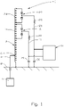
Fig. 1 shows a prior art PIN diode controlled antenna; and -
Fig. 2 shows a switch controlled antenna having calibration equipment according to the present invention. - On the drawings the
reference number 1 denotes a switch controlled antenna that is termed "antenna" in this document. - The
antenna 1 includes a radiatingantenna element 2 that has a connectingline 4 to aradio 5 connected at aline connection 6. Theantenna element 2 is connected to aground plane 8. - A
first switch 10, here in the form of a pair of opposite poled so called PIN diodes, is connected across afirst section 12 of the radiatingelement 2. Biasing voltage for thefirst switch 10 is supplied from acontroller 14 through afirst biasing line 16 through afirst choke 18 to similar elements (cathodes) of the diode pair of thefirst switch 10. Afirst capacitor 20 is connected between thefirst choke 18 and theground plane 8. - Similarly, a
second switch 22, also on the form of a pair of opposite poled PIN diodes, is connected across asecond section 24 of theantenna element 2. Asecond biasing line 26 is connected between thecontroller 14 through asecond choke 28 to similar elements of the diode pair of thesecond switch 22. Asecond capacitor 30 is connected between thesecond choke 28 and theground plane 8. - When a biasing voltage is supplied from the
controller 14 to thefirst switch 10, due to the characteristics of the PIN diodes, the pair of diodes of thefirst switch 10 will remain open in both directions as long as the biasing voltage is present. The pair of diodes of thefirst switch 10 will effectively short circuit thefirst section 12 of theantenna element 2, thus changing the resonant frequency of theantenna element 2. - A biasing voltage supplied to the diode pair of the
second switch 22 will short circuit thesecond section 24 of theantenna element 2. - The operation of a prior art PIN diode controlled antenna is explained in more detail in
US 4,924,238 that is mentioned in the preamble of this document. - Now referring to
fig. 2 , a dottedthird switch 32 indicates that one or more not shown additional switches may be present. - Here, the
connection line 4 is connected to theradio 5 via aselector 33 and a line 4a. Asignal generator 34 is also connected to theconnection line 4 via theselector 33 via a line 36. Thesignal generator 34 is designed to produce radio frequency signals to theantenna element 2. Thesignal generator 34 receives information from thecontroller 14 through a control line 36a of which frequency to produce. - A
directional coupler 38 is designed to read the reflected power fromantenna element 2. Information about the actual reflected power is supplied from thedirectional coupler 38 and to thecontroller 14 through acoupler line 40. - According to this preferred embodiment the
controller 14 includes amain switch 42 that is designed to switch the biasing voltage to the diode pairs of theswitches controller 14 further includes calculatinghardware 44 with appropriate software and is designed to control among other features known to a skilled person, themain switch 42 and thesignal generator 34. - In a first mode of operation, after the
antenna 1 has been installed, and preferable every time theantenna 1 is switched on, the software is initiating a calibration operation. - The calibration operation includes that after the selector has connected the line 36 to the
connection line 4, thecontroller 14 control thesignal generator 34 to produce signal at a first predefined frequency that is supplied to theantenna element 2. At this frequency the diode pairs of thedifferent switches switches - In some cases two or more settings may give more or less equal results. Then the setting giving good results on the widest frequency range may be selected for the table 46.
- The above procedure is repeated for a number of predefined frequencies and the table 46 filled in with values representing the preferred setting at each frequency or frequency range.
- In a second mode of operation, after the
selector 33 has connected the line 4a to theconnection line 4 and when theantenna 1 is in use, thecontroller 14 will bias the diode pairs of theappropriate switches antenna element 2 and the corresponding value in the table 46. The actual frequency at theantenna element 2 may be measured locally or the information supplied by theradio 5, here illustrated by a dottedline 48.
Claims (9)
- A method for calibrating an antenna (1) after installation for field use, wherein at least one switch (10,22,32) is spanning a section (12,24) of a radiating antenna element (2) of the antenna (1), and wherein a controller (14) is configured to selectively close the switch (10,22,32), thus effectively short-circuiting the actual section (12,24) of the antenna element (2), wherein the method includes:- installing the antenna (1) for field use at least for transmission or reception of signals;- then measuring reflected power from the antenna (1) at least for a number of frequencies or frequency ranges at more than one setting of the switch (10,22,32); and- storing for each frequency or frequency range the setting that gives a lowest value of reflected power.
- A method according to claim 1 wherein the method includes measuring the transmission or receiving frequency and set the switch (10,22,32) according to the stored setting.
- A method according to claim 1 wherein the method includes:- providing a signal generator (34) that is controlled by the controller (14) and designed to send radio frequency signals to the antenna (1);- providing a directional coupler (38) at the antenna (1) that is connected to the controller (14); and- measuring the reflected power from the antenna (1) at the directional coupler (38) for a frequency or frequency range produced by the signal generator (34).
- A method according to claim 3 wherein the method includes:- the controller (14) selecting a frequency at the signal generator (34);- the controller (14) selecting a setting of at least the switch (10,22,32); and- measuring and storing the value of reflected power at that frequency and setting.
- A method according to claim 4 wherein the method includes repeating the steps of claim 4 for a number of frequencies or frequency ranges.
- A method according to claim 5 wherein the method includes comparing the values of reflected power for selecting the setting that gives the lowest value of reflected power at the actual frequency or frequency range.
- A method according to claim 6 wherein the method includes making a table of the settings that give the lowest values of reflected power at more than one frequency or frequency range.
- A method according to claim 7 wherein the method includes the controller (14) measuring the actual transmission or receiving frequency or frequency range, or receiving said information from a radio (5), and selecting a setting of the at least one switch (10,22,32) from the table.
- A method according to any of the claims 1 to 8 wherein the method includes providing a directional coupler (38), and the controller (14) with computing hardware and software to cause the controller (14) to execute the method.
Priority Applications (1)
| Application Number | Priority Date | Filing Date | Title |
|---|---|---|---|
| SI201332009T SI2946218T1 (en) | 2013-01-16 | 2013-12-16 | Method and device for calibrating an antenna |
Applications Claiming Priority (2)
| Application Number | Priority Date | Filing Date | Title |
|---|---|---|---|
| US13/743,158 US9442147B2 (en) | 2013-01-16 | 2013-01-16 | Method and device for calibrating an antenna |
| PCT/NO2013/050223 WO2014112880A1 (en) | 2013-01-16 | 2013-12-16 | Method and device for calibrating an antenna |
Publications (3)
| Publication Number | Publication Date |
|---|---|
| EP2946218A1 EP2946218A1 (en) | 2015-11-25 |
| EP2946218A4 EP2946218A4 (en) | 2016-09-28 |
| EP2946218B1 true EP2946218B1 (en) | 2022-07-13 |
Family
ID=51164741
Family Applications (1)
| Application Number | Title | Priority Date | Filing Date |
|---|---|---|---|
| EP13872151.9A Active EP2946218B1 (en) | 2013-01-16 | 2013-12-16 | Method and device for calibrating an antenna |
Country Status (6)
| Country | Link |
|---|---|
| US (1) | US9442147B2 (en) |
| EP (1) | EP2946218B1 (en) |
| KR (1) | KR102041865B1 (en) |
| AU (1) | AU2013374450B2 (en) |
| SI (1) | SI2946218T1 (en) |
| WO (1) | WO2014112880A1 (en) |
Families Citing this family (1)
| Publication number | Priority date | Publication date | Assignee | Title |
|---|---|---|---|---|
| RU2698710C1 (en) * | 2018-04-05 | 2019-08-29 | Федеральное государственное казенное военное образовательное учреждение высшего образования "Военный учебно-научный центр Военно-воздушных сил "Военно-воздушная академия имени профессора Н.Е. Жуковского и Ю.А. Гагарина" (г. Воронеж) Министерства обороны Российской Федерации | Device for measuring reflection coefficient of electromagnetic wave |
Family Cites Families (6)
| Publication number | Priority date | Publication date | Assignee | Title |
|---|---|---|---|---|
| US4011512A (en) * | 1975-05-21 | 1977-03-08 | Motorola, Inc. | Electrical component failure detection apparatus |
| US4924238A (en) | 1987-02-06 | 1990-05-08 | George Ploussios | Electronically tunable antenna |
| US6603810B1 (en) * | 1999-12-30 | 2003-08-05 | Samsung Electronics Co., Ltd. | Combined system for calibrating receiver gain and measuring antenna impedance match and method of operation |
| US7129907B2 (en) * | 2003-10-03 | 2006-10-31 | Sensor Systems, Inc. | Broadband tunable antenna and transceiver systems |
| US20110249760A1 (en) * | 2009-12-21 | 2011-10-13 | Qualcomm Incorporated | Antenna selection based on measurements in a wireless device |
| US8712348B2 (en) * | 2010-09-01 | 2014-04-29 | Samsung Electronics Co., Ltd. | Apparatus and method for controlling a tunable matching network in a wireless network |
-
2013
- 2013-01-16 US US13/743,158 patent/US9442147B2/en active Active
- 2013-12-16 AU AU2013374450A patent/AU2013374450B2/en active Active
- 2013-12-16 KR KR1020157022024A patent/KR102041865B1/en active Active
- 2013-12-16 EP EP13872151.9A patent/EP2946218B1/en active Active
- 2013-12-16 SI SI201332009T patent/SI2946218T1/en unknown
- 2013-12-16 WO PCT/NO2013/050223 patent/WO2014112880A1/en not_active Ceased
Also Published As
| Publication number | Publication date |
|---|---|
| AU2013374450A1 (en) | 2015-08-13 |
| SI2946218T1 (en) | 2022-11-30 |
| KR102041865B1 (en) | 2019-11-27 |
| US9442147B2 (en) | 2016-09-13 |
| EP2946218A4 (en) | 2016-09-28 |
| WO2014112880A1 (en) | 2014-07-24 |
| EP2946218A1 (en) | 2015-11-25 |
| AU2013374450B2 (en) | 2016-07-28 |
| KR20150107839A (en) | 2015-09-23 |
| US20140198000A1 (en) | 2014-07-17 |
Similar Documents
| Publication | Publication Date | Title |
|---|---|---|
| US8395459B2 (en) | Methods for tuning an adaptive impedance matching network with a look-up table | |
| EP3016289A1 (en) | Wireless communication unit, integrated circuit and method for antenna tuning | |
| US7528674B2 (en) | Mobile radio apparatus capable of adaptive impedance matching | |
| EP3068056B1 (en) | Antenna tuning circuit | |
| EP0210746A2 (en) | Impedance matching arrangement | |
| US20080233869A1 (en) | Method and system for a single-chip fm tuning system for transmit and receive antennas | |
| RU2010142017A (en) | ADAPTIVE RETABLE ANTENNAS FOR WIRELESS DEVICES | |
| US9985602B2 (en) | Radio frequency device with compensation of permittivity dispersion of the substrate and adjustment method | |
| EP2751928A1 (en) | Antenna tuning on an impedance trajectory | |
| US11322839B2 (en) | Method and apparatus for implementing reflection type phase shifters (RTPS) in a communication system | |
| EP2273684B1 (en) | Wireless communication apparatus | |
| EP3450999B1 (en) | Methods and apparatuses for testing inductive coupling circuitry | |
| WO2012030157A3 (en) | Apparatus and method for controlling a tunable matching network in a wireless network | |
| US9442147B2 (en) | Method and device for calibrating an antenna | |
| EP3244541B1 (en) | Transmitter efficiency optimization | |
| US20160112070A1 (en) | Antenna module and control method thereof | |
| CN114051696A (en) | Radio frequency transceiver with selectable antenna polarization | |
| WO2015115468A1 (en) | Wireless communication device | |
| JP2007074573A (en) | ANTENNA MATCHING DEVICE, ANTENNA MATCHING METHOD, ANTENNA MATCHING METHOD PROGRAM, AND RECORDING MEDIUM | |
| JP2008288930A (en) | Antenna device | |
| EP3766186A1 (en) | Alignment means for directive antennas | |
| JP5799897B2 (en) | Method of adjusting applied voltage of communication device and matching circuit | |
| JP4990026B2 (en) | Antenna device | |
| JP5657945B2 (en) | Antenna tuning circuit | |
| CN102064771A (en) | Temperature impervious radio device amplifier output power control |
Legal Events
| Date | Code | Title | Description |
|---|---|---|---|
| PUAI | Public reference made under article 153(3) epc to a published international application that has entered the european phase |
Free format text: ORIGINAL CODE: 0009012 |
|
| 17P | Request for examination filed |
Effective date: 20150714 |
|
| AK | Designated contracting states |
Kind code of ref document: A1 Designated state(s): AL AT BE BG CH CY CZ DE DK EE ES FI FR GB GR HR HU IE IS IT LI LT LU LV MC MK MT NL NO PL PT RO RS SE SI SK SM TR |
|
| AX | Request for extension of the european patent |
Extension state: BA ME |
|
| DAX | Request for extension of the european patent (deleted) | ||
| A4 | Supplementary search report drawn up and despatched |
Effective date: 20160831 |
|
| RIC1 | Information provided on ipc code assigned before grant |
Ipc: G01R 29/10 20060101AFI20160825BHEP |
|
| STAA | Information on the status of an ep patent application or granted ep patent |
Free format text: STATUS: EXAMINATION IS IN PROGRESS |
|
| 17Q | First examination report despatched |
Effective date: 20190605 |
|
| REG | Reference to a national code |
Ref country code: DE Ref legal event code: R079 Ref document number: 602013082077 Country of ref document: DE Free format text: PREVIOUS MAIN CLASS: G01R0027060000 Ipc: G01R0029100000 |
|
| GRAP | Despatch of communication of intention to grant a patent |
Free format text: ORIGINAL CODE: EPIDOSNIGR1 |
|
| STAA | Information on the status of an ep patent application or granted ep patent |
Free format text: STATUS: GRANT OF PATENT IS INTENDED |
|
| RIC1 | Information provided on ipc code assigned before grant |
Ipc: H04B 17/12 20150101ALI20220131BHEP Ipc: H04B 17/10 20150101ALI20220131BHEP Ipc: H01Q 1/36 20060101ALI20220131BHEP Ipc: H01Q 9/14 20060101ALI20220131BHEP Ipc: G01R 29/10 20060101AFI20220131BHEP |
|
| INTG | Intention to grant announced |
Effective date: 20220217 |
|
| GRAS | Grant fee paid |
Free format text: ORIGINAL CODE: EPIDOSNIGR3 |
|
| GRAA | (expected) grant |
Free format text: ORIGINAL CODE: 0009210 |
|
| STAA | Information on the status of an ep patent application or granted ep patent |
Free format text: STATUS: THE PATENT HAS BEEN GRANTED |
|
| AK | Designated contracting states |
Kind code of ref document: B1 Designated state(s): AL AT BE BG CH CY CZ DE DK EE ES FI FR GB GR HR HU IE IS IT LI LT LU LV MC MK MT NL NO PL PT RO RS SE SI SK SM TR |
|
| REG | Reference to a national code |
Ref country code: GB Ref legal event code: FG4D |
|
| REG | Reference to a national code |
Ref country code: CH Ref legal event code: EP |
|
| REG | Reference to a national code |
Ref country code: IE Ref legal event code: FG4D |
|
| REG | Reference to a national code |
Ref country code: DE Ref legal event code: R096 Ref document number: 602013082077 Country of ref document: DE |
|
| REG | Reference to a national code |
Ref country code: AT Ref legal event code: REF Ref document number: 1504545 Country of ref document: AT Kind code of ref document: T Effective date: 20220815 |
|
| REG | Reference to a national code |
Ref country code: FI Ref legal event code: FGE |
|
| REG | Reference to a national code |
Ref country code: LT Ref legal event code: MG9D |
|
| REG | Reference to a national code |
Ref country code: NO Ref legal event code: T2 Effective date: 20220713 |
|
| REG | Reference to a national code |
Ref country code: NL Ref legal event code: MP Effective date: 20220713 |
|
| PG25 | Lapsed in a contracting state [announced via postgrant information from national office to epo] |
Ref country code: SE Free format text: LAPSE BECAUSE OF FAILURE TO SUBMIT A TRANSLATION OF THE DESCRIPTION OR TO PAY THE FEE WITHIN THE PRESCRIBED TIME-LIMIT Effective date: 20220713 Ref country code: RS Free format text: LAPSE BECAUSE OF FAILURE TO SUBMIT A TRANSLATION OF THE DESCRIPTION OR TO PAY THE FEE WITHIN THE PRESCRIBED TIME-LIMIT Effective date: 20220713 Ref country code: PT Free format text: LAPSE BECAUSE OF FAILURE TO SUBMIT A TRANSLATION OF THE DESCRIPTION OR TO PAY THE FEE WITHIN THE PRESCRIBED TIME-LIMIT Effective date: 20221114 Ref country code: NL Free format text: LAPSE BECAUSE OF FAILURE TO SUBMIT A TRANSLATION OF THE DESCRIPTION OR TO PAY THE FEE WITHIN THE PRESCRIBED TIME-LIMIT Effective date: 20220713 Ref country code: LV Free format text: LAPSE BECAUSE OF FAILURE TO SUBMIT A TRANSLATION OF THE DESCRIPTION OR TO PAY THE FEE WITHIN THE PRESCRIBED TIME-LIMIT Effective date: 20220713 Ref country code: LT Free format text: LAPSE BECAUSE OF FAILURE TO SUBMIT A TRANSLATION OF THE DESCRIPTION OR TO PAY THE FEE WITHIN THE PRESCRIBED TIME-LIMIT Effective date: 20220713 Ref country code: ES Free format text: LAPSE BECAUSE OF FAILURE TO SUBMIT A TRANSLATION OF THE DESCRIPTION OR TO PAY THE FEE WITHIN THE PRESCRIBED TIME-LIMIT Effective date: 20220713 |
|
| REG | Reference to a national code |
Ref country code: AT Ref legal event code: MK05 Ref document number: 1504545 Country of ref document: AT Kind code of ref document: T Effective date: 20220713 |
|
| PG25 | Lapsed in a contracting state [announced via postgrant information from national office to epo] |
Ref country code: PL Free format text: LAPSE BECAUSE OF FAILURE TO SUBMIT A TRANSLATION OF THE DESCRIPTION OR TO PAY THE FEE WITHIN THE PRESCRIBED TIME-LIMIT Effective date: 20220713 Ref country code: IS Free format text: LAPSE BECAUSE OF FAILURE TO SUBMIT A TRANSLATION OF THE DESCRIPTION OR TO PAY THE FEE WITHIN THE PRESCRIBED TIME-LIMIT Effective date: 20221113 Ref country code: HR Free format text: LAPSE BECAUSE OF FAILURE TO SUBMIT A TRANSLATION OF THE DESCRIPTION OR TO PAY THE FEE WITHIN THE PRESCRIBED TIME-LIMIT Effective date: 20220713 Ref country code: GR Free format text: LAPSE BECAUSE OF FAILURE TO SUBMIT A TRANSLATION OF THE DESCRIPTION OR TO PAY THE FEE WITHIN THE PRESCRIBED TIME-LIMIT Effective date: 20221014 |
|
| REG | Reference to a national code |
Ref country code: DE Ref legal event code: R097 Ref document number: 602013082077 Country of ref document: DE |
|
| PG25 | Lapsed in a contracting state [announced via postgrant information from national office to epo] |
Ref country code: SM Free format text: LAPSE BECAUSE OF FAILURE TO SUBMIT A TRANSLATION OF THE DESCRIPTION OR TO PAY THE FEE WITHIN THE PRESCRIBED TIME-LIMIT Effective date: 20220713 Ref country code: RO Free format text: LAPSE BECAUSE OF FAILURE TO SUBMIT A TRANSLATION OF THE DESCRIPTION OR TO PAY THE FEE WITHIN THE PRESCRIBED TIME-LIMIT Effective date: 20220713 Ref country code: DK Free format text: LAPSE BECAUSE OF FAILURE TO SUBMIT A TRANSLATION OF THE DESCRIPTION OR TO PAY THE FEE WITHIN THE PRESCRIBED TIME-LIMIT Effective date: 20220713 Ref country code: CZ Free format text: LAPSE BECAUSE OF FAILURE TO SUBMIT A TRANSLATION OF THE DESCRIPTION OR TO PAY THE FEE WITHIN THE PRESCRIBED TIME-LIMIT Effective date: 20220713 Ref country code: AT Free format text: LAPSE BECAUSE OF FAILURE TO SUBMIT A TRANSLATION OF THE DESCRIPTION OR TO PAY THE FEE WITHIN THE PRESCRIBED TIME-LIMIT Effective date: 20220713 |
|
| PLBE | No opposition filed within time limit |
Free format text: ORIGINAL CODE: 0009261 |
|
| STAA | Information on the status of an ep patent application or granted ep patent |
Free format text: STATUS: NO OPPOSITION FILED WITHIN TIME LIMIT |
|
| PG25 | Lapsed in a contracting state [announced via postgrant information from national office to epo] |
Ref country code: SK Free format text: LAPSE BECAUSE OF FAILURE TO SUBMIT A TRANSLATION OF THE DESCRIPTION OR TO PAY THE FEE WITHIN THE PRESCRIBED TIME-LIMIT Effective date: 20220713 Ref country code: EE Free format text: LAPSE BECAUSE OF FAILURE TO SUBMIT A TRANSLATION OF THE DESCRIPTION OR TO PAY THE FEE WITHIN THE PRESCRIBED TIME-LIMIT Effective date: 20220713 |
|
| 26N | No opposition filed |
Effective date: 20230414 |
|
| P01 | Opt-out of the competence of the unified patent court (upc) registered |
Effective date: 20230524 |
|
| PG25 | Lapsed in a contracting state [announced via postgrant information from national office to epo] |
Ref country code: AL Free format text: LAPSE BECAUSE OF FAILURE TO SUBMIT A TRANSLATION OF THE DESCRIPTION OR TO PAY THE FEE WITHIN THE PRESCRIBED TIME-LIMIT Effective date: 20220713 |
|
| REG | Reference to a national code |
Ref country code: CH Ref legal event code: PL |
|
| REG | Reference to a national code |
Ref country code: BE Ref legal event code: MM Effective date: 20221231 |
|
| PG25 | Lapsed in a contracting state [announced via postgrant information from national office to epo] |
Ref country code: LU Free format text: LAPSE BECAUSE OF NON-PAYMENT OF DUE FEES Effective date: 20221216 |
|
| PG25 | Lapsed in a contracting state [announced via postgrant information from national office to epo] |
Ref country code: LI Free format text: LAPSE BECAUSE OF NON-PAYMENT OF DUE FEES Effective date: 20221231 Ref country code: IE Free format text: LAPSE BECAUSE OF NON-PAYMENT OF DUE FEES Effective date: 20221216 Ref country code: CH Free format text: LAPSE BECAUSE OF NON-PAYMENT OF DUE FEES Effective date: 20221231 |
|
| PG25 | Lapsed in a contracting state [announced via postgrant information from national office to epo] |
Ref country code: BE Free format text: LAPSE BECAUSE OF NON-PAYMENT OF DUE FEES Effective date: 20221231 |
|
| PG25 | Lapsed in a contracting state [announced via postgrant information from national office to epo] |
Ref country code: HU Free format text: LAPSE BECAUSE OF FAILURE TO SUBMIT A TRANSLATION OF THE DESCRIPTION OR TO PAY THE FEE WITHIN THE PRESCRIBED TIME-LIMIT; INVALID AB INITIO Effective date: 20131216 |
|
| PG25 | Lapsed in a contracting state [announced via postgrant information from national office to epo] |
Ref country code: CY Free format text: LAPSE BECAUSE OF FAILURE TO SUBMIT A TRANSLATION OF THE DESCRIPTION OR TO PAY THE FEE WITHIN THE PRESCRIBED TIME-LIMIT Effective date: 20220713 |
|
| PG25 | Lapsed in a contracting state [announced via postgrant information from national office to epo] |
Ref country code: MK Free format text: LAPSE BECAUSE OF FAILURE TO SUBMIT A TRANSLATION OF THE DESCRIPTION OR TO PAY THE FEE WITHIN THE PRESCRIBED TIME-LIMIT Effective date: 20220713 |
|
| PG25 | Lapsed in a contracting state [announced via postgrant information from national office to epo] |
Ref country code: MC Free format text: LAPSE BECAUSE OF FAILURE TO SUBMIT A TRANSLATION OF THE DESCRIPTION OR TO PAY THE FEE WITHIN THE PRESCRIBED TIME-LIMIT Effective date: 20220713 |
|
| PG25 | Lapsed in a contracting state [announced via postgrant information from national office to epo] |
Ref country code: MC Free format text: LAPSE BECAUSE OF FAILURE TO SUBMIT A TRANSLATION OF THE DESCRIPTION OR TO PAY THE FEE WITHIN THE PRESCRIBED TIME-LIMIT Effective date: 20220713 |
|
| PG25 | Lapsed in a contracting state [announced via postgrant information from national office to epo] |
Ref country code: BG Free format text: LAPSE BECAUSE OF FAILURE TO SUBMIT A TRANSLATION OF THE DESCRIPTION OR TO PAY THE FEE WITHIN THE PRESCRIBED TIME-LIMIT Effective date: 20220713 |
|
| PG25 | Lapsed in a contracting state [announced via postgrant information from national office to epo] |
Ref country code: MT Free format text: LAPSE BECAUSE OF FAILURE TO SUBMIT A TRANSLATION OF THE DESCRIPTION OR TO PAY THE FEE WITHIN THE PRESCRIBED TIME-LIMIT Effective date: 20220713 |
|
| PG25 | Lapsed in a contracting state [announced via postgrant information from national office to epo] |
Ref country code: TR Free format text: LAPSE BECAUSE OF FAILURE TO SUBMIT A TRANSLATION OF THE DESCRIPTION OR TO PAY THE FEE WITHIN THE PRESCRIBED TIME-LIMIT Effective date: 20220713 |
|
| PGFP | Annual fee paid to national office [announced via postgrant information from national office to epo] |
Ref country code: DE Payment date: 20251211 Year of fee payment: 13 |
|
| PGFP | Annual fee paid to national office [announced via postgrant information from national office to epo] |
Ref country code: GB Payment date: 20251210 Year of fee payment: 13 |
|
| PGFP | Annual fee paid to national office [announced via postgrant information from national office to epo] |
Ref country code: NO Payment date: 20251208 Year of fee payment: 13 |
|
| PGFP | Annual fee paid to national office [announced via postgrant information from national office to epo] |
Ref country code: IT Payment date: 20251209 Year of fee payment: 13 Ref country code: FI Payment date: 20251210 Year of fee payment: 13 |
|
| PGFP | Annual fee paid to national office [announced via postgrant information from national office to epo] |
Ref country code: SI Payment date: 20251119 Year of fee payment: 13 |
|
| PGFP | Annual fee paid to national office [announced via postgrant information from national office to epo] |
Ref country code: FR Payment date: 20260115 Year of fee payment: 13 |