EP2945229A1 - Latch assemblies for connector systems - Google Patents
Latch assemblies for connector systems Download PDFInfo
- Publication number
- EP2945229A1 EP2945229A1 EP15167728.3A EP15167728A EP2945229A1 EP 2945229 A1 EP2945229 A1 EP 2945229A1 EP 15167728 A EP15167728 A EP 15167728A EP 2945229 A1 EP2945229 A1 EP 2945229A1
- Authority
- EP
- European Patent Office
- Prior art keywords
- slider
- cartridge
- connector
- cam
- disengage
- Prior art date
- Legal status (The legal status is an assumption and is not a legal conclusion. Google has not performed a legal analysis and makes no representation as to the accuracy of the status listed.)
- Withdrawn
Links
Images




Classifications
-
- H—ELECTRICITY
- H01—ELECTRIC ELEMENTS
- H01R—ELECTRICALLY-CONDUCTIVE CONNECTIONS; STRUCTURAL ASSOCIATIONS OF A PLURALITY OF MUTUALLY-INSULATED ELECTRICAL CONNECTING ELEMENTS; COUPLING DEVICES; CURRENT COLLECTORS
- H01R13/00—Details of coupling devices of the kinds covered by groups H01R12/70 or H01R24/00 - H01R33/00
- H01R13/62—Means for facilitating engagement or disengagement of coupling parts or for holding them in engagement
- H01R13/627—Snap or like fastening
- H01R13/6271—Latching means integral with the housing
- H01R13/6272—Latching means integral with the housing comprising a single latching arm
-
- H—ELECTRICITY
- H01—ELECTRIC ELEMENTS
- H01R—ELECTRICALLY-CONDUCTIVE CONNECTIONS; STRUCTURAL ASSOCIATIONS OF A PLURALITY OF MUTUALLY-INSULATED ELECTRICAL CONNECTING ELEMENTS; COUPLING DEVICES; CURRENT COLLECTORS
- H01R13/00—Details of coupling devices of the kinds covered by groups H01R12/70 or H01R24/00 - H01R33/00
- H01R13/62—Means for facilitating engagement or disengagement of coupling parts or for holding them in engagement
- H01R13/629—Additional means for facilitating engagement or disengagement of coupling parts, e.g. aligning or guiding means, levers, gas pressure electrical locking indicators, manufacturing tolerances
- H01R13/62905—Additional means for facilitating engagement or disengagement of coupling parts, e.g. aligning or guiding means, levers, gas pressure electrical locking indicators, manufacturing tolerances comprising a camming member
- H01R13/62911—U-shaped sliding element
-
- H—ELECTRICITY
- H01—ELECTRIC ELEMENTS
- H01R—ELECTRICALLY-CONDUCTIVE CONNECTIONS; STRUCTURAL ASSOCIATIONS OF A PLURALITY OF MUTUALLY-INSULATED ELECTRICAL CONNECTING ELEMENTS; COUPLING DEVICES; CURRENT COLLECTORS
- H01R13/00—Details of coupling devices of the kinds covered by groups H01R12/70 or H01R24/00 - H01R33/00
- H01R13/62—Means for facilitating engagement or disengagement of coupling parts or for holding them in engagement
- H01R13/629—Additional means for facilitating engagement or disengagement of coupling parts, e.g. aligning or guiding means, levers, gas pressure electrical locking indicators, manufacturing tolerances
- H01R13/62905—Additional means for facilitating engagement or disengagement of coupling parts, e.g. aligning or guiding means, levers, gas pressure electrical locking indicators, manufacturing tolerances comprising a camming member
-
- H—ELECTRICITY
- H01—ELECTRIC ELEMENTS
- H01R—ELECTRICALLY-CONDUCTIVE CONNECTIONS; STRUCTURAL ASSOCIATIONS OF A PLURALITY OF MUTUALLY-INSULATED ELECTRICAL CONNECTING ELEMENTS; COUPLING DEVICES; CURRENT COLLECTORS
- H01R13/00—Details of coupling devices of the kinds covered by groups H01R12/70 or H01R24/00 - H01R33/00
- H01R13/62—Means for facilitating engagement or disengagement of coupling parts or for holding them in engagement
- H01R13/629—Additional means for facilitating engagement or disengagement of coupling parts, e.g. aligning or guiding means, levers, gas pressure electrical locking indicators, manufacturing tolerances
- H01R13/62933—Comprising exclusively pivoting lever
- H01R13/62961—Pivoting lever having extendable handle
-
- H—ELECTRICITY
- H01—ELECTRIC ELEMENTS
- H01R—ELECTRICALLY-CONDUCTIVE CONNECTIONS; STRUCTURAL ASSOCIATIONS OF A PLURALITY OF MUTUALLY-INSULATED ELECTRICAL CONNECTING ELEMENTS; COUPLING DEVICES; CURRENT COLLECTORS
- H01R13/00—Details of coupling devices of the kinds covered by groups H01R12/70 or H01R24/00 - H01R33/00
- H01R13/62—Means for facilitating engagement or disengagement of coupling parts or for holding them in engagement
- H01R13/629—Additional means for facilitating engagement or disengagement of coupling parts, e.g. aligning or guiding means, levers, gas pressure electrical locking indicators, manufacturing tolerances
- H01R13/633—Additional means for facilitating engagement or disengagement of coupling parts, e.g. aligning or guiding means, levers, gas pressure electrical locking indicators, manufacturing tolerances for disengagement only
- H01R13/635—Additional means for facilitating engagement or disengagement of coupling parts, e.g. aligning or guiding means, levers, gas pressure electrical locking indicators, manufacturing tolerances for disengagement only by mechanical pressure, e.g. spring force
-
- H—ELECTRICITY
- H01—ELECTRIC ELEMENTS
- H01R—ELECTRICALLY-CONDUCTIVE CONNECTIONS; STRUCTURAL ASSOCIATIONS OF A PLURALITY OF MUTUALLY-INSULATED ELECTRICAL CONNECTING ELEMENTS; COUPLING DEVICES; CURRENT COLLECTORS
- H01R13/00—Details of coupling devices of the kinds covered by groups H01R12/70 or H01R24/00 - H01R33/00
- H01R13/62—Means for facilitating engagement or disengagement of coupling parts or for holding them in engagement
- H01R13/639—Additional means for holding or locking coupling parts together, after engagement, e.g. separate keylock, retainer strap
-
- H—ELECTRICITY
- H01—ELECTRIC ELEMENTS
- H01R—ELECTRICALLY-CONDUCTIVE CONNECTIONS; STRUCTURAL ASSOCIATIONS OF A PLURALITY OF MUTUALLY-INSULATED ELECTRICAL CONNECTING ELEMENTS; COUPLING DEVICES; CURRENT COLLECTORS
- H01R13/00—Details of coupling devices of the kinds covered by groups H01R12/70 or H01R24/00 - H01R33/00
- H01R13/62—Means for facilitating engagement or disengagement of coupling parts or for holding them in engagement
- H01R13/629—Additional means for facilitating engagement or disengagement of coupling parts, e.g. aligning or guiding means, levers, gas pressure electrical locking indicators, manufacturing tolerances
- H01R13/62977—Pivoting levers actuating linearly camming means
-
- H—ELECTRICITY
- H01—ELECTRIC ELEMENTS
- H01R—ELECTRICALLY-CONDUCTIVE CONNECTIONS; STRUCTURAL ASSOCIATIONS OF A PLURALITY OF MUTUALLY-INSULATED ELECTRICAL CONNECTING ELEMENTS; COUPLING DEVICES; CURRENT COLLECTORS
- H01R13/00—Details of coupling devices of the kinds covered by groups H01R12/70 or H01R24/00 - H01R33/00
- H01R13/62—Means for facilitating engagement or disengagement of coupling parts or for holding them in engagement
- H01R13/629—Additional means for facilitating engagement or disengagement of coupling parts, e.g. aligning or guiding means, levers, gas pressure electrical locking indicators, manufacturing tolerances
- H01R13/633—Additional means for facilitating engagement or disengagement of coupling parts, e.g. aligning or guiding means, levers, gas pressure electrical locking indicators, manufacturing tolerances for disengagement only
- H01R13/6335—Additional means for facilitating engagement or disengagement of coupling parts, e.g. aligning or guiding means, levers, gas pressure electrical locking indicators, manufacturing tolerances for disengagement only comprising a handle
Definitions
- the subject matter herein relates generally to latch assemblies for connector systems.
- Connector systems typically include electrical connectors and mating electrical connectors configured to be mated with corresponding electrical connectors.
- the electrical connectors are part of a backplane.
- the electrical connectors are coupled to the backplane and positioned for mating with the mating electrical connectors.
- the electrical connectors may be mounted to the backplane.
- a need remains for a mechanism to retain an electrical connector to a surface in such a way to create a simple interface.
- a need remains for a tool-less means of attaching electrical connectors to a backplane.
- a connector system which includes a cartridge having at least one cavity configured to hold connector modules therein.
- the cartridge has at least one port therein.
- the cartridge receives the connector modules through the corresponding at least one port.
- the connector system also includes at least one slider latch housed in the cartridge.
- the at least one slider latch is movable in a longitudinal direction and has at least one groove configured to latchably receive a cam of the corresponding connector module to secure the connector modules to the cartridge.
- the at least one slider latch has a biasing member operably coupled thereto. The biasing member biases the at least one slider latch in a biasing direction. The biasing member forces the at least one slider latch to return to a latched position after the cam is received in the profiled groove.
- the connector system also includes at least one disengage slider operably connected to a corresponding slider latch. Movement of the disengage slider forces the slider latch to move from the latched position to a disengage position to release the cam from the corresponding profiled groove to eject each of the connector modules from the cartridge.
- the connector system also includes a discharge mechanism configured to move the discharge slider.
- a connector system which comprises: a cartridge having at least one cavity configured to hold connector modules therein; at least one slider latch housed in the cartridge, the at least one slider latch being movable in a longitudinal direction and having at least one groove configured to receive a cam of a corresponding connector module to secure the connector modules to the cartridge, wherein the at least one slider latch has a biasing member operably coupled thereto, the biasing member biasing the slider latch in a biasing direction, the biasing member forcing the at least one slider latch to return to a latched position after the cam is received in the profiled groove; and a discharge mechanism configured to move a discharge slider.
- a connector system which includes a cartridge having at least one cavity configured to hold connector modules therein.
- the cartridge has at least one port therein.
- the cartridge receives the connector modules through the corresponding at least one port.
- the connector system also includes at least one slider latch housed in the cartridge.
- the at least one slider latch is movable in a longitudinal direction and has at least one groove configured to latchably receive a cam of the corresponding connector module to secure the connector modules to the cartridge.
- the at least one slider latch has a biasing member operably coupled thereto. The biasing member biases the at least one slider latch in a biasing direction. The biasing member forces the at least one slider latch to return to a latched position after the cam is received in the profiled groove.
- the connector system also includes at least one disengage slider operably connected to a corresponding slider latch. Movement of the disengage slider forces the slider latch to move from the latched position to a disengage position to release the cam from the corresponding profiled groove to eject each of the connector modules from the cartridge.
- the connector system also includes a discharge mechanism configured to move the discharge slider.
- a connector system including one or more connector modules having a housing including one or more stations configured to hold a harness key at a plurality of locations.
- the connector system also includes a cartridge having at least one cavity configured to hold connector modules therein.
- the cartridge has at least one port therein.
- the port has a keyway configured to receive the harness key.
- the cartridge receiving the connector modules through the corresponding at least one port.
- the connector system also includes at least one slider latch housed in the cartridge.
- the at least one slider latch is movable in a longitudinal direction and has at least one profiled groove configured to latchably receive a cam of the corresponding connector module to secure the connector modules to the cartridge.
- the at least one slider latch as a biasing member operably coupled thereto.
- the biasing member biasing the at least one slider latch in a biasing direction.
- the biasing member forcing the at least one slider latch to return to a latch position after the cam is received in the profiled groove.
- the connector system also includes at least one disengage slider operably connected to the corresponding slider latch. Movement of the disengage slider forces the slider latch to move from the latched position to a discharge position to release the cam from the corresponding profiled groove to eject each of the connector modules from the cartridge.
- the connector system also includes a discharge mechanism configured to move the discharge slider.
- a connector system including a cartridge having at least one cavity configured to hold connector modules therein.
- the cartridge has at least one port therein.
- the cartridge receives the connector modules through the corresponding at least one port.
- the connector system includes at least one slider latch housed in the cartridge.
- the at least one slider latch is movable in a longitudinal direction and has at least one profiled groove configured to latchably receive a cam of the corresponding connector module to secure the connector module to the cartridge.
- the at least one slider latch has a biasing member operably coupled thereto. The biasing member biasing the at least one slider latch in a biasing direction. The biasing member forcing the at least one slider latch to return to a latched position after the cam is received in the profiled groove.
- the profiled groove includes a latching area in which the cam is captured to secure the connector module.
- the profiled groove includes inclined surfaces to guide the cam into the groove.
- the connector system also includes at least one disengage slider operably connected to a corresponding slider latch. Movement of the disengage slider forces the slider latch to move from the latched position to a discharge position to release the cam from the corresponding profiled groove to eject each of the connector modules form the cartridge.
- the connector system also includes a discharge mechanism configured to move the discharge slider.
- FIG. 1 is a front perspective view of a connector system 100 formed in accordance with an exemplary embodiment.
- the connector system 100 includes a backplane assembly 102 having a cartridge 104 mounted thereto.
- the cartridge 104 is configured to hold at least one connector module 106 therein.
- the connector modules 106 are configured to be electrically connected to corresponding mating electrical connectors (not shown) in the backplane assembly 102 as part of a network system, a server, or other type of system.
- the mating electrical connectors may be part of a daughter card or a printed circuit board (PCB) 108 that is made into the backplane assembly 102.
- PCB printed circuit board
- the backplane assembly 102 includes a plurality of openings 110.
- the cartridge 104 is coupled to the backplane assembly 102 and is used to couple the connector modules 106 to the backplane assembly 102.
- the cartridge 104 may be coupled to the backplane assembly 102 using fasteners (not shown) that extend into and/or through the openings 110.
- the connector modules 106 may be any type of connectors.
- the connector modules 106 may include a plurality of contacts or terminals that are configured to be mated to corresponding contacts or terminals of the mating electrical connectors.
- the contacts or terminals may be terminated directly to the backplane PCB 108 or the daughtercard (not shown) of the backplane assembly 102, such as by surface mounting or through hole mounting to the backplane assembly 102.
- the contacts or terminals may be terminated to ends of wires of the cables of the cable mounted electrical connectors.
- the contacts of terminals may be any types of contacts or terminals, such as pins, sockets, blades, tuning forks, plugs, receptacles, and the like.
- the electrical connectors may be fiber optic connectors in alternative embodiments.
- the cartridge 104 includes at least one cavity 112 configured to hold the connector modules 106 therein.
- the cavity 112 includes at least one port 114 sized and shaped to receive one of the connector modules 106.
- the at least one port 114 is open to the backplane assembly 102 such that the connector modules 106 travel to and through the port 114 to be received in the backplane assembly 102.
- the cavity 112 has four ports 114A, 114B, 114C, and 114D, each holding a corresponding connector module 106A, 106B, 106C, and 106D therein.
- the cavity 112 may include more or fewer ports 114.
- the connector system 100 includes at least one slider latch 116 (also shown in Figure 5 ) housed within the cavity 112 of the cartridge 104.
- the slider latch 116 is movable in a longitudinal direction indicated by the arrows A and B.
- the slider latch 116 secures a portion of the connector module 106 to the cartridge 104 to engage the connector module 106 with the mating electrical connectors in the backplane assembly 102 or daughtercard (not shown).
- At least one disengage slider 118 (also shown in Figure 5 ) is operably connected to the slider latch 116 to eject or disengage the connector module 106 from the cartridge 104.
- the cartridge 104 allows for quick connection and quick disconnection of the connector module 104 form the backplane assembly 102.
- the cartridge 104 may concurrently disengage or eject one or more of the connector modules 106 held in each of the ports 114.
- the connector module 106 is capable of being coupled to the cartridge 104 without the use of threaded fasteners or other types of connectors or fasteners that are time consuming to attach and detach.
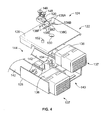
- Figure 2 is a side view of the connector module 106 poised for mounting to the cartridge 104.
- the connector module 106 is aligned with the port 114A and is poised to be inserted into the cavity 112 to be coupled to the cartridge 104.
- the connector module 106 is inserted into the port 114A in a mating direction indicated by the arrow C that is generally perpendicular to the longitudinal movement of the slider latch 116 (shown in Figure 5 ) indicated by the arrows A and B.
- the connector module 106 includes one or more harness keys 120 configured pass through a keyway 150 in the cartridge 104 to allow the connector module 106 to be received in select ports 114.
- Figure 3 is a front perspective view of the connector module 106.
- Figure 4 is an exploded perspective view of the connector module 106.
- the connector module 106 includes a housing 122 having a cavity 124 therein.
- the housing 122 may include a top shell 126 and a bottom shell 128.
- the top and bottom shells 126, 128 may be coupled to one another using a snap-fit and/or other securing means.
- the top shell 126 includes an opening 130 sized and shaped to receive a threaded fastener 132 (shown in Figure 3 ) therethrough.
- the bottom shell 128 includes a threaded receiver 134 (shown in Figure 4 ) that is aligned with the opening 130 and configured to receive the threaded fastener 132.
- the housing 122 may be split along a front shell and a back shell.
- the housing 122 holds a plurality of electrical connectors 136 within the cavity 124. Any number of electrical connectors 136 may be held in the housing 122 depending on the particular application.
- the electrical connectors 136 electrically and mechanically couple to the mating electrical connectors of the backplane assembly 102 (shown in Figure 1 ) when the connector module 106 is mated with the cartridge 104 (shown in Figure 1 ).
- the electrical connectors 136 include mating ends 137 extending beyond a front 140 of the housing 122.
- the mating ends 137 extend into the backplane assembly 102 (shown in Figure 1 ) for mating with the corresponding mating connectors.
- the electrical connectors 136 include cables 142 that extend beyond a back 144 of the housing 122.
- the cables 142 terminate to another electrical device that may be electrically joined to the backplane assembly 102 (shown in Figure 1 ) or daughtercard when the connector module 106 is mated with the cartridge 104 (shown in Figure 1 ).
- the electrical connectors 136 may be configured to carry electrical signals, electrical power, and/or the like.
- cables 142 may be configured as fiber optic cables and the electrical connectors 136 may be configured to carry optical signals.
- the housing 122 includes one or more stations 138 configured to hold the harness key 120.
- the stations 138 allow the harness key 120 to be coupled to the housing 122 at various locations.
- the harness key 120 may be positioned one of the stations 138.
- the harness key 120 may be reconfigurably attached to one of the stations 138 such that the harness key 120 may be removed and replaced in a different station 138.
- the housing 122 includes six stations 138A, 138B, 138C, 138D, 138E, 138F each configured to receive one or more threaded fasteners 148.
- the harness key 120 may be secured to any of the stations 138 using the threaded fasteners 148. As shown in Figure 3 , the harness key 120 is coupled to the station 138F.
- the harness key 120 and stations 138 are shown on the top shell 126, the bottom shell 128 may include a similar arrangement.
- the top shell 126 may include more than one harness key 120 and stations 138.
- the top shell 126 may be sized and shaped differently than the bottom shell 128.
- the one or more harness key 120 and stations 138 may both be held on the top shell 126. In other embodiments, other arrangements are possible.
- the harness key 120 is sized and shaped to be paired with the keyway 150 (shown in Figure 5 ) on the cartridge 104 (shown in Figure 5 ).
- the harness key 120 and the keyway 150 allow a particular connector module 106 to be received only in particular ports 114 (shown in Figure 5 ).
- the harness key 120 and the keyway 150 allow a particular connector module 106 to be mated with a particular port 114 in a predetermined orientation. Accordingly, the connector module 106 may be inserted into the port 114 in a fixed orientation such that the harness key 120 aligns with the keyway 150.
- the harness key 120 may provide guidance during mating and may have a lead-in to facilitate mating.
- the connector module 106 includes cams 152 extending from the housing 122.
- both the top shell 126 and the bottom shell 128 include the cams 152.
- the cams 152 interact with the slider latches 116 (shown in Figure 5 ) to secure the connector modules 106 within the cartridge 104.
- FIG 5 is an exploded perspective view of the cartridge 104.
- the cartridge 104 includes a base mount 154 having the cavity 112 therein.
- the base mount 154 includes an alignment surface 156 thereon.
- the cavity 112 extends through the base mount 154.
- the base mount 154 may have a generally rectangular cross-section.
- the slider latches 116 are housed within cavity 112.
- the slider latches 116 are operably connected to the disengage sliders 118.
- the slider latches 116 and the disengage sliders 118 are movable within the base mount 154 in a longitudinal direction indicated by the arrows A and B along a longitudinal axis 158 of the cartridge 104.
- One or more cartridge spacers 160 may be used to hold the slider latches 116 within the cavity 112. Threaded fasteners 162 extend to and through openings 163 in the base mount 154.
- the alignment surface 156 is part of the base mount 154.
- the alignment surface 156 includes an opening 164 therethrough that provides access to the slider latches 116.
- One or more of the connector module 106 (shown in Figure 1 ) are configured to be loaded into the cartridge 104 through the opening 164.
- the opening 164 includes the ports 114 therein.
- the alignment surface 156 aligns the connector module 106 (shown in Figure 1 ) with the port 114 when the connector module 106 is inserted into the cavity 112.
- the alignment surface 156 includes cutouts 166 in the opening 164.
- the cutouts 166 are configured to receive the corresponding cams 152 (shown in Figure 2 ) therethrough as the connector module 106 is loaded into one of the ports 114 of the base mount 154.
- Each port 114 is configured to receive one of the cartridge assemblies 104.
- Each port 114 includes one or more of the cutouts 166.
- the cutouts 166 are aligned with the cams 152. In the illustrated embodiment, the cutouts 166 are offset across the opening 164. However, in other embodiments, the cutouts 166 may be aligned across the opening 164. Having the cutouts 166 offset provides a way of polarizing the mating of the connector module 106 with the port 114. For example, the cutouts 166 may be positioned such that the connector module 106 may be loaded into the port 114 in only one way.
- the cartridge 104 includes at least one of the keyways 150 at each port 114.
- the keyways 150 include a void 168 sized and shaped to allow the harness key 120 to pass therethrough.
- the void 168 may be positioned along a length of the keyway 150 to correspond to one of the stations 138 (shown in Figure 3 and Figure 4 ).
- the keyways 150A are configured to receive a harness key 120 positioned in the first station 138A (shown in Figure 3 ).
- the keyway 150B is configured to receive a harness key 120 positioned in the fourth station 138D (shown in Figure 3 ).
- the keyways 150C are configured to receive a harness key 120 position in the sixth station 138F (shown in Figure 3 ). In this manner, the keyways 150 are configured to be paired with one of the harness key 120 at one of the stations to govern access to the port 114 by the connector module 106 (shown in Figure 1 ).
- the cartridge 104 includes a discharge mechanism 170 configured to move the disengage sliders 118.
- the discharge mechanism 170 includes an ejector button 172 operably coupled to the disengage sliders 118 to move the disengage sliders 118 along the longitudinal axis 158 when the ejector button 172 is pressed.
- the ejector button 172 has an actuation end 174 that is configured to be located outside of the base mount 154 to be pressed by an operator to release the slider latch 116.
- the ejector button 172 may be pressed in the direction indicated by the arrow B along the longitudinal axis 158 to move the disengage sliders 118 form a latched position to a discharge position to eject the connector module 106 (shown in Figure 1 ).
- the cartridge 104 retains the connector module 106 (shown in Figure 1 ).
- the cartridge 104 provides a simple interface for securing the connector module 106 within one of the ports 114 and ejecting the connector module 106 on demand.
- the cartridge 104 secures the connector module 106 without the need for tools or separate fasteners.
- the cartridge 104 can be operated with one hand to eject the connector module 106.
- the cartridge 104 can be actuated to concurrently eject a plurality of the connector modules 106 held in each port 114.
- the cartridge 104 is narrow and allows the connector modules to be stacked side by side in a tight pitch.
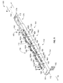
- FIG 6 is a perspective view of a slider sub-assembly 180.
- the slider sub-assembly 180 includes the slider latches 116, the disengage sliders 118, the discharge mechanism 170, and one of the cartridge spacers 160, among other components.
- the slide sub-assembly 180 may be housed in the cavity 112 (shown in Figure 5 ) of the cartridge 104 (shown in Figure 5 ).
- the disengage sliders 118A, 118B extends along opposite sides of the slider sub-assembly 180.
- the disengage sliders 118 may be stamped and formed structures that are joined to one another.
- the cartridge spacer 160 joins the disengage sliders 118 to one another at a distal end 181.
- the disengage sliders 118 are operably coupled to the discharge mechanism 170 at a proximal end 183. Thus, the disengage sliders 118 move at the same time when the discharge mechanism 170 is activated.
- the disengage sliders 118 are coupled to each of the slider latches 116 such that the disengage sliders 118 force each of the slider latches 116 to move from a latched position to a discharge position to eject each of the connector modules 106 (shown in Figure 1 ).
- Each of the slider latches 116 has a profiled groove 182 configured to latchably receive the cam 152 (shown in Figure 3 ) of the connector module 106 (shown in Figure 3 ) to secure the connector module 106 to the cartridge 104 (shown in Figure 5 ).
- Each of the slider latches 116 also has a biasing member 184 biasing the corresponding slider latch 116 in a biasing direction indicated by the arrow A along the longitudinal axis 158. The biasing member 184 forces the slider latch 116 to return to the latched position after the cam 152 (shown in Figure 3 ) is received in the profiled groove 182.
- the disengage sliders 118 cause the cam 152 to be released from the profiled groove 182 when the disengage sliders 118 are caused to move.
- the disengage sliders 118 are operably coupled to the ejector button 172.
- a return spring 173 is coupled to the ejector button 172 and abuts the cartridge spacer 160 (shown in Figure 5 ) at the proximal end 183. The return spring 173 applies a bias force on the disengage sliders 118 to return the disengage sliders 118 to the latched position, as discussed below.
- Figure 7 is an enlarged perspective view of one of the slider latches 116 and the disengage slider 118.
- the slider latch 116 is coupled to the disengage slider 118 such that the slider latch 116 may move independently of the disengage slider 118.
- the disengage slider 118 includes a first channel 188 configured to receive a tail portion 190 of the slider latch 116.
- the first channel 188 receives the tail portion 190 in a dove-tail arrangement.
- the first channel 188 allows the tail portion 190, and hence the slider latch 116, to translate in the direction of the longitudinal axis 158.
- a contact surface 192 on the disengage slider 118 abuts a stopper 194 on the slider latch 116 to limit the movement of the slider latch 116 in the direction along the longitudinal axis 158 indicated by the arrow A.
- the connector module 106 and the cartridge 104 may create or provide an indication when the cam 152 is secured and captured in the profiled groove 182.
- the stopper 194 is configured to produce an audible indication when the stopper 194 contacts the contact surface 192 to indicate that the cam 152 is secured in the profiled groove 182.
- other components may produce the audible indication.
- the cartridge 104 and connector module 106 may provide a visual indication.
- the housing 122 may include a marking that is covered or hidden by the alignment surface 156 when the connector module 106 is secured within the cartridge 104. Indicators may be provided when the connector module 106 is unlocked, unlatched and/or removed.
- the biasing member 184 applies a biasing force on the slider latch 116 in the direction A.
- the biasing member 184 abuts a rear surface 196 of the slider latch 116.
- the biasing member 184 includes a tail portion 198 received in a second channel 200 of the disengage slider 118.
- the first and second channels 188, 200 allow the biasing member 184 and the slider latch 116 to be held in place in the disengage slider 118 while the slider sub-assembly 180 is assembled and/or inserted into cartridge 104 (shown in Figure 5 ).
- Figure 8 is a side cross-sectional view of the cam 152 engaging the slider latch 116.
- Figure 9 is a side cross-sectional view of the slider latch 116 capturing the cam 152.
- Figures 8 and 9 illustrate the interaction of the cam 152, the slider latch 116, and the disengage slider 118.
- the cam 152 includes a profiled cam surface 230.
- the profiled cam surface 230 has a plurality of flat surfaces that are angled with respect to one another.
- the angled surfaces are angled at non-orthogonal angles. The angled surfaces correspond to surfaces of the profiled groove 182 to control movement of the cam 152 along the profiled grooves 182 as the connector module 106 is being plugged into the cartridge 104 and as the connector module 106 is being ejected from the cartridge 104.
- the cam 152 includes a first inclined surface 232, a second inclined surface 234, and third inclined surface 236 and a fourth inclined surface 238.
- the cam 152 may include other inclined surfaces in addition to the incline surfaces 232-238.
- the inclined surfaces 232-238 are configured to engage different portions of the profiled groove 182 as the slider latch 116 is moved between the latched position and the discharge position.
- the profiled grove 182 includes a plurality of inclined surfaces that are configured to guide the cam 152 into and out of the cavity 112. However, in other embodiments, the profiled groove 182 may not include the inclined surfaces.
- the connector module 106 and cam 152 move linearly along a plug/unplug axis 240 while the slider latch 116 moves linearly along the longitudinal axis 158.
- the cam 152 drives the slider latch 116 along the longitudinal axis 158 in the direction B.
- the slider latch 116 is moved along the longitudinal axis 158 in the direction A to drive the cam 152 out of the cavity 112.
- the profiled groove 182 includes a first inclined surface 242, a second inclined surface 244, and third inclined surface 246, and a fourth inclined surface 248.
- the disengage slider 118 (best shown in Figure 7 ) also includes the inclined surfaces 242-248 that follow the contour of the inclined surfaces 242-248 on the slider latch 116.
- the first inclined surface 232 of the cam 152 is configured to interact with the first inclined surface 242 of the profiled grove 182.
- the second inclined surface 234 interacts with the second inclined surface 244, the third inclined surface 236 interacts with the third inclined surface 246 and the fourth inclined surface 238 interacts with the fourth inclined surface 248.
- the first inclined surfaces 232, 242 have similar angles.
- the second inclined surfaces 234, 244 have similar angles; the third inclined surfaces 236, 246 have similar angles; and the fourth inclined surfaces 238, 248 have similar angles.
- the cam 152 is loaded through the cutouts 166 until the cam 152 engages the slider latch 116.
- the first inclined surface 232 engages the first inclined surface 242.
- the cam 152 slides along the profiled grooves 182.
- the cam 152 drives the slider latch 116 to a clearance position at which the cam 152 clears a blocker 220.
- the cam 152 is then loaded into a latching area 250 of the corresponding profiled grooves 182.
- the latching area 250 is located under the blocker 220.
- the latching area 250 is defined, at least in part by the second inclined surface 244 of the profiled groove 182.
- the second inclined surface 244 has a slight angle 252 with respect to the longitudinal axis 158, such as approximately 10°.
- the angle 252 of the second inclined surface 244 helps draw the connector module 106 into the cartridge 104.
- the second inclined surface 244 forces the cam 152 downward as the slider latch 116 is driven to the latched or resting position.
- the cam 152 may provide an audible indication when the cam is 152 secured within the profiled groove 182.
- the discharge mechanism 170 (shown in Figure 5 ) is caused to move in the direction B, which drives the slider latch 116 from the latched or resting position to the discharge position.
- the third inclined surface 246 is driven into the third inclined surface 236 of the cam 152.
- the cam 152 slides along the profiled groove 182.
- the cam 152 and the connector module 106 are driven outward (e.g. in an upward direction).
- the cam 152 is driven to a holding area 254 of the profiled groove 182. In the holding area 254, the cam has not been fully ejected.
- the cam 152 is clear of the blocker 220 in the holding area 254 and the connector module 106 can be manually pulled out of the cartridge 104.
- the cam 152 is driven to the holding area 254 when the discharge mechanism 170 is fully driven.
- the cam 152 is in the holding area 254 and is no longer blocked by the blocker 220.
- the slider latch 116 is forced in the direction B by the discharge mechanism 170.
- the stopper 194 abuts the contact surface 192 (both shown in Figure 8 ) creating an audible indication.
- the blocker 220 engages the cam 152.
- the blocker 220 is positioned inward of the holding area 254 to ensure that the cam 152 does not move back into the latching area 250, but rather is moved into an ejection area 256 and ultimately is ejected out of the cavity 112.
- the profiled groove first inclined surface 242 engages the cam first inclined surface 232.
- the blocker 220 forces the cam 152 outward and fully ejects the cam from the cavity 112.
- the ejection is a two stage ejection process. The first stage is accomplished with moving the slider latch 116 from the latched or resting position to the discharge position. The second stage is accomplished when the slider latch 116 moves from the discharge position to the latched position.
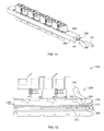
- FIG 10 is a top view of the cartridge 104 having an electrical discharge mechanism 260.
- the cartridge 104 is shown with the top shell 126 (shown in Figure 5 ) removed.
- the discharge mechanism 170 (shown in Figure 5 ) is configured as an electrical discharge mechanism (EDM) 260.
- the discharge mechanism 170 does not include the ejector button 172 (shown in Figure 5 ). Instead, an electrical motor module 262 is coupled to the disengage sliders 118.
- EDM 260 Such a discharge mechanism 170 is referred to herein as the EDM 260.
- the electrical motor module 262 is configured to cause the disengage sliders 118 to move to eject the connector modules 106 from the cartridge 104.
- the EDM 260 includes a jackscrew 264 coupled to a driver bar 268.
- the driver bar 268 extends laterally generally perpendicular to the longitudinal axis 158 and is coupled to the disengage sliders 118 on opposite sides of the opening 164.
- the driver bar 268 moves along the longitudinal axis 158.
- the jackscrew 264 causes the driver bar 268, and hence the disengage sliders 118 to move. Accordingly, the disengage sliders 118 may be caused to move from the discharge position to the latched position and vice versa.
- the electrical motor module 262 is configured to drive the jackscrew 264.
- the electrical motor module 262 is powered using direct current (DC), however, in other embodiments, the electrical motor module 262 may be powered using alternating current (AC).
- DC direct current
- AC alternating current
- the EDM 260 may include at least one limit switch 270.
- the EDM 260 includes limit switches 270A and 270B.
- the limit switches 270 may be any type of switches capable of being triggered or actuated when a portion of the disengage sliders 118 abuts the switch contact.
- the limit switches 270 may be spring-loaded momentary switches.
- the limit switch 270A is configured to actuate when the disengage sliders 118 reach the latched position.
- the limit switch 270B is configured to actuate when the disengage sliders 118 reach the discharge position.
- the electrical motor module 262 may drive the jackscrew 264 to cause the disengage sliders 118 to move. For example, the electrical motor module 262 may cause the disengage sliders 118 to move in the direction B until the disengage sliders 118 actuate the limit switch 270A. Similarly, the electrical motor module 262 may cause the disengage sliders 118 to move in the direction A until the disengage sliders 118 actuate the limit switch 270B. In other embodiments, other position detection components may be used. For example, optical sensors may be used to determine the position of the disengage sliders 118.
- the EDM includes a control box 272 having a control interface 274 configured to energize the electrical motor module 262 on demand.
- the control interface 274 may be used to eject the connector modules 106 (shown in Figure 1 ) when a button 276 is pressed.
- the control box 272 may be communicatively coupled to the electrical motor module 262 via a wireless link 278, but in other embodiments other links may be used, such as a wired link.
- the control interface 274 may include at least one indicator status lights 280.
- the indicator status lights 280 may be illuminated when electrical motor module 262 is being driven.
- the control box 272 may be embodied as a computing device, a mobile device and/or the like.
- the mobile device may be a mobile phone, mobile computer and/or the like.
- FIG 11 is a perspective view of the cartridge 104 having a manually rotatable discharge mechanism 286.
- the discharge mechanism 286 may be configured to prevent tampering or inadvertent activation.
- the discharge mechanism 286 may have a button configured to be locked or guarded to prevent the button from being depressed.
- the discharge mechanism 170 (shown in Figure 5 ) is configured to be actuated using an external driver tool 282.
- the discharge mechanism 170 does not include the ejector button 172 (shown in Figure 5 ), or the electrical motor module 262 (shown in Figure 10 ).
- Such a discharge mechanism 170 is referred to herein as the manual discharge mechanism 286.
- the manual discharge mechanism 286 includes the jackscrew 264 (shown in Figure 10 ) and the driver bar 268 (shown in Figure 10 ).
- the jackscrew 264 is operably coupled to a driver head 290 instead of the electrical motor module 262 (shown in Figure 10 ).
- a face of the driver head 290 extends through an opening 191 in the base mount 154.
- the driver head 290 is configured to be driven by the driver tool 282.
- the driver head 290 and the driver tool 282 may be complementary to one another.
- the driver head 290 may have a depression configured to receive a portion of the driver tool 282.
- the driver tool 282 and the driver head 290 have a selective pattern such that the driver head 290 will only receive, and is only compatible with the driver tool 282.
- the manual discharge mechanism 286 may prevent unauthorized or inadvertent ejection of the connector modules 106 (shown in Figure 3 ).
- the driver tool 282 is manually rotated to cause the driver head 290, and hence the jackscrew 264 to rotate.
- the jackscrew 264 causes the driver bar 268, and hence the disengage sliders 118 to move. Accordingly, the disengage sliders 118 may be caused to move from the discharge position to the latched position and vice versa.
- FIG 12 is a cross-sectional side view of the cartridge 104 having a levered discharge mechanism 298.
- the discharge mechanism 170 (shown in Figure 5 ) is configured to be actuated by rotating a handle 300.
- the discharge mechanism 170 does not include the ejector button 172 (shown in Figure 5 ).
- Such a discharge mechanism 170 is referred to herein as the levered discharge mechanism 298.
- the handle 300 includes a pivot axle 302 coupled to opposite sides of the base mount 154.
- the handle 300 is free to rotate or pivot about the pivot axle 302.
- the handle 300 includes a geared portion 304 circumferentially surrounding the pivot axle 302.
- the handle 300 includes the geared portion 304 on both sides of the pivot axle 302.
- the geared portions 304 are configured to engage linear gear portions 308 on a portion of each disengage slider 310.
- the linear gear portions 308 include teeth 312 having a similar pitch as the geared portions 304 such that when the geared portions 304 are caused to rotate, the linear gear portions 308 move longitudinally in the direction of the longitudinal axis 158.
- the handle 300 may be rotated to cause the disengage sliders 310 to move from the resting position to the discharge position and vice versa.
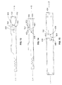
- Figure 13 is a side view of a disengage slider 400 having a profiled groove 402.
- the slider latch 116 (shown in Figure 5 ) is integrally formed with the disengage slider 400.
- the connector system 100 does not include a separate slider latch 116.
- the disengage slider 400 is configured to engage the cam 152 (also shown in Figure 3 ) to secure the connector module 106 (shown in Figure 1 ) to the cartridge 104 (shown in Figure 1 ).
- the profiled groove 402 does not include the inclined surfaces 232-238 (shown in Figure 9 ). Instead the profiled groove 402 includes a vertical slot 404 and a horizontal slot 408.
- the cam 152 is received in the vertical slot 404 and travels along the vertical slot 404 to a staging position 410 at the bottom of the vertical slot 404.
- the disengage slider 400 is caused to be moved in the direction B to cause the cam 152 to travel into and along the horizontal slot 408.
- the cam 152 is then held in the horizontal slot 408 to secure the connector module 106 to the cartridge 104.
- the disengage slider 400 is moved in the direction A until the cam 152 is then moved to staging position 410.
- the connector module 106 is the pulled or removed from the cartridge 104.
- Figure 14 is a side view of a disengage slider 420 configured to eject the connector module 106 (shown in Figure 1 ).
- the slider latch 116 (shown in Figure 5 ) is integrally formed with the disengage slider 400.
- the disengage slider 420 includes an upper inclined surface 422 and a lower inclined surface 424 both extending between the vertical slot 404 and the horizontal slot 408.
- the cam 152 is received in the vertical slot 404 and travels along the vertical slot 404 to a staging position 426.
- the disengage slider 420 is then moved in the direction B to cause the cam 152 to slide along the upper inclined surface 422 which pulls the connector module 106 downward into the cartridge 104 (shown in Figure 1 ).
- the disengage slider 420 is moved in the direction A.
- the cam 152 exits the horizontal slot 408 and slides along the lower inclined surface 424. As such, the disengage slider 420 lifts the connector module 106 out of the cartridge 104.
- Figure 15 is a side view of a disengage slider 430 having a blocker 432.
- the slider latch 116 (shown in Figure 5 ) is integrally formed with the disengage slider 430.
- the disengage slider 430 include a profiled groove 434 having inclined surfaces 436 and 438.
- the disengage slider 430 may be spring loaded or biased in the direction B.
- the cam 152 slides along the inclined surface 436.
- the disengage slider 430 moves in the direction A as the cam 152 slides along the inclined surface 436.
- the cam 154 is then loaded in a latching area 440 under the blocker 432.
- the disengage slider is caused to be moved in the direction A.
- the cam 152 slides along the inclined surface 438 to lift the connector module 106 out of the cartridge 104.
Landscapes
- Details Of Connecting Devices For Male And Female Coupling (AREA)
Abstract
Description
- The subject matter herein relates generally to latch assemblies for connector systems.
- Connector systems typically include electrical connectors and mating electrical connectors configured to be mated with corresponding electrical connectors. In some applications, the electrical connectors are part of a backplane. The electrical connectors are coupled to the backplane and positioned for mating with the mating electrical connectors. The electrical connectors may be mounted to the backplane.
- Current retention methods include designs with screws that secure the electrical connectors to the backplane. Such retention methods require tools to assemble and unassemble, which is time consuming. Also, loosening of the screws due to vibration is another potential problem. Other retention methods introduce release mechanisms to secure the electrical connectors to the backplane. But those retention methods typically allow a single module to be connected or released from the backplane at a time.
- A need remains for a mechanism to retain an electrical connector to a surface in such a way to create a simple interface. A need remains for a tool-less means of attaching electrical connectors to a backplane.
- According to one aspect of the present invention, a connector system is provided which includes a cartridge having at least one cavity configured to hold connector modules therein. The cartridge has at least one port therein. The cartridge receives the connector modules through the corresponding at least one port. The connector system also includes at least one slider latch housed in the cartridge. The at least one slider latch is movable in a longitudinal direction and has at least one groove configured to latchably receive a cam of the corresponding connector module to secure the connector modules to the cartridge. The at least one slider latch has a biasing member operably coupled thereto. The biasing member biases the at least one slider latch in a biasing direction. The biasing member forces the at least one slider latch to return to a latched position after the cam is received in the profiled groove. The connector system also includes at least one disengage slider operably connected to a corresponding slider latch. Movement of the disengage slider forces the slider latch to move from the latched position to a disengage position to release the cam from the corresponding profiled groove to eject each of the connector modules from the cartridge. The connector system also includes a discharge mechanism configured to move the discharge slider.
- According to another aspect of the present invention, a connector system is provided which comprises: a cartridge having at least one cavity configured to hold connector modules therein; at least one slider latch housed in the cartridge, the at least one slider latch being movable in a longitudinal direction and having at least one groove configured to receive a cam of a corresponding connector module to secure the connector modules to the cartridge, wherein the at least one slider latch has a biasing member operably coupled thereto, the biasing member biasing the slider latch in a biasing direction, the biasing member forcing the at least one slider latch to return to a latched position after the cam is received in the profiled groove; and a discharge mechanism configured to move a discharge slider.
- The invention will now be described by way of example with reference to the accompanying drawings in which:
-
Figure 1 is a front perspective view of a connector system formed in accordance with an embodiment; -
Figure 2 is a side view of a connector module poised for mounting to a cartridge formed in accordance with an embodiment; -
Figure 3 is a front perspective view of a connector module formed in accordance with an embodiment; -
Figure 4 is an exploded perspective view of a connector module formed in accordance with an embodiment; -
Figure 5 is an exploded perspective view of a cartridge formed in accordance with an embodiment; -
Figure 6 is a perspective view of a slider sub-assembly formed in accordance with an embodiment; -
Figure 7 is an enlarged perspective view of a slider latch and a disengage slider formed in accordance with an embodiment; -
Figure 8 is a side cross-sectional view of a cam engaging a slider latch formed in accordance with an embodiment; -
Figure 9 is a side cross-sectional view of a slider latch capturing a cam formed in accordance with an embodiment; -
Figure 10 is a top view of a cartridge having an electrical discharge mechanism formed in accordance with an embodiment; -
Figure 11 is a perspective view of a cartridge having a manually rotatable discharge mechanism formed in accordance with an embodiment; -
Figure 12 is a cross-sectional side view of a cartridge having a levered discharge mechanism formed in accordance with an embodiment; -
Figure 13 is a side view of a disengage slider having a profiled groove formed in accordance with an embodiment; -
Figure 14 is a side view of a disengage slider configured to eject a connector module formed in accordance with an embodiment; and -
Figure 15 is a side view of a disengage slider having a blocker formed in accordance with an embodiment. - In one embodiment, a connector system is provided which includes a cartridge having at least one cavity configured to hold connector modules therein. The cartridge has at least one port therein. The cartridge receives the connector modules through the corresponding at least one port. The connector system also includes at least one slider latch housed in the cartridge. The at least one slider latch is movable in a longitudinal direction and has at least one groove configured to latchably receive a cam of the corresponding connector module to secure the connector modules to the cartridge. The at least one slider latch has a biasing member operably coupled thereto. The biasing member biases the at least one slider latch in a biasing direction. The biasing member forces the at least one slider latch to return to a latched position after the cam is received in the profiled groove. The connector system also includes at least one disengage slider operably connected to a corresponding slider latch. Movement of the disengage slider forces the slider latch to move from the latched position to a disengage position to release the cam from the corresponding profiled groove to eject each of the connector modules from the cartridge. The connector system also includes a discharge mechanism configured to move the discharge slider.
- In another embodiment, a connector system is provided including one or more connector modules having a housing including one or more stations configured to hold a harness key at a plurality of locations. The connector system also includes a cartridge having at least one cavity configured to hold connector modules therein. The cartridge has at least one port therein. The port has a keyway configured to receive the harness key. The cartridge receiving the connector modules through the corresponding at least one port. The connector system also includes at least one slider latch housed in the cartridge. The at least one slider latch is movable in a longitudinal direction and has at least one profiled groove configured to latchably receive a cam of the corresponding connector module to secure the connector modules to the cartridge. The at least one slider latch as a biasing member operably coupled thereto. The biasing member biasing the at least one slider latch in a biasing direction. The biasing member forcing the at least one slider latch to return to a latch position after the cam is received in the profiled groove. The connector system also includes at least one disengage slider operably connected to the corresponding slider latch. Movement of the disengage slider forces the slider latch to move from the latched position to a discharge position to release the cam from the corresponding profiled groove to eject each of the connector modules from the cartridge. The connector system also includes a discharge mechanism configured to move the discharge slider.
- In another embodiment, a connector system is provided including a cartridge having at least one cavity configured to hold connector modules therein. The cartridge has at least one port therein. The cartridge receives the connector modules through the corresponding at least one port. The connector system includes at least one slider latch housed in the cartridge. The at least one slider latch is movable in a longitudinal direction and has at least one profiled groove configured to latchably receive a cam of the corresponding connector module to secure the connector module to the cartridge. The at least one slider latch has a biasing member operably coupled thereto. The biasing member biasing the at least one slider latch in a biasing direction. The biasing member forcing the at least one slider latch to return to a latched position after the cam is received in the profiled groove. The profiled groove includes a latching area in which the cam is captured to secure the connector module. The profiled groove includes inclined surfaces to guide the cam into the groove. The connector system also includes at least one disengage slider operably connected to a corresponding slider latch. Movement of the disengage slider forces the slider latch to move from the latched position to a discharge position to release the cam from the corresponding profiled groove to eject each of the connector modules form the cartridge. The connector system also includes a discharge mechanism configured to move the discharge slider.
-
Figure 1 is a front perspective view of aconnector system 100 formed in accordance with an exemplary embodiment. Theconnector system 100 includes abackplane assembly 102 having acartridge 104 mounted thereto. Thecartridge 104 is configured to hold at least oneconnector module 106 therein. Theconnector modules 106 are configured to be electrically connected to corresponding mating electrical connectors (not shown) in thebackplane assembly 102 as part of a network system, a server, or other type of system. For example, the mating electrical connectors may be part of a daughter card or a printed circuit board (PCB) 108 that is made into thebackplane assembly 102. - The
backplane assembly 102 includes a plurality ofopenings 110. Thecartridge 104 is coupled to thebackplane assembly 102 and is used to couple theconnector modules 106 to thebackplane assembly 102. Thecartridge 104 may be coupled to thebackplane assembly 102 using fasteners (not shown) that extend into and/or through theopenings 110. - The
connector modules 106 may be any type of connectors. Theconnector modules 106 may include a plurality of contacts or terminals that are configured to be mated to corresponding contacts or terminals of the mating electrical connectors. The contacts or terminals may be terminated directly to thebackplane PCB 108 or the daughtercard (not shown) of thebackplane assembly 102, such as by surface mounting or through hole mounting to thebackplane assembly 102. Alternatively, the contacts or terminals may be terminated to ends of wires of the cables of the cable mounted electrical connectors. The contacts of terminals may be any types of contacts or terminals, such as pins, sockets, blades, tuning forks, plugs, receptacles, and the like. The electrical connectors may be fiber optic connectors in alternative embodiments. - The
cartridge 104 includes at least onecavity 112 configured to hold theconnector modules 106 therein. Thecavity 112 includes at least oneport 114 sized and shaped to receive one of theconnector modules 106. The at least oneport 114 is open to thebackplane assembly 102 such that theconnector modules 106 travel to and through theport 114 to be received in thebackplane assembly 102. In the illustrated embodiment, thecavity 112 has fourports corresponding connector module cavity 112 may include more orfewer ports 114. - The
connector system 100 includes at least one slider latch 116 (also shown inFigure 5 ) housed within thecavity 112 of thecartridge 104. Theslider latch 116 is movable in a longitudinal direction indicated by the arrows A and B. Theslider latch 116 secures a portion of theconnector module 106 to thecartridge 104 to engage theconnector module 106 with the mating electrical connectors in thebackplane assembly 102 or daughtercard (not shown). At least one disengage slider 118 (also shown inFigure 5 ) is operably connected to theslider latch 116 to eject or disengage theconnector module 106 from thecartridge 104. In an exemplary embodiment, thecartridge 104 allows for quick connection and quick disconnection of theconnector module 104 form thebackplane assembly 102. For example, thecartridge 104 may concurrently disengage or eject one or more of theconnector modules 106 held in each of theports 114. As such, theconnector module 106 is capable of being coupled to thecartridge 104 without the use of threaded fasteners or other types of connectors or fasteners that are time consuming to attach and detach. -
Figure 2 is a side view of theconnector module 106 poised for mounting to thecartridge 104. As illustrated, theconnector module 106 is aligned with theport 114A and is poised to be inserted into thecavity 112 to be coupled to thecartridge 104. Theconnector module 106 is inserted into theport 114A in a mating direction indicated by the arrow C that is generally perpendicular to the longitudinal movement of the slider latch 116 (shown inFigure 5 ) indicated by the arrows A and B. As is discussed below, theconnector module 106 includes one ormore harness keys 120 configured pass through akeyway 150 in thecartridge 104 to allow theconnector module 106 to be received inselect ports 114. -
Figure 3 is a front perspective view of theconnector module 106.Figure 4 is an exploded perspective view of theconnector module 106. - The
connector module 106 includes ahousing 122 having acavity 124 therein. Thehousing 122 may include atop shell 126 and abottom shell 128. The top andbottom shells top shell 126 includes anopening 130 sized and shaped to receive a threaded fastener 132 (shown inFigure 3 ) therethrough. Thebottom shell 128 includes a threaded receiver 134 (shown inFigure 4 ) that is aligned with theopening 130 and configured to receive the threadedfastener 132. In other embodiments, other arrangements are possible. For example, thehousing 122 may be split along a front shell and a back shell. - The
housing 122 holds a plurality ofelectrical connectors 136 within thecavity 124. Any number ofelectrical connectors 136 may be held in thehousing 122 depending on the particular application. Theelectrical connectors 136 electrically and mechanically couple to the mating electrical connectors of the backplane assembly 102 (shown inFigure 1 ) when theconnector module 106 is mated with the cartridge 104 (shown inFigure 1 ). Theelectrical connectors 136 include mating ends 137 extending beyond afront 140 of thehousing 122. The mating ends 137 extend into the backplane assembly 102 (shown inFigure 1 ) for mating with the corresponding mating connectors. Theelectrical connectors 136 includecables 142 that extend beyond a back 144 of thehousing 122. In an exemplary embodiment, thecables 142 terminate to another electrical device that may be electrically joined to the backplane assembly 102 (shown inFigure 1 ) or daughtercard when theconnector module 106 is mated with the cartridge 104 (shown inFigure 1 ). In certain embodiments, theelectrical connectors 136 may be configured to carry electrical signals, electrical power, and/or the like. In other embodiments,cables 142 may be configured as fiber optic cables and theelectrical connectors 136 may be configured to carry optical signals. - The
housing 122 includes one or more stations 138 configured to hold theharness key 120. The stations 138 allow theharness key 120 to be coupled to thehousing 122 at various locations. Theharness key 120 may be positioned one of the stations 138. Theharness key 120 may be reconfigurably attached to one of the stations 138 such that theharness key 120 may be removed and replaced in a different station 138. In the illustrated embodiment, thehousing 122 includes sixstations fasteners 148. Theharness key 120 may be secured to any of the stations 138 using the threadedfasteners 148. As shown inFigure 3 , theharness key 120 is coupled to thestation 138F. In other embodiments, other securing means may be used. Although theharness key 120 and stations 138 are shown on thetop shell 126, thebottom shell 128 may include a similar arrangement. Optionally, thetop shell 126 may include more than oneharness key 120 and stations 138. For example, thetop shell 126 may be sized and shaped differently than thebottom shell 128. The one ormore harness key 120 and stations 138 may both be held on thetop shell 126. In other embodiments, other arrangements are possible. - The
harness key 120 is sized and shaped to be paired with the keyway 150 (shown inFigure 5 ) on the cartridge 104 (shown inFigure 5 ). In an exemplary embodiment, theharness key 120 and thekeyway 150 allow aparticular connector module 106 to be received only in particular ports 114 (shown inFigure 5 ). Optionally, theharness key 120 and thekeyway 150 allow aparticular connector module 106 to be mated with aparticular port 114 in a predetermined orientation. Accordingly, theconnector module 106 may be inserted into theport 114 in a fixed orientation such that theharness key 120 aligns with thekeyway 150. Theharness key 120 may provide guidance during mating and may have a lead-in to facilitate mating. - The
connector module 106 includescams 152 extending from thehousing 122. In an exemplary embodiment, both thetop shell 126 and thebottom shell 128 include thecams 152. Thecams 152 interact with the slider latches 116 (shown inFigure 5 ) to secure theconnector modules 106 within thecartridge 104. -
Figure 5 is an exploded perspective view of thecartridge 104. Thecartridge 104 includes abase mount 154 having thecavity 112 therein. Thebase mount 154 includes analignment surface 156 thereon. In the illustrated embodiment, thecavity 112 extends through thebase mount 154. Thebase mount 154 may have a generally rectangular cross-section. - The slider latches 116 are housed within
cavity 112. The slider latches 116 are operably connected to thedisengage sliders 118. The slider latches 116 and thedisengage sliders 118 are movable within thebase mount 154 in a longitudinal direction indicated by the arrows A and B along alongitudinal axis 158 of thecartridge 104. - One or
more cartridge spacers 160 may be used to hold the slider latches 116 within thecavity 112. Threadedfasteners 162 extend to and throughopenings 163 in thebase mount 154. - The
alignment surface 156 is part of thebase mount 154. Thealignment surface 156 includes anopening 164 therethrough that provides access to the slider latches 116. One or more of the connector module 106 (shown inFigure 1 ) are configured to be loaded into thecartridge 104 through theopening 164. Theopening 164 includes theports 114 therein. Thealignment surface 156 aligns the connector module 106 (shown inFigure 1 ) with theport 114 when theconnector module 106 is inserted into thecavity 112. - The
alignment surface 156 includescutouts 166 in theopening 164. Thecutouts 166 are configured to receive the corresponding cams 152 (shown inFigure 2 ) therethrough as theconnector module 106 is loaded into one of theports 114 of thebase mount 154. Eachport 114 is configured to receive one of thecartridge assemblies 104. Eachport 114 includes one or more of thecutouts 166. Thecutouts 166 are aligned with thecams 152. In the illustrated embodiment, thecutouts 166 are offset across theopening 164. However, in other embodiments, thecutouts 166 may be aligned across theopening 164. Having thecutouts 166 offset provides a way of polarizing the mating of theconnector module 106 with theport 114. For example, thecutouts 166 may be positioned such that theconnector module 106 may be loaded into theport 114 in only one way. - The
cartridge 104 includes at least one of thekeyways 150 at eachport 114. Thekeyways 150 include a void 168 sized and shaped to allow theharness key 120 to pass therethrough. The void 168 may be positioned along a length of thekeyway 150 to correspond to one of the stations 138 (shown inFigure 3 andFigure 4 ). For example, thekeyways 150A are configured to receive aharness key 120 positioned in thefirst station 138A (shown inFigure 3 ). The keyway 150B is configured to receive aharness key 120 positioned in thefourth station 138D (shown inFigure 3 ). Thekeyways 150C are configured to receive aharness key 120 position in thesixth station 138F (shown inFigure 3 ). In this manner, thekeyways 150 are configured to be paired with one of theharness key 120 at one of the stations to govern access to theport 114 by the connector module 106 (shown inFigure 1 ). - The
cartridge 104 includes adischarge mechanism 170 configured to move thedisengage sliders 118. In the illustrated embodiment, thedischarge mechanism 170 includes anejector button 172 operably coupled to thedisengage sliders 118 to move thedisengage sliders 118 along thelongitudinal axis 158 when theejector button 172 is pressed. In other embodiments, other arrangements are possible. Theejector button 172 has anactuation end 174 that is configured to be located outside of thebase mount 154 to be pressed by an operator to release theslider latch 116. Theejector button 172 may be pressed in the direction indicated by the arrow B along thelongitudinal axis 158 to move thedisengage sliders 118 form a latched position to a discharge position to eject the connector module 106 (shown inFigure 1 ). - The
cartridge 104 retains the connector module 106 (shown inFigure 1 ). Thecartridge 104 provides a simple interface for securing theconnector module 106 within one of theports 114 and ejecting theconnector module 106 on demand. Thecartridge 104 secures theconnector module 106 without the need for tools or separate fasteners. In an exemplary embodiment, thecartridge 104 can be operated with one hand to eject theconnector module 106. In an exemplary embodiment, thecartridge 104 can be actuated to concurrently eject a plurality of theconnector modules 106 held in eachport 114. Thecartridge 104 is narrow and allows the connector modules to be stacked side by side in a tight pitch. -
Figure 6 is a perspective view of aslider sub-assembly 180. Theslider sub-assembly 180 includes the slider latches 116, thedisengage sliders 118, thedischarge mechanism 170, and one of thecartridge spacers 160, among other components. Theslide sub-assembly 180 may be housed in the cavity 112 (shown inFigure 5 ) of the cartridge 104 (shown inFigure 5 ). - In the illustrated embodiment, the
disengage sliders slider sub-assembly 180. Thedisengage sliders 118 may be stamped and formed structures that are joined to one another. Thecartridge spacer 160 joins thedisengage sliders 118 to one another at adistal end 181. Thedisengage sliders 118 are operably coupled to thedischarge mechanism 170 at aproximal end 183. Thus, thedisengage sliders 118 move at the same time when thedischarge mechanism 170 is activated. Thedisengage sliders 118 are coupled to each of the slider latches 116 such that thedisengage sliders 118 force each of the slider latches 116 to move from a latched position to a discharge position to eject each of the connector modules 106 (shown inFigure 1 ). - Each of the slider latches 116 has a profiled
groove 182 configured to latchably receive the cam 152 (shown inFigure 3 ) of the connector module 106 (shown inFigure 3 ) to secure theconnector module 106 to the cartridge 104 (shown inFigure 5 ). Each of the slider latches 116 also has a biasingmember 184 biasing the correspondingslider latch 116 in a biasing direction indicated by the arrow A along thelongitudinal axis 158. The biasingmember 184 forces theslider latch 116 to return to the latched position after the cam 152 (shown inFigure 3 ) is received in the profiledgroove 182. - The
disengage sliders 118 cause thecam 152 to be released from the profiledgroove 182 when thedisengage sliders 118 are caused to move. Thedisengage sliders 118 are operably coupled to theejector button 172. Areturn spring 173 is coupled to theejector button 172 and abuts the cartridge spacer 160 (shown inFigure 5 ) at theproximal end 183. Thereturn spring 173 applies a bias force on thedisengage sliders 118 to return thedisengage sliders 118 to the latched position, as discussed below. -
Figure 7 is an enlarged perspective view of one of the slider latches 116 and thedisengage slider 118. Theslider latch 116 is coupled to thedisengage slider 118 such that theslider latch 116 may move independently of thedisengage slider 118. - The
disengage slider 118 includes afirst channel 188 configured to receive atail portion 190 of theslider latch 116. In an exemplary embodiment, thefirst channel 188 receives thetail portion 190 in a dove-tail arrangement. Thefirst channel 188 allows thetail portion 190, and hence theslider latch 116, to translate in the direction of thelongitudinal axis 158. - A
contact surface 192 on thedisengage slider 118 abuts astopper 194 on theslider latch 116 to limit the movement of theslider latch 116 in the direction along thelongitudinal axis 158 indicated by the arrow A. - The
connector module 106 and thecartridge 104 may create or provide an indication when thecam 152 is secured and captured in the profiledgroove 182. In an exemplary embodiment, thestopper 194 is configured to produce an audible indication when thestopper 194 contacts thecontact surface 192 to indicate that thecam 152 is secured in the profiledgroove 182. However, in other embodiments, other components may produce the audible indication. Additionally or optionally, thecartridge 104 andconnector module 106 may provide a visual indication. For example, thehousing 122 may include a marking that is covered or hidden by thealignment surface 156 when theconnector module 106 is secured within thecartridge 104. Indicators may be provided when theconnector module 106 is unlocked, unlatched and/or removed. - The biasing
member 184 applies a biasing force on theslider latch 116 in the direction A. The biasingmember 184 abuts arear surface 196 of theslider latch 116. The biasingmember 184 includes atail portion 198 received in asecond channel 200 of thedisengage slider 118. In an exemplary embodiment, the first andsecond channels member 184 and theslider latch 116 to be held in place in thedisengage slider 118 while theslider sub-assembly 180 is assembled and/or inserted into cartridge 104 (shown inFigure 5 ). -
Figure 8 is a side cross-sectional view of thecam 152 engaging theslider latch 116.Figure 9 is a side cross-sectional view of theslider latch 116 capturing thecam 152.Figures 8 and9 illustrate the interaction of thecam 152, theslider latch 116, and thedisengage slider 118. - In an exemplary embodiment, the
cam 152 includes a profiledcam surface 230. The profiledcam surface 230 has a plurality of flat surfaces that are angled with respect to one another. In an exemplary embodiment, the angled surfaces are angled at non-orthogonal angles. The angled surfaces correspond to surfaces of the profiledgroove 182 to control movement of thecam 152 along the profiledgrooves 182 as theconnector module 106 is being plugged into thecartridge 104 and as theconnector module 106 is being ejected from thecartridge 104. - In an exemplary embodiment, the
cam 152 includes a firstinclined surface 232, a secondinclined surface 234, and thirdinclined surface 236 and a fourthinclined surface 238. Thecam 152 may include other inclined surfaces in addition to the incline surfaces 232-238. The inclined surfaces 232-238 are configured to engage different portions of the profiledgroove 182 as theslider latch 116 is moved between the latched position and the discharge position. - In the illustrated embodiment, the profiled
grove 182 includes a plurality of inclined surfaces that are configured to guide thecam 152 into and out of thecavity 112. However, in other embodiments, the profiledgroove 182 may not include the inclined surfaces. In an exemplary embodiment, theconnector module 106 andcam 152 move linearly along a plug/unplugaxis 240 while theslider latch 116 moves linearly along thelongitudinal axis 158. During plugging of theconnector module 106 into thecartridge 104, thecam 152 drives theslider latch 116 along thelongitudinal axis 158 in the direction B. To remove theconnector module 106, theslider latch 116 is moved along thelongitudinal axis 158 in the direction A to drive thecam 152 out of thecavity 112. - In the illustrated embodiment, the profiled
groove 182 includes a firstinclined surface 242, a secondinclined surface 244, and thirdinclined surface 246, and a fourthinclined surface 248. In an exemplary embodiment, the disengage slider 118 (best shown inFigure 7 ) also includes the inclined surfaces 242-248 that follow the contour of the inclined surfaces 242-248 on theslider latch 116. During plugging of theconnector module 106 into thecartridge 104, and during ejection of theconnector module 106 from thecartridge 104, the firstinclined surface 232 of thecam 152 is configured to interact with the firstinclined surface 242 of the profiledgrove 182. Similarly, the secondinclined surface 234 interacts with the secondinclined surface 244, the thirdinclined surface 236 interacts with the thirdinclined surface 246 and the fourthinclined surface 238 interacts with the fourthinclined surface 248. The firstinclined surfaces inclined surfaces inclined surfaces inclined surfaces - During mating of the
connector module 106 with thecartridge 104, thecam 152 is loaded through thecutouts 166 until thecam 152 engages theslider latch 116. The firstinclined surface 232 engages the firstinclined surface 242. Thecam 152 slides along the profiledgrooves 182. Thecam 152 drives theslider latch 116 to a clearance position at which thecam 152 clears ablocker 220. Thecam 152 is then loaded into a latching area 250 of the corresponding profiledgrooves 182. The latching area 250 is located under theblocker 220. The latching area 250 is defined, at least in part by the secondinclined surface 244 of the profiledgroove 182. In an exemplary embodiment, the secondinclined surface 244 has aslight angle 252 with respect to thelongitudinal axis 158, such as approximately 10°. Theangle 252 of the secondinclined surface 244 helps draw theconnector module 106 into thecartridge 104. For example, the secondinclined surface 244 forces thecam 152 downward as theslider latch 116 is driven to the latched or resting position. Thecam 152 may provide an audible indication when the cam is 152 secured within the profiledgroove 182. - During ejection, the discharge mechanism 170 (shown in
Figure 5 ) is caused to move in the direction B, which drives theslider latch 116 from the latched or resting position to the discharge position. As theslider latch 116 is moved in the direction B, the thirdinclined surface 246 is driven into the thirdinclined surface 236 of thecam 152. Thecam 152 slides along the profiledgroove 182. Thecam 152 and theconnector module 106 are driven outward (e.g. in an upward direction). Thecam 152 is driven to a holdingarea 254 of the profiledgroove 182. In the holdingarea 254, the cam has not been fully ejected. Thecam 152 is clear of theblocker 220 in the holdingarea 254 and theconnector module 106 can be manually pulled out of thecartridge 104. Thecam 152 is driven to the holdingarea 254 when thedischarge mechanism 170 is fully driven. When theslider latch 116 is in the unlatched position, thecam 152 is in the holdingarea 254 and is no longer blocked by theblocker 220. - Once the
connector module 106 is released, theslider latch 116 is forced in the direction B by thedischarge mechanism 170. As theslider latch 116 is moved from the discharge position toward the latched or resting position, thestopper 194 abuts the contact surface 192 (both shown inFigure 8 ) creating an audible indication. Additionally, as theslider latch 116 is moved toward the resting position, theblocker 220 engages thecam 152. Theblocker 220 is positioned inward of the holdingarea 254 to ensure that thecam 152 does not move back into the latching area 250, but rather is moved into anejection area 256 and ultimately is ejected out of thecavity 112. The profiled groove firstinclined surface 242 engages the cam firstinclined surface 232. Theblocker 220 forces thecam 152 outward and fully ejects the cam from thecavity 112. As such, the ejection is a two stage ejection process. The first stage is accomplished with moving theslider latch 116 from the latched or resting position to the discharge position. The second stage is accomplished when theslider latch 116 moves from the discharge position to the latched position. -
Figure 10 is a top view of thecartridge 104 having anelectrical discharge mechanism 260. In the illustrated embodiment, thecartridge 104 is shown with the top shell 126 (shown inFigure 5 ) removed. In an exemplary embodiment, the discharge mechanism 170 (shown inFigure 5 ) is configured as an electrical discharge mechanism (EDM) 260. In the exemplary embodiment, thedischarge mechanism 170 does not include the ejector button 172 (shown inFigure 5 ). Instead, anelectrical motor module 262 is coupled to thedisengage sliders 118. Such adischarge mechanism 170 is referred to herein as theEDM 260. Theelectrical motor module 262 is configured to cause thedisengage sliders 118 to move to eject theconnector modules 106 from thecartridge 104. - The
EDM 260 includes ajackscrew 264 coupled to adriver bar 268. Thedriver bar 268 extends laterally generally perpendicular to thelongitudinal axis 158 and is coupled to thedisengage sliders 118 on opposite sides of theopening 164. Thedriver bar 268 moves along thelongitudinal axis 158. When thejackscrew 264 is driven, thejackscrew 264 causes thedriver bar 268, and hence thedisengage sliders 118 to move. Accordingly, thedisengage sliders 118 may be caused to move from the discharge position to the latched position and vice versa. - The
electrical motor module 262 is configured to drive thejackscrew 264. In an exemplary embodiment, theelectrical motor module 262 is powered using direct current (DC), however, in other embodiments, theelectrical motor module 262 may be powered using alternating current (AC). - The
EDM 260 may include at least one limit switch 270. In an exemplary embodiment, theEDM 260 includeslimit switches disengage sliders 118 abuts the switch contact. For example, the limit switches 270 may be spring-loaded momentary switches. Thelimit switch 270A is configured to actuate when thedisengage sliders 118 reach the latched position. Thelimit switch 270B is configured to actuate when thedisengage sliders 118 reach the discharge position. - The
electrical motor module 262 may drive thejackscrew 264 to cause thedisengage sliders 118 to move. For example, theelectrical motor module 262 may cause thedisengage sliders 118 to move in the direction B until thedisengage sliders 118 actuate thelimit switch 270A. Similarly, theelectrical motor module 262 may cause thedisengage sliders 118 to move in the direction A until thedisengage sliders 118 actuate thelimit switch 270B. In other embodiments, other position detection components may be used. For example, optical sensors may be used to determine the position of thedisengage sliders 118. - In an exemplary embodiment, the EDM includes a
control box 272 having acontrol interface 274 configured to energize theelectrical motor module 262 on demand. For example, thecontrol interface 274 may be used to eject the connector modules 106 (shown inFigure 1 ) when abutton 276 is pressed. Thecontrol box 272 may be communicatively coupled to theelectrical motor module 262 via awireless link 278, but in other embodiments other links may be used, such as a wired link. Thecontrol interface 274 may include at least one indicator status lights 280. The indicator status lights 280 may be illuminated whenelectrical motor module 262 is being driven. In other embodiments, other arrangements are possible. For example, thecontrol box 272 may be embodied as a computing device, a mobile device and/or the like. For example, the mobile device may be a mobile phone, mobile computer and/or the like. -
Figure 11 is a perspective view of thecartridge 104 having a manuallyrotatable discharge mechanism 286. In various embodiments, thedischarge mechanism 286 may be configured to prevent tampering or inadvertent activation. For example, thedischarge mechanism 286 may have a button configured to be locked or guarded to prevent the button from being depressed. In the illustrated embodiment, the discharge mechanism 170 (shown inFigure 5 ) is configured to be actuated using anexternal driver tool 282. However, in other embodiments, other arrangements are possible. As such, thedischarge mechanism 170 does not include the ejector button 172 (shown inFigure 5 ), or the electrical motor module 262 (shown inFigure 10 ). Such adischarge mechanism 170 is referred to herein as themanual discharge mechanism 286. - The
manual discharge mechanism 286 includes the jackscrew 264 (shown inFigure 10 ) and the driver bar 268 (shown inFigure 10 ). In an exemplary embodiment, thejackscrew 264 is operably coupled to adriver head 290 instead of the electrical motor module 262 (shown inFigure 10 ). A face of thedriver head 290 extends through anopening 191 in thebase mount 154. Thedriver head 290 is configured to be driven by thedriver tool 282. Thedriver head 290 and thedriver tool 282 may be complementary to one another. For example, thedriver head 290 may have a depression configured to receive a portion of thedriver tool 282. In an exemplary embodiment, thedriver tool 282 and thedriver head 290 have a selective pattern such that thedriver head 290 will only receive, and is only compatible with thedriver tool 282. As such, themanual discharge mechanism 286 may prevent unauthorized or inadvertent ejection of the connector modules 106 (shown inFigure 3 ). - The
driver tool 282 is manually rotated to cause thedriver head 290, and hence thejackscrew 264 to rotate. When thejackscrew 264 is driven, thejackscrew 264 causes thedriver bar 268, and hence thedisengage sliders 118 to move. Accordingly, thedisengage sliders 118 may be caused to move from the discharge position to the latched position and vice versa. -
Figure 12 is a cross-sectional side view of thecartridge 104 having a levered discharge mechanism 298. In the illustrated embodiment, the discharge mechanism 170 (shown inFigure 5 ) is configured to be actuated by rotating ahandle 300. As such, thedischarge mechanism 170 does not include the ejector button 172 (shown inFigure 5 ). Such adischarge mechanism 170 is referred to herein as the levered discharge mechanism 298. - The
handle 300 includes apivot axle 302 coupled to opposite sides of thebase mount 154. Thehandle 300 is free to rotate or pivot about thepivot axle 302. Thehandle 300 includes a gearedportion 304 circumferentially surrounding thepivot axle 302. In an exemplary embodiment, thehandle 300 includes the gearedportion 304 on both sides of thepivot axle 302. The gearedportions 304 are configured to engagelinear gear portions 308 on a portion of eachdisengage slider 310. Thelinear gear portions 308 includeteeth 312 having a similar pitch as the gearedportions 304 such that when the gearedportions 304 are caused to rotate, thelinear gear portions 308 move longitudinally in the direction of thelongitudinal axis 158. Thehandle 300 may be rotated to cause thedisengage sliders 310 to move from the resting position to the discharge position and vice versa. -
Figure 13 is a side view of adisengage slider 400 having a profiledgroove 402. In the illustrated embodiment, the slider latch 116 (shown inFigure 5 ) is integrally formed with thedisengage slider 400. As such, theconnector system 100 does not include aseparate slider latch 116. Thedisengage slider 400 is configured to engage the cam 152 (also shown inFigure 3 ) to secure the connector module 106 (shown inFigure 1 ) to the cartridge 104 (shown inFigure 1 ). In the illustrated embodiment, the profiledgroove 402 does not include the inclined surfaces 232-238 (shown inFigure 9 ). Instead the profiledgroove 402 includes avertical slot 404 and ahorizontal slot 408. In operation, when the connector module 106 (shown inFigure 1 ) is loaded into the cartridge 104 (shown inFigure 1 ), thecam 152 is received in thevertical slot 404 and travels along thevertical slot 404 to astaging position 410 at the bottom of thevertical slot 404. Thedisengage slider 400 is caused to be moved in the direction B to cause thecam 152 to travel into and along thehorizontal slot 408. Thecam 152 is then held in thehorizontal slot 408 to secure theconnector module 106 to thecartridge 104. When theconnector module 106 is ejected from thecartridge 104, thedisengage slider 400 is moved in the direction A until thecam 152 is then moved to stagingposition 410. Theconnector module 106 is the pulled or removed from thecartridge 104. -
Figure 14 is a side view of adisengage slider 420 configured to eject the connector module 106 (shown inFigure 1 ). In the illustrated embodiment, the slider latch 116 (shown inFigure 5 ) is integrally formed with thedisengage slider 400. As such, thedisengage slider 420 includes an upperinclined surface 422 and a lowerinclined surface 424 both extending between thevertical slot 404 and thehorizontal slot 408. When the connector module 106 (shown inFigure 1 ) is loaded into the cartridge 104 (shown inFigure 1 ), thecam 152 is received in thevertical slot 404 and travels along thevertical slot 404 to astaging position 426. Thedisengage slider 420 is then moved in the direction B to cause thecam 152 to slide along the upperinclined surface 422 which pulls theconnector module 106 downward into the cartridge 104 (shown inFigure 1 ). During ejection, thedisengage slider 420 is moved in the direction A. Thecam 152 exits thehorizontal slot 408 and slides along the lowerinclined surface 424. As such, thedisengage slider 420 lifts theconnector module 106 out of thecartridge 104. -
Figure 15 is a side view of adisengage slider 430 having ablocker 432. In the illustrated embodiment, the slider latch 116 (shown inFigure 5 ) is integrally formed with thedisengage slider 430. Thedisengage slider 430 include a profiledgroove 434 having inclinedsurfaces disengage slider 430 may be spring loaded or biased in the direction B. When the connector module 106 (shown inFigure 1 ) is loaded into the cartridge 104 (shown inFigure 1 ), thecam 152 slides along theinclined surface 436. Thedisengage slider 430 moves in the direction A as thecam 152 slides along theinclined surface 436. Thecam 154 is then loaded in alatching area 440 under theblocker 432. When theconnector module 106 is ejected, the disengage slider is caused to be moved in the direction A. Thecam 152 slides along theinclined surface 438 to lift theconnector module 106 out of thecartridge 104.
Claims (15)
- A connector system (100) comprising:a cartridge (104) having at least one cavity (112) configured to hold connector modules (106) therein, the cartridge (104) having at least one port (114) therein, the cartridge (104) adapted to receive the connector modules (106) through the corresponding at least one port (114);at least one slider latch (116) housed in the cartridge (104), the at least one slider latch (116) being movable in a longitudinal direction (A, B) and having at least one profiled groove (182) configured to latchably receive a cam (152) of the corresponding connector module (106) to secure the connector modules (106) to the cartridge (104),wherein the at least one slider latch (116) has a biasing member (184) operably coupled thereto, the biasing member (184) biasing the at least one slider latch (116) in a biasing direction, the biasing member (184) forcing the at least one slider latch (116) to return to a latched position after the cam (152) is received in the profiled groove (182);at least one disengage slider (118) operable on the corresponding slider latch (116), the disengage slider (118) adapted to be moved so as to force the slider latch (116) to move from the latched position to a discharge position to release the cam (152) from the corresponding profiled groove (182) to eject each of the connector modules (106) when received in the cartridge (104) from the cartridge (104); anda discharge mechanism (170) configured to move the at least one disengage slider (118).
- The connector system of claim 1, wherein the discharge mechanism (170) includes an ejector button (172) operatively coupled to the disengage slider (118) to move the disengage slider (118) when the ejector button (172) is pressed.
- The connector system of claim 1, wherein the discharge mechanism (170) includes a manual discharge mechanism (286) operably coupled to the disengage slider (118), the manual discharge mechanism (286) configured to move the disengage slider (118).
- The connector system of claim 1, wherein the discharge mechanism (170) includes an electrical discharge mechanism (260) operably coupled to the disengage slider (118), the electrical discharge mechanism (260) configured to move the disengage slider (118).
- The connector system of claim 4, wherein the electronic discharge mechanism (260) includes a control box (272) having a control interface (274) configured to energize the discharge mechanism (260) on demand.
- The connector system of claim 1, wherein the discharge mechanism (170) includes a rotatable handle (300) having a geared portion (304) circumferentially surrounding a pivot axle (302) extending through the cartridge (104), the geared portion (304) engaging a corresponding linear gear portion (308) of the disengage slider (310) such that rotation of the handle (300) causes the disengage slider (310) to move from the latched position to the discharge position.
- The connector system of any preceding claim, wherein the cartridge (104) further comprises a keyway (150) configured to receive a harness key (120) coupled to the connector module (106), the harness key (120) and the keyway (120) governing access to the port (114) by the connector module (106).
- The connector system of claim 7, wherein the connector module (106) further comprises a housing (122) having one or more stations (138), the harness key (120) being reconfigurably attached to the one or more stations (138).
- The connector system of claim 7, wherein the connector module (106) further comprises a housing (122) having a top shell (126) and a bottom shell (128), the harness key (120) comprising a top harness key coupled to the top shell (126), a bottom harness key being coupled to the bottom shell (128).
- The connector system of any preceding claim, wherein the cartridge (104) and the connector module (106) are adapted to create an indication when the cam (152) is secured within profiled groove (182).
- The connector system of any preceding claim, wherein the profiled groove (182) includes a latching area (250) in which the cam (152) is captured to secure the connector module (106), the profiled groove (182) including a first inclined surface (242) adapted to engage the cam (152) and eject the connector module (106) from the cartridge (104) when the slider latch (116) is moved from the discharged position to the latched position.
- The connector system of any one of claims 1 to 10, wherein the profiled groove (182) includes a latching area (250) in which the cam (152) is captured to secure the connector module (106), the profiled groove (182) including an ejection area (256) from which the cam (152) is ejected from the profiled groove (182) as the slider latch (116) is moved to the unlatched position, the cam (152) being arranged to be moved from a holding area (254) to the ejection area (256) and then be ejected from the profiled groove (182) as the discharge mechanism (170) is activated.
- The connector system of claim 12, wherein the profiled groove (182) includes the holding area (254).
- The connector system of any one of claims 1 to 10, wherein the profiled groove (182) include a blocker (220) between a latching area (250) and an ejection area (256), the profiled groove (182) including an inclined surface (242) extending along the ejection area (256), the blocker (220) adapted to stop the cam (152) from returning to the latching area (250) and the inclined surface (242) adapted to force the cam (152) to ride along the inclined surface (242).
- The connector system of any preceding claim, including at least one said connector module (106).
Applications Claiming Priority (2)
| Application Number | Priority Date | Filing Date | Title |
|---|---|---|---|
| US201461996782P | 2014-05-14 | 2014-05-14 | |
| US14/708,863 US9356390B2 (en) | 2014-05-14 | 2015-05-11 | Latch assemblies for connector systems |
Publications (1)
| Publication Number | Publication Date |
|---|---|
| EP2945229A1 true EP2945229A1 (en) | 2015-11-18 |
Family
ID=53174936
Family Applications (1)
| Application Number | Title | Priority Date | Filing Date |
|---|---|---|---|
| EP15167728.3A Withdrawn EP2945229A1 (en) | 2014-05-14 | 2015-05-14 | Latch assemblies for connector systems |
Country Status (3)
| Country | Link |
|---|---|
| US (1) | US9356390B2 (en) |
| EP (1) | EP2945229A1 (en) |
| CN (1) | CN105428919A (en) |
Cited By (4)
| Publication number | Priority date | Publication date | Assignee | Title |
|---|---|---|---|---|
| WO2018192617A1 (en) * | 2017-04-20 | 2018-10-25 | Harting Electric Gmbh & Co. Kg | Retaining frame for a plug connector and equipping method |
| WO2018192615A1 (en) * | 2017-04-20 | 2018-10-25 | Harting Electric Gmbh & Co. Kg | Holding frame for a heavy plug-type connector |
| WO2018192616A1 (en) * | 2017-04-20 | 2018-10-25 | Harting Electric Gmbh & Co. Kg | Retaining frame for a plug connector, and equipping method |
| WO2021148423A1 (en) * | 2020-01-21 | 2021-07-29 | Phoenix Contact Gmbh & Co. Kg | Assembly of an electronic device having an electronics housing and a base strip |
Families Citing this family (11)
| Publication number | Priority date | Publication date | Assignee | Title |
|---|---|---|---|---|
| JP6291932B2 (en) * | 2014-03-14 | 2018-03-14 | オムロン株式会社 | Electronic device and manufacturing method thereof |
| DE102014106277B4 (en) * | 2014-05-06 | 2016-07-21 | Phoenix Contact Gmbh & Co. Kg | An electronics housing with a terminal block for an electronic device |
| US9515408B2 (en) * | 2014-05-14 | 2016-12-06 | Tyco Electronics Corporation | Latch assemblies for connector systems |
| US9484657B2 (en) * | 2014-11-19 | 2016-11-01 | Tyco Electronics Corporation | Harness connector having a power and signal cartridges |
| BE1025564B1 (en) * | 2017-09-19 | 2019-04-19 | Phoenix Contact Gmbh & Co Kg | Modular terminal block with a plurality of connection modules for an electronic component |
| DE102017128350A1 (en) * | 2017-11-30 | 2019-06-06 | HARTING Electronics GmbH | LED panel with swing-out connector |
| GB2586998B (en) * | 2019-09-11 | 2022-07-13 | Prec Robotics Limited | A driver module |
| US11063391B2 (en) * | 2019-10-11 | 2021-07-13 | TE Connectivity Services Gmbh | Circuit card assemblies for a communication system |
| US12021330B2 (en) * | 2021-02-11 | 2024-06-25 | Te Connectivity Solutions Gmbh | Connector with a mating assistance assembly |
| JP7411164B2 (en) * | 2021-03-02 | 2024-01-11 | いすゞ自動車株式会社 | Connector removal regulation structure |
| CN113285301B (en) * | 2021-05-19 | 2023-06-30 | 菲尼克斯亚太电气(南京)有限公司 | Locking device, unlocking device and locking and unlocking assembly |
Citations (9)
| Publication number | Priority date | Publication date | Assignee | Title |
|---|---|---|---|---|
| EP0713270A2 (en) * | 1994-11-17 | 1996-05-22 | Molex Incorporated | Wiper assembly for electrical connector coding station |
| JPH1041007A (en) * | 1996-07-23 | 1998-02-13 | Kaoru Kise | Connector disconnection device and disconnection system |
| GB2318925A (en) * | 1996-10-31 | 1998-05-06 | Whitaker Corp | Lever-type connector |
| US5871363A (en) * | 1996-05-30 | 1999-02-16 | Yazaki Corporation | Low insertion force connector |
| EP0984524A2 (en) * | 1998-08-20 | 2000-03-08 | Delphi Technologies, Inc. | Two-part electrical connector |
| US6036509A (en) * | 1997-03-05 | 2000-03-14 | Yazaki Corporation | Low insertion force connector |
| US20110260745A1 (en) * | 2008-11-04 | 2011-10-27 | Advantest Corporation | Connector attaching/detaching apparatus and test head |
| DE102011005508A1 (en) * | 2011-03-14 | 2012-09-20 | Tyco Electronics Amp Gmbh | Housing for electric socket connector for automotive and electrical engineering application, has translation tool that is provided between locking slider and operating slider |
| US20130337671A1 (en) * | 2012-06-18 | 2013-12-19 | Tyco Electronics Corporation | Latch assemblies for connector systems |
Family Cites Families (11)
| Publication number | Priority date | Publication date | Assignee | Title |
|---|---|---|---|---|
| JP3047053B2 (en) | 1991-12-27 | 2000-05-29 | 住友電装株式会社 | Combination connector used for automotive wiring harness |
| GB9312513D0 (en) * | 1993-06-17 | 1993-08-04 | Amp Gmbh | Electrical connector having improved sliding cam |
| EP0655799B1 (en) | 1993-11-26 | 1999-10-06 | Molex Incorporated | Hooded electrical connector with terminal position assurance means |
| US5876226A (en) * | 1994-10-14 | 1999-03-02 | The Whitaker Corporation | Connector with cam member |
| FR2730585B1 (en) * | 1995-02-10 | 1997-04-25 | Framatome Connectors Int | ELECTRICAL CONNECTOR WITH CONTACT LOCKING GRID AND DRAWER |
| US6960090B2 (en) | 2002-08-07 | 2005-11-01 | Tyco Electronics Amp Gmbh | Plug connector arrangement with latching actuation slide means |
| FR2860650A1 (en) * | 2003-10-07 | 2005-04-08 | Framatome Connectors Int | ELECTRICAL CONNECTOR PROVIDED WITH A QUICK DISCONNECT SYSTEM |
| JP2005183297A (en) * | 2003-12-22 | 2005-07-07 | Sumitomo Wiring Syst Ltd | Connector |
| ITTO20050089A1 (en) | 2005-02-16 | 2006-08-17 | Fci Italia S P A | ELECTRIC CONNECTOR |
| JP2006331991A (en) | 2005-05-30 | 2006-12-07 | Tyco Electronics Amp Kk | Lever-type connector |
| JP4562204B2 (en) * | 2008-06-20 | 2010-10-13 | 日本電気株式会社 | Connection object fitting / removal drive device, connector device |
-
2015
- 2015-05-11 US US14/708,863 patent/US9356390B2/en not_active Expired - Fee Related
- 2015-05-14 CN CN201510350316.8A patent/CN105428919A/en active Pending
- 2015-05-14 EP EP15167728.3A patent/EP2945229A1/en not_active Withdrawn
Patent Citations (9)
| Publication number | Priority date | Publication date | Assignee | Title |
|---|---|---|---|---|
| EP0713270A2 (en) * | 1994-11-17 | 1996-05-22 | Molex Incorporated | Wiper assembly for electrical connector coding station |
| US5871363A (en) * | 1996-05-30 | 1999-02-16 | Yazaki Corporation | Low insertion force connector |
| JPH1041007A (en) * | 1996-07-23 | 1998-02-13 | Kaoru Kise | Connector disconnection device and disconnection system |
| GB2318925A (en) * | 1996-10-31 | 1998-05-06 | Whitaker Corp | Lever-type connector |
| US6036509A (en) * | 1997-03-05 | 2000-03-14 | Yazaki Corporation | Low insertion force connector |
| EP0984524A2 (en) * | 1998-08-20 | 2000-03-08 | Delphi Technologies, Inc. | Two-part electrical connector |
| US20110260745A1 (en) * | 2008-11-04 | 2011-10-27 | Advantest Corporation | Connector attaching/detaching apparatus and test head |
| DE102011005508A1 (en) * | 2011-03-14 | 2012-09-20 | Tyco Electronics Amp Gmbh | Housing for electric socket connector for automotive and electrical engineering application, has translation tool that is provided between locking slider and operating slider |
| US20130337671A1 (en) * | 2012-06-18 | 2013-12-19 | Tyco Electronics Corporation | Latch assemblies for connector systems |
Cited By (18)
| Publication number | Priority date | Publication date | Assignee | Title |
|---|---|---|---|---|
| CN110537297B (en) * | 2017-04-20 | 2022-04-05 | 哈廷电子有限公司及两合公司 | Holding frame for a plug connector and method for assembling a holding frame |
| DE102017108433B4 (en) | 2017-04-20 | 2021-09-30 | Harting Electric Gmbh & Co. Kg | Holding frame for a connector and assembly method |
| WO2018192616A1 (en) * | 2017-04-20 | 2018-10-25 | Harting Electric Gmbh & Co. Kg | Retaining frame for a plug connector, and equipping method |
| CN110537298A (en) * | 2017-04-20 | 2019-12-03 | 哈廷电子有限公司及两合公司 | Retaining frame for plug-in connector and assembly method thereof |
| CN110537297A (en) * | 2017-04-20 | 2019-12-03 | 哈廷电子有限公司及两合公司 | Holding frame for a plug connector and method for assembling a holding frame |
| EP3613106A1 (en) * | 2017-04-20 | 2020-02-26 | Harting Electric GmbH & Co. KG | Retaining frame for a plug connector, and equipping method |
| US10756475B2 (en) | 2017-04-20 | 2020-08-25 | Harting Electric Gmbh & Co. Kg | Holding frame for a heavy plug-type connector |
| US11038304B2 (en) | 2017-04-20 | 2021-06-15 | Harting Electric Gmbh & Co. Kg | Holding frame for a plug connector and methods of populating same |
| WO2018192615A1 (en) * | 2017-04-20 | 2018-10-25 | Harting Electric Gmbh & Co. Kg | Holding frame for a heavy plug-type connector |
| US11817648B2 (en) | 2017-04-20 | 2023-11-14 | Harting Electric Gmbh & Co. Kg | Holding frame for a plug connector and methods of populating same |
| DE102017108430B4 (en) | 2017-04-20 | 2021-09-30 | Harting Electric Gmbh & Co. Kg | Holding frame for a heavy connector and system |
| CN110537298B (en) * | 2017-04-20 | 2022-01-11 | 哈廷电子有限公司及两合公司 | Holding frame for a plug connector and method for assembling the same |
| WO2018192617A1 (en) * | 2017-04-20 | 2018-10-25 | Harting Electric Gmbh & Co. Kg | Retaining frame for a plug connector and equipping method |
| CN114597692A (en) * | 2017-04-20 | 2022-06-07 | 哈廷电子有限公司及两合公司 | Retention frame for plug-in connector and method of assembling retention frame |
| US11552425B2 (en) | 2017-04-20 | 2023-01-10 | Harting Electric Gmbh & Co. Kg | Holding frame for a plug connector and methods of populating same |
| CN115152335A (en) * | 2020-01-21 | 2022-10-04 | 菲尼克斯电气公司 | Assembly of an electronic device with an electronic housing and a base strip |
| WO2021148423A1 (en) * | 2020-01-21 | 2021-07-29 | Phoenix Contact Gmbh & Co. Kg | Assembly of an electronic device having an electronics housing and a base strip |
| US11877418B2 (en) | 2020-01-21 | 2024-01-16 | Phoenix Contact Gmbh & Co. Kg | Assembly of an electronic device having an electronics housing and a base strip |
Also Published As
| Publication number | Publication date |
|---|---|
| US20150333441A1 (en) | 2015-11-19 |
| CN105428919A (en) | 2016-03-23 |
| US9356390B2 (en) | 2016-05-31 |
Similar Documents
| Publication | Publication Date | Title |
|---|---|---|
| US9356390B2 (en) | Latch assemblies for connector systems | |
| CA2684108C (en) | Connector of a simple structure having a locking mechanism | |
| US11635574B2 (en) | Fiber optic ferrule and a guide pin clamp with field changeable guide pins | |
| US10050399B1 (en) | Connection panel and methods for decreasing service time for server rack network devices | |
| US7551457B2 (en) | Apparatus for inserting and ejecting an electronic enclosure within a cabinet | |
| US7798834B2 (en) | Panel-mount cable assembly with quick-lock | |
| US8876404B2 (en) | Receptacle connector having internal latching mechanism | |
| CN101867123B (en) | Latch assembly for a pluggable electronic module | |
| CN104412463B (en) | Latch assembly for connector system | |
| US8684610B2 (en) | Connector assemblies having actuation mechanisms for selectively moving mating connectors | |
| CN104836056A (en) | Socket Insert For An Electrosurgical Device, Electrosurgical Device With A Socket Insert And Set With A Removal Tool | |
| US10178790B2 (en) | Terminal block for an electronic device | |
| US9766667B1 (en) | Computer card ejector with latch | |
| US8721348B2 (en) | Daughter card assembly having a guide element | |
| CN111326918A (en) | vertical communication system | |
| JP7199205B2 (en) | electrical plug connector | |
| US7918678B2 (en) | Connector assemblies having guide rails with latch assemblies | |
| CN101536278A (en) | Plug-in type shell module | |
| JP5555194B2 (en) | Plug connector | |
| EP2945228A1 (en) | Latch assemblies for connector systems | |
| CN115152335B (en) | Assembly of an electronic device having an electronics housing and a base strip | |
| US9356381B2 (en) | Protective cover configured to cover a mating interface of an electrical connector | |
| US9515408B2 (en) | Latch assemblies for connector systems | |
| CN117335217B (en) | Wiring structure and electrical equipment adopting same | |
| CN214203993U (en) | Cut terminal device with locking device |
Legal Events
| Date | Code | Title | Description |
|---|---|---|---|
| PUAI | Public reference made under article 153(3) epc to a published international application that has entered the european phase |
Free format text: ORIGINAL CODE: 0009012 |
|
| AK | Designated contracting states |
Kind code of ref document: A1 Designated state(s): AL AT BE BG CH CY CZ DE DK EE ES FI FR GB GR HR HU IE IS IT LI LT LU LV MC MK MT NL NO PL PT RO RS SE SI SK SM TR |
|
| AX | Request for extension of the european patent |
Extension state: BA ME |
|
| 17P | Request for examination filed |
Effective date: 20160513 |
|
| RBV | Designated contracting states (corrected) |
Designated state(s): AL AT BE BG CH CY CZ DE DK EE ES FI FR GB GR HR HU IE IS IT LI LT LU LV MC MK MT NL NO PL PT RO RS SE SI SK SM TR |
|
| RAP1 | Party data changed (applicant data changed or rights of an application transferred) |
Owner name: TE CONNECTIVITY CORPORATION |
|
| 17Q | First examination report despatched |
Effective date: 20180227 |
|
| STAA | Information on the status of an ep patent application or granted ep patent |
Free format text: STATUS: THE APPLICATION IS DEEMED TO BE WITHDRAWN |
|
| 18D | Application deemed to be withdrawn |
Effective date: 20180710 |