EP2945103A1 - Biometric data detection device - Google Patents
Biometric data detection device Download PDFInfo
- Publication number
- EP2945103A1 EP2945103A1 EP15163838.4A EP15163838A EP2945103A1 EP 2945103 A1 EP2945103 A1 EP 2945103A1 EP 15163838 A EP15163838 A EP 15163838A EP 2945103 A1 EP2945103 A1 EP 2945103A1
- Authority
- EP
- European Patent Office
- Prior art keywords
- housing
- detection device
- biometric data
- data detection
- biometric
- Prior art date
- Legal status (The legal status is an assumption and is not a legal conclusion. Google has not performed a legal analysis and makes no representation as to the accuracy of the status listed.)
- Granted
Links
Images






Classifications
-
- G—PHYSICS
- G06—COMPUTING OR CALCULATING; COUNTING
- G06F—ELECTRIC DIGITAL DATA PROCESSING
- G06F21/00—Security arrangements for protecting computers, components thereof, programs or data against unauthorised activity
- G06F21/30—Authentication, i.e. establishing the identity or authorisation of security principals
- G06F21/31—User authentication
- G06F21/34—User authentication involving the use of external additional devices, e.g. dongles or smart cards
-
- G—PHYSICS
- G06—COMPUTING OR CALCULATING; COUNTING
- G06F—ELECTRIC DIGITAL DATA PROCESSING
- G06F21/00—Security arrangements for protecting computers, components thereof, programs or data against unauthorised activity
- G06F21/30—Authentication, i.e. establishing the identity or authorisation of security principals
- G06F21/31—User authentication
- G06F21/32—User authentication using biometric data, e.g. fingerprints, iris scans or voiceprints
-
- G—PHYSICS
- G06—COMPUTING OR CALCULATING; COUNTING
- G06K—GRAPHICAL DATA READING; PRESENTATION OF DATA; RECORD CARRIERS; HANDLING RECORD CARRIERS
- G06K19/00—Record carriers for use with machines and with at least a part designed to carry digital markings
- G06K19/06—Record carriers for use with machines and with at least a part designed to carry digital markings characterised by the kind of the digital marking, e.g. shape, nature, code
- G06K19/067—Record carriers with conductive marks, printed circuits or semiconductor circuit elements, e.g. credit or identity cards also with resonating or responding marks without active components
- G06K19/07—Record carriers with conductive marks, printed circuits or semiconductor circuit elements, e.g. credit or identity cards also with resonating or responding marks without active components with integrated circuit chips
- G06K19/0716—Record carriers with conductive marks, printed circuits or semiconductor circuit elements, e.g. credit or identity cards also with resonating or responding marks without active components with integrated circuit chips at least one of the integrated circuit chips comprising a sensor or an interface to a sensor
- G06K19/0718—Record carriers with conductive marks, printed circuits or semiconductor circuit elements, e.g. credit or identity cards also with resonating or responding marks without active components with integrated circuit chips at least one of the integrated circuit chips comprising a sensor or an interface to a sensor the sensor being of the biometric kind, e.g. fingerprint sensors
-
- G—PHYSICS
- G06—COMPUTING OR CALCULATING; COUNTING
- G06K—GRAPHICAL DATA READING; PRESENTATION OF DATA; RECORD CARRIERS; HANDLING RECORD CARRIERS
- G06K19/00—Record carriers for use with machines and with at least a part designed to carry digital markings
- G06K19/06—Record carriers for use with machines and with at least a part designed to carry digital markings characterised by the kind of the digital marking, e.g. shape, nature, code
- G06K19/067—Record carriers with conductive marks, printed circuits or semiconductor circuit elements, e.g. credit or identity cards also with resonating or responding marks without active components
- G06K19/07—Record carriers with conductive marks, printed circuits or semiconductor circuit elements, e.g. credit or identity cards also with resonating or responding marks without active components with integrated circuit chips
- G06K19/073—Special arrangements for circuits, e.g. for protecting identification code in memory
- G06K19/07309—Means for preventing undesired reading or writing from or onto record carriers
- G06K19/07345—Means for preventing undesired reading or writing from or onto record carriers by activating or deactivating at least a part of the circuit on the record carrier, e.g. ON/OFF switches
- G06K19/07354—Means for preventing undesired reading or writing from or onto record carriers by activating or deactivating at least a part of the circuit on the record carrier, e.g. ON/OFF switches by biometrically sensitive means, e.g. fingerprint sensitive
-
- G—PHYSICS
- G06—COMPUTING OR CALCULATING; COUNTING
- G06K—GRAPHICAL DATA READING; PRESENTATION OF DATA; RECORD CARRIERS; HANDLING RECORD CARRIERS
- G06K19/00—Record carriers for use with machines and with at least a part designed to carry digital markings
- G06K19/06—Record carriers for use with machines and with at least a part designed to carry digital markings characterised by the kind of the digital marking, e.g. shape, nature, code
- G06K19/067—Record carriers with conductive marks, printed circuits or semiconductor circuit elements, e.g. credit or identity cards also with resonating or responding marks without active components
- G06K19/07—Record carriers with conductive marks, printed circuits or semiconductor circuit elements, e.g. credit or identity cards also with resonating or responding marks without active components with integrated circuit chips
- G06K19/077—Constructional details, e.g. mounting of circuits in the carrier
- G06K19/0772—Physical layout of the record carrier
- G06K19/07732—Physical layout of the record carrier the record carrier having a housing or construction similar to well-known portable memory devices, such as SD cards, USB or memory sticks
-
- G—PHYSICS
- G06—COMPUTING OR CALCULATING; COUNTING
- G06V—IMAGE OR VIDEO RECOGNITION OR UNDERSTANDING
- G06V40/00—Recognition of biometric, human-related or animal-related patterns in image or video data
- G06V40/10—Human or animal bodies, e.g. vehicle occupants or pedestrians; Body parts, e.g. hands
- G06V40/12—Fingerprints or palmprints
- G06V40/13—Sensors therefor
-
- G—PHYSICS
- G06—COMPUTING OR CALCULATING; COUNTING
- G06V—IMAGE OR VIDEO RECOGNITION OR UNDERSTANDING
- G06V40/00—Recognition of biometric, human-related or animal-related patterns in image or video data
- G06V40/10—Human or animal bodies, e.g. vehicle occupants or pedestrians; Body parts, e.g. hands
- G06V40/12—Fingerprints or palmprints
- G06V40/13—Sensors therefor
- G06V40/1312—Sensors therefor direct reading, e.g. contactless acquisition
-
- G—PHYSICS
- G06—COMPUTING OR CALCULATING; COUNTING
- G06V—IMAGE OR VIDEO RECOGNITION OR UNDERSTANDING
- G06V40/00—Recognition of biometric, human-related or animal-related patterns in image or video data
- G06V40/10—Human or animal bodies, e.g. vehicle occupants or pedestrians; Body parts, e.g. hands
- G06V40/12—Fingerprints or palmprints
- G06V40/13—Sensors therefor
- G06V40/1318—Sensors therefor using electro-optical elements or layers, e.g. electroluminescent sensing
-
- G—PHYSICS
- G06—COMPUTING OR CALCULATING; COUNTING
- G06V—IMAGE OR VIDEO RECOGNITION OR UNDERSTANDING
- G06V40/00—Recognition of biometric, human-related or animal-related patterns in image or video data
- G06V40/10—Human or animal bodies, e.g. vehicle occupants or pedestrians; Body parts, e.g. hands
- G06V40/12—Fingerprints or palmprints
- G06V40/1365—Matching; Classification
-
- G—PHYSICS
- G06—COMPUTING OR CALCULATING; COUNTING
- G06V—IMAGE OR VIDEO RECOGNITION OR UNDERSTANDING
- G06V40/00—Recognition of biometric, human-related or animal-related patterns in image or video data
- G06V40/10—Human or animal bodies, e.g. vehicle occupants or pedestrians; Body parts, e.g. hands
- G06V40/12—Fingerprints or palmprints
- G06V40/1341—Sensing with light passing through the finger
Definitions
- the embodiments discussed herein are related to a biometric data detection device.
- Biometric data such as data from fingerprints, or veins, are sometimes employed as a means of increasing security of data processing terminals. With an increasing range of services being realized using data processing terminals, it is increasingly important, for example, to restrict access to data processing terminals and use of functions of data processing terminals to valid users.
- a personal computer (PC) card that includes a fingerprint verification function provided with an imaging window that images a fingerprint, a finger sensor, and the like, is an example of an authentication device employing biometric data. Inserting the PC card including the fingerprint verification function into a wide card insert slot provided on a side face of a computer enables determination of whether or not a user is valid by verification against a registered fingerprint, and enables usage of the computer to be restricted.
- the card insert slot is sometimes provided on a left side face, and sometimes provided on a right side face, depending on the computer.
- a fingerprint verification section is removable from the PC card, and the direction for attaching the fingerprint verification section to the card can be inverted according to whether the card insert slot is on the left or the right.
- the orientation of the biometric data detection device changes when the orientation of the data processing terminal changes. Operation is cumbersome if the orientation of the biological body changes together with the biometric data detection device when detecting biometric data on a biometric data detection device that has undergone such a change in orientation.
- a biometric data detection device includes a biometric authentication sensor electrically connected to a data processing terminal through a connecting member, a housing that houses the biometric authentication sensor, a window portion that acquires biometric data to be authenticated by the biometric authentication sensor and that is formed in the housing, and an attachment member that is rotatably provided at the housing, and that renders the housing rotatable in a state in which the housing is attached to the data processing terminal.
- a biometric data detection device 12 of the first exemplary embodiment includes a biometric authentication unit 13.
- the biometric authentication unit 13 includes a housing 14.
- the housing 14 is a substantially rectangular box shaped member.
- the length direction, the width direction, and the thickness direction of the housing 14 are indicated in the drawings by the arrows L, S, and T respectively. These directions are directions given for convenience of explanation, and the directions the biometric data detection device 12 is used in are not limited in practice.
- the housing 14 includes a front member 16 and a rear member 18.
- a sensor placement space is formed inside the housing 14 by contacting and joining the front member 16 and the rear member 18 together at their peripheries. As illustrated in Fig. 4 and Fig. 5 , the sensor placement space houses a biometric authentication sensor 20.
- a light transmitting window 22 is formed on the front member 16.
- the light transmitting window 22 is covered by a cover plate 24 that transmits light.
- Light transmitted through the light transmitting window 22 (the cover plate 24) is incident to an optical receiver 26 of the biometric authentication sensor 20 (see Fig. 4 and Fig. 5 ).
- the face of the front member 16 on which the light transmitting window 22 is formed is a windowed face 28.
- the biometric authentication sensor 20 includes an extraction section. In a state in which there is a portion of a biological body against the windowed face 28, the extraction section extracts biometric data from a biological body image of light received by the optical receiver 26.
- the biometric authentication sensor 20 is electrically connected to a relay substrate 42, described later, through a connecting substrate 30 and a connecting cable 32.
- the light transmitting window 22 is illustrated with a planar shape (a substantially square shape, or a substantially rectangular shape) in the example illustrated in Fig. 1 , the light transmitting window 22 may, for example, be one or plural bar shapes (slit shapes).
- Employing a planar light transmitting window achieves a structure that enables, for example, the biometric authentication sensor 20 to acquire biometric data by holding a palm or the like thereon.
- light detected by the biometric authentication sensor 20 is not only visible light, but also may include, for example, infrared rays and ultraviolet rays.
- the biometric data detection device 12 may be structured to include the source of such light.
- a bar shaped light transmitting window achieves a structure enabling, for example, the biometric authentication sensor 20 to acquire biometric data by sliding a fingertip along the length direction of the light transmitting window.
- a housing recess portion 34 is formed at the rear side, and at one of the length direction sides of the housing 14. Specifically, the length of the rear member 18 is formed shorter than the front member 16, thereby forming the housing recess portion 34.
- An attachment member 36 is provided to the housing recess portion 34.
- the attachment member 36 includes a rotating body 38, and a universal serial bus (USB) plug 40.
- the rotating body 38 is rotatable with respect to the housing 14 about center line CL.
- the USB plug 40 protrudes out from the rotating body 38.
- the USB plug 40 is also referred to a male connector.
- the rotating body 38 is rotatably attached to the housing 14 by a rotation shaft 44.
- the rotating body 38 is a portion of the attachment member 36, and so the attachment member 36 is rotatably attached with respect to the housing 14. Since the housing 14 is rotatable about the rotation shaft 44, the biometric authentication unit 13 is also rotatable about the rotation shaft 44.
- the rotation shaft 44 includes an attachment screw 46, an inner cylinder 48N, and an outer cylinder 48G.
- the attachment screw 46 screw-fastens the rotating body 38 to the housing 14 (the front member 16).
- the inner cylinder 48N and the outer cylinder 48G are circular cylinder shaped members surrounding the attachment screw 46.
- the outer cylinder 48G also houses the rotating body 38.
- a gap G is produced between the inner cylinder 48N and the outer cylinder 48G.
- the connecting cable 32 passes through the gap G.
- the biometric authentication sensor 20 and the USB plug 40 are electrically connected through the connecting substrate 30 and the connecting cable 32.
- the rotation center line CL direction of the rotation shaft 44 (the attachment screw 46) is a direction normal to the windowed face 28.
- the attachment member 36 accordingly rotates about the center line CL with respect to the housing 14 in a plane parallel to the windowed face 28.
- the center line CL is positioned on the side nearer to a long edge 14L than a center line ML at the center in the width direction of the housing 14 (the upper side in Fig. 1 and Fig. 4 ), as viewed along a direction normal to the windowed face 28.
- the attachment member 36 may adopt a stowed position SP indicated by solid lines in Fig. 1 , Fig. 2 , Fig. 4 , and Fig. 5 .
- the entire attachment member 36 is positioned within the outline of the housing 14, as viewed along a direction normal to the windowed face 28.
- the attachment member 36 rotates about the center line CL.
- the attachment member 36 rotates from the stowed position SP, through a first attachment position CP-1 indicated by a single dotted-dashed line, to a second attachment position CP-2 indicated by a doubled-dotted dashed line.
- the first attachment position CP-1 is positioned rotated 90degree from the stowed position SP.
- the second attachment position CP-2 is positioned rotated 180degree from the stowed position SP.
- the attachment member 36 rotates within a range of a thickness T1 of the housing 14. In other words, the attachment member 36 does not protrude out in the thickness direction of the housing 14 when rotating from the stowed position SP to the second attachment position CP-2.
- the USB plug 40 protrudes to the outside the housing 14 at the first attachment position CP-1 and the second attachment position CP-2 of the attachment member 36, as viewed along the direction normal to the windowed face 28. As illustrated in Fig. 6 , the USB plug 40 protruding to the outside of the housing 14 in this manner enables the USB plug 40 to be inserted into a USB connector 104 of a tablet terminal 102 and thereby connected.
- the biometric data detection device 12 is thereby attached to the tablet terminal 102, and the biometric authentication sensor 20 is electrically connected to the tablet terminal 102 through the USB plug 40.
- the USB connector 104 is an example of an insertion port into which the USB plug 40 is inserted.
- a lower face 40B (or an upper face, see Fig.
- the USB plug 40 is an example of a specific face.
- the center line CL (the rotation axis) is perpendicular to the specific face.
- the lower face 40B (or the upper face) of the USB plug 40 is parallel to the cover plate 24 (the face of the window portion) and the windowed face 28.
- the tablet terminal 102 is an example of a member to which the biometric data detection device 12 connects, namely, an example of a data processing terminal.
- the tablet terminal 102 may display data on a display 106.
- the display 106 is an example of a display section.
- the USB plug 40 is an example of a connecting member that connects the biometric authentication sensor 20 to the tablet terminal 102.
- Various members (plugs) compatible with connectors of tablet terminals may be employed as the connecting member.
- the attachment member 36 rotates with respect to the housing 14 about the center line CL. As indicated by the solid line and the double-dotted dashed line in Fig. 6 , the housing 14 can thereby be rotated in a state in which the USB plug 40 has been inserted into the USB connector 104.
- the first attachment position CP-1 and the second attachment position CP-2 of the attachment member 36 are both therefore examples of attachment positions with respect to the tablet terminal 102. Positions between the first attachment position CP-1 and the second attachment position CP-2 are also attachment positions at which the USB plug 40 may be inserted into the USB connector 104 and thereby connected.
- the housing 14 of the biometric data detection device 12 In an attached state to the tablet terminal 102, the housing 14 of the biometric data detection device 12 thus rotates with respect to the tablet terminal 102 between an orientation (a first orientation SS-1) indicated by the solid line, and an orientation (a second orientation SS-2) indicated by the double-dotted dashed line in Fig. 6 .
- the orientation of the windowed face 28 (the light transmitting window 22) is also rotated by this rotation.
- a window edge 22A of the light transmitting window 22 faces the tablet terminal 102 side.
- the biometric authentication sensor 20 and the tablet terminal 102 are electrically connected together, and the housing 14 is attached to the tablet terminal 102, by the USB plug 40.
- a structure in which the USB plug 40 is rotatably attached to the housing 14 serves as the attachment member 36.
- the housing 14 by rotating the housing 14 (the biometric authentication unit 13) it is possible to position the window edge 22A at the side for acquiring biometric data of the fingertip 202A side of a palm 202 during authentication of the palm 202.
- the rotation direction of the housing 14 may also be set to a rotated direction in which the window edge 22A is not positioned at the side for acquiring biometric data from the fingertip 202A side of the palm 202.
- the biometric data detection device 12 can be easily removed from the tablet terminal 102 by pulling out the USB plug 40 from the USB connector 104 (the electrical connection is also eliminated).
- one out of four corner portions 50 as viewed along a direction normal to the housing 14 is a non-contact portion 50C.
- the non-contact portion 50C is a shorter distance from the center line CL (has a shorter radius of curvature R2) than edges at either side of the non-contact portion 50C.
- the radius of curvature R2 of the non-contact portion 50C is longer than a radius of curvature R1 of the other three corner portions.
- the position and shape of the non-contact portion 50C is a position that approaches the tablet terminal 102 when the biometric data detection device 12 is rotated between the first orientation SS-1 and the second orientation SS-2.
- the housing 14 does not make contact with the tablet terminal 102 during rotation, even when rotating between the first orientation SS-1 and the second orientation SS-2.
- the specific shape of the non-contact portion 50C in the present exemplary embodiment is, for example, an arc shape (with a central angle of 90degree) at a constant distance from the center line CL (radius of curvature R2) as illustrated in Fig. 1 .
- a strap hole 52 is formed in the housing 14. Attaching a strap to the strap hole 52 enables the biometric data detection device 12 to be easily carried by gripping the strap or the like. The user prevents the biometric data detection device 12 from being dropped by keeping hold of the strap.
- the biometric data detection device 12 and the tablet terminal 102 are electrically connected by inserting the USB plug 40 of the biometric data detection device 12 into the USB connector 104 of the tablet terminal 102. Since the USB plug 40 is provided to the attachment member 36, inserting the USB plug 40 into the USB connector 104 attaches the biometric data detection device 12 to the tablet terminal 102.
- the biometric data detection device 12 In a state in which the biometric data detection device 12 is thus attached (connected) to the tablet terminal 102, light is received from the biological body by the optical receiver 26 of the biometric authentication sensor 20 when a portion of the biological body, such as a palm or a finger, is placed over the light transmitting window 22.
- the biometric authentication sensor 20 then extracts biometric data from the biological body image.
- the extracted biometric data is sent to the tablet terminal 102 through the USB plug 40, enabling the tablet terminal 102 to authenticate and identify the user.
- the secured (locked) state of the tablet terminal 102 can be deactivated by identifying the user via the biometric data detection device 12, and transition then made to setting states for individual users.
- the tablet terminal 102 can be held in various ways, and usage in plural directions is conceivable. Specifically, for example, usage in a first direction that positions a short edge 102S vertically (the direction illustrated in Fig. 6 ), and usage in a second direction that positions a long edge 102L vertically (the direction illustrated in Fig. 7 ) are conceivable.
- the first direction and the second direction are mutually perpendicular.
- the direction for displaying on the display 106 may also be switched between a first direction (the direction illustrated in Fig. 6 ) and a second direction (the direction illustrated in Fig. 7 ).
- the orientation of the light transmitting window 22 of the biometric data detection device 12 is rotated simply by rotating the tablet terminal 102 in an arrow R3 direction.
- the orientation of the biological body with respect to the light transmitting window 22 is renewed so that stable authentication of the biological body can be achieved.
- the portion (palm, finger, or the like) placed over the light transmitting window 22 would also have to be rotated while authenticating the tablet terminal 102.
- the attachment member 36 of the biometric data detection device 12 of the present exemplary embodiment rotates with respect to the housing 14 about the center line CL. This thereby enables the biometric data detection device 12 to maintain an attached state to the tablet terminal 102 while being rotated.
- the first orientation SS-1 may be adopted in which the length direction of the housing 14 matches the length direction of the tablet terminal 102, as indicated by the solid line in Fig. 6 .
- the palm 202 on the opposite side of the biological body to the side of the fingertip 202A (the non-distal end of the biological body) does not cover the display 106.
- the display 106 displays, for example, authentication guidance, authentication results, or the like, however since the display 106 is not covered by a portion of the biological body, it is possible to suppress this data from becoming difficult to see.
- the biometric data detection device 12 can be rotated from the first orientation SS-1 to the second orientation SS-2 while maintaining the attached state to the tablet terminal 102.
- the length direction of the housing 14 matches the width direction of the tablet terminal 102.
- the orientation of the windowed face 28 can be thus modified to an orientation appropriate to biometric data acquisition.
- the palm 202 an example of the biological body
- the fingertip 202A side the distal end of the biological body
- the biological body is positioned at the light transmitting window 22 side (the window portion side) of the biometric authentication unit 13.
- the palm 202 on the side opposite of the biological body to the side of the fingertip 202A (the non-distal end of the biological body), does not cover the display 106.
- the display 106 displays, for example, authentication guidance, authentication results, or the like, and since the display 106 is not covered by a portion of the biological body, it is possible to suppress this data from becoming difficult to see.
- the direction B1 from the fingertip 202A (distal end) toward the non-distal end is variable to either the first direction or the second direction described above by rotating the biometric authentication unit 13.
- one out of the four corner portions 50 as viewed along a direction normal to the housing 14 is the non-contact portion 50C.
- the biometric data detection device 12 can be rotated smoothly without contact or interference that would hinder rotation between the housing 14 and the tablet terminal 102.
- the connected state between the biometric data detection device 12 and the tablet terminal 102 is maintained even in a freely selected position between the first attachment position CP-1 and the second attachment position CP-2.
- the connected state is maintained even when the biometric data detection device 12 is angled with respect to the tablet terminal 102, between the first orientation SS-1 and the second orientation SS-2.
- the USB plug 40 is a member that electrically connects the biometric authentication sensor 20 of the biometric data detection device 12 to the tablet terminal 102, namely, an example of a connecting member.
- the USB plug 40 is provided to the rotating body 38 of the attachment member 36, and the connecting member is rotatably provided to the housing as the attachment member 36.
- the USB plug 40 (the connecting member) therefore has less parts than in a structure in which the USB plug 40 is a separate body to the attachment member 36.
- the USB plug 40 is a separate body from the attachment member 36
- a cable that connects the USB plug 40 and the biometric authentication sensor 20 would be exposed outside the housing 14.
- the exposed portion of the connecting cable 32 that connects to the outside of the housing 14 can be made smaller, making handling easier and giving excellent durability of the cable.
- the first exemplary embodiment includes the rotation shaft 44.
- the rotation shaft 44 In contrast to structures having no rotation shaft 44 (for example, a structure that guides rotation using an arc shaped groove and a ridge), more stable rotation maintaining the center line CL for rotation can be realized since the attachment member 36 is rotatably attached to the housing 14 by the rotation shaft 44.
- the first exemplary embodiment has a structure in which the connecting cable 32 passes through the interior of the rotation shaft 44. Accordingly, in contrast to structures in which the connecting cable 32 passes outside of the rotation shaft 44, the exposed portion of the connecting cable 32 that connects to the outside of the housing 14 can be made smaller, making handling easier and giving excellent durability of the cable.
- the housing 14 rotatably supports the rotation shaft 44 at one axial direction side thereof through the attachment screw 46. This thereby enables the structure to be simplified compared to a structure in which a rotation shaft 44 is supported at both axial direction sides.
- the USB connector 104 may be provided to a long edge 102L of the tablet terminal 102.
- the usage state is one in which the arrow A direction is the vertical direction and the USB connector 104 is positioned at the upper side.
- the usage state in one in which the arrow B direction is the vertical direction and the USB connector 104 is positioned at a lateral side.
- a portion of an edge of the tablet terminal 102 is sometimes covered by the housing 14 when the biometric data detection device 12 is attached to the tablet terminal 102.
- the portion covered by the housing 14 sometimes includes a functional component of the tablet terminal 102 (such as a connection terminal or a type of switch).
- the functional component can be exposed to achieve a usable state by appropriately rotating the biometric data detection device 12.
- a rear member 64 in a biometric data detection device 62 of the second exemplary embodiment includes a projecting section 66.
- the projecting section 66 projects out toward the rear side of a rotating body 38 of an attachment member 36.
- the projecting section 66 covers the rotating body 38 from the rear side.
- a rotation shaft 44 is supported at both sides by two members, these being a front member 16 and the projecting section 66.
- the rotation shaft 44 (see Fig. 3 and Fig. 5 ) is thereby supported at both sides.
- the attachment member 36 is supported by being gripped from both thickness direction sides. Attachment strength and rotation strength of the attachment member 36 with respect to the housing 14 is thereby enhanced.
- an attachment member 74 and a connecting member 76 are separate bodies.
- the connecting member 76 includes a USB plug 40 and a connecting cable 32.
- the connecting cable 32 electrically connects a biometric authentication sensor 20 (see Fig. 4 and Fig. 5 ) and the USB plug 40.
- the attachment member 74 includes a clip 78.
- the clip 78 includes two plate members 78A, 78B.
- the one plate member 78A has a flat plate shape, and is attached to a housing 14 so as to be rotatable about a center line CL.
- the clip 78 rotates from a stowed position SP indicated by the solid line, through a first attachment position CP-1 indicated by the single-dotted dashed line, to a second attachment position CP-2 indicated by the double-dotted dashed line in Fig. 11 .
- the other plate member 78B bends obtusely near the length direction center, and is attached to the one plate member 78A at the bent portion so as to be capable of swinging in the arrow Y1 direction with respect to the one plate member 78A.
- the clip 78 includes a spring.
- the spring biases the plate member 78B toward the plate member 78A so as to close a tip 78T side of the clip 78 (such that the plate member 78B contacts the plate member 78A).
- the plate member 78B can be separated from the plate member 78A at the tip 78T side by countering the biasing force of the spring.
- the biometric data detection device 72 can be clamped and attached to a tablet terminal 102 (see Fig. 6 ) using the attachment member 74 (the clip 78).
- the biometric authentication sensor 20 of the biometric data detection device 72 (see Fig. 4 and Fig. 5 ) can be electrically connected to the tablet terminal 102 by the USB plug 40.
- the orientation of a windowed face 28 can then be modified by rotating the biometric data detection device 12 while the biometric data detection device 72 is retained in an attached state to the tablet terminal 102.
- the whole of the attachment member when the attachment member is in the stowed position SP, the whole of the attachment member is positioned inside the housing 14, as viewed along a direction normal to the windowed face 28.
- the attachment member has excellent storability and portability since the attachment member does not jut out to the outside of the housing in the stowed position SP.
- the attachment member rotates from the stowed position SP to arrive at the first attachment position CP-1.
- the USB plug 40 When in the stowed position SP, the USB plug 40 is positioned inside the housing 14, as viewed along a direction normal to the windowed face 28. The USB plug 40 can thereby be positioned so as to be connectable to the tablet terminal 102 by the simple action of rotating the attachment member from the stowed position SP.
- an attachment member 84 and a connecting member 86 are separate bodies.
- the connecting member 86 includes a USB plug 40 and a connecting cable 32.
- the connecting cable 32 electrically connects a biometric authentication sensor 20 (see Fig. 4 and Fig. 5 ) and the USB plug 40.
- the attachment member 84 includes a rotating body 88.
- the rotating body 88 is attached to a housing 14 so as to be rotatable about a center line CL.
- a bottom face 88R of the rotating body 88 is in the same position in the thickness direction as a rear face 14R of the housing 14, or positioned further to the rear side (the arrow R direction side) than the rear face 14R.
- a hook-and-loop fastener 90 is attached to the bottom face 88R of the rotating body 88.
- a hook-and-loop fastener is also attached to a tablet terminal 102 (see Fig. 6 ).
- the biometric data detection device 82 can be attached to the tablet terminal 102 (see Fig. 6 ) using the attachment member 84.
- the biometric authentication sensor 20 of the biometric data detection device 82 (see Fig. 4 and Fig. 5 ) and the tablet terminal 102 can be electrically connected by the USB plug 40.
- the orientation of a windowed face 28 can then be modified by rotating the biometric data detection device 82 while the biometric data detection device 82 is retained in an attached state to the tablet terminal 102 by the connecting member 86.
- the center line CL is offset further to one long edge 102L side than the center line ML (see Fig. 5 ).
- the biometric data detection device in an attached state to the short edge 102S of the tablet terminal 102, is oriented along the short edge 102S, as indicated by the double-dotted dashed line, enabling the biometric data detection device to be positioned near to the tablet terminal 102.
- the biometric data detection device can be orientated along the long edge 102L, namely, the biometric data detection device can be positioned close to the tablet terminal 102.
- the biometric data detection device can thereby be positioned close to the tablet terminal 102, both when attached to the long edge 102S, and when attached to the long edge 102L of the tablet terminal 102. Namely, an overall reduction in size is enabled in a state in which the biometric data detection device is attached to the tablet terminal 102.
- the attachment member rotates with respect to the housing 14 in a plane parallel to the windowed face 28.
- the orientation of the windowed face 28 can accordingly be modified by movement (rotation) in a single plane parallel to the windowed face 28.
- the attachment member rotates with respect to the housing 14 within the range of the thickness T1 of the housing 14.
- the biometric data detection device has excellent storability and portability since the attachment member does not jut out in the thickness direction from the housing 14, even when the attachment member is rotated.
- the data processing terminal that connects to the biometric data detection device is not limited to the tablet terminal 102 described above, and may be a cellphone, a smartphone, or the like. Moreover, the data processing terminal may be a terminal for managing goods in factories, warehouses, shops, and the like.
- Technology disclosed herein enables the orientation of a windowed face that acquires biometric data to be modified, while maintaining a state of attachment to a data processing terminal.
Landscapes
- Engineering & Computer Science (AREA)
- Theoretical Computer Science (AREA)
- Computer Hardware Design (AREA)
- Physics & Mathematics (AREA)
- General Physics & Mathematics (AREA)
- Computer Security & Cryptography (AREA)
- Microelectronics & Electronic Packaging (AREA)
- General Engineering & Computer Science (AREA)
- Software Systems (AREA)
- Human Computer Interaction (AREA)
- Multimedia (AREA)
- Automation & Control Theory (AREA)
- Image Input (AREA)
- Measurement Of The Respiration, Hearing Ability, Form, And Blood Characteristics Of Living Organisms (AREA)
Abstract
Description
- The embodiments discussed herein are related to a biometric data detection device.
- Biometric data such as data from fingerprints, or veins, are sometimes employed as a means of increasing security of data processing terminals. With an increasing range of services being realized using data processing terminals, it is increasingly important, for example, to restrict access to data processing terminals and use of functions of data processing terminals to valid users.
- A personal computer (PC) card that includes a fingerprint verification function provided with an imaging window that images a fingerprint, a finger sensor, and the like, is an example of an authentication device employing biometric data. Inserting the PC card including the fingerprint verification function into a wide card insert slot provided on a side face of a computer enables determination of whether or not a user is valid by verification against a registered fingerprint, and enables usage of the computer to be restricted.
- However, the card insert slot is sometimes provided on a left side face, and sometimes provided on a right side face, depending on the computer. There is therefore technology in which a fingerprint verification section is removable from the PC card, and the direction for attaching the fingerprint verification section to the card can be inverted according to whether the card insert slot is on the left or the right.
- Japanese Laid-Open Patent Publication No.
2000-148963 - However, in a state in which a biometric data detection device is attached to a data processing terminal, the orientation of the biometric data detection device changes when the orientation of the data processing terminal changes. Operation is cumbersome if the orientation of the biological body changes together with the biometric data detection device when detecting biometric data on a biometric data detection device that has undergone such a change in orientation.
- Accordingly, it is an object in one aspect of the embodiment to enable modification of an orientation of a windowed face for acquiring biometric data, while maintaining a state of attachment to a data processing terminal.
- According to an aspect of the embodiments, a biometric data detection device includes a biometric authentication sensor electrically connected to a data processing terminal through a connecting member, a housing that houses the biometric authentication sensor, a window portion that acquires biometric data to be authenticated by the biometric authentication sensor and that is formed in the housing, and an attachment member that is rotatably provided at the housing, and that renders the housing rotatable in a state in which the housing is attached to the data processing terminal.
-
-
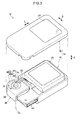
Fig. 1 is a perspective view illustrating a biometric data detection device of a first exemplary embodiment; -
Fig. 2 is a perspective view illustrating a biometric data detection device of the first exemplary embodiment; -
Fig. 3 is an exploded perspective view illustrating a biometric data detection device of the first exemplary embodiment; -
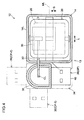
Fig. 4 is a horizontal cross-section illustrating a biometric data detection device of the first exemplary embodiment; -
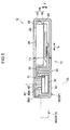
Fig. 5 is a vertical cross-section illustrating a biometric data detection device of the first exemplary embodiment; -
Fig. 6 is a plan view illustrating a state in which a biometric data detection device of the first exemplary embodiment is attached to a data processing terminal; -
Fig. 7 is a plan view illustrating a state in which a biometric data detection device of the first exemplary embodiment is attached to a data processing terminal; -
Fig. 8 is a plan view illustrating a state in which a biometric data detection device of the first exemplary embodiment is attached to a data processing terminal; -
Fig. 9 is a plan view illustrating a state in which a biometric data detection device of the first exemplary embodiment is attached to a data processing terminal; -
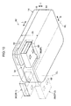
Fig. 10 is a perspective view illustrating a biometric data detection device of a second exemplary embodiment; -
Fig. 11 is a perspective view illustrating a biometric data detection device of a third exemplary embodiment; and -
Fig. 12 is a perspective view illustrating a biometric data detection device of a fourth exemplary embodiment - Detailed explanation follows regarding a first exemplary embodiment based on the drawings.
- A biometric
data detection device 12 of the first exemplary embodiment includes abiometric authentication unit 13. Thebiometric authentication unit 13 includes ahousing 14. In the example illustrated inFig. 1 to Fig. 3 , thehousing 14 is a substantially rectangular box shaped member. The length direction, the width direction, and the thickness direction of thehousing 14 are indicated in the drawings by the arrows L, S, and T respectively. These directions are directions given for convenience of explanation, and the directions the biometricdata detection device 12 is used in are not limited in practice. - The
housing 14 includes afront member 16 and arear member 18. A sensor placement space is formed inside thehousing 14 by contacting and joining thefront member 16 and therear member 18 together at their peripheries. As illustrated inFig. 4 andFig. 5 , the sensor placement space houses abiometric authentication sensor 20. - A
light transmitting window 22 is formed on thefront member 16. Thelight transmitting window 22 is covered by acover plate 24 that transmits light. Light transmitted through the light transmitting window 22 (the cover plate 24) is incident to anoptical receiver 26 of the biometric authentication sensor 20 (seeFig. 4 andFig. 5 ). - The face of the
front member 16 on which thelight transmitting window 22 is formed is awindowed face 28. Thebiometric authentication sensor 20 includes an extraction section. In a state in which there is a portion of a biological body against thewindowed face 28, the extraction section extracts biometric data from a biological body image of light received by theoptical receiver 26. Thebiometric authentication sensor 20 is electrically connected to a relay substrate 42, described later, through a connectingsubstrate 30 and a connectingcable 32. - Although the
light transmitting window 22 is illustrated with a planar shape (a substantially square shape, or a substantially rectangular shape) in the example illustrated inFig. 1 , thelight transmitting window 22 may, for example, be one or plural bar shapes (slit shapes). Employing a planar light transmitting window achieves a structure that enables, for example, thebiometric authentication sensor 20 to acquire biometric data by holding a palm or the like thereon. - In such cases, light detected by the
biometric authentication sensor 20 is not only visible light, but also may include, for example, infrared rays and ultraviolet rays. The biometricdata detection device 12 may be structured to include the source of such light. - Employing a bar shaped light transmitting window achieves a structure enabling, for example, the
biometric authentication sensor 20 to acquire biometric data by sliding a fingertip along the length direction of the light transmitting window. - A
housing recess portion 34 is formed at the rear side, and at one of the length direction sides of thehousing 14. Specifically, the length of therear member 18 is formed shorter than thefront member 16, thereby forming thehousing recess portion 34. - An
attachment member 36 is provided to thehousing recess portion 34. In the first exemplary embodiment, theattachment member 36 includes a rotatingbody 38, and a universal serial bus (USB)plug 40. The rotatingbody 38 is rotatable with respect to thehousing 14 about center line CL. TheUSB plug 40 protrudes out from the rotatingbody 38. TheUSB plug 40 is also referred to a male connector. - The rotating
body 38 is rotatably attached to thehousing 14 by arotation shaft 44. The rotatingbody 38 is a portion of theattachment member 36, and so theattachment member 36 is rotatably attached with respect to thehousing 14. Since thehousing 14 is rotatable about therotation shaft 44, thebiometric authentication unit 13 is also rotatable about therotation shaft 44. - The
rotation shaft 44 includes anattachment screw 46, aninner cylinder 48N, and anouter cylinder 48G. The attachment screw 46 screw-fastens the rotatingbody 38 to the housing 14 (the front member 16). Theinner cylinder 48N and theouter cylinder 48G are circular cylinder shaped members surrounding theattachment screw 46. Theouter cylinder 48G also houses the rotatingbody 38. A gap G is produced between theinner cylinder 48N and theouter cylinder 48G. The connectingcable 32 passes through the gap G. - The
biometric authentication sensor 20 and theUSB plug 40 are electrically connected through the connectingsubstrate 30 and the connectingcable 32. - As illustrated in
Fig. 5 , the rotation center line CL direction of the rotation shaft 44 (the attachment screw 46) is a direction normal to thewindowed face 28. Theattachment member 36 accordingly rotates about the center line CL with respect to thehousing 14 in a plane parallel to thewindowed face 28. - As illustrated in
Fig. 1 andFig. 4 , the center line CL is positioned on the side nearer to along edge 14L than a center line ML at the center in the width direction of the housing 14 (the upper side inFig. 1 andFig. 4 ), as viewed along a direction normal to thewindowed face 28. - The
attachment member 36 may adopt a stowed position SP indicated by solid lines inFig. 1 ,Fig. 2 ,Fig. 4 , andFig. 5 . In the stowed position SP, theentire attachment member 36 is positioned within the outline of thehousing 14, as viewed along a direction normal to thewindowed face 28. - The
attachment member 36 rotates about the center line CL. Theattachment member 36 rotates from the stowed position SP, through a first attachment position CP-1 indicated by a single dotted-dashed line, to a second attachment position CP-2 indicated by a doubled-dotted dashed line. In the present exemplary embodiment, the first attachment position CP-1 is positioned rotated 90degree from the stowed position SP. The second attachment position CP-2 is positioned rotated 180degree from the stowed position SP. - As illustrated in
Fig. 1 ,Fig. 2 , andFig. 5 , theattachment member 36 rotates within a range of a thickness T1 of thehousing 14. In other words, theattachment member 36 does not protrude out in the thickness direction of thehousing 14 when rotating from the stowed position SP to the second attachment position CP-2. - The
USB plug 40 protrudes to the outside thehousing 14 at the first attachment position CP-1 and the second attachment position CP-2 of theattachment member 36, as viewed along the direction normal to thewindowed face 28. As illustrated inFig. 6 , theUSB plug 40 protruding to the outside of thehousing 14 in this manner enables theUSB plug 40 to be inserted into aUSB connector 104 of atablet terminal 102 and thereby connected. The biometricdata detection device 12 is thereby attached to thetablet terminal 102, and thebiometric authentication sensor 20 is electrically connected to thetablet terminal 102 through theUSB plug 40. TheUSB connector 104 is an example of an insertion port into which theUSB plug 40 is inserted. Alower face 40B (or an upper face, seeFig. 2 ) of theUSB plug 40 is an example of a specific face. The center line CL (the rotation axis) is perpendicular to the specific face. Thelower face 40B (or the upper face) of theUSB plug 40 is parallel to the cover plate 24 (the face of the window portion) and thewindowed face 28. - The
tablet terminal 102 is an example of a member to which the biometricdata detection device 12 connects, namely, an example of a data processing terminal. Thetablet terminal 102 may display data on adisplay 106. Thedisplay 106 is an example of a display section. TheUSB plug 40 is an example of a connecting member that connects thebiometric authentication sensor 20 to thetablet terminal 102. Various members (plugs) compatible with connectors of tablet terminals may be employed as the connecting member. - In the present exemplary embodiment the
attachment member 36 rotates with respect to thehousing 14 about the center line CL. As indicated by the solid line and the double-dotted dashed line inFig. 6 , thehousing 14 can thereby be rotated in a state in which theUSB plug 40 has been inserted into theUSB connector 104. The first attachment position CP-1 and the second attachment position CP-2 of theattachment member 36 are both therefore examples of attachment positions with respect to thetablet terminal 102. Positions between the first attachment position CP-1 and the second attachment position CP-2 are also attachment positions at which theUSB plug 40 may be inserted into theUSB connector 104 and thereby connected. - In an attached state to the
tablet terminal 102, thehousing 14 of the biometricdata detection device 12 thus rotates with respect to thetablet terminal 102 between an orientation (a first orientation SS-1) indicated by the solid line, and an orientation (a second orientation SS-2) indicated by the double-dotted dashed line inFig. 6 . The orientation of the windowed face 28 (the light transmitting window 22) is also rotated by this rotation. In the second orientation SS-2, awindow edge 22A of thelight transmitting window 22 faces thetablet terminal 102 side. - In the present exemplary embodiment the
biometric authentication sensor 20 and thetablet terminal 102 are electrically connected together, and thehousing 14 is attached to thetablet terminal 102, by theUSB plug 40. Namely, a structure in which theUSB plug 40 is rotatably attached to thehousing 14 serves as theattachment member 36. As illustrated inFig. 6 , for example, in the second orientation SS-2, by rotating the housing 14 (the biometric authentication unit 13) it is possible to position thewindow edge 22A at the side for acquiring biometric data of thefingertip 202A side of apalm 202 during authentication of thepalm 202. The rotation direction of thehousing 14 may also be set to a rotated direction in which thewindow edge 22A is not positioned at the side for acquiring biometric data from thefingertip 202A side of thepalm 202. - The biometric
data detection device 12 can be easily removed from thetablet terminal 102 by pulling out theUSB plug 40 from the USB connector 104 (the electrical connection is also eliminated). - As illustrated in
Fig. 1 , one out of fourcorner portions 50 as viewed along a direction normal to thehousing 14 is anon-contact portion 50C. Thenon-contact portion 50C is a shorter distance from the center line CL (has a shorter radius of curvature R2) than edges at either side of thenon-contact portion 50C. The radius of curvature R2 of thenon-contact portion 50C is longer than a radius of curvature R1 of the other three corner portions. As illustrated inFig. 6 , the position and shape of thenon-contact portion 50C is a position that approaches thetablet terminal 102 when the biometricdata detection device 12 is rotated between the first orientation SS-1 and the second orientation SS-2. However, due to thenon-contact portion 50C being formed, thehousing 14 does not make contact with thetablet terminal 102 during rotation, even when rotating between the first orientation SS-1 and the second orientation SS-2. - The specific shape of the
non-contact portion 50C in the present exemplary embodiment is, for example, an arc shape (with a central angle of 90degree) at a constant distance from the center line CL (radius of curvature R2) as illustrated inFig. 1 . - As illustrated in
Fig. 1 andFig. 2 , astrap hole 52 is formed in thehousing 14. Attaching a strap to thestrap hole 52 enables the biometricdata detection device 12 to be easily carried by gripping the strap or the like. The user prevents the biometricdata detection device 12 from being dropped by keeping hold of the strap. - Explanation next follow regarding operation of the present exemplary embodiment.
- As illustrated in
Fig. 6 , the biometricdata detection device 12 and thetablet terminal 102 are electrically connected by inserting theUSB plug 40 of the biometricdata detection device 12 into theUSB connector 104 of thetablet terminal 102. Since theUSB plug 40 is provided to theattachment member 36, inserting theUSB plug 40 into theUSB connector 104 attaches the biometricdata detection device 12 to thetablet terminal 102. - In a state in which the biometric
data detection device 12 is thus attached (connected) to thetablet terminal 102, light is received from the biological body by theoptical receiver 26 of thebiometric authentication sensor 20 when a portion of the biological body, such as a palm or a finger, is placed over thelight transmitting window 22. Thebiometric authentication sensor 20 then extracts biometric data from the biological body image. The extracted biometric data is sent to thetablet terminal 102 through theUSB plug 40, enabling thetablet terminal 102 to authenticate and identify the user. For example, whenplural tablet terminals 102 are shared by plural people, the secured (locked) state of thetablet terminal 102 can be deactivated by identifying the user via the biometricdata detection device 12, and transition then made to setting states for individual users. - The
tablet terminal 102 can be held in various ways, and usage in plural directions is conceivable. Specifically, for example, usage in a first direction that positions ashort edge 102S vertically (the direction illustrated inFig. 6 ), and usage in a second direction that positions along edge 102L vertically (the direction illustrated inFig. 7 ) are conceivable. The first direction and the second direction are mutually perpendicular. As illustrated inFig. 6 andFig. 7 , the direction for displaying on thedisplay 106 may also be switched between a first direction (the direction illustrated inFig. 6 ) and a second direction (the direction illustrated inFig. 7 ). - In a state in which the biometric
data detection device 12 is attached to thetablet terminal 102, the orientation of thelight transmitting window 22 of the biometricdata detection device 12 is rotated simply by rotating thetablet terminal 102 in an arrow R3 direction. - In some cases, the orientation of the biological body with respect to the
light transmitting window 22 is renewed so that stable authentication of the biological body can be achieved. In such cases, were thetablet terminal 102 and the biometricdata detection device 12 to both be rotated, then the portion (palm, finger, or the like) placed over thelight transmitting window 22 would also have to be rotated while authenticating thetablet terminal 102. - In contrast thereto, the
attachment member 36 of the biometricdata detection device 12 of the present exemplary embodiment rotates with respect to thehousing 14 about the center line CL. This thereby enables the biometricdata detection device 12 to maintain an attached state to thetablet terminal 102 while being rotated. Specifically, the first orientation SS-1 may be adopted in which the length direction of thehousing 14 matches the length direction of thetablet terminal 102, as indicated by the solid line inFig. 6 . When thepalm 202, an example of a biological body, is then placed over thelight transmitting window 22, thefingertip 202A (the distal end of the biological body) side of the biological body, as indicated by the arrow M1 inFig. 6 , is positioned at thelight transmitting window 22 side (the window portion side) of thebiometric authentication unit 13. Accordingly, thepalm 202 on the opposite side of the biological body to the side of thefingertip 202A (the non-distal end of the biological body) does not cover thedisplay 106. Sometimes thedisplay 106 displays, for example, authentication guidance, authentication results, or the like, however since thedisplay 106 is not covered by a portion of the biological body, it is possible to suppress this data from becoming difficult to see. - As illustrated in
Fig. 7 , the biometricdata detection device 12 can be rotated from the first orientation SS-1 to the second orientation SS-2 while maintaining the attached state to thetablet terminal 102. In the second orientation SS-2, the length direction of thehousing 14 matches the width direction of thetablet terminal 102. The orientation of thewindowed face 28 can be thus modified to an orientation appropriate to biometric data acquisition. In this state also, when thepalm 202, an example of the biological body, is placed over thelight transmitting window 22, thefingertip 202A side (the distal end of the biological body) of the biological body is positioned at thelight transmitting window 22 side (the window portion side) of thebiometric authentication unit 13. Thepalm 202, on the side opposite of the biological body to the side of thefingertip 202A (the non-distal end of the biological body), does not cover thedisplay 106. Sometimes thedisplay 106 displays, for example, authentication guidance, authentication results, or the like, and since thedisplay 106 is not covered by a portion of the biological body, it is possible to suppress this data from becoming difficult to see. - In other words, for the site of the biological body (the palm 202) to be scanned by the
biometric authentication sensor 20, the direction B1 from thefingertip 202A (distal end) toward the non-distal end is variable to either the first direction or the second direction described above by rotating thebiometric authentication unit 13. - This thereby enables the orientation of the biometric
data detection device 12 with respect to the user (biological body) to be maintained even when the orientation of thetablet terminal 102 is rotated with respect to the user. There is no need, therefore, to change the direction of the portion of the biological body (palm, finger, or the like) or to switch grip on thetablet terminal 102 when placing a portion of a biological body over thelight transmitting window 22. - In particular, as illustrated in
Fig. 1 , in the present exemplary embodiment, one out of the fourcorner portions 50 as viewed along a direction normal to thehousing 14 is thenon-contact portion 50C. Thus when rotating the biometricdata detection device 12, the biometricdata detection device 12 can be rotated smoothly without contact or interference that would hinder rotation between thehousing 14 and thetablet terminal 102. - The connected state between the biometric
data detection device 12 and thetablet terminal 102 is maintained even in a freely selected position between the first attachment position CP-1 and the second attachment position CP-2. For example, the connected state is maintained even when the biometricdata detection device 12 is angled with respect to thetablet terminal 102, between the first orientation SS-1 and the second orientation SS-2. - In the first exemplary embodiment, the
USB plug 40 is a member that electrically connects thebiometric authentication sensor 20 of the biometricdata detection device 12 to thetablet terminal 102, namely, an example of a connecting member. TheUSB plug 40 is provided to therotating body 38 of theattachment member 36, and the connecting member is rotatably provided to the housing as theattachment member 36. The USB plug 40 (the connecting member) therefore has less parts than in a structure in which theUSB plug 40 is a separate body to theattachment member 36. - In a structure in which the
USB plug 40 is a separate body from theattachment member 36, it is conceivable that a cable that connects theUSB plug 40 and thebiometric authentication sensor 20 would be exposed outside thehousing 14. In the first exemplary embodiment, the exposed portion of the connectingcable 32 that connects to the outside of thehousing 14 can be made smaller, making handling easier and giving excellent durability of the cable. - The first exemplary embodiment includes the
rotation shaft 44. Thus in contrast to structures having no rotation shaft 44 (for example, a structure that guides rotation using an arc shaped groove and a ridge), more stable rotation maintaining the center line CL for rotation can be realized since theattachment member 36 is rotatably attached to thehousing 14 by therotation shaft 44. - In particular, as illustrated in
Fig. 3 andFig. 5 , the first exemplary embodiment has a structure in which the connectingcable 32 passes through the interior of therotation shaft 44. Accordingly, in contrast to structures in which the connectingcable 32 passes outside of therotation shaft 44, the exposed portion of the connectingcable 32 that connects to the outside of thehousing 14 can be made smaller, making handling easier and giving excellent durability of the cable. - In the first exemplary embodiment, the
housing 14 rotatably supports therotation shaft 44 at one axial direction side thereof through theattachment screw 46. This thereby enables the structure to be simplified compared to a structure in which arotation shaft 44 is supported at both axial direction sides. - As illustrated in
Fig. 8 andFig. 9 , theUSB connector 104 may be provided to along edge 102L of thetablet terminal 102. In the example illustrated inFig. 8 , the usage state is one in which the arrow A direction is the vertical direction and theUSB connector 104 is positioned at the upper side. In the example illustrated inFig. 9 , the usage state in one in which the arrow B direction is the vertical direction and theUSB connector 104 is positioned at a lateral side. - As illustrated in
Fig. 6 , in the first exemplary embodiment, a portion of an edge of thetablet terminal 102 is sometimes covered by thehousing 14 when the biometricdata detection device 12 is attached to thetablet terminal 102. The portion covered by thehousing 14 sometimes includes a functional component of the tablet terminal 102 (such as a connection terminal or a type of switch). The functional component can be exposed to achieve a usable state by appropriately rotating the biometricdata detection device 12. - Explanation next follows regarding a second exemplary embodiment. In the second exemplary embodiment, elements, members, and the like that are similar to those of the first exemplary embodiment are appended with the same reference numerals in the drawings as the first exemplary embodiment, and detailed explanation thereof is omitted.
- A rear member 64 in a biometric
data detection device 62 of the second exemplary embodiment includes a projectingsection 66. The projectingsection 66 projects out toward the rear side of arotating body 38 of anattachment member 36. The projectingsection 66 covers the rotatingbody 38 from the rear side. Arotation shaft 44 is supported at both sides by two members, these being afront member 16 and the projectingsection 66. - In the biometric
data detection device 62 of the second exemplary embodiment, the rotation shaft 44 (seeFig. 3 andFig. 5 ) is thereby supported at both sides. In other words, theattachment member 36 is supported by being gripped from both thickness direction sides. Attachment strength and rotation strength of theattachment member 36 with respect to thehousing 14 is thereby enhanced. - Explanation next follows regarding a third exemplary embodiment. In the third exemplary embodiment, elements, members, and the like similar to those of the first exemplary embodiment are appended with the same reference numerals in the drawings as the first exemplary embodiment, and detailed explanation thereof is omitted.
- As illustrated in
Fig. 11 , in a biometricdata detection device 72 of the third exemplary embodiment, anattachment member 74 and a connectingmember 76 are separate bodies. The connectingmember 76 includes aUSB plug 40 and a connectingcable 32. The connectingcable 32 electrically connects a biometric authentication sensor 20 (seeFig. 4 andFig. 5 ) and theUSB plug 40. - The
attachment member 74 includes aclip 78. Theclip 78 includes twoplate members plate member 78A has a flat plate shape, and is attached to ahousing 14 so as to be rotatable about a center line CL. Theclip 78 rotates from a stowed position SP indicated by the solid line, through a first attachment position CP-1 indicated by the single-dotted dashed line, to a second attachment position CP-2 indicated by the double-dotted dashed line inFig. 11 . - The
other plate member 78B bends obtusely near the length direction center, and is attached to the oneplate member 78A at the bent portion so as to be capable of swinging in the arrow Y1 direction with respect to the oneplate member 78A. - The
clip 78 includes a spring. The spring biases theplate member 78B toward theplate member 78A so as to close atip 78T side of the clip 78 (such that theplate member 78B contacts theplate member 78A). Theplate member 78B can be separated from theplate member 78A at thetip 78T side by countering the biasing force of the spring. - In the third exemplary embodiment, the biometric
data detection device 72 can be clamped and attached to a tablet terminal 102 (seeFig. 6 ) using the attachment member 74 (the clip 78). Thebiometric authentication sensor 20 of the biometric data detection device 72 (seeFig. 4 andFig. 5 ) can be electrically connected to thetablet terminal 102 by theUSB plug 40. - The orientation of a windowed face 28 (see
Fig. 1 ) can then be modified by rotating the biometricdata detection device 12 while the biometricdata detection device 72 is retained in an attached state to thetablet terminal 102. - In the first exemplary embodiment to the third exemplary embodiment, when the attachment member is in the stowed position SP, the whole of the attachment member is positioned inside the
housing 14, as viewed along a direction normal to thewindowed face 28. The attachment member has excellent storability and portability since the attachment member does not jut out to the outside of the housing in the stowed position SP. - In the first exemplary embodiment to the third exemplary embodiment, the attachment member rotates from the stowed position SP to arrive at the first attachment position CP-1. When in the stowed position SP, the
USB plug 40 is positioned inside thehousing 14, as viewed along a direction normal to thewindowed face 28. TheUSB plug 40 can thereby be positioned so as to be connectable to thetablet terminal 102 by the simple action of rotating the attachment member from the stowed position SP. - Explanation next follows regarding a fourth exemplary embodiment. In the fourth exemplary embodiment, elements, members, and the like similar to those of the first exemplary embodiment are appended with the same reference numerals in the drawings as the first exemplary embodiment, and detailed explanation thereof is omitted.
- As illustrated in
Fig. 12 , in a biometric data detection device 82 of the fourth exemplary embodiment, anattachment member 84 and a connectingmember 86 are separate bodies. The connectingmember 86 includes aUSB plug 40 and a connectingcable 32. The connectingcable 32 electrically connects a biometric authentication sensor 20 (seeFig. 4 andFig. 5 ) and theUSB plug 40. - The
attachment member 84 includes arotating body 88. The rotatingbody 88 is attached to ahousing 14 so as to be rotatable about a center line CL. Abottom face 88R of therotating body 88 is in the same position in the thickness direction as arear face 14R of thehousing 14, or positioned further to the rear side (the arrow R direction side) than therear face 14R. - A hook-and-
loop fastener 90 is attached to thebottom face 88R of therotating body 88. In the fourth exemplary embodiment, a hook-and-loop fastener is also attached to a tablet terminal 102 (seeFig. 6 ). - In the fourth exemplary embodiment, the biometric data detection device 82 can be attached to the tablet terminal 102 (see
Fig. 6 ) using theattachment member 84. Thebiometric authentication sensor 20 of the biometric data detection device 82 (seeFig. 4 andFig. 5 ) and thetablet terminal 102 can be electrically connected by theUSB plug 40. - The orientation of a
windowed face 28 can then be modified by rotating the biometric data detection device 82 while the biometric data detection device 82 is retained in an attached state to thetablet terminal 102 by the connectingmember 86. - In each of the exemplary embodiments described above, in the
housing 14 the center line CL is offset further to onelong edge 102L side than the center line ML (seeFig. 5 ). As illustrated inFig. 6 , in an attached state to theshort edge 102S of thetablet terminal 102, the biometric data detection device is oriented along theshort edge 102S, as indicated by the double-dotted dashed line, enabling the biometric data detection device to be positioned near to thetablet terminal 102. - Consider a structure in which the
USB connector 104 of thetablet terminal 102 is provided to thelong edge 102L. In an attached state to thelong edge 102L at the lower side of thetablet terminal 102, the biometric data detection device can be orientated along thelong edge 102L, namely, the biometric data detection device can be positioned close to thetablet terminal 102. - The biometric data detection device can thereby be positioned close to the
tablet terminal 102, both when attached to thelong edge 102S, and when attached to thelong edge 102L of thetablet terminal 102. Namely, an overall reduction in size is enabled in a state in which the biometric data detection device is attached to thetablet terminal 102. - In each of the exemplary embodiments described above, the attachment member rotates with respect to the
housing 14 in a plane parallel to thewindowed face 28. In a state in which the biometric data detection device is attached to thetablet terminal 102, the orientation of thewindowed face 28 can accordingly be modified by movement (rotation) in a single plane parallel to thewindowed face 28. - The attachment member rotates with respect to the
housing 14 within the range of the thickness T1 of thehousing 14. The biometric data detection device has excellent storability and portability since the attachment member does not jut out in the thickness direction from thehousing 14, even when the attachment member is rotated. - The data processing terminal that connects to the biometric data detection device is not limited to the
tablet terminal 102 described above, and may be a cellphone, a smartphone, or the like. Moreover, the data processing terminal may be a terminal for managing goods in factories, warehouses, shops, and the like. - Although explanation regarding exemplary embodiments of technology disclosed herein has been given above, technology disclosed herein is not limited thereto, and obviously various modifications other than those described above may be implemented within a range not departing from the spirit of the present invention.
- Technology disclosed herein enables the orientation of a windowed face that acquires biometric data to be modified, while maintaining a state of attachment to a data processing terminal.
- All publications, patent applications and technical standards mentioned in the present specification are incorporated by reference in the present specification to the same extent as if the individual publication, patent application, or technical standard was specifically and individually indicated to be incorporated by reference.
Claims (15)
- A biometric data detection device (12,62,72,82) comprising:a biometric authentication sensor (20) electrically connected to a data processing terminal through a connecting member;a housing (14) that houses the biometric authentication sensor;a window portion (22) that acquires biometric data to be authenticated by the biometric authentication sensor, and that is formed in the housing; andan attachment member (36) that is rotatably provided at the housing, and that renders the housing rotatable in a state in which the housing is attached to the data processing terminal.
- The biometric data detection device of claim 1, wherein, as the attachment member, the connecting member (40) is rotatably attached to the housing.
- The biometric data detection device of claim 1 or claim 2, wherein:the housing includes a windowed face on which the window portion is formed; andthe attachment member rotates along a plane parallel to the windowed face.
- The biometric data detection device of claim 3, wherein the attachment member rotates with respect to the housing within a range of a housing thickness that runs along a direction normal to the windowed face.
- The biometric data detection device of any one of claim 1 to claim 4, further comprising a rotation shaft (44) that retains the attachment member so as to be rotatable with respect to the housing.
- The biometric data detection device of claim 5, wherein a connection cable (32) connecting the connecting member and the biometric authentication sensor together passes through an interior of the rotation shaft.
- The biometric data detection device of claim 5 or claim 6, wherein the housing supports the rotation shaft at one axial direction side.
- The biometric data detection device of claim 5 or claim 6, wherein the housing supports the rotation shaft at both axial direction sides.
- The biometric data detection device of any one of claim 1 to claim 8, wherein, by rotation, the entire attachment member adopts a stowed position in which the attachment member is positioned inside the housing, as viewed along a direction normal to a windowed face on which the window portion is formed.
- The biometric data detection device of claim 9, wherein the attachment member arrives at an attachment position protruding from the housing, as viewed along the normal direction, by rotation of the attachment member from the stowed position.
- The biometric data detection device of any one of claim 1 to claim 10, wherein a center of rotation of the attachment member with respect to the housing is offset toward one long edge side of the housing, as viewed along a direction normal to a windowed face on which the window portion is formed.
- The biometric data detection device of any one of claim 1 to claim 11, wherein, the housing is formed with a non-contact portion that permits rotation of the housing with respect to the data processing terminal, without contacting the data processing terminal, in the state in which the housing is attached to the data processing terminal.
- The biometric data detection device of claim 1, wherein:the connecting member is inserted into an insertion port of the data processing terminal; anddue to the housing being rotatable about a rotation axis perpendicular to a specific face of the connecting member, a windowed face on which the window portion is formed is positioned parallel to the specific face.
- The biometric data detection device of claim 13, wherein, by the rotation, a side of the window portion facing the data processing terminal is positioned at a side of the biometric authentication unit that acquires biometric data at a distal end side of a biological body.
- The biometric data detection device of claim 13, wherein, in a state of being connected to the data processing terminal, the direction of the rotation is set such that a side of the window portion facing toward the side of the data processing terminal is not positioned at a side of the biometric authentication unit for acquiring biometric data from a non-distal end side of a biological body.
Applications Claiming Priority (1)
| Application Number | Priority Date | Filing Date | Title |
|---|---|---|---|
| JP2014100039A JP6405694B2 (en) | 2014-05-13 | 2014-05-13 | Biological information detection device |
Publications (2)
| Publication Number | Publication Date |
|---|---|
| EP2945103A1 true EP2945103A1 (en) | 2015-11-18 |
| EP2945103B1 EP2945103B1 (en) | 2018-03-07 |
Family
ID=52875055
Family Applications (1)
| Application Number | Title | Priority Date | Filing Date |
|---|---|---|---|
| EP15163838.4A Not-in-force EP2945103B1 (en) | 2014-05-13 | 2015-04-16 | Biometric data detection device |
Country Status (4)
| Country | Link |
|---|---|
| US (1) | US10007774B2 (en) |
| EP (1) | EP2945103B1 (en) |
| JP (1) | JP6405694B2 (en) |
| CN (1) | CN105095712A (en) |
Families Citing this family (7)
| Publication number | Priority date | Publication date | Assignee | Title |
|---|---|---|---|---|
| US10848321B2 (en) | 2017-11-03 | 2020-11-24 | Mastercard International Incorporated | Systems and methods for authenticating a user based on biometric and device data |
| CN109064588A (en) * | 2018-07-11 | 2018-12-21 | 泉州信息工程学院 | A kind of wireless software coded lock |
| CN109409485B (en) * | 2018-10-25 | 2021-09-10 | 安徽省临泉县康悦电子科技有限公司 | Waterproof encrypted USB flash disk |
| WO2020187299A2 (en) * | 2019-03-19 | 2020-09-24 | 浙江大学山东工业技术研究院 | Smartphone-based testing apparatus |
| US11620366B2 (en) * | 2019-12-04 | 2023-04-04 | Motorola Mobility Llc | Device enabling user preferred functions, preferences, and settings in another electronic device and corresponding methods |
| USD989772S1 (en) * | 2021-05-04 | 2023-06-20 | Rf Ideas, Inc. | Dongle |
| US12332991B2 (en) | 2022-07-26 | 2025-06-17 | Rsa Security Usa, Llc | Hardware authentication device |
Citations (3)
| Publication number | Priority date | Publication date | Assignee | Title |
|---|---|---|---|---|
| JP2000148963A (en) * | 1998-11-05 | 2000-05-30 | Fujitsu Takamisawa Component Ltd | Fingerprint collation pc card |
| WO2004066132A1 (en) * | 2003-01-21 | 2004-08-05 | Mitsui & Co., Ltd. | External electronic device |
| US20060219776A1 (en) * | 2003-11-17 | 2006-10-05 | Dpd Patent Trust | Rfid reader with multiple interfaces |
Family Cites Families (16)
| Publication number | Priority date | Publication date | Assignee | Title |
|---|---|---|---|---|
| US6234389B1 (en) * | 1998-04-29 | 2001-05-22 | @Pos.Com, Inc. | PCMCIA-based point of sale transaction system |
| JP2000048177A (en) | 1998-07-30 | 2000-02-18 | Fujitsu Takamisawa Component Ltd | Card with fingerprint scanner |
| US6357663B1 (en) | 1998-07-30 | 2002-03-19 | Fujitsu Takamisawa Component Limited | Fingerprint identifying PC card |
| JP2000293688A (en) * | 1999-04-01 | 2000-10-20 | Fujitsu Ltd | Fingerprint collation device |
| US6490163B1 (en) * | 2001-08-30 | 2002-12-03 | Phison Electronic Corp. | Computer readable portable data storage device |
| TW551552U (en) * | 2002-04-19 | 2003-09-01 | Carry Computer Eng Co Ltd | Dual-interface CF card |
| US7025275B2 (en) | 2004-01-27 | 2006-04-11 | Micro-Star Int'l Co. Ltd. | External connecting electronic apparatus |
| JP2006107366A (en) | 2004-10-08 | 2006-04-20 | Fujitsu Ltd | Biometric information input device, biometric authentication device, biometric information processing method, biometric information processing program, and computer-readable recording medium recording the program |
| US7009847B1 (en) * | 2004-12-20 | 2006-03-07 | Inventec Multimedia & Telecom Corporation | Connector concealment mechanism for computer peripheral device |
| USD559249S1 (en) * | 2006-07-21 | 2008-01-08 | Sony Corporation | Portable hard disk drive |
| CN201004323Y (en) | 2007-01-12 | 2008-01-09 | 裴如锋 | Card U disk |
| JP5101908B2 (en) | 2007-03-16 | 2012-12-19 | 富士通株式会社 | Electronics |
| JP2009192860A (en) * | 2008-02-15 | 2009-08-27 | Konica Minolta Business Technologies Inc | Image forming apparatus |
| US8766928B2 (en) * | 2009-09-25 | 2014-07-01 | Apple Inc. | Device, method, and graphical user interface for manipulating user interface objects |
| CN201550379U (en) | 2009-11-05 | 2010-08-11 | 华为终端有限公司 | Rotary shaft, digital equipment and universal series bus USB equipment |
| US8127996B1 (en) * | 2010-02-16 | 2012-03-06 | MedID Technologies, Inc. | Customizable portable identification and memory device |
-
2014
- 2014-05-13 JP JP2014100039A patent/JP6405694B2/en not_active Expired - Fee Related
-
2015
- 2015-04-14 US US14/685,961 patent/US10007774B2/en active Active
- 2015-04-16 EP EP15163838.4A patent/EP2945103B1/en not_active Not-in-force
- 2015-04-29 CN CN201510212417.9A patent/CN105095712A/en active Pending
Patent Citations (3)
| Publication number | Priority date | Publication date | Assignee | Title |
|---|---|---|---|---|
| JP2000148963A (en) * | 1998-11-05 | 2000-05-30 | Fujitsu Takamisawa Component Ltd | Fingerprint collation pc card |
| WO2004066132A1 (en) * | 2003-01-21 | 2004-08-05 | Mitsui & Co., Ltd. | External electronic device |
| US20060219776A1 (en) * | 2003-11-17 | 2006-10-05 | Dpd Patent Trust | Rfid reader with multiple interfaces |
Also Published As
| Publication number | Publication date |
|---|---|
| JP6405694B2 (en) | 2018-10-17 |
| CN105095712A (en) | 2015-11-25 |
| US10007774B2 (en) | 2018-06-26 |
| US20150332035A1 (en) | 2015-11-19 |
| EP2945103B1 (en) | 2018-03-07 |
| JP2015219537A (en) | 2015-12-07 |
Similar Documents
| Publication | Publication Date | Title |
|---|---|---|
| EP2945103A1 (en) | Biometric data detection device | |
| US9066125B2 (en) | Secure display | |
| US9529387B2 (en) | Docking sleeve with electrical adapter | |
| US9632535B2 (en) | Docking sleeve with electrical adapter | |
| JP7070588B2 (en) | Biometrics, systems, methods and programs | |
| US20170032166A1 (en) | Handheld biometric scanner device | |
| EP2172911A2 (en) | Authentication apparatus | |
| US20210405779A1 (en) | Electronic stylus having image capabilities | |
| JP2017516208A5 (en) | ||
| EP3734410A1 (en) | Docking sleeve with electrical adapter | |
| EP2811738A2 (en) | Mobile phone or portable PC with a camera | |
| KR20180021688A (en) | Docking sleeve with electrical adapter | |
| US20180219992A1 (en) | Hand held biometric mount for mobile phones | |
| RU2737423C2 (en) | Improved portable system for three-dimensional scanning using smartphone | |
| US10185358B1 (en) | Electronic tablet protective carrying case and display stand | |
| EP3596473B1 (en) | Accessory for a mobile device to measure characteristics of a test strip | |
| US10567023B2 (en) | Indicator detecting device | |
| CN105723762B (en) | Authentication system for mobile data terminal equipment | |
| CN104898212A (en) | Communication light detection adapter and communication light detection structure | |
| US10224726B1 (en) | Electrical connection assembly for base unit of battery-powered handheld ID code reader | |
| CN108369441A (en) | Attachment between tablet device and keyboard | |
| JP7216312B1 (en) | Authenticator and program | |
| EP3680804A1 (en) | System and method for reading information code | |
| US20250238492A1 (en) | Identity indication apparatus | |
| CN215495031U (en) | Scanning device for checking characters on surface of medicine bottle |
Legal Events
| Date | Code | Title | Description |
|---|---|---|---|
| PUAI | Public reference made under article 153(3) epc to a published international application that has entered the european phase |
Free format text: ORIGINAL CODE: 0009012 |
|
| AK | Designated contracting states |
Kind code of ref document: A1 Designated state(s): AL AT BE BG CH CY CZ DE DK EE ES FI FR GB GR HR HU IE IS IT LI LT LU LV MC MK MT NL NO PL PT RO RS SE SI SK SM TR |
|
| AX | Request for extension of the european patent |
Extension state: BA ME |
|
| 17P | Request for examination filed |
Effective date: 20160510 |
|
| RBV | Designated contracting states (corrected) |
Designated state(s): AL AT BE BG CH CY CZ DE DK EE ES FI FR GB GR HR HU IE IS IT LI LT LU LV MC MK MT NL NO PL PT RO RS SE SI SK SM TR |
|
| 17Q | First examination report despatched |
Effective date: 20170411 |
|
| GRAP | Despatch of communication of intention to grant a patent |
Free format text: ORIGINAL CODE: EPIDOSNIGR1 |
|
| INTG | Intention to grant announced |
Effective date: 20171109 |
|
| GRAS | Grant fee paid |
Free format text: ORIGINAL CODE: EPIDOSNIGR3 |
|
| GRAA | (expected) grant |
Free format text: ORIGINAL CODE: 0009210 |
|
| AK | Designated contracting states |
Kind code of ref document: B1 Designated state(s): AL AT BE BG CH CY CZ DE DK EE ES FI FR GB GR HR HU IE IS IT LI LT LU LV MC MK MT NL NO PL PT RO RS SE SI SK SM TR |
|
| REG | Reference to a national code |
Ref country code: GB Ref legal event code: FG4D |
|
| REG | Reference to a national code |
Ref country code: CH Ref legal event code: EP Ref country code: AT Ref legal event code: REF Ref document number: 977324 Country of ref document: AT Kind code of ref document: T Effective date: 20180315 |
|
| REG | Reference to a national code |
Ref country code: IE Ref legal event code: FG4D |
|
| REG | Reference to a national code |
Ref country code: DE Ref legal event code: R096 Ref document number: 602015008518 Country of ref document: DE |
|
| REG | Reference to a national code |
Ref country code: NL Ref legal event code: MP Effective date: 20180307 |
|
| REG | Reference to a national code |
Ref country code: LT Ref legal event code: MG4D |
|
| PG25 | Lapsed in a contracting state [announced via postgrant information from national office to epo] |
Ref country code: NO Free format text: LAPSE BECAUSE OF FAILURE TO SUBMIT A TRANSLATION OF THE DESCRIPTION OR TO PAY THE FEE WITHIN THE PRESCRIBED TIME-LIMIT Effective date: 20180607 Ref country code: FI Free format text: LAPSE BECAUSE OF FAILURE TO SUBMIT A TRANSLATION OF THE DESCRIPTION OR TO PAY THE FEE WITHIN THE PRESCRIBED TIME-LIMIT Effective date: 20180307 Ref country code: CY Free format text: LAPSE BECAUSE OF FAILURE TO SUBMIT A TRANSLATION OF THE DESCRIPTION OR TO PAY THE FEE WITHIN THE PRESCRIBED TIME-LIMIT Effective date: 20180307 Ref country code: HR Free format text: LAPSE BECAUSE OF FAILURE TO SUBMIT A TRANSLATION OF THE DESCRIPTION OR TO PAY THE FEE WITHIN THE PRESCRIBED TIME-LIMIT Effective date: 20180307 Ref country code: LT Free format text: LAPSE BECAUSE OF FAILURE TO SUBMIT A TRANSLATION OF THE DESCRIPTION OR TO PAY THE FEE WITHIN THE PRESCRIBED TIME-LIMIT Effective date: 20180307 Ref country code: ES Free format text: LAPSE BECAUSE OF FAILURE TO SUBMIT A TRANSLATION OF THE DESCRIPTION OR TO PAY THE FEE WITHIN THE PRESCRIBED TIME-LIMIT Effective date: 20180307 |
|
| REG | Reference to a national code |
Ref country code: AT Ref legal event code: MK05 Ref document number: 977324 Country of ref document: AT Kind code of ref document: T Effective date: 20180307 |
|
| PG25 | Lapsed in a contracting state [announced via postgrant information from national office to epo] |
Ref country code: GR Free format text: LAPSE BECAUSE OF FAILURE TO SUBMIT A TRANSLATION OF THE DESCRIPTION OR TO PAY THE FEE WITHIN THE PRESCRIBED TIME-LIMIT Effective date: 20180608 Ref country code: LV Free format text: LAPSE BECAUSE OF FAILURE TO SUBMIT A TRANSLATION OF THE DESCRIPTION OR TO PAY THE FEE WITHIN THE PRESCRIBED TIME-LIMIT Effective date: 20180307 Ref country code: SE Free format text: LAPSE BECAUSE OF FAILURE TO SUBMIT A TRANSLATION OF THE DESCRIPTION OR TO PAY THE FEE WITHIN THE PRESCRIBED TIME-LIMIT Effective date: 20180307 Ref country code: BG Free format text: LAPSE BECAUSE OF FAILURE TO SUBMIT A TRANSLATION OF THE DESCRIPTION OR TO PAY THE FEE WITHIN THE PRESCRIBED TIME-LIMIT Effective date: 20180607 Ref country code: RS Free format text: LAPSE BECAUSE OF FAILURE TO SUBMIT A TRANSLATION OF THE DESCRIPTION OR TO PAY THE FEE WITHIN THE PRESCRIBED TIME-LIMIT Effective date: 20180307 |
|
| PG25 | Lapsed in a contracting state [announced via postgrant information from national office to epo] |
Ref country code: NL Free format text: LAPSE BECAUSE OF FAILURE TO SUBMIT A TRANSLATION OF THE DESCRIPTION OR TO PAY THE FEE WITHIN THE PRESCRIBED TIME-LIMIT Effective date: 20180307 Ref country code: AL Free format text: LAPSE BECAUSE OF FAILURE TO SUBMIT A TRANSLATION OF THE DESCRIPTION OR TO PAY THE FEE WITHIN THE PRESCRIBED TIME-LIMIT Effective date: 20180307 Ref country code: PL Free format text: LAPSE BECAUSE OF FAILURE TO SUBMIT A TRANSLATION OF THE DESCRIPTION OR TO PAY THE FEE WITHIN THE PRESCRIBED TIME-LIMIT Effective date: 20180307 Ref country code: IT Free format text: LAPSE BECAUSE OF FAILURE TO SUBMIT A TRANSLATION OF THE DESCRIPTION OR TO PAY THE FEE WITHIN THE PRESCRIBED TIME-LIMIT Effective date: 20180307 Ref country code: RO Free format text: LAPSE BECAUSE OF FAILURE TO SUBMIT A TRANSLATION OF THE DESCRIPTION OR TO PAY THE FEE WITHIN THE PRESCRIBED TIME-LIMIT Effective date: 20180307 Ref country code: EE Free format text: LAPSE BECAUSE OF FAILURE TO SUBMIT A TRANSLATION OF THE DESCRIPTION OR TO PAY THE FEE WITHIN THE PRESCRIBED TIME-LIMIT Effective date: 20180307 |
|
| PG25 | Lapsed in a contracting state [announced via postgrant information from national office to epo] |
Ref country code: CZ Free format text: LAPSE BECAUSE OF FAILURE TO SUBMIT A TRANSLATION OF THE DESCRIPTION OR TO PAY THE FEE WITHIN THE PRESCRIBED TIME-LIMIT Effective date: 20180307 Ref country code: AT Free format text: LAPSE BECAUSE OF FAILURE TO SUBMIT A TRANSLATION OF THE DESCRIPTION OR TO PAY THE FEE WITHIN THE PRESCRIBED TIME-LIMIT Effective date: 20180307 Ref country code: SM Free format text: LAPSE BECAUSE OF FAILURE TO SUBMIT A TRANSLATION OF THE DESCRIPTION OR TO PAY THE FEE WITHIN THE PRESCRIBED TIME-LIMIT Effective date: 20180307 Ref country code: SK Free format text: LAPSE BECAUSE OF FAILURE TO SUBMIT A TRANSLATION OF THE DESCRIPTION OR TO PAY THE FEE WITHIN THE PRESCRIBED TIME-LIMIT Effective date: 20180307 |
|
| REG | Reference to a national code |
Ref country code: CH Ref legal event code: PL |
|
| REG | Reference to a national code |
Ref country code: DE Ref legal event code: R097 Ref document number: 602015008518 Country of ref document: DE |
|
| REG | Reference to a national code |
Ref country code: BE Ref legal event code: MM Effective date: 20180430 |
|
| PG25 | Lapsed in a contracting state [announced via postgrant information from national office to epo] |
Ref country code: PT Free format text: LAPSE BECAUSE OF FAILURE TO SUBMIT A TRANSLATION OF THE DESCRIPTION OR TO PAY THE FEE WITHIN THE PRESCRIBED TIME-LIMIT Effective date: 20180709 |
|
| PLBE | No opposition filed within time limit |
Free format text: ORIGINAL CODE: 0009261 |
|
| STAA | Information on the status of an ep patent application or granted ep patent |
Free format text: STATUS: NO OPPOSITION FILED WITHIN TIME LIMIT |
|
| REG | Reference to a national code |
Ref country code: IE Ref legal event code: MM4A |
|
| PG25 | Lapsed in a contracting state [announced via postgrant information from national office to epo] |
Ref country code: MC Free format text: LAPSE BECAUSE OF FAILURE TO SUBMIT A TRANSLATION OF THE DESCRIPTION OR TO PAY THE FEE WITHIN THE PRESCRIBED TIME-LIMIT Effective date: 20180307 Ref country code: LU Free format text: LAPSE BECAUSE OF NON-PAYMENT OF DUE FEES Effective date: 20180416 Ref country code: DK Free format text: LAPSE BECAUSE OF FAILURE TO SUBMIT A TRANSLATION OF THE DESCRIPTION OR TO PAY THE FEE WITHIN THE PRESCRIBED TIME-LIMIT Effective date: 20180307 |
|
| 26N | No opposition filed |
Effective date: 20181210 |
|
| PG25 | Lapsed in a contracting state [announced via postgrant information from national office to epo] |
Ref country code: LI Free format text: LAPSE BECAUSE OF NON-PAYMENT OF DUE FEES Effective date: 20180430 Ref country code: BE Free format text: LAPSE BECAUSE OF NON-PAYMENT OF DUE FEES Effective date: 20180430 Ref country code: SI Free format text: LAPSE BECAUSE OF FAILURE TO SUBMIT A TRANSLATION OF THE DESCRIPTION OR TO PAY THE FEE WITHIN THE PRESCRIBED TIME-LIMIT Effective date: 20180307 Ref country code: CH Free format text: LAPSE BECAUSE OF NON-PAYMENT OF DUE FEES Effective date: 20180430 |
|
| PG25 | Lapsed in a contracting state [announced via postgrant information from national office to epo] |
Ref country code: IE Free format text: LAPSE BECAUSE OF NON-PAYMENT OF DUE FEES Effective date: 20180416 Ref country code: FR Free format text: LAPSE BECAUSE OF NON-PAYMENT OF DUE FEES Effective date: 20180507 |
|
| GBPC | Gb: european patent ceased through non-payment of renewal fee |
Effective date: 20190416 |
|
| PG25 | Lapsed in a contracting state [announced via postgrant information from national office to epo] |
Ref country code: GB Free format text: LAPSE BECAUSE OF NON-PAYMENT OF DUE FEES Effective date: 20190416 Ref country code: MT Free format text: LAPSE BECAUSE OF NON-PAYMENT OF DUE FEES Effective date: 20180416 |
|
| PG25 | Lapsed in a contracting state [announced via postgrant information from national office to epo] |
Ref country code: TR Free format text: LAPSE BECAUSE OF FAILURE TO SUBMIT A TRANSLATION OF THE DESCRIPTION OR TO PAY THE FEE WITHIN THE PRESCRIBED TIME-LIMIT Effective date: 20180307 |
|
| PG25 | Lapsed in a contracting state [announced via postgrant information from national office to epo] |
Ref country code: HU Free format text: LAPSE BECAUSE OF FAILURE TO SUBMIT A TRANSLATION OF THE DESCRIPTION OR TO PAY THE FEE WITHIN THE PRESCRIBED TIME-LIMIT; INVALID AB INITIO Effective date: 20150416 Ref country code: MK Free format text: LAPSE BECAUSE OF NON-PAYMENT OF DUE FEES Effective date: 20180307 |
|
| PG25 | Lapsed in a contracting state [announced via postgrant information from national office to epo] |
Ref country code: IS Free format text: LAPSE BECAUSE OF FAILURE TO SUBMIT A TRANSLATION OF THE DESCRIPTION OR TO PAY THE FEE WITHIN THE PRESCRIBED TIME-LIMIT Effective date: 20180707 |
|
| PGFP | Annual fee paid to national office [announced via postgrant information from national office to epo] |
Ref country code: DE Payment date: 20230228 Year of fee payment: 9 |
|
| REG | Reference to a national code |
Ref country code: DE Ref legal event code: R119 Ref document number: 602015008518 Country of ref document: DE |
|
| PG25 | Lapsed in a contracting state [announced via postgrant information from national office to epo] |
Ref country code: DE Free format text: LAPSE BECAUSE OF NON-PAYMENT OF DUE FEES Effective date: 20241105 |
|
| PG25 | Lapsed in a contracting state [announced via postgrant information from national office to epo] |
Ref country code: DE Free format text: LAPSE BECAUSE OF NON-PAYMENT OF DUE FEES Effective date: 20241105 |