EP2944894A2 - Method and apparatus for tracking and concentrating electromagnetic waves coming from a moving source to a fixed focal point - Google Patents
Method and apparatus for tracking and concentrating electromagnetic waves coming from a moving source to a fixed focal point Download PDFInfo
- Publication number
- EP2944894A2 EP2944894A2 EP15001170.8A EP15001170A EP2944894A2 EP 2944894 A2 EP2944894 A2 EP 2944894A2 EP 15001170 A EP15001170 A EP 15001170A EP 2944894 A2 EP2944894 A2 EP 2944894A2
- Authority
- EP
- European Patent Office
- Prior art keywords
- focal point
- fixed
- receiver
- hemisphere
- electromagnetic wave
- Prior art date
- Legal status (The legal status is an assumption and is not a legal conclusion. Google has not performed a legal analysis and makes no representation as to the accuracy of the status listed.)
- Granted
Links
Images



Classifications
-
- F—MECHANICAL ENGINEERING; LIGHTING; HEATING; WEAPONS; BLASTING
- F24—HEATING; RANGES; VENTILATING
- F24S—SOLAR HEAT COLLECTORS; SOLAR HEAT SYSTEMS
- F24S20/00—Solar heat collectors specially adapted for particular uses or environments
- F24S20/30—Solar heat collectors for heating objects, e.g. solar cookers or solar furnaces
-
- F—MECHANICAL ENGINEERING; LIGHTING; HEATING; WEAPONS; BLASTING
- F03—MACHINES OR ENGINES FOR LIQUIDS; WIND, SPRING, OR WEIGHT MOTORS; PRODUCING MECHANICAL POWER OR A REACTIVE PROPULSIVE THRUST, NOT OTHERWISE PROVIDED FOR
- F03G—SPRING, WEIGHT, INERTIA OR LIKE MOTORS; MECHANICAL-POWER PRODUCING DEVICES OR MECHANISMS, NOT OTHERWISE PROVIDED FOR OR USING ENERGY SOURCES NOT OTHERWISE PROVIDED FOR
- F03G6/00—Devices for producing mechanical power from solar energy
- F03G6/02—Devices for producing mechanical power from solar energy using a single state working fluid
- F03G6/04—Devices for producing mechanical power from solar energy using a single state working fluid gaseous
-
- F—MECHANICAL ENGINEERING; LIGHTING; HEATING; WEAPONS; BLASTING
- F03—MACHINES OR ENGINES FOR LIQUIDS; WIND, SPRING, OR WEIGHT MOTORS; PRODUCING MECHANICAL POWER OR A REACTIVE PROPULSIVE THRUST, NOT OTHERWISE PROVIDED FOR
- F03G—SPRING, WEIGHT, INERTIA OR LIKE MOTORS; MECHANICAL-POWER PRODUCING DEVICES OR MECHANISMS, NOT OTHERWISE PROVIDED FOR OR USING ENERGY SOURCES NOT OTHERWISE PROVIDED FOR
- F03G6/00—Devices for producing mechanical power from solar energy
- F03G6/06—Devices for producing mechanical power from solar energy with solar energy concentrating means
- F03G6/062—Parabolic point or dish concentrators
-
- F—MECHANICAL ENGINEERING; LIGHTING; HEATING; WEAPONS; BLASTING
- F03—MACHINES OR ENGINES FOR LIQUIDS; WIND, SPRING, OR WEIGHT MOTORS; PRODUCING MECHANICAL POWER OR A REACTIVE PROPULSIVE THRUST, NOT OTHERWISE PROVIDED FOR
- F03G—SPRING, WEIGHT, INERTIA OR LIKE MOTORS; MECHANICAL-POWER PRODUCING DEVICES OR MECHANISMS, NOT OTHERWISE PROVIDED FOR OR USING ENERGY SOURCES NOT OTHERWISE PROVIDED FOR
- F03G6/00—Devices for producing mechanical power from solar energy
- F03G6/06—Devices for producing mechanical power from solar energy with solar energy concentrating means
- F03G6/064—Devices for producing mechanical power from solar energy with solar energy concentrating means having a gas turbine cycle, i.e. compressor and gas turbine combination
-
- F—MECHANICAL ENGINEERING; LIGHTING; HEATING; WEAPONS; BLASTING
- F03—MACHINES OR ENGINES FOR LIQUIDS; WIND, SPRING, OR WEIGHT MOTORS; PRODUCING MECHANICAL POWER OR A REACTIVE PROPULSIVE THRUST, NOT OTHERWISE PROVIDED FOR
- F03G—SPRING, WEIGHT, INERTIA OR LIKE MOTORS; MECHANICAL-POWER PRODUCING DEVICES OR MECHANISMS, NOT OTHERWISE PROVIDED FOR OR USING ENERGY SOURCES NOT OTHERWISE PROVIDED FOR
- F03G6/00—Devices for producing mechanical power from solar energy
- F03G6/06—Devices for producing mechanical power from solar energy with solar energy concentrating means
- F03G6/065—Devices for producing mechanical power from solar energy with solar energy concentrating means having a Rankine cycle
-
- F—MECHANICAL ENGINEERING; LIGHTING; HEATING; WEAPONS; BLASTING
- F03—MACHINES OR ENGINES FOR LIQUIDS; WIND, SPRING, OR WEIGHT MOTORS; PRODUCING MECHANICAL POWER OR A REACTIVE PROPULSIVE THRUST, NOT OTHERWISE PROVIDED FOR
- F03G—SPRING, WEIGHT, INERTIA OR LIKE MOTORS; MECHANICAL-POWER PRODUCING DEVICES OR MECHANISMS, NOT OTHERWISE PROVIDED FOR OR USING ENERGY SOURCES NOT OTHERWISE PROVIDED FOR
- F03G6/00—Devices for producing mechanical power from solar energy
- F03G6/06—Devices for producing mechanical power from solar energy with solar energy concentrating means
- F03G6/068—Devices for producing mechanical power from solar energy with solar energy concentrating means having other power cycles, e.g. Stirling or transcritical, supercritical cycles; combined with other power sources, e.g. wind, gas or nuclear
-
- F—MECHANICAL ENGINEERING; LIGHTING; HEATING; WEAPONS; BLASTING
- F24—HEATING; RANGES; VENTILATING
- F24S—SOLAR HEAT COLLECTORS; SOLAR HEAT SYSTEMS
- F24S23/00—Arrangements for concentrating solar-rays for solar heat collectors
- F24S23/30—Arrangements for concentrating solar-rays for solar heat collectors with lenses
-
- F—MECHANICAL ENGINEERING; LIGHTING; HEATING; WEAPONS; BLASTING
- F24—HEATING; RANGES; VENTILATING
- F24S—SOLAR HEAT COLLECTORS; SOLAR HEAT SYSTEMS
- F24S23/00—Arrangements for concentrating solar-rays for solar heat collectors
- F24S23/70—Arrangements for concentrating solar-rays for solar heat collectors with reflectors
- F24S23/71—Arrangements for concentrating solar-rays for solar heat collectors with reflectors with parabolic reflective surfaces
-
- F—MECHANICAL ENGINEERING; LIGHTING; HEATING; WEAPONS; BLASTING
- F24—HEATING; RANGES; VENTILATING
- F24S—SOLAR HEAT COLLECTORS; SOLAR HEAT SYSTEMS
- F24S30/00—Arrangements for moving or orienting solar heat collector modules
- F24S30/40—Arrangements for moving or orienting solar heat collector modules for rotary movement
- F24S30/45—Arrangements for moving or orienting solar heat collector modules for rotary movement with two rotation axes
- F24S30/452—Vertical primary axis
-
- F—MECHANICAL ENGINEERING; LIGHTING; HEATING; WEAPONS; BLASTING
- F24—HEATING; RANGES; VENTILATING
- F24S—SOLAR HEAT COLLECTORS; SOLAR HEAT SYSTEMS
- F24S50/00—Arrangements for controlling solar heat collectors
-
- F—MECHANICAL ENGINEERING; LIGHTING; HEATING; WEAPONS; BLASTING
- F24—HEATING; RANGES; VENTILATING
- F24S—SOLAR HEAT COLLECTORS; SOLAR HEAT SYSTEMS
- F24S50/00—Arrangements for controlling solar heat collectors
- F24S50/20—Arrangements for controlling solar heat collectors for tracking
-
- F—MECHANICAL ENGINEERING; LIGHTING; HEATING; WEAPONS; BLASTING
- F24—HEATING; RANGES; VENTILATING
- F24S—SOLAR HEAT COLLECTORS; SOLAR HEAT SYSTEMS
- F24S30/00—Arrangements for moving or orienting solar heat collector modules
- F24S2030/10—Special components
- F24S2030/13—Transmissions
- F24S2030/133—Transmissions in the form of flexible elements, e.g. belts, chains, ropes
-
- F—MECHANICAL ENGINEERING; LIGHTING; HEATING; WEAPONS; BLASTING
- F24—HEATING; RANGES; VENTILATING
- F24S—SOLAR HEAT COLLECTORS; SOLAR HEAT SYSTEMS
- F24S30/00—Arrangements for moving or orienting solar heat collector modules
- F24S2030/10—Special components
- F24S2030/13—Transmissions
- F24S2030/134—Transmissions in the form of gearings or rack-and-pinion transmissions
-
- F—MECHANICAL ENGINEERING; LIGHTING; HEATING; WEAPONS; BLASTING
- F24—HEATING; RANGES; VENTILATING
- F24S—SOLAR HEAT COLLECTORS; SOLAR HEAT SYSTEMS
- F24S30/00—Arrangements for moving or orienting solar heat collector modules
- F24S2030/10—Special components
- F24S2030/14—Movement guiding means
- F24S2030/145—Tracks
-
- F—MECHANICAL ENGINEERING; LIGHTING; HEATING; WEAPONS; BLASTING
- F24—HEATING; RANGES; VENTILATING
- F24S—SOLAR HEAT COLLECTORS; SOLAR HEAT SYSTEMS
- F24S30/00—Arrangements for moving or orienting solar heat collector modules
- F24S2030/10—Special components
- F24S2030/17—Spherical joints
-
- Y—GENERAL TAGGING OF NEW TECHNOLOGICAL DEVELOPMENTS; GENERAL TAGGING OF CROSS-SECTIONAL TECHNOLOGIES SPANNING OVER SEVERAL SECTIONS OF THE IPC; TECHNICAL SUBJECTS COVERED BY FORMER USPC CROSS-REFERENCE ART COLLECTIONS [XRACs] AND DIGESTS
- Y02—TECHNOLOGIES OR APPLICATIONS FOR MITIGATION OR ADAPTATION AGAINST CLIMATE CHANGE
- Y02E—REDUCTION OF GREENHOUSE GAS [GHG] EMISSIONS, RELATED TO ENERGY GENERATION, TRANSMISSION OR DISTRIBUTION
- Y02E10/00—Energy generation through renewable energy sources
- Y02E10/40—Solar thermal energy, e.g. solar towers
-
- Y—GENERAL TAGGING OF NEW TECHNOLOGICAL DEVELOPMENTS; GENERAL TAGGING OF CROSS-SECTIONAL TECHNOLOGIES SPANNING OVER SEVERAL SECTIONS OF THE IPC; TECHNICAL SUBJECTS COVERED BY FORMER USPC CROSS-REFERENCE ART COLLECTIONS [XRACs] AND DIGESTS
- Y02—TECHNOLOGIES OR APPLICATIONS FOR MITIGATION OR ADAPTATION AGAINST CLIMATE CHANGE
- Y02E—REDUCTION OF GREENHOUSE GAS [GHG] EMISSIONS, RELATED TO ENERGY GENERATION, TRANSMISSION OR DISTRIBUTION
- Y02E10/00—Energy generation through renewable energy sources
- Y02E10/40—Solar thermal energy, e.g. solar towers
- Y02E10/46—Conversion of thermal power into mechanical power, e.g. Rankine, Stirling or solar thermal engines
-
- Y—GENERAL TAGGING OF NEW TECHNOLOGICAL DEVELOPMENTS; GENERAL TAGGING OF CROSS-SECTIONAL TECHNOLOGIES SPANNING OVER SEVERAL SECTIONS OF THE IPC; TECHNICAL SUBJECTS COVERED BY FORMER USPC CROSS-REFERENCE ART COLLECTIONS [XRACs] AND DIGESTS
- Y02—TECHNOLOGIES OR APPLICATIONS FOR MITIGATION OR ADAPTATION AGAINST CLIMATE CHANGE
- Y02E—REDUCTION OF GREENHOUSE GAS [GHG] EMISSIONS, RELATED TO ENERGY GENERATION, TRANSMISSION OR DISTRIBUTION
- Y02E10/00—Energy generation through renewable energy sources
- Y02E10/40—Solar thermal energy, e.g. solar towers
- Y02E10/47—Mountings or tracking
Definitions
- the present invention relates to a method and apparatus for concentrating electromagnetic waves coming from a moving source at a focal point fixed to the ground.
- the invention discloses a tracking system for a device capable of concentrating incoming electromagnetic waves at a fixed focal point. This concentration of the electromagnetic waves may be done by reflection, as in the case of a reflecting dish, or by refraction as in the case of a concentrating lens.
- Embodiments of the invention are also specifically designed where the electromagnetic radiation source is the Sun.
- Embodiments are also disclosed detailing the process and apparatus allowing the electromagnetic wave concentration device to move in order to track the moving source while keeping the focal point of concentration fixed to the ground.
- the concentrating reflecting solar parabolic dish and concentrating lens have many important characteristics, such as high concentration resulting in a very high receiver temperatures or a high Photovoltaic (PV)efficiency.
- a lens either smooth or Fresnel lens
- the Parabolic Dish tracks sun automatically and the resulting high temperature is used to operate a Sterling Engine for example or to concentrate the sun on a CPV (Concentrating Photo Voltaic).
- the high temperature can be used to melt metals at the receiver.
- the receiver has to move as the dish or lens change its angle to track the signal or the sun. Similarly, this is the case in all solar concentrating lenses where the focal point in all existing devices changes position as the lenses track the sun. This imposes many limitation to the applications of the Parabolic Dish or lens concentrators especially if the receiver is heavy or has to have flow of materials to it and (or) from it.
- the sterling engine weight is a major constrain along with the wind load which limit the capacity of the largest existing Solar Parabolic Dish electricity generation to 25 KW
- a complicated tracking mechanism is needed to concentrate the solar beam or the signal to a focal point fixed to the ground.
- One attempt in solving this issue was by having a linear collector fixed to the ground with pivoting concentrator that change in angle.
- the focal point keep changing along the receiver.
- Some prior arts teach about tracking devices where the parabolic dish rotates around a fixed platform to the ground.
- various electromagnetic wave front concentrators are known to the art, all, or almost all of them suffer from one or more than one disadvantage. All of these devices have a focal point that is moving as the dish or the lens track the sun, Therefore, there is a need to provide methods and apparatus for fixing the focal point to the ground while tracking and concentrating the incoming waves.
- the present invention illustrates a method and apparatus for tracking and concentrating electromagnetic waves coming from a moving source at a focal point fixed to the ground.
- the invention discloses a tracking system for a device capable of concentrating incoming electromagnetic waves at a fixed focal point.
- One embodiment of such invention is used for tracking and concentration of incoming solar waves.
- the present invention relates to a method and apparatus for tracking and concentrating electromagnetic waves coming from a moving source at a focal point fixed to the ground.
- the invention discloses a tracking system for a device capable of concentrating incoming electromagnetic waves at a fixed focal point. This concentration of the electromagnetic waves may be done by reflection, as in the case of a reflecting dish, or by refraction as in the case of a concentrating lens.
- Embodiments of the invention are also specifically designed where the electromagnetic radiation source is the Sun.
- Embodiments are also disclosed detailing the process and apparatus allowing the electromagnetic wave concentration device to move in order to track the moving source while keeping the focal point of concentration fixed to the ground.
- Embodiments of the present invention involve a reflecting parabolic dish or a concentrating lens as the electromagnetic wave concentration device. Aspects of the present invention further reside in methods and a tracking system for the parabolic dish or concentrating lens to track the sun or any incoming signal while concentrating the solar beam or the signal onto a focal point fixed to the ground.
- the electromagnetic wave concentration device for example but not limited to the parabolic dish or the concentrating lens, is impeded in a hemisphere (which can fictional for convenience or real) where the focal point of the dish or the lens coincides with the center of the hemisphere.
- the parabolic dish or the concentrating lens will always concentrate the beam to the fixed focal point.
- a practical tracking system concentrating electromagnetic waves is presented and designed to be easily built for a parabolic dish and concentrating lens that always focuses the solar beam, telecommunication signals and other electromagnetic waves on a focal point fixed to the ground.
- Applications of such invention is for continuous metal melting by solar energy, hydrogen production form water by high temperature concentrated solar energy, high efficiency combined cycle by concentrated solar power, and large scale Sterling engine powered by parabolic dish.
- the present invention illustrates methods and apparatus for concentrating electromagnetic waves originating from a moving source to a fixed focal point by using an electromagnetic wave concentrating device, such as a reflecting parabolic dish or a concentrating lens which concentrates incoming normal electromagnetic waves to its focal point and impeding such device into a hemisphere(which can be real or imaginary) such that its focal point coincides with the centre of the hemisphere.
- the hemisphere can rotate about its fixed centre and this apparatus can track a moving electromagnetic wave source by rotating around said hemisphere's fixed centre, so as to face the incoming electromagnetic rays normally.
- the device will always concentrate the beam to the focal point fixed with respect to ground.
- the exemplary embodiments of the present invention are described by taking parabolic dish and lens as examples of the optical devices.
- the parabolic dish or lens impeded in the hemisphere always focus the solar beam, telecommunication signals and other electromagnetic wave fronts on a focal point fixed to the ground.
- a parabolic dish (3) is impeded in a hemisphere.
- the focal point of the parabolic dish coincides with the center of the sphere (1) where the hemisphere is actually half of the sphere.
- center of the sphere will be referred to as the center of the hemisphere.
- the center of the hemisphere (1) is at a fixed point to the ground. Therefore regardless of the of the way the hemisphere rotates around its center, the focal point of the parabolic dish remains the same as the center of the sphere (that is fixed to the ground) for any beam that is normal to cross sectional plane of the sphere or the parabolic dish.
- To concentrate the solar beam, telecommunication signal, and other electromagnetic signals to the receiver one only needs to rotate the sphere around its center so that the solar beam or the electromagnetic signal is perpendicular to the plane of the center of the hemisphere.
- FIG.2.a is demonstration of one aspect of the first embodiment wherein a solar beam (or electromagnetic signal) (4) is incident normally to the cross sectional area of the Hemisphere (2) and therefore normal to the parabolic dish impeded in hemisphere (3).
- the parabolic dish will concentrate solar beam to the focal point (1) which coincides with the center of the Hemisphere.
- the hemisphere will rotate around its center as shown in Fig.2.b to normally face the beam. Consequently, the beam will be normally facing the parabolic dish which in turn will concentrate it to the focal point that is the same as the center of the Hemisphere. As mentioned this focal point is fixed to the ground. Therefore regardless of the direction of the solar (or signal) beam, the parabolic dish will focus it to the fixed focal point which is also the center of the Hemisphere. All that is needed to rotate the hemisphere around its center to face the solar beam normally to the hemispherical plane or parabolic curvature.
- the hemisphere can really exist or can be fictional.
- FIG.3 is another embodiment of the present invention showing an isometric view of parabolic dish tracking system with the fixed focal point.
- the parabolic dish (3) is held by two arms (2) that are freely joined to a support (6).
- the two supports (6) are fixed on a platform, preferably, circular platform(7) placed on wheels and rotates either clockwise or counters clockwise as controlled by a side motor (8).
- This can be a pinion-gear mechanism or a pulley-built mechanism or any other known method of rotation. The rotation of this platform will follow the azimuth angle of the sun.
- the parabolic Dish (3) supported by the arms (2) is free to swing around the free joints of the supports (6),
- a rope is connected to opposite edge of the dish and other end is wrapped around a platform motor (4) fixed to the circular platform (7).
- Fig.4 provides a better view of the rope.
- the platform motor (4) will control the tilt angle of the dish to match that of the sun. Therefore, by rotating the circular platform (7) controlled by the side motor (8) and pulling or releasing the rope controlled by the platform motor (4) the parabolic dish will always be normally facing the sun through any known control mechanism of motors (4) and (8) as discussed.
- a receiver (1) for example but are not limited to a photo voltaic system, furnace, transceiver, or other electromagnetic wave tracking systems, is located at the focal point of the parabolic dish (3) which is the same of the center of an imaginary Hemisphere. Consequently, as long as the parabolic dish faces the sun normally due to the controls of motors (4) and (8), the sun will always be concentrated on the fixed focal point at the receiver (1).
- the receiver is supported on the ground by a support (5) having a passageway, which is circulating a material to the receiver and/ or from it.
- the material can be a fluid to move the turbine for example but are not limited to combined cycle gas turbine etc.
- the compressed air is allowed to flow to the fixed location focal point to be heated to the high temperatures and then flow back to turbine stage. This heated air is further used to boil the water to steam to run the steam turbine. This will result in a very high efficiency solar electricity generation.
- the passage can also be used for circulating materials for example metals and non metals.
- the support can also contain passages for uploading the solid metal to the receiver and allowing for the melted metal to flow away from the receiver,
- the high temperature resulting in a fixed point by the methods described can also be used for thermal hydrogen generation from water and other thermo chemical storage applications of solar energy.
- the Parabolic Dish (3) has a slot slightly larger than the dimensions of support (5) allowing it to swing freely as clearly demonstrated in Fig.3 . Furthermore, the receiver can be forced to always face the dish if needed by placing it on a three dimensional pivot (9) and connected to the rod (10) that rotates with the tilt angle of the dish. This will guarantee that the receiver will always normally receive the concentrated solar beam, the telecommunication signal, or any other electromagnetic signal. This is especially important for certain cases such as if the receiver is a Sterling Engine. On the other hand, the support can also be from the top of the dish rather from the bottom for any needed applications.
- FIG.4 is a side view of the isometric shown in FIG.3 with tilt angle between Zero and Ninety degrees.
- FIG.5 is a side view of the isometric shown in FIG.3 with tilt angle of Ninety degrees and it can be easily imagined the position of the system when the sun is normal to the ground.
- FIG.6 is another embodiment of the invention showing an isometric view of a practical design for a concentrating lens tracking system with a fixed focal point.
- solar beams need to be concentrated from above to a receiver in the bottom.
- a concentrating lens is used.
- the lens can either be smoothed or Fresnel lens.
- An electromagnetic wave concentrating system similar to the one described for the parabolic dish is shown in Fig. 6 . Similar to what was described in Fig.3 earlier, receiver (1), connecting arms (2), rope controlling platform motor (4), receiver support (5), supports (6), platform (7) and side motor (8) are the same as that were described earlier with the same function.
- Fig.6 the parabolic Dish (3) in Fig.3 that swings from under the receiver (1) is replaced with a concentrating lens (3) in Fig. 6 that swings above the receiver concentrating the solar beam directly on it.
- the location of motor (4) in Fig.6 is different from its location in Fig.3 , fig.4 , and Fig.5 .
- motors (4) and (8) in Fig.6 control the position of the lens to be always normal to the solar beam, the lens will concentrate the sun on the receiver (1) at the fixed focal point.
- receiver (1) can either be rigid or be pivoted on a three dimensional pivot to force it to normally face the concentrating lens.
- the Tracking System and apparatus illustrated in the present invention built for the electromagnetic wave concentration device such as but not limited to reflecting Parabolic Dish Concentrator or Concentrating Lens, which maintains fixed focal point has many applications that cannot be obtained conventionally.
- the methods described in Fig.3 and Fig.4 allow for continuous metal melting as the support can also contain passages for uploading the solid metal to the receiver and allowing for the melted metal to flow away from the receiver.
- Another important application is that these methods can be used for combined cycle gas turbine. Instead of burning fuel to increase the compressed air temperature in the burning chamber, the compressed air is allowed to flow to the fixed location focal point to be heated to the high temperatures and then flow back to turbine stage and as it exhausting a steam can be boiled similar to any combined cycle steam turbine.
- the high temperature resulting in a fixed point by the methods described can also be used for thermal hydrogen generation from water and other thermo chemical storage applications of solar energy.
- the focal point can be supported in this invention the current tracking parabolic dish can be used for large scale power generation using heavy sterling engine which was not feasible in a moving focal point system.
Landscapes
- Engineering & Computer Science (AREA)
- Chemical & Material Sciences (AREA)
- Combustion & Propulsion (AREA)
- Life Sciences & Earth Sciences (AREA)
- Sustainable Development (AREA)
- Sustainable Energy (AREA)
- Mechanical Engineering (AREA)
- General Engineering & Computer Science (AREA)
- Physics & Mathematics (AREA)
- Thermal Sciences (AREA)
- Photovoltaic Devices (AREA)
- Aerials With Secondary Devices (AREA)
Abstract
Description
- The present invention relates to a method and apparatus for concentrating electromagnetic waves coming from a moving source at a focal point fixed to the ground. The invention discloses a tracking system for a device capable of concentrating incoming electromagnetic waves at a fixed focal point. This concentration of the electromagnetic waves may be done by reflection, as in the case of a reflecting dish, or by refraction as in the case of a concentrating lens. Embodiments of the invention are also specifically designed where the electromagnetic radiation source is the Sun. Embodiments are also disclosed detailing the process and apparatus allowing the electromagnetic wave concentration device to move in order to track the moving source while keeping the focal point of concentration fixed to the ground.
- There are existing devices that can concentrate incoming electromagnetic waves, such as light and telecommunication signals, to their respective focal points when the electromagnetic waves fall normal to their apertures. Such devices have been used for a long time In Solar Energy Concentration to concentrate solar beams on the focal point and in telecommunication to concentrate the signal to the receiver device at the focal point.
- In solar applications, the concentrating reflecting solar parabolic dish and concentrating lens have many important characteristics, such as high concentration resulting in a very high receiver temperatures or a high Photovoltaic (PV)efficiency. Similarly, a lens (either smooth or Fresnel lens) can be used to concentrate light and solar beams to the focal point. There are available commercial products in the market where the Parabolic Dish tracks sun automatically and the resulting high temperature is used to operate a Sterling Engine for example or to concentrate the sun on a CPV (Concentrating Photo Voltaic). In some cases the high temperature can be used to melt metals at the receiver.
- The receiver has to move as the dish or lens change its angle to track the signal or the sun. Similarly, this is the case in all solar concentrating lenses where the focal point in all existing devices changes position as the lenses track the sun. This imposes many limitation to the applications of the Parabolic Dish or lens concentrators especially if the receiver is heavy or has to have flow of materials to it and (or) from it. In Solar Parabolic Dish Concentrators, for example, the sterling engine weight is a major constrain along with the wind load which limit the capacity of the largest existing Solar Parabolic Dish electricity generation to 25 KW
- A complicated tracking mechanism is needed to concentrate the solar beam or the signal to a focal point fixed to the ground. One attempt in solving this issue was by having a linear collector fixed to the ground with pivoting concentrator that change in angle. However, in that prior art the focal point keep changing along the receiver. Some prior arts teach about tracking devices where the parabolic dish rotates around a fixed platform to the ground. Although various electromagnetic wave front concentrators are known to the art, all, or almost all of them suffer from one or more than one disadvantage. All of these devices have a focal point that is moving as the dish or the lens track the sun, Therefore, there is a need to provide methods and apparatus for fixing the focal point to the ground while tracking and concentrating the incoming waves.
- The present invention illustrates a method and apparatus for tracking and concentrating electromagnetic waves coming from a moving source at a focal point fixed to the ground. The invention discloses a tracking system for a device capable of concentrating incoming electromagnetic waves at a fixed focal point. One embodiment of such invention is used for tracking and concentration of incoming solar waves.
- The following summary is provided to facilitate an understanding of some of the innovative features unique to the disclosed embodiment and is not intended to be a full description. A full appreciation of the various aspects of the embodiments disclosed herein can be gained by taking the entire specification, claims, drawings, and abstract as a whole.
- The present invention relates to a method and apparatus for tracking and concentrating electromagnetic waves coming from a moving source at a focal point fixed to the ground. The invention discloses a tracking system for a device capable of concentrating incoming electromagnetic waves at a fixed focal point. This concentration of the electromagnetic waves may be done by reflection, as in the case of a reflecting dish, or by refraction as in the case of a concentrating lens. Embodiments of the invention are also specifically designed where the electromagnetic radiation source is the Sun. Embodiments are also disclosed detailing the process and apparatus allowing the electromagnetic wave concentration device to move in order to track the moving source while keeping the focal point of concentration fixed to the ground.
- Embodiments of the present invention involve a reflecting parabolic dish or a concentrating lens as the electromagnetic wave concentration device. Aspects of the present invention further reside in methods and a tracking system for the parabolic dish or concentrating lens to track the sun or any incoming signal while concentrating the solar beam or the signal onto a focal point fixed to the ground. The electromagnetic wave concentration device, for example but not limited to the parabolic dish or the concentrating lens, is impeded in a hemisphere (which can fictional for convenience or real) where the focal point of the dish or the lens coincides with the center of the hemisphere. Hence, if the hemisphere rotated around its center while facing the solar beam (or the incoming signal) normally the parabolic dish or the concentrating lens will always concentrate the beam to the fixed focal point. Based on this principle a practical tracking system concentrating electromagnetic waves is presented and designed to be easily built for a parabolic dish and concentrating lens that always focuses the solar beam, telecommunication signals and other electromagnetic waves on a focal point fixed to the ground. Applications of such invention is for continuous metal melting by solar energy, hydrogen production form water by high temperature concentrated solar energy, high efficiency combined cycle by concentrated solar power, and large scale Sterling engine powered by parabolic dish.
- Various objects, features, aspects, and advantages of the present invention will become more apparent from the following detailed description of preferred embodiments of the invention, along with the accompanying drawings in which like numerals represent like components.
-
-
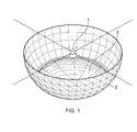
FIG. 1 is illustrating first embodiment of an electromagnetic wave concentrator where a parabolic dish is impeded in a Hemisphere. -
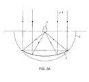
FIG. 2.a is demonstration of one aspect of the first embodiment showing how the parabolic dish impeded in a Hemisphere facing solar beam normally concentrates the beam to the focal point. -
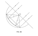
FIG. 2.b is demonstration of the fact that as the Hemisphere inFIG.2.a rotates around its fixed center to track the solar beam and faces it normally, the device will continue to concentrate the solar beam to the fixed focal point. -
FIG.3 illustrates the isometric view of another embodiment of the invention which involves a parabolic reflecting dish along with tracking system with the fixed focal point. -
FIG.4 illustrates a side view of the embodiment shown inFIG.3 with tilt angle between Zero and Ninety degrees. -
FIG.5 illustrates aside view of the embodiment shown inFIG.3 with tilt angle of Ninety degrees. -
FIG.6 illustrates another embodiment of the invention showing an isometric view of a practical design for a concentrating lens tracking system with a Fixed Focal point. - The particular values and configurations discussed in these non-limiting examples can be varied and are cited merely to illustrate at least one embodiment and are not intended to limit the scope thereof.
- The present invention illustrates methods and apparatus for concentrating electromagnetic waves originating from a moving source to a fixed focal point by using an electromagnetic wave concentrating device, such as a reflecting parabolic dish or a concentrating lens which concentrates incoming normal electromagnetic waves to its focal point and impeding such device into a hemisphere(which can be real or imaginary) such that its focal point coincides with the centre of the hemisphere. The hemisphere can rotate about its fixed centre and this apparatus can track a moving electromagnetic wave source by rotating around said hemisphere's fixed centre, so as to face the incoming electromagnetic rays normally. Hence, if the hemisphere is rotated around its center while facing the electromagnetic wave (or the incoming signal) normally, the device will always concentrate the beam to the focal point fixed with respect to ground. The exemplary embodiments of the present invention are described by taking parabolic dish and lens as examples of the optical devices. The parabolic dish or lens impeded in the hemisphere always focus the solar beam, telecommunication signals and other electromagnetic wave fronts on a focal point fixed to the ground.
- In one embodiment of the invention as shown in
FIG. 1 , a parabolic dish (3) is impeded in a hemisphere. The focal point of the parabolic dish coincides with the center of the sphere (1) where the hemisphere is actually half of the sphere. Hereafter, center of the sphere will be referred to as the center of the hemisphere. The center of the hemisphere (1) is at a fixed point to the ground. Therefore regardless of the of the way the hemisphere rotates around its center, the focal point of the parabolic dish remains the same as the center of the sphere (that is fixed to the ground) for any beam that is normal to cross sectional plane of the sphere or the parabolic dish. To concentrate the solar beam, telecommunication signal, and other electromagnetic signals to the receiver, one only needs to rotate the sphere around its center so that the solar beam or the electromagnetic signal is perpendicular to the plane of the center of the hemisphere. -
FIG.2.a is demonstration of one aspect of the first embodiment wherein a solar beam (or electromagnetic signal) (4) is incident normally to the cross sectional area of the Hemisphere (2) and therefore normal to the parabolic dish impeded in hemisphere (3). The parabolic dish will concentrate solar beam to the focal point (1) which coincides with the center of the Hemisphere. - As the solar beam (or electromagnetic signal) changes its direction, the hemisphere will rotate around its center as shown in
Fig.2.b to normally face the beam. Consequently, the beam will be normally facing the parabolic dish which in turn will concentrate it to the focal point that is the same as the center of the Hemisphere. As mentioned this focal point is fixed to the ground. Therefore regardless of the direction of the solar (or signal) beam, the parabolic dish will focus it to the fixed focal point which is also the center of the Hemisphere. All that is needed to rotate the hemisphere around its center to face the solar beam normally to the hemispherical plane or parabolic curvature. The hemisphere can really exist or can be fictional. -
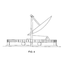
FIG.3 is another embodiment of the present invention showing an isometric view of parabolic dish tracking system with the fixed focal point. In this embodiment, the parabolic dish (3) is held by two arms (2) that are freely joined to a support (6). The two supports (6) are fixed on a platform, preferably, circular platform(7) placed on wheels and rotates either clockwise or counters clockwise as controlled by a side motor (8). This can be a pinion-gear mechanism or a pulley-built mechanism or any other known method of rotation. The rotation of this platform will follow the azimuth angle of the sun. The parabolic Dish (3) supported by the arms (2) is free to swing around the free joints of the supports (6), To control this motion of the parabolic dish, a rope is connected to opposite edge of the dish and other end is wrapped around a platform motor (4) fixed to the circular platform (7).Fig.4 provides a better view of the rope. By pulling or releasing the rope, the platform motor (4) will control the tilt angle of the dish to match that of the sun. Therefore, by rotating the circular platform (7) controlled by the side motor (8) and pulling or releasing the rope controlled by the platform motor (4) the parabolic dish will always be normally facing the sun through any known control mechanism of motors (4) and (8) as discussed. A receiver (1) for example but are not limited to a photo voltaic system, furnace, transceiver, or other electromagnetic wave tracking systems, is located at the focal point of the parabolic dish (3) which is the same of the center of an imaginary Hemisphere. Consequently, as long as the parabolic dish faces the sun normally due to the controls of motors (4) and (8), the sun will always be concentrated on the fixed focal point at the receiver (1). The receiver is supported on the ground by a support (5) having a passageway, which is circulating a material to the receiver and/ or from it. The material can be a fluid to move the turbine for example but are not limited to combined cycle gas turbine etc. Instead of burning fuel to increase the compressed air temperature in the burning chamber, the compressed air is allowed to flow to the fixed location focal point to be heated to the high temperatures and then flow back to turbine stage. This heated air is further used to boil the water to steam to run the steam turbine. This will result in a very high efficiency solar electricity generation. The passage can also be used for circulating materials for example metals and non metals. For continuous metal melting, the support can also contain passages for uploading the solid metal to the receiver and allowing for the melted metal to flow away from the receiver, The high temperature resulting in a fixed point by the methods described can also be used for thermal hydrogen generation from water and other thermo chemical storage applications of solar energy. The Parabolic Dish (3) has a slot slightly larger than the dimensions of support (5) allowing it to swing freely as clearly demonstrated inFig.3 . Furthermore, the receiver can be forced to always face the dish if needed by placing it on a three dimensional pivot (9) and connected to the rod (10) that rotates with the tilt angle of the dish. This will guarantee that the receiver will always normally receive the concentrated solar beam, the telecommunication signal, or any other electromagnetic signal. This is especially important for certain cases such as if the receiver is a Sterling Engine. On the other hand, the support can also be from the top of the dish rather from the bottom for any needed applications. -
FIG.4 is a side view of the isometric shown inFIG.3 with tilt angle between Zero and Ninety degrees. -
FIG.5 is a side view of the isometric shown inFIG.3 with tilt angle of Ninety degrees and it can be easily imagined the position of the system when the sun is normal to the ground. -
FIG.6 is another embodiment of the invention showing an isometric view of a practical design for a concentrating lens tracking system with a fixed focal point. In many cases solar beams need to be concentrated from above to a receiver in the bottom. In that case a concentrating lens is used. The lens can either be smoothed or Fresnel lens. An electromagnetic wave concentrating system similar to the one described for the parabolic dish is shown inFig. 6 . Similar to what was described inFig.3 earlier, receiver (1), connecting arms (2), rope controlling platform motor (4), receiver support (5), supports (6), platform (7) and side motor (8) are the same as that were described earlier with the same function. However, the parabolic Dish (3) inFig.3 that swings from under the receiver (1) is replaced with a concentrating lens (3) inFig. 6 that swings above the receiver concentrating the solar beam directly on it. The location of motor (4) inFig.6 is different from its location inFig.3 ,fig.4 , andFig.5 . As motors (4) and (8) inFig.6 control the position of the lens to be always normal to the solar beam, the lens will concentrate the sun on the receiver (1) at the fixed focal point. Similarly receiver (1) can either be rigid or be pivoted on a three dimensional pivot to force it to normally face the concentrating lens. - The Tracking System and apparatus illustrated in the present invention built for the electromagnetic wave concentration device, such as but not limited to reflecting Parabolic Dish Concentrator or Concentrating Lens, which maintains fixed focal point has many applications that cannot be obtained conventionally. For solar applications the methods described in
Fig.3 andFig.4 allow for continuous metal melting as the support can also contain passages for uploading the solid metal to the receiver and allowing for the melted metal to flow away from the receiver. Another important application is that these methods can be used for combined cycle gas turbine. Instead of burning fuel to increase the compressed air temperature in the burning chamber, the compressed air is allowed to flow to the fixed location focal point to be heated to the high temperatures and then flow back to turbine stage and as it exhausting a steam can be boiled similar to any combined cycle steam turbine. This will result in a very high efficiency solar electricity generation. The high temperature resulting in a fixed point by the methods described can also be used for thermal hydrogen generation from water and other thermo chemical storage applications of solar energy. Furthermore, since the focal point can be supported in this invention the current tracking parabolic dish can be used for large scale power generation using heavy sterling engine which was not feasible in a moving focal point system. - It will be appreciated that variations of the above disclosed and other features and functions, or alternatives thereof, may be desirably combined into many other different systems or applications. Also that various presently unforeseen or unanticipated alternatives, modifications, variations or improvements therein may be subsequently made by those skilled in the art which are also intended to be encompassed by the following claims.
Claims (23)
- A method for concentrating electromagnetic waves originating from a moving source to a fixed focal point, comprising of:A electromagnetic wave concentrating device which concentrates incoming normal electromagnetic waves to its focal point:A hemisphere capable of rotating about its fixed center;impeding such electromagnetic wave concentrating device in the said hemisphere such that its focal point coincides with the center of the hemisphere;and using this apparatus to track such moving source by rotating around said hemisphere's fixed center, so as to face the incoming electromagnetic rays normally.
- The method of claim 1 where the said hemisphere is imaginary and the electromagnetic wave concentrating device rotates around said imaginary hemisphere's center so as to keep its focal point fixed to the ground.
- The method of claim 1 wherein a receiver is fixed at the focal point of the said electromagnetic wave concentrating device and which makes use of the concentrated electromagnetic waves.
- The method of claim 3, wherein the said receiver is fixed on a support fixed to a platform holding the electromagnetic wave concentrator and where the support is provided with a passageway for circulating a material to or from the receiver.
- The method of claim 4, wherein an arm is freely joined to the support and attached to the said electromagnetic wave concentrating device to enable such device to swing around the joint of such support.
- The method of claim 4, wherein a side motor is controlling the rotation of the platform by any one of the mechanisms selected from a group comprising of a pinion-gear mechanism, a pulley-built mechanism or any other known method of rotation.
- The method of claim 6, wherein the rotation of the platform is controlled to follow the azimuth angle of the sun.
- An apparatus for concentrating electromagnetic waves originating from a moving source to a fixed focal point, comprising of:A hemisphere capable of rotating about its fixed centre;A electromagnetic wave concentrating device which concentrates incoming normal electromagnetic waves to its focal point; impededin the said hemisphere such that its focal point coincides with the centre of the hemisphere;
- The apparatus of claim 8, wherein the said hemisphere is imaginary and the electromagnetic wave concentrating device rotates around said imaginary hemisphere's centre so as to keep its focal point fixed to the ground.
- The apparatus of claim 8, wherein the said electromagnetic wave concentrating device concentrates the incoming electromagnetic waves either by reflection such as a parabolic reflecting dish or by refraction such as a concentrating lens.
- The apparatus of claim 8, wherein a receiver is fixed at the focal point of the said electromagnetic wave concentrating device and which makes use of the concentrated electromagnetic waves.
- The apparatus of claim 11, wherein the said receiver is placed along a three dimensional pivot that rotates with the tilt angle of the said electromagnetic wave concentrating device to receive the concentrated electromagnetic waves in a normal direction.
- The apparatus of claim 11, wherein the said receiver is fixed on a support fixed to a platform holding the electromagnetic wave concentrator and where the support is provided with a passageway for circulating a material to or from the receiver.
- The apparatus of claim 13, whereinan arm is freely joined to the support and attached to thethe said electromagnetic wave concentrating device to enable such device to swing around the joint of such support.
- The apparatus of claim 13, wherein a slot slightly larger than the dimensions of the support is provided in the said electromagnetic wave concentrating device for allowing the optical device to swing freely.
- The apparatus of claim 13, wherein a side motor is controlling the rotation of the platform by any one of the mechanisms selected from a group comprising of a pinion-gear mechanism, a pulley-built mechanism or any other known method of rotation.
- The apparatus of claim 16, wherein the rotation of the platform is controlled to follow the azimuth angle of the sun.
- The apparatus of claim 13, wherein a rope is connected to opposite edge of the said electromagnetic wave concentrating device and wrapped around a platform motor fixed to the platform.
- The apparatus of claim 18, wherein by pulling or releasing the rope, the platform motor controls the tilt angle of the said electromagnetic wave concentratingdevice to normally face the sun.
- The apparatus of claim 11, wherein the receiver forms a smelter of metal heated by the concentrated rays and where metal flows into the smelter through a conveyor belt and the melted liquid metal flows down through another passage in the support of the receiver.
- The apparatus of claim 11, wherein the receiver is the combustion chamber of a combined cycle gas turbine raising the compressed air temperature after the compressor stage by passing it through the receiver to be heated by the concentrated rays.
- The apparatus of claim 11, wherein the receiver is a heavy Sterling Engine.
- The apparatus of claim 11, wherein the receiver is the hot receiver part of hydrogen generator of water splitting device into hydrogen and oxygen thermally.
Priority Applications (1)
| Application Number | Priority Date | Filing Date | Title |
|---|---|---|---|
| RS20240434A RS65423B1 (en) | 2014-04-28 | 2015-04-21 | Method and apparatus for tracking and concentrating electromagnetic waves coming from a moving source to a fixed focal point |
Applications Claiming Priority (1)
| Application Number | Priority Date | Filing Date | Title |
|---|---|---|---|
| US14/262,985 US9772121B1 (en) | 2014-04-28 | 2014-04-28 | Method and apparatus for tracking and concentrating electromagnetic waves coming from a moving source to a fixed focal point |
Publications (4)
| Publication Number | Publication Date |
|---|---|
| EP2944894A2 true EP2944894A2 (en) | 2015-11-18 |
| EP2944894A3 EP2944894A3 (en) | 2016-01-20 |
| EP2944894B1 EP2944894B1 (en) | 2024-02-28 |
| EP2944894C0 EP2944894C0 (en) | 2024-02-28 |
Family
ID=53039156
Family Applications (1)
| Application Number | Title | Priority Date | Filing Date |
|---|---|---|---|
| EP15001170.8A Active EP2944894B1 (en) | 2014-04-28 | 2015-04-21 | Method and apparatus for tracking and concentrating electromagnetic waves coming from a moving source to a fixed focal point |
Country Status (5)
| Country | Link |
|---|---|
| US (1) | US9772121B1 (en) |
| EP (1) | EP2944894B1 (en) |
| ES (1) | ES2977407T3 (en) |
| RS (1) | RS65423B1 (en) |
| WO (1) | WO2015167851A1 (en) |
Cited By (1)
| Publication number | Priority date | Publication date | Assignee | Title |
|---|---|---|---|---|
| EP3717772A4 (en) * | 2017-07-21 | 2021-10-27 | Wahaj Investment LLC | RADIANT ENERGY COLLECTION SYSTEM USING A SOLAR CONCENTRATOR WITHOUT IMAGING |
Families Citing this family (1)
| Publication number | Priority date | Publication date | Assignee | Title |
|---|---|---|---|---|
| CN115289693B (en) * | 2022-01-21 | 2025-09-02 | 哈尔滨瀚成科技有限公司 | A solar direct heating device |
Family Cites Families (35)
| Publication number | Priority date | Publication date | Assignee | Title |
|---|---|---|---|---|
| US3998206A (en) * | 1973-08-31 | 1976-12-21 | Arnold Jahn | System for collecting and utilizing solar energy |
| CH597574A5 (en) * | 1976-01-29 | 1978-04-14 | Roger Lang | |
| US4111184A (en) | 1977-04-06 | 1978-09-05 | Nasa | Sun tracking solar energy collector |
| US4252107A (en) * | 1978-04-20 | 1981-02-24 | General Electric Company | Solar tracking concentrator |
| FR2446451B1 (en) * | 1979-01-09 | 1987-10-02 | Lassalle Eliane | FIXED FIREPLACE SOLAR OVEN |
| US4449515A (en) | 1979-07-16 | 1984-05-22 | Seige Corporation | Apparatus for collecting, intensifying and storing solar energy |
| US4333446A (en) * | 1980-05-16 | 1982-06-08 | Smyth Aerodynamics, Inc. | Solar concentrator |
| US4781174A (en) * | 1982-12-08 | 1988-11-01 | Gardner Kenneth H | Cremation apparatus and method |
| US4548195A (en) | 1983-12-27 | 1985-10-22 | Balhorn Alan C | Solar energy apparatus with automatic tracking alignment adjustments |
| US4586334A (en) * | 1985-01-23 | 1986-05-06 | Nilsson Sr Jack E | Solar energy power generation system |
| DE3611375A1 (en) * | 1986-04-03 | 1987-10-08 | Rosskoth Kathrin | Solar cooking (boiling) apparatus |
| US4870949A (en) * | 1987-07-27 | 1989-10-03 | Butler Barry L | Wind resistant two axis tracker for energy or radiation concertrators |
| US4875467A (en) * | 1988-07-28 | 1989-10-24 | The United States Of America As Represented By The United States Department Of Energy | Support and maneuvering apparatus for solar energy receivers |
| US5325844A (en) | 1992-02-11 | 1994-07-05 | Power Kinetics, Inc. | Lightweight, distributed force, two-axis tracking, solar radiation collector structures |
| WO2003004942A1 (en) * | 2001-07-05 | 2003-01-16 | Paul Scherrer Institut | Reactor for using solar radiant heat |
| IL155867A0 (en) * | 2003-05-12 | 2003-12-23 | Univ Ramot | Solar tracking system |
| US7637457B2 (en) * | 2004-04-30 | 2009-12-29 | Lawrence Livermore National Security, Llc | Rankine-Brayton engine powered solar thermal aircraft |
| WO2006108247A1 (en) * | 2005-04-11 | 2006-10-19 | Bakir Krupic | Rotary concave mirror for production of hot water or water steam |
| US20080184989A1 (en) * | 2005-11-14 | 2008-08-07 | Mecham Travis W | Solar blackbody waveguide for high pressure and high temperature applications |
| DE102006044601A1 (en) * | 2006-09-19 | 2008-03-27 | Solar Dynamics Gmbh | spherical optics |
| FR2927155B1 (en) * | 2007-03-05 | 2010-04-02 | R & D Ind Sarl | SOLAR CAPTOR. |
| US8272216B2 (en) * | 2008-02-22 | 2012-09-25 | Toyota Jidosha Kabushiki Kaisha | Method for converting solar thermal energy |
| US20090314280A1 (en) | 2008-06-24 | 2009-12-24 | Rajarshi Banerjee | Apparatus and A Method for Solar Tracking and Concentration af Incident Solar Radiation for Power Generation |
| US20100000874A1 (en) | 2008-06-24 | 2010-01-07 | Sundrop Fuels, Inc. | Various methods and apparatus for solar assisted fuel production |
| CN102282430B (en) * | 2009-02-03 | 2014-08-20 | 益科博能源科技有限公司 | Systems and methods of solar thermal concentration for 2-dimensional focusing concentrators |
| US8069849B2 (en) * | 2009-02-13 | 2011-12-06 | Matalon Energy, Llc | Parabolic solar collector |
| US8166966B2 (en) * | 2009-06-24 | 2012-05-01 | Detch John W | Dish reflector concentrator structure |
| US20110186041A1 (en) * | 2010-02-03 | 2011-08-04 | Kalex, Llc | Apparatus for pivoting solar troughs on a central axis |
| WO2011130695A2 (en) | 2010-04-15 | 2011-10-20 | Axisol Inc. | Solar collectors |
| US8705917B2 (en) * | 2010-07-21 | 2014-04-22 | Jorge A Garza | Solar energy device |
| WO2012017078A2 (en) * | 2010-08-06 | 2012-02-09 | Alstom Technology Ltd | Solar tower with integrated gas turbine |
| US20120266938A1 (en) * | 2011-04-25 | 2012-10-25 | Aspect Solar Pte Ltd | Solar tracking system and method for concentrated photovoltaic (cpv) systems |
| US9335015B2 (en) | 2012-01-23 | 2016-05-10 | 3M Innovative Properties Company | Off-axis cassegrain solar collector |
| US9347690B2 (en) * | 2012-04-02 | 2016-05-24 | Alliance For Sustainable Energy, Llc | Methods and systems for concentrated solar power |
| US9689586B2 (en) | 2013-03-05 | 2017-06-27 | Thermal Storage Systems | System and method for collecting solar energy with a stationary thermal storage device |
-
2014
- 2014-04-28 US US14/262,985 patent/US9772121B1/en active Active - Reinstated
-
2015
- 2015-04-21 EP EP15001170.8A patent/EP2944894B1/en active Active
- 2015-04-21 WO PCT/US2015/026763 patent/WO2015167851A1/en not_active Ceased
- 2015-04-21 RS RS20240434A patent/RS65423B1/en unknown
- 2015-04-21 ES ES15001170T patent/ES2977407T3/en active Active
Non-Patent Citations (1)
| Title |
|---|
| None |
Cited By (1)
| Publication number | Priority date | Publication date | Assignee | Title |
|---|---|---|---|---|
| EP3717772A4 (en) * | 2017-07-21 | 2021-10-27 | Wahaj Investment LLC | RADIANT ENERGY COLLECTION SYSTEM USING A SOLAR CONCENTRATOR WITHOUT IMAGING |
Also Published As
| Publication number | Publication date |
|---|---|
| EP2944894B1 (en) | 2024-02-28 |
| WO2015167851A1 (en) | 2015-11-05 |
| RS65423B1 (en) | 2024-05-31 |
| US9772121B1 (en) | 2017-09-26 |
| EP2944894C0 (en) | 2024-02-28 |
| EP2944894A3 (en) | 2016-01-20 |
| ES2977407T3 (en) | 2024-08-23 |
Similar Documents
| Publication | Publication Date | Title |
|---|---|---|
| El Gharbi et al. | A comparative study between parabolic trough collector and linear Fresnel reflector technologies | |
| Zhu et al. | History, current state, and future of linear Fresnel concentrating solar collectors | |
| US9476612B2 (en) | Beam-forming concentrating solar thermal array power systems | |
| AU2011101778A4 (en) | Solar heat collecting system | |
| CN101852499B (en) | Disc type focusing device capable of adjusting focusing ratio | |
| US9140468B2 (en) | Solar power unit | |
| Thakkar et al. | Performance analysis methodology for parabolic dish solar concentrators for process heating using thermic fluid | |
| Roldán Serrano | Concentrating solar thermal technologies | |
| US20100154866A1 (en) | Hybrid solar power system | |
| US20130098354A1 (en) | Solar collectors | |
| WO2015037230A1 (en) | Heliostat device, solar thermal collection device, and solar concentrating photovoltaic device | |
| Sahu et al. | Historical overview of power generation in solar parabolic dish collector system | |
| EP2944894B1 (en) | Method and apparatus for tracking and concentrating electromagnetic waves coming from a moving source to a fixed focal point | |
| US20140299121A1 (en) | Radiation collection utilizing total internal reflection and other techniques for the purpose of dispatchable electricity generation and other uses | |
| US10436182B2 (en) | System for collecting radiant energy with a non-imaging solar concentrator | |
| CN101915985A (en) | A dish-type solar focusing device with fixed focus | |
| EP3221650B1 (en) | Solar concentrator with spaced pivotable connections | |
| CN201652878U (en) | Fixed eyepiece solar heat collection system | |
| Groulx et al. | Ray-tracing analysis of a two-stage solar concentrator | |
| Idlimam et al. | Impact of the parabolic solar concentrator’s rim angle on the quantity of reflected rays and concentrated flux on the receiver | |
| Jin | Concentrated Solar Power Generation | |
| Tibúrcio | Solar Tracking Error in Solar-Pumped Lasers | |
| WO2012107104A1 (en) | Solar collection system | |
| WO2026043846A1 (en) | Apparatus and method for high solar concentration using a field of twisting heliostats | |
| JP2008052229A (en) | New collective mirror composed of annular parabolic mirror with different focal length |
Legal Events
| Date | Code | Title | Description |
|---|---|---|---|
| PUAI | Public reference made under article 153(3) epc to a published international application that has entered the european phase |
Free format text: ORIGINAL CODE: 0009012 |
|
| 17P | Request for examination filed |
Effective date: 20150430 |
|
| AK | Designated contracting states |
Kind code of ref document: A2 Designated state(s): AL AT BE BG CH CY CZ DE DK EE ES FI FR GB GR HR HU IE IS IT LI LT LU LV MC MK MT NL NO PL PT RO RS SE SI SK SM TR |
|
| AX | Request for extension of the european patent |
Extension state: BA ME |
|
| PUAL | Search report despatched |
Free format text: ORIGINAL CODE: 0009013 |
|
| AK | Designated contracting states |
Kind code of ref document: A3 Designated state(s): AL AT BE BG CH CY CZ DE DK EE ES FI FR GB GR HR HU IE IS IT LI LT LU LV MC MK MT NL NO PL PT RO RS SE SI SK SM TR |
|
| AX | Request for extension of the european patent |
Extension state: BA ME |
|
| RIC1 | Information provided on ipc code assigned before grant |
Ipc: F24J 2/08 20060101ALI20151217BHEP Ipc: F24J 2/54 20060101ALI20151217BHEP Ipc: F24J 2/02 20060101AFI20151217BHEP Ipc: F24J 2/12 20060101ALI20151217BHEP |
|
| STAA | Information on the status of an ep patent application or granted ep patent |
Free format text: STATUS: EXAMINATION IS IN PROGRESS |
|
| 17Q | First examination report despatched |
Effective date: 20180627 |
|
| RAP1 | Party data changed (applicant data changed or rights of an application transferred) |
Owner name: WAHAJ INVESTMENT LLC |
|
| RIN1 | Information on inventor provided before grant (corrected) |
Inventor name: AL-MAAITAH, ADNAN AYMAN |
|
| REG | Reference to a national code |
Ref country code: DE Ref legal event code: R079 Free format text: PREVIOUS MAIN CLASS: F24J0002020000 Ref country code: DE Ref legal event code: R079 Ref document number: 602015087684 Country of ref document: DE Free format text: PREVIOUS MAIN CLASS: F24J0002020000 Ipc: F24S0020300000 |
|
| RIC1 | Information provided on ipc code assigned before grant |
Ipc: F24S 30/00 20180101ALI20230622BHEP Ipc: F24S 50/20 20180101ALI20230622BHEP Ipc: F24S 50/00 20180101ALI20230622BHEP Ipc: F24S 30/452 20180101ALI20230622BHEP Ipc: F03G 6/06 20060101ALI20230622BHEP Ipc: F24S 30/40 20180101ALI20230622BHEP Ipc: F24S 23/30 20180101ALI20230622BHEP Ipc: F24S 23/71 20180101ALI20230622BHEP Ipc: F24S 20/30 20180101AFI20230622BHEP |
|
| GRAP | Despatch of communication of intention to grant a patent |
Free format text: ORIGINAL CODE: EPIDOSNIGR1 |
|
| STAA | Information on the status of an ep patent application or granted ep patent |
Free format text: STATUS: GRANT OF PATENT IS INTENDED |
|
| INTG | Intention to grant announced |
Effective date: 20230918 |
|
| GRAS | Grant fee paid |
Free format text: ORIGINAL CODE: EPIDOSNIGR3 |
|
| GRAA | (expected) grant |
Free format text: ORIGINAL CODE: 0009210 |
|
| STAA | Information on the status of an ep patent application or granted ep patent |
Free format text: STATUS: THE PATENT HAS BEEN GRANTED |
|
| AK | Designated contracting states |
Kind code of ref document: B1 Designated state(s): AL AT BE BG CH CY CZ DE DK EE ES FI FR GB GR HR HU IE IS IT LI LT LU LV MC MK MT NL NO PL PT RO RS SE SI SK SM TR |
|
| REG | Reference to a national code |
Ref country code: GB Ref legal event code: FG4D |
|
| REG | Reference to a national code |
Ref country code: CH Ref legal event code: EP |
|
| REG | Reference to a national code |
Ref country code: DE Ref legal event code: R096 Ref document number: 602015087684 Country of ref document: DE |
|
| REG | Reference to a national code |
Ref country code: IE Ref legal event code: FG4D |
|
| U01 | Request for unitary effect filed |
Effective date: 20240327 |
|
| U07 | Unitary effect registered |
Designated state(s): AT BE BG DE DK EE FI FR IT LT LU LV MT NL PT SE SI Effective date: 20240404 |
|
| REG | Reference to a national code |
Ref country code: GR Ref legal event code: EP Ref document number: 20240400953 Country of ref document: GR Effective date: 20240516 |
|
| U20 | Renewal fee for the european patent with unitary effect paid |
Year of fee payment: 10 Effective date: 20240429 |
|
| PG25 | Lapsed in a contracting state [announced via postgrant information from national office to epo] |
Ref country code: IS Free format text: LAPSE BECAUSE OF FAILURE TO SUBMIT A TRANSLATION OF THE DESCRIPTION OR TO PAY THE FEE WITHIN THE PRESCRIBED TIME-LIMIT Effective date: 20240628 |
|
| PG25 | Lapsed in a contracting state [announced via postgrant information from national office to epo] |
Ref country code: HR Free format text: LAPSE BECAUSE OF FAILURE TO SUBMIT A TRANSLATION OF THE DESCRIPTION OR TO PAY THE FEE WITHIN THE PRESCRIBED TIME-LIMIT Effective date: 20240228 |
|
| PG25 | Lapsed in a contracting state [announced via postgrant information from national office to epo] |
Ref country code: NO Free format text: LAPSE BECAUSE OF FAILURE TO SUBMIT A TRANSLATION OF THE DESCRIPTION OR TO PAY THE FEE WITHIN THE PRESCRIBED TIME-LIMIT Effective date: 20240528 Ref country code: IS Free format text: LAPSE BECAUSE OF FAILURE TO SUBMIT A TRANSLATION OF THE DESCRIPTION OR TO PAY THE FEE WITHIN THE PRESCRIBED TIME-LIMIT Effective date: 20240628 Ref country code: HR Free format text: LAPSE BECAUSE OF FAILURE TO SUBMIT A TRANSLATION OF THE DESCRIPTION OR TO PAY THE FEE WITHIN THE PRESCRIBED TIME-LIMIT Effective date: 20240228 |
|
| PG25 | Lapsed in a contracting state [announced via postgrant information from national office to epo] |
Ref country code: PL Free format text: LAPSE BECAUSE OF FAILURE TO SUBMIT A TRANSLATION OF THE DESCRIPTION OR TO PAY THE FEE WITHIN THE PRESCRIBED TIME-LIMIT Effective date: 20240228 |
|
| REG | Reference to a national code |
Ref country code: ES Ref legal event code: FG2A Ref document number: 2977407 Country of ref document: ES Kind code of ref document: T3 Effective date: 20240823 |
|
| PG25 | Lapsed in a contracting state [announced via postgrant information from national office to epo] |
Ref country code: PL Free format text: LAPSE BECAUSE OF FAILURE TO SUBMIT A TRANSLATION OF THE DESCRIPTION OR TO PAY THE FEE WITHIN THE PRESCRIBED TIME-LIMIT Effective date: 20240228 |
|
| PG25 | Lapsed in a contracting state [announced via postgrant information from national office to epo] |
Ref country code: SM Free format text: LAPSE BECAUSE OF FAILURE TO SUBMIT A TRANSLATION OF THE DESCRIPTION OR TO PAY THE FEE WITHIN THE PRESCRIBED TIME-LIMIT Effective date: 20240228 |
|
| PG25 | Lapsed in a contracting state [announced via postgrant information from national office to epo] |
Ref country code: CZ Free format text: LAPSE BECAUSE OF FAILURE TO SUBMIT A TRANSLATION OF THE DESCRIPTION OR TO PAY THE FEE WITHIN THE PRESCRIBED TIME-LIMIT Effective date: 20240228 |
|
| PG25 | Lapsed in a contracting state [announced via postgrant information from national office to epo] |
Ref country code: SK Free format text: LAPSE BECAUSE OF FAILURE TO SUBMIT A TRANSLATION OF THE DESCRIPTION OR TO PAY THE FEE WITHIN THE PRESCRIBED TIME-LIMIT Effective date: 20240228 |
|
| PG25 | Lapsed in a contracting state [announced via postgrant information from national office to epo] |
Ref country code: SM Free format text: LAPSE BECAUSE OF FAILURE TO SUBMIT A TRANSLATION OF THE DESCRIPTION OR TO PAY THE FEE WITHIN THE PRESCRIBED TIME-LIMIT Effective date: 20240228 Ref country code: SK Free format text: LAPSE BECAUSE OF FAILURE TO SUBMIT A TRANSLATION OF THE DESCRIPTION OR TO PAY THE FEE WITHIN THE PRESCRIBED TIME-LIMIT Effective date: 20240228 Ref country code: RO Free format text: LAPSE BECAUSE OF FAILURE TO SUBMIT A TRANSLATION OF THE DESCRIPTION OR TO PAY THE FEE WITHIN THE PRESCRIBED TIME-LIMIT Effective date: 20240228 Ref country code: CZ Free format text: LAPSE BECAUSE OF FAILURE TO SUBMIT A TRANSLATION OF THE DESCRIPTION OR TO PAY THE FEE WITHIN THE PRESCRIBED TIME-LIMIT Effective date: 20240228 |
|
| PG25 | Lapsed in a contracting state [announced via postgrant information from national office to epo] |
Ref country code: MC Free format text: LAPSE BECAUSE OF FAILURE TO SUBMIT A TRANSLATION OF THE DESCRIPTION OR TO PAY THE FEE WITHIN THE PRESCRIBED TIME-LIMIT Effective date: 20240228 |
|
| PG25 | Lapsed in a contracting state [announced via postgrant information from national office to epo] |
Ref country code: MC Free format text: LAPSE BECAUSE OF FAILURE TO SUBMIT A TRANSLATION OF THE DESCRIPTION OR TO PAY THE FEE WITHIN THE PRESCRIBED TIME-LIMIT Effective date: 20240228 |
|
| REG | Reference to a national code |
Ref country code: DE Ref legal event code: R097 Ref document number: 602015087684 Country of ref document: DE Ref country code: CH Ref legal event code: PL |
|
| PLBE | No opposition filed within time limit |
Free format text: ORIGINAL CODE: 0009261 |
|
| STAA | Information on the status of an ep patent application or granted ep patent |
Free format text: STATUS: NO OPPOSITION FILED WITHIN TIME LIMIT |
|
| PG25 | Lapsed in a contracting state [announced via postgrant information from national office to epo] |
Ref country code: CH Free format text: LAPSE BECAUSE OF NON-PAYMENT OF DUE FEES Effective date: 20240430 |
|
| 26N | No opposition filed |
Effective date: 20241129 |
|
| PG25 | Lapsed in a contracting state [announced via postgrant information from national office to epo] |
Ref country code: IE Free format text: LAPSE BECAUSE OF NON-PAYMENT OF DUE FEES Effective date: 20240421 |
|
| PG25 | Lapsed in a contracting state [announced via postgrant information from national office to epo] |
Ref country code: CH Free format text: LAPSE BECAUSE OF NON-PAYMENT OF DUE FEES Effective date: 20240430 |
|
| PGRI | Patent reinstated in contracting state [announced from national office to epo] |
Ref country code: CH Effective date: 20250123 |
|
| U20 | Renewal fee for the european patent with unitary effect paid |
Year of fee payment: 11 Effective date: 20250428 |
|
| PGFP | Annual fee paid to national office [announced via postgrant information from national office to epo] |
Ref country code: GB Payment date: 20250428 Year of fee payment: 11 Ref country code: ES Payment date: 20250505 Year of fee payment: 11 |
|
| PGFP | Annual fee paid to national office [announced via postgrant information from national office to epo] |
Ref country code: RS Payment date: 20250402 Year of fee payment: 11 |
|
| PGFP | Annual fee paid to national office [announced via postgrant information from national office to epo] |
Ref country code: GR Payment date: 20250430 Year of fee payment: 11 |
|
| PGFP | Annual fee paid to national office [announced via postgrant information from national office to epo] |
Ref country code: CH Payment date: 20250501 Year of fee payment: 11 |
|
| PGFP | Annual fee paid to national office [announced via postgrant information from national office to epo] |
Ref country code: TR Payment date: 20250418 Year of fee payment: 11 |
|
| PG25 | Lapsed in a contracting state [announced via postgrant information from national office to epo] |
Ref country code: HU Free format text: LAPSE BECAUSE OF FAILURE TO SUBMIT A TRANSLATION OF THE DESCRIPTION OR TO PAY THE FEE WITHIN THE PRESCRIBED TIME-LIMIT; INVALID AB INITIO Effective date: 20150421 |
|
| PGFP | Annual fee paid to national office [announced via postgrant information from national office to epo] |
Ref country code: CY Payment date: 20250407 Year of fee payment: 11 |