EP2944835A1 - Attachment assembly - Google Patents
Attachment assembly Download PDFInfo
- Publication number
- EP2944835A1 EP2944835A1 EP15153539.0A EP15153539A EP2944835A1 EP 2944835 A1 EP2944835 A1 EP 2944835A1 EP 15153539 A EP15153539 A EP 15153539A EP 2944835 A1 EP2944835 A1 EP 2944835A1
- Authority
- EP
- European Patent Office
- Prior art keywords
- screw
- retaining element
- bore
- attachment assembly
- shaft
- Prior art date
- Legal status (The legal status is an assumption and is not a legal conclusion. Google has not performed a legal analysis and makes no representation as to the accuracy of the status listed.)
- Granted
Links
Images




Classifications
-
- F—MECHANICAL ENGINEERING; LIGHTING; HEATING; WEAPONS; BLASTING
- F16—ENGINEERING ELEMENTS AND UNITS; GENERAL MEASURES FOR PRODUCING AND MAINTAINING EFFECTIVE FUNCTIONING OF MACHINES OR INSTALLATIONS; THERMAL INSULATION IN GENERAL
- F16B—DEVICES FOR FASTENING OR SECURING CONSTRUCTIONAL ELEMENTS OR MACHINE PARTS TOGETHER, e.g. NAILS, BOLTS, CIRCLIPS, CLAMPS, CLIPS OR WEDGES; JOINTS OR JOINTING
- F16B41/00—Measures against loss of bolts, nuts, or pins; Measures against unauthorised operation of bolts, nuts or pins
- F16B41/002—Measures against loss of bolts, nuts or pins
-
- B—PERFORMING OPERATIONS; TRANSPORTING
- B60—VEHICLES IN GENERAL
- B60R—VEHICLES, VEHICLE FITTINGS, OR VEHICLE PARTS, NOT OTHERWISE PROVIDED FOR
- B60R21/00—Arrangements or fittings on vehicles for protecting or preventing injuries to occupants or pedestrians in case of accidents or other traffic risks
- B60R21/02—Occupant safety arrangements or fittings, e.g. crash pads
- B60R21/16—Inflatable occupant restraints or confinements designed to inflate upon impact or impending impact, e.g. air bags
- B60R21/20—Arrangements for storing inflatable members in their non-use or deflated condition; Arrangement or mounting of air bag modules or components
- B60R21/213—Arrangements for storing inflatable members in their non-use or deflated condition; Arrangement or mounting of air bag modules or components in vehicle roof frames or pillars
-
- F—MECHANICAL ENGINEERING; LIGHTING; HEATING; WEAPONS; BLASTING
- F16—ENGINEERING ELEMENTS AND UNITS; GENERAL MEASURES FOR PRODUCING AND MAINTAINING EFFECTIVE FUNCTIONING OF MACHINES OR INSTALLATIONS; THERMAL INSULATION IN GENERAL
- F16B—DEVICES FOR FASTENING OR SECURING CONSTRUCTIONAL ELEMENTS OR MACHINE PARTS TOGETHER, e.g. NAILS, BOLTS, CIRCLIPS, CLAMPS, CLIPS OR WEDGES; JOINTS OR JOINTING
- F16B37/00—Nuts or like thread-engaging members
- F16B37/005—Nuts or like thread-engaging members into which threads are cut during screwing
Definitions
- the present disclosure relates to an attachment assembly for attaching a second object to a first object.
- the disclosure further relates to a use of the attachment assembly for attaching an automotive part, such as an inflatable curtain arrangement, to a vehicle.
- the disclosure relates to a unit for use in the attachment assembly, a first kit, a second kit, a vehicle, as well as to a method for attaching a second object to a first object.
- Attaching a second object to a first object may sometimes be difficult for one person, since there is a desire to simultaneously hold the second object at a suitable position for fastening to the first object, to hold a fastening member, such as a screw, and to hold a tool used for attaching the fastening member, such as a screw-driver.
- the difficulties are increased if the second object is large and/or heavy. It is also more difficult if there is limited space available for the person doing the work and/or the person is unable to see the position of the attachment.
- a typical situation may be when attaching an object, such as a panel, to a wall or a ceiling of a building, e.g. during construction.
- Another typical situation is during assembly of a vehicle when attaching an automotive part to the vehicle, e.g. when attaching an inflatable curtain arrangement to a cantrail, i.e. the portion of a vehicle body extending between the A, B and/or C pillars at the upper part of the vehicle.
- the inflatable curtain arrangement comprises a curtain-shaped airbag, which is adapted to cover the upper part of a vehicle's side in case of a side impact collision, thereby cushioning the heads of the passengers seated at that side. Since the inflatable curtain arrangement is part of a passenger protection system, it is desired that the fastening member is secured by a predetermined torque.
- Such attachment work may be carried out more easily by two persons, e.g. one person holding the second object in position and the other fastening it by means of the fastening member using the tool.
- Prior art solutions making it possible for one person to attach one object to another include using a temporary fixation of the second object to the first object, e.g. by means of a clamp to the first object or by a stand standing on e.g. the floor and pressing the second object towards the first object. Time is then spent to arrange the temporary fixation and to remove it afterwards.
- Document US 6,851,710 B2 discloses using a clip, which is pushed into a corresponding opening of the vehicle surface thereby attaching an inflatable curtain arrangement to a vehicle.
- a clip is used in combination with a rigid mechanical fastener, illustrated as a bolt.
- the object of the present disclosure is to overcome or ameliorate at least one of the disadvantages of the prior art, or to provide a useful alternative.
- an attachment assembly for attaching a second object to a first object.
- the attachment assembly comprises a screw and a nut.
- the screw has a head and a shaft and at least a portion of the shaft comprises a thread.
- the nut is adapted to be fixedly attached to the first object.
- the nut comprises a bore adapted for receiving the screw.
- the bore has an axial direction and a height along the axial direction.
- the attachment assembly further comprises a retaining element, which is adapted to be positioned at a perimeter of the shaft of the screw.
- the bore comprises an inner wall, at least a portion of the inner wall being adapted for receiving and holding the retaining element at least in the axial direction.
- the bore is unthreaded and the screw is a thread-cutting screw or a thread-forming screw, which is adapted to cooperate with the bore.
- the first object may be a wall or a ceiling of a building.
- the first object may be a body portion of a vehicle, e.g. a cantrail or an A, B or C pillar.
- the second object is typically large and/or heavy, such that it is difficult to handle for one person.
- the second object may be a panel, e.g. a wall panel or ceiling panel.
- the second object may be a panel or an inflatable curtain arrangement.
- the bore may be a through-going axial bore or it may be a blind bore.
- the at least a portion of the inner wall of the bore may have an inner diameter which is less than the outer thread diameter of the screw.
- the screw is intended to be screwed into the nut, which is fixedly attached to the first object to thereby attach the second object to the first object.
- a screw is a fastener capable of being inserted into holes in assembled parts, forming its own thread, and of being tightened or released by torqueing a head of the screw.
- the nut may be fixedly attached to a first substantially plate-shaped portion of the first object, which first portion comprises a first aperture.
- the nut is fixedly attached or attachable to the first portion e.g. by welding or adhesively, such that the nut is aligned with the first aperture, i.e. the bore of the nut is aligned with the first aperture, such that a screw going through the first aperture also can go through the bore.
- the nut may constitute a weld nut.
- the first aperture may be circular, polygonal or have an arbitrary shape. It should be large enough to allow the shaft of screw to pass. Yet, the nut should remain on the upper side of the first portion.
- the user of the attachment assembly can easily ascertain that the retaining element is present, e.g. by looking at the screw or by touching it. This is in comparison to prior art attachment assemblies, wherein a retaining element is instead located in the nut, e.g. inside the bore, which is more difficult to see and/or touch.
- the screw and the nut are manufactured separately from each other. They may also be sold and/or used as separate units, being prepared for later attachment to each other.
- the nut may be delivered as a part of a first kit also comprising the first object, e.g. a cantrail being sent to an assembly plant for vehicles, wherein another automotive part, such as an inflatable curtain arrangement, is attached to the cantrail.
- the screw may be delivered as a separate unit or may be delivered as part of a second kit also comprising the automotive part.
- the retaining element may be delivered mounted to the screw or it may be delivered as a separate unit to be mounted to the screw at the assembly plant.
- the second object e.g. a second substantially plate-shaped portion of it
- a second aperture having a large enough diameter and/or shape for the shaft of the screw to pass.
- the second aperture may be circular, polygonal or have an arbitrary shape.
- the head of the screw has a larger diameter than the shaft, such that the screw is able to retain the second object in place by means of the head.
- a washer may be used adjacent to the head of the screw for retaining the second object.
- the screw is adapted to be pushed into the bore of the nut as far enough for the retaining element to be retained by the portion of the inner wall of the bore, wherein the retaining element is retained in such a way that it can retain the screw, and optionally the second object.
- the attachment assembly may be configured such that the retaining element can carry the weight of the screw.
- the attachment assembly may be configured such that the retaining element can carry the weight of the second object and the screw.
- the attachment may be performed when the second object is in a hanging position.
- the shape, the size, the material, the resiliency and/or the position of the retaining element may be selected in order to achieve the desired weight-carrying capacity.
- a force above a predetermined level e.g. if the second object is going to be exchanged.
- This predetermined level is selected to be high enough to ascertain that under normal conditions the retaining element is strong enough to retain the screw including the weight of the second object.
- the nut may comprise an indentation adapted for receiving and holding the retaining element at least in the axial direction, the indentation forming a portion of the inner wall of the bore.
- an attachment assembly for attaching a second object to a first object.
- the attachment assembly comprises a screw and a nut.
- the screw has a head and a shaft and at least a portion of the shaft comprises a thread.
- the nut is adapted to be fixedly attached to the first object.
- the nut comprises a bore adapted for receiving the screw.
- the bore has an axial direction and a height along the axial direction.
- the attachment assembly further comprises a retaining element, which is adapted to be positioned at a perimeter of the shaft of the screw.
- the nut comprises an indentation adapted for receiving and holding the retaining element at least in the axial direction.
- the screw is adapted to be pushed into the bore of the nut as far enough for the retaining element to reach the indentation, wherein the retaining element is received in such a way that the indentation can retain the screw, and optionally the second object.
- a snap-in function is obtained by the shape and/or resiliency of the retaining element in relation to the indentation.
- the indentation may have a shape corresponding to the shape of the retaining element.
- the pre-defined position is determined by the location of the indentation in the nut and the relative position of the retaining element on the screw. This differs from some prior art attachment assemblies, wherein the screw indeed is retained by the nut, but wherein there is no predefined relative position between the screw and the nut when retained.
- the person pushing the screw into the nut can easily determine that the retaining element has reached the intended position in the indentation without having to see the attachment assembly itself, e.g. by sensing that the retaining element has reached its proper retaining position and/or by an audible "click" being heard.
- the indentation may be located at a perimeter of the bore of the nut. It may be manufactured in the same manufacturing step as the bore.
- the indentation may be located at a first end of the bore, which end is adapted to face the first object. Then the retaining element may be received in a space defined by the indentation and the first object together.
- the indentation may be located within the bore, such that a distance x between the first end of the bore facing the first object and the indentation fulfils 0 ⁇ x ⁇ h, preferably such that 0.1h ⁇ x ⁇ h.
- the space for receiving and retaining the retaining element is independent of the diameter and the shape of the first aperture.
- a main portion of the bore may comprise a substantially flat inner wall having a cylindrical shape.
- the retaining element may then be held by friction to the inner wall and/or by a resilient force resulting from deforming a resilient retaining element.
- the main portion of the bore is the portion intended to cooperate with the screw.
- An end portion of the bore located at the end of the bore facing the first object may have a wider cross-section than the main portion of the bore, which is located further away from the first object.
- the retaining element may be adapted to be positioned in a thread on the shaft of the screw. This will help to hold the retaining element in place on the screw.
- the retaining element may be held by friction to the shaft of the screw, or it may be adhered to the screw by an adhesive.
- the shaft may be provided with a groove, particularly adapted to hold the retaining element.
- the retaining element may be adapted to be fixedly attached to the shaft of the screw, e.g. adhered to the screw by an adhesive or a snap-in function.
- the retaining element may be adapted to be located at or adjacent to an end of the shaft of the screw. However, the retaining element is anyway positioned at the perimeter of the shaft of the screw, such that the retaining element forms part of the perimeter.
- the end of the screw is at the end of the shaft, which end is opposite to the head. The end is hence furthest away from the head.
- the retaining element may comprise, or be constituted by, a ring-shaped member, e.g. a ring with a closed perimeter or a slotted ring, the ring-shaped member having an inner diameter being adapted to cooperate with the shaft of the screw.
- the ring-shaped member preferably has a circular cross-section.
- the inner diameter of the ring-shaped member may be less than an outer thread diameter of the screw and larger than an inner thread diameter of the screw, such that the retaining element may be held in a thread on the screw.
- the retaining element may be resilient, e.g. having a resilient shape and/or comprising a resilient member.
- the retaining element may be resilient in the plane of the retaining element, e.g. by being able to change its diameter.
- the retaining element may be compressible in the radial direction.
- the retaining element may be able to flex out of its plane, e.g. in the axial direction.
- the retaining element may be bendable or foldable in the axial direction. Thereby the effective outer diameter is changed.
- the whole retaining element may be resilient or one or more portions of it may be resilient.
- the retaining element may be adapted to be held by friction and/or by a resilient force to to the at least a portion of the inner wall of the bore.
- the resilient force may result from deforming a resilient retaining element.
- the retaining element may have a somewhat larger diameter than at least the main portion of the bore.
- the retaining element may be an end cap attached to the screw.
- the end cap may be snap-fitted to the screw and/or attached to it by means of an adhesive.
- the screw and the retaining element thus form an integral unit when being handled by the person, performing the attachment.
- the maximum cross-sectional dimension of the end cap may be chosen to be less than the outer thread diameter of the screw but larger than the inner thread diameter of the screw.
- the end cap may comprise at least one protrusion, e.g. one, two, three, four, six or eight, which protrude in a radial direction and ascertain a good contact between the retaining element and the inner wall of the bore.
- the protrusion may also extend in the axial direction of the shaft of the screw. Purely as an example, the protrusion may extend longer in the axial direction of the shaft than a corresponding axial distance between two adjacent threads.
- the protrusion may e.g. extend in the range of 1-5 millimetres.
- the end cap, including any protrusions may be made of an at least somewhat resilient material, such as a polymer.
- the end cap may have a flat outer surface as seen along the axial direction, i.e. it does not comprise any flange, nor any thread.
- the protrusion may have a major extension in the axial direction of the screw.
- the screw may be held by friction between the protrusions and the main portion of the bore. If a cross-sectional dimension through at least one of the protrusions and the axis of the screw is larger than the diameter of the main portion of the bore, the protrusions will be deformed when pushing the screw into the bore. The protrusions then strive to go back to their original shape resulting in a resilient force contributing to holding the screw in the intended place.
- This kind of retaining element is appropriate for a bore having a flat inner wall. There is no need for an indentation or any thread in the bore in order to retain the screw. There may also be a resilient force resulting from the retaining element itself having a larger diameter than the diameter of the main portion of the bore. In that case the protrusions may be dispensed with. The retaining element may then be deformed also in an axial direction.
- the screw is a thread-cutting screw or a thread-forming screw. At least a portion of the bore may in that case have an inner diameter which is less than the outer thread diameter of the screw.
- a thread-cutting screw or thread-forming screw provides a higher friction than a corresponding non-thread-cutting screw or non-thread-forming screw, thereby increasing the mechanical strength of the attachment. It is thus possible to use a screw of smaller dimensions, e.g. by going down one step in the ISO metric M series of screw dimensions.
- using a thread-cutting screw or a thread-forming screw reduces the risk that the attachment assembly is destroyed due to improper alignment of the threads of the screw and the bore, respectively.
- a suitable material for the screw is steel.
- a suitable material for the nut is steel. The material characteristics of the nut are selected such that the screw is able to cut or form a thread in the nut.
- an attachment assembly as described herein for attaching an automotive part to a vehicle, wherein the first object is a body portion of the vehicle, e.g. a cantrail, and the second object is an automotive part, e.g. an inflatable curtain arrangement.
- a unit for use in the attachment assembly described herein comprises a thread-cutting screw, which comprises a head and a shaft, at least a portion of the shaft comprising a thread, and a retaining element positioned at a perimeter of the shaft of the screw.
- the retaining element is fixedly attached to the screw at or adjacent to an end of the shaft of the screw.
- the retaining element comprises a flat outer surface as seen along the axial direction of the screw.
- the retaining element may further comprise at least one protrusion as described herein.
- a first kit comprising a cantrail for a vehicle and the nut of the attachment assembly as described herein.
- the cantrail comprises a first substantially plate-shaped portion, which comprises a first aperture.
- the nut is fixedly attached to the first portion aligned with the first aperture.
- the nut may be attached by welding, thus constituting a weld nut.
- the first aperture may be circular, polygonal or have an arbitrary shape.
- the nut may comprise the above-mentioned indentation.
- a second kit comprising an inflatable curtain arrangement for a vehicle, the screw of the attachment assembly as described herein and the retaining element of the attachment assembly as described herein.
- the retaining element is positioned at the screw.
- the inflatable curtain arrangement comprises a second substantially plate-shaped portion comprising a second aperture.
- the second aperture may be circular, polygonal or have an arbitrary shape.
- the shaft of the screw goes through the second aperture, such that the head of the screw is located at one side of the second portion and the retaining element at an opposite side of the second portion.
- the second aperture has a shape/diameter which is larger than that of an inner diameter of the shaft of the screw and less than an outer shape/diameter of the retaining element and less than an outer shape/diameter of the head of the screw.
- a vehicle comprising an attachment assembly as described herein, the unit for use in the attachment assembly, a first kit as described herein and/or a second kit as described herein.
- a seventh aspect of the present invention there is provided a method for attaching a second object to a first object by means of an attachment assembly as described herein.
- the first object comprises a first substantially plate-shaped portion comprising a first aperture.
- the second object comprises a second substantially plate-shaped portion comprising a second aperture.
- the attachment assembly comprises a screw having a head and a shaft, at least a portion of the shaft comprising a thread, a nut comprising a bore adapted for receiving the screw, the bore having an axial direction, and a retaining element adapted to be positioned at a perimeter of the shaft of the screw.
- the bore comprises an inner wall, at least a portion of the inner wall being adapted for receiving and holding the retaining element at least in the axial direction.
- the method comprises the steps of:
- the step a) may be performed beforehand, such that the first object is delivered with a fixedly attached nut, e.g. to an assembly plant for vehicles.
- the step b) may be performed beforehand.
- the screw and the retaining element may be handled as an integral unit.
- the attachment of the retaining element to the screw may in that case be performed in a separate manufacturing line delivering the integral unit of the screw and the retaining element.
- the integral unit is pushed through the second object, through the first object and into the bore in one pushing operation in step d). It is then assumed that the second object has been placed adjacent to the first object in a position allowing the screw to be screwed into the nut.
- the second object may be delivered with the screw attached to it, such that the head of the screw is located at one side of the second object and the retaining element at an opposite side of the second object, the shaft of the screw going through the second aperture.
- the retaining element may be positioned on the screw when performing the attachment.
- the retaining element may be held in an indentation as described above, e.g. by a snap-fit function, as is described above. See step d).
- the retaining element may be held by friction to the inner wall of the bore and/or by a resilient force resulting from deforming a resilient retaining element, as is also described above.
- the first object may be a body portion of a vehicle, such as a cantrail, and the second object may be an inflatable curtain arrangement.
- FIG. 1 schematically illustrates a side view of a portion of a vehicle 1 comprising an inflatable curtain arrangement 3.
- the inflatable curtain arrangement 3 is shown in its deployed state, wherein an inflatable curtain 5 is ready to protect a passenger at a side impact on the vehicle 1.
- the inflatable curtain arrangement 3 is attached to a body of the vehicle 1, e.g. to a cantrail 7.
- the inflatable curtain arrangement 3 is in a storage state, see Figure 2 , wherein it is folded and or rolled to a tubular shape.
- An inflator 9 is connected to the inflatable curtain arrangement.
- the inflator 9 may be activated by crash sensors, in case a collision occurs, thereby inflating the inflatable curtain arrangement 3, such that it assumes the deployed state as illustrated by Figure 1 .
- the inflatable curtain arrangement 3 is attached to the cantrail 7 by means of brackets 11 comprised in the inflatable curtain arrangement 3.
- the brackets 11 are used to retain the inflatable curtain arrangement 3 to the cantrail 7.
- a portion 13 of the bracket 11 at least partly encircles a tubular body 15 of the inflatable curtain arrangement 3.
- the encircling portion 13 may be resilient and comprise a slot (not illustrated). When the encircling portion 13 is to be connected to the tubular body 15, the slot may in that case be widened such that the tubular body 15 can be entered through the slot and then the encircling portion 13 springs back to a retaining position, as the one illustrated in Figure 2 .
- the bracket may be clipped to or around the tubular body 15, or the bracket may be glued or welded to the inflatable curtain arrangement 3.
- FIGS 3-5 illustrate an attachment assembly 17 according to a first embodiment of the invention.
- the attachment assembly 17 of the first embodiment comprises a screw 19, a nut 21 and a retaining element 23.
- the screw 19 comprises a head 25 and a shaft 27. At least a portion of the shaft 27, preferably a major portion of the shaft 27, is provided with a thread 29 following the surface of the shaft 27.
- the screw 19 has an outer diameter d o defined by the ridges of the thread 29 and an inner diameter d i defined by the grooves of the thread 29. By definition the inner diameter is less than the outer diameter, d i ⁇ d o .
- the retaining element 23 is adapted to be positioned at a perimeter of the shaft 27 of the screw 19.
- the retaining element 23 is constituted by a ring-shaped member made of resilient material, such as rubber or plastic.
- the ring-shaped member 23 is further described in conjunction with Figure 10 .
- Other examples of retaining elements are described in conjunction with Figures 11-15 .
- the ring-shaped member 23 may substantially located in the thread 29, such that the thread 29 can help to keep the ring-shaped member 23 at the screw, thereby preventing it from falling off and/or getting lost.
- the ring-shaped member 23 may be held by friction to the shaft 27 of the screw 19, or the ring-shaped member 23 may be adhered to the screw 19 by an adhesive.
- the nut 21 is fixedly attached to a first substantially plate-shaped portion 31 of a first object, e.g. of the cantrail 7 of Figure 1 , which first portion 31 comprises a first aperture 33.
- the nut 21 is fixedly attached to the first portion 31 e.g. by welding, such that the nut 21 is aligned with the first aperture 33, the nut 21 then constituting a weld nut.
- the first aperture 33 may be circular, as is illustrated, polygonal or have an arbitrary shape. It should be large enough to allow the shaft 27 of screw 19 to pass. Yet, the nut 21 should remain on the upper side of the first portion 31.
- Figure 4 shows a cross-section of the nut 21.
- the nut 21 comprises a bore 35 adapted for receiving the screw 19.
- the bore 35 has an axial direction A, a height h along the axial direction and it comprises a main portion having a diameter d b .
- the bore 35 goes all the way through the nut 21, but it may also be a blind bore.
- the nut 21 further comprises an indentation 37 adapted for receiving and holding the retaining element 23 at least in the axial direction A.
- the indentation 37 may allow rotational movement of the retaining element 23 around the axial direction A.
- a space is defined by the indentation 37 and the upper surface of the first portion 31 in a region around the first aperture 33, which space is adapted for receiving and retaining the retaining element 23.
- the screw 19 is located such that the shaft 27 goes through a second aperture 39 in a second substantially plate-shaped portion 41 of a second object, e.g. the bracket 11 forming a part of an inflatable curtain arrangement 3 as shown in Figure 2 .
- the second aperture 39 has a diameter, which is large enough for the shaft 27 of the screw 19 to go through, but which is small enough for the head 25 of the screw 19 to be stopped, such that the head 25 will be able to retain the inflatable curtain arrangement 3, once the screw 19 has been attached to the body of the vehicle, e.g. the cantrail 7.
- the second aperture 39 may be circular, polygonal or have an arbitrary shape.
- the head 25 of the screw 19 has a larger diameter than the rest of the screw 19.
- a washer may be used to further increase the diameter of the head.
- the head 25 is located below the second portion 41 and the retaining element 23 is located above the second portion 41.
- the outer shape of the retaining element 23 is larger than that of second aperture 39, such that the retaining element 23 will hold the screw in place in the second object, e.g. the bracket 11. This helps to retain the screw 19 in the inflatable curtain arrangement 3, thereby avoiding, or at least reducing, the risk of dropping the screw 19.
- the screw 19 is thread-forming or thread-cutting, and the nut 21 unthreaded, such that the screw 19 can form or cut a thread on its way through the bore 35.
- Figure 5a illustrates the situation after the screw 19 has been pushed into the nut 21 by an axial force.
- the screw 19 will enter also if the force deviates from the axial direction A, as long as it has a component in the axial direction A.
- the axial force used to push the screw 19 is not especially high; to push the screw 19 by hand force is for example sufficient.
- the retaining element 23 As the screw 19 is being pushed inwards through the first aperture 33 and into the nut 21, the retaining element 23 is pushed until it reaches the indentation 37, it then expands and fills the indentation 37, achieving a snap-in function, such that the person pushing the screw 19 can determine that the retaining element 23 has reached the intended position in the indentation 37 and the screw 19 thus has reached a pre-defined position in relation to the nut 21, and hence to the first object, without having to see the attachment assembly 17 itself, e.g. by sensing that the retaining element 23 has reached its proper retaining position and/or by an audible "click" being heard.
- the retaining element 23 will keep the screw 19 in place relative to the nut 21 and hence to the first object, here the first portion 31.
- the screw 19 will not move outwards again by itself, since it is retained by the retaining element 23.
- the shape and the resiliency of the retaining element 23 may be adapted to hold the screw 19. Moreover, the shape and the resiliency of the retaining element 23 may be adapted such that when the screw 19 is used to hold an object, for example an inflatable curtain arrangement 3, the retaining element 23 is strong enough to retain the screw 19 including the weight of the inflatable curtain arrangement 3. However, it is preferably anyway possible to pull out the screw 19 again if applying a force above a predetermined level, e.g. if the inflatable curtain arrangement 3 is going to be exchanged. This predetermined level is selected to be high enough to ascertain that under normal conditions the retaining element 23 is strong enough to retain the screw 19 including the weight of the inflatable curtain arrangement 3.
- a predetermined level is selected to be high enough to ascertain that under normal conditions the retaining element 23 is strong enough to retain the screw 19 including the weight of the inflatable curtain arrangement 3.
- the screw 19 In order to move the screw 19 further inwards into the bore 35, the screw 19 will be screwed, e.g. with a predefined torque. See Figure 5b . Since the object to be attached, i.e. the second object, in the example the inflatable curtain arrangement 3, is held in position at the object whereto it is to be attached, i.e. the first object, in this example the cantrail 7, by the screw 19 being retained by the retaining element 23 in the indentation 37, the person making the attachment will have both hands free to attach the screw 19 to the nut 21.
- the screw 19 is preferably attached by a predefined torque which is selected to fulfil security and/or quality standards.
- the screw 19 is thread-forming, i.e. the screw 19 forms its own thread while being screwed into the bore 35.
- attachment assembly 17 may be handled also for the case when the person making the attachment cannot see the attachment assembly 17 during assembly.
- Figure 6 is a schematic cross-sectional view of a nut 43 of a second embodiment of the attachment assembly according to the invention.
- the nut 43 of the second embodiment differs from the nut 21 of the first embodiment in that an indentation 45 is formed entirely in the nut 43 itself.
- the nut 43 comprises a bore 47 adapted for receiving the screw 19.
- the bore 47 has an axial direction A and a height h along the axial direction.
- the indentation 45 is adapted to hold the retaining element 23 at least in the axial direction A, but may allow rotational movement of the retaining element 23 around the axial direction A.
- the bore 47 goes all the way through the nut 43, but it may also be a blind bore.
- the indentation 45 is located at a distance x from a first end 49 of bore 47 facing the first object, here the first portion 31, wherein x fulfils 0 ⁇ x ⁇ h, preferably such that 0.1h ⁇ x ⁇ h, h being the height along the axial direction A.
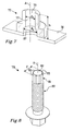
- Figures 7-9 illustrate a third embodiment of the attachment assembly according to the invention.
- Figure 7 illustrates the nut 73, which differs from those of the first and second embodiment in that there is no indentation in the bore 75.
- the retaining element is instead held by friction and resilient force in the main portion 77 of the bore 75 during attachment.
- the main portion 77 of the bore 75 has a cylindrical inner wall with a diameter d b .
- Figure 8 illustrates the screw 79 having a retaining element in the form of an end cap 81 fixedly attached to the screw 79 at an end 82 of the screw 79.
- the end cap 81 may be snap-fitted to the screw 79 and/or attached to it by means of an adhesive.
- the screw 79 and the retaining element 81 form an integral unit when being handled by the person performing the attachment.
- the shaft of the screw 79 is provided with a thread 83.
- the screw 79 has an outer diameter d o defined by the ridges of the thread 83 and an inner diameter d i defined by the grooves of the thread 83, the definitions being indicated in Figure 3 .
- the inner diameter is less than the outer diameter, d i ⁇ d o .
- the end cap 81 comprises a number of protrusions 85, in the illustrated embodiment four protrusions 85. They protrude in a radial direction and are adapted to ascertain a good contact between the retaining element 81 and the inner wall of the main portion 77 of the bore 75, when the screw 79 is pushed into the bore 75.
- the protrusions 85 also extend in the axial direction of the shaft of the screw.
- the end cap 81 is made of a resilient material, such as a polymer.
- the end cap 81 has a flat outer surface as seen along the axial direction of the shaft of the screw 79. Also the surface of the protrusions 85 is flat as seen along the axial direction. The flat surface of the end cap 81 extends longer than the axial distance between two adjacent threads 83, e.g. in the range of 1-5 millimetres. The end cap 81 has no flange or thread.
- An end portion 87 of the bore 75 to be located at the end of the bore 75 facing the first object 31 has a larger diameter d e than the diameter d b of the main portion 77 of the bore 75, which is located further away from the first object 31.
- Figure 9 illustrates the situation after the screw 79 has been pushed into the bore 75 by an axial force, such that the retaining element 81 contacts the main portion 77 of the bore 75.
- the screw 79 will enter also if the force deviates from the axial direction A, as long as it has a component in the axial direction A.
- the axial force used to push the screw 79 is not especially high; to push the screw 79 by hand force may for example be sufficient.
- the retaining element 81 will then keep the screw 79 in place relative to the nut 73 and hence to the first object, here the first portion 31.
- the screw 79 will not move outwards again by itself, since it is retained by the retaining element 81.
- the shape, the position and the resiliency of the retaining element 81 may be adapted to hold the screw 19. Moreover, the shape and the resiliency of the retaining element 81 may be adapted such that when the screw 19 is used to hold an object, for example an inflatable curtain arrangement 3, the retaining element 81 is strong enough to retain the screw 79 including the weight of the inflatable curtain arrangement 3. However, it is preferably possible to pull out the screw 79 again if applying a force above a predetermined level, e.g. if the inflatable curtain arrangement 3 is going to be exchanged. This predetermined level is selected to be high enough to ascertain that under normal conditions the retaining element 81 is strong enough to retain the screw 79 including the weight of the inflatable curtain arrangement 3.
- a predetermined level is selected to be high enough to ascertain that under normal conditions the retaining element 81 is strong enough to retain the screw 79 including the weight of the inflatable curtain arrangement 3.
- the screw 79 is held by friction between the protrusions 85 and the main portion 77 of the bore 75. Further, since a cross-sectional dimension c through two of the protrusions 85 and the axis of the screw 79 is larger than the diameter d b of the main portion 77 of the bore 75, see Figure 8 , the protrusions 85 will be somewhat deformed when the screw 79 is pushed into the bore 75. They then strive to go back to their original shape resulting in a resilient force contributing to holding the screw 79 in the intended place.
- This kind of retaining element 81 is appropriate for a bore 75 having a flat inner wall. There is no need for an indentation or any thread in the bore in order to retain the screw 79.
- the screw 79 In order to move the screw 79 further inwards into the bore 75, the screw 79 will be screwed, e.g. with a predefined torque. Since the object to be attached, i.e. the second object, in the example the inflatable curtain arrangement 3, is held in position at the object whereto it is to be attached, i.e. the first object, in this example the cantrail 7, by the screw 79 being retained by the retaining element 81 in the main portion 77 of the bore 75, the person making the attachment will have both hands free to attach the screw 79 to the nut 73.
- the screw 79 is preferably attached by a predefined torque which is selected to fulfil security and/or quality standards. Since the screw 79 is thread-cutting, it cuts its own thread in the main portion 77 of the bore 75 while being screwed into the bore 75.
- Figures 10-15 illustrate different variants of the retaining element.
- Figures 10a-c illustrate a ring-shaped member 23, as in the first embodiment of the attachment assembly 17 illustrated in Figures 3-5 .
- the ring-shaped member 23 is made of resilient material, such as rubber or plastic, which can change its shape. Thereby the outer diameter of the ring-shaped member 51 is less in the tensioned state than in the untensioned state.
- Figure 10b shows a cross-section of the ring-shaped member 23 in an untensioned state, i.e. having a normal shape, while Figure 10c shows the ring-shaped member 23 in a tensioned state, such as when pushing the screw 19 upwards into the bore 35, 47. The cross-section is then oval.
- the outer diameter of the ring-shaped member 23 is less in the tensioned state than in the untensioned state.
- the ring-shaped member 23 reaches the indentation 37, 45, it will spring back to its substantially normal shape, i.e. snapping into the indentation 37, 45, thereby retaining the screw 19.
- Figures 11 a and 11 b illustrate a second type of ring-shaped member 51.
- the ring-shaped member 51 has a slot 53.
- Figure 11 a shows the ring-shaped member 51 in an untensioned state, i.e. having a normal shape, wherein the slot 53 is open.
- Figure 11 b shows the ring-shaped member 51 in a tensioned state, such as when pushing the screw 19 upwards into the bore 35, 47, wherein the slot 53 is less wide than in the untensioned state or even closed. This is achieved by flexing the ring-shaped member 51 in the plane of the ring-shaped member 51 itself. Thereby the outer diameter of the ring-shaped member 51 is less in the tensioned state than in the untensioned state.
- the ring-shaped member 51 reaches the indentation 37, 45, it will spring back to its substantially normal shape, i.e. snapping into the indentation 37, 45, thereby retaining the screw 19.
- Figures 12a-c illustrate a third type of ring-shaped member 55.
- the ring-shaped member 55 comprises, or is constituted by, a brim 57, which is able to flex out of the plane of the ring-shaped member 55 itself.
- Figure 12b shows a cross-section of the ring-shaped member 55 in an untensioned state
- Figure 12c shows a cross-section of the ring-shaped member 55 in a tensioned state, such as when pushing the screw 19 upwards into the bore 35, 47, wherein the brim 57 is at least partly curved downwards.
- the outer diameter of the ring-shaped member 55 is less in the tensioned state than in the untensioned state.
- the brim 57 is more easily bent downwards, like in Figure 12c , than upwards.
- the ring-shaped member 55 reaches the indentation 37, 45, it will spring back to its substantially normal shape, e.g. snapping into the indentation 37, 45, thereby retaining the screw 19.
- the cross-section of Figure 12b is flat, it would also be possible that the brim 57 is angled downwards. This would help to obtain the desirable characteristics that the brim 57 is more easily bent downwards than upwards.
- Figures 13a-c illustrate a fourth type of ring-shaped member 59.
- the ring-shaped member 59 comprises a brim 61, which is divided into portions 61 a, 61 b, 61 c and 61 d, which are able to flex out of the plane of the ring-shaped member 55 itself.
- the number of portions may be one, two, three, four, or more.
- Figure 13b shows the ring-shaped member 59 in an untensioned state
- Figure 13c shows the ring-shaped member 59 in a tensioned state, such as when pushing the screw 19 upwards into the bore 35, 47, wherein the brim portions 61 a, 61 b, 61 c, and 61 d are curved downwards.
- the outer diameter of the ring-shaped member 59 is less in the tensioned state than in the untensioned state.
- the brim 61 is more easily bent downwards, as in Figure 13c , than upwards.
- Figures 14a and 14b illustrate a fifth type of ring-shaped member 63.
- the ring-shaped member 63 comprises a blind bore 65, which houses a snap member 67 and a spring member 69.
- the resiliency of the spring member 69 is chosen such that the snap member 67 is pushed outwards in a radial direction by the spring member 69 in an untensioned state. See Figure 14a.
- Figure 14b shows the ring-shaped member 63 in a tensioned state, such as when pushing the screw 19 upwards into the bore 35, 47, wherein the spring member 69 is compressed such that the snap member 67 is flush with the surface of the ring-shaped member 63.
- the outer diameter of the ring-shaped member 63 is less in the tensioned state than in the untensioned state.
- the snap member 67 will be pushed outwards by the spring member 69, hence snapping into the indentation 37, 45, thereby retaining the screw 19.
- One, two, three or more snap members may be provided.
- Figure 15 illustrates another kind of retaining element 71, which may have an arbitrary shape, regular or irregular, as is illustrated.
- the retaining element 71 is made of a thin film, e.g. made of plastic.
- the retaining element 71 may comprise, or be constituted by, a brim which may flex in a way already described in conjunction with Figures 12a-c .
- retaining elements illustrated in Figures 10-15 may also be held by friction to the inner wall of the bore and/or the resiliency may be used to hold them in the bore by a resilient force, e.g. when striving to go back to an original shape. If the retaining element is to be held by friction, it is preferred that the retaining element has a large enough surface area in contact with the inner wall of the bore to ascertain enough friction force. In such cases, the retaining element may extend in the axial direction of the shaft of the screw, e.g. in the range of 1-5 mm.
- a method for attaching a second object, such as the inflatable curtain arrangement 3, to a first object, such as the cantrail 7, by means of the attachment assembly 17 described herein comprises the steps of:
- the step a) may be performed beforehand, such that the first object is delivered with a fixedly attached nut, e.g. to an assembly plant for vehicles.
- the step b) may be performed beforehand.
- the screw 79 and the retaining element 81 may be handled as an integral unit.
- the attachment of the retaining element 81 to the screw may 79 in that case be performed in a separate manufacturing line delivering the integral unit of the screw 79 and the retaining element 81.
- the integral unit is pushed through the second object 3, through the first object 7 and into the bore 75 in one pushing operation in step d). It is then assumed that the second object 3 has been placed adjacent to the first object 7 in a position allowing the screw 79 to be screwed into the nut 73.
- the second object 3 may be delivered with the screw 19 attached to it, such that the head 25 of the screw 19 is located at one side of the second object 3 and the retaining element 23, 51, 55, 59, 63, 71 at an opposite side of the second object 3, the shaft 27 of the screw 19 going through the second aperture 39.
- the retaining element 23, 51, 55, 59, 63, 71 may be positioned on the screw 19 when performing the attachment.
- the retaining element 23 may be held in the indentation 37 of the nut 21 in step d), e.g. by a snap-fit function, as is described above, as would be possible for the ring-shaped member 23 of the first embodiment and for the different retaining elements described below in conjunction with Figures 7-12 .
- the retaining element may be held by friction to the inner wall and/or by a resilient force resulting from deforming a resilient retaining element.
- the first object may be a wall or a ceiling of a building.
- the first object may be a body portion of a vehicle, e.g. a cantrail or an A, B or C pillar.
- the second object is typically large and/or heavy, such that it is difficult to handle for one person. If in a building, the second object may be a panel, e.g. a wall panel or ceiling panel. If in a vehicle, the second object may be a panel or an inflatable curtain arrangement.
Landscapes
- Engineering & Computer Science (AREA)
- General Engineering & Computer Science (AREA)
- Mechanical Engineering (AREA)
- Dowels (AREA)
- Connection Of Plates (AREA)
Abstract
Description
- The present disclosure relates to an attachment assembly for attaching a second object to a first object. The disclosure further relates to a use of the attachment assembly for attaching an automotive part, such as an inflatable curtain arrangement, to a vehicle. In addition the disclosure relates to a unit for use in the attachment assembly, a first kit, a second kit, a vehicle, as well as to a method for attaching a second object to a first object.
- Attaching a second object to a first object may sometimes be difficult for one person, since there is a desire to simultaneously hold the second object at a suitable position for fastening to the first object, to hold a fastening member, such as a screw, and to hold a tool used for attaching the fastening member, such as a screw-driver. The difficulties are increased if the second object is large and/or heavy. It is also more difficult if there is limited space available for the person doing the work and/or the person is unable to see the position of the attachment.
- A typical situation may be when attaching an object, such as a panel, to a wall or a ceiling of a building, e.g. during construction. Another typical situation is during assembly of a vehicle when attaching an automotive part to the vehicle, e.g. when attaching an inflatable curtain arrangement to a cantrail, i.e. the portion of a vehicle body extending between the A, B and/or C pillars at the upper part of the vehicle. The inflatable curtain arrangement comprises a curtain-shaped airbag, which is adapted to cover the upper part of a vehicle's side in case of a side impact collision, thereby cushioning the heads of the passengers seated at that side. Since the inflatable curtain arrangement is part of a passenger protection system, it is desired that the fastening member is secured by a predetermined torque.
- Such attachment work may be carried out more easily by two persons, e.g. one person holding the second object in position and the other fastening it by means of the fastening member using the tool.
- Prior art solutions making it possible for one person to attach one object to another include using a temporary fixation of the second object to the first object, e.g. by means of a clamp to the first object or by a stand standing on e.g. the floor and pressing the second object towards the first object. Time is then spent to arrange the temporary fixation and to remove it afterwards.
- Document
US 6,851,710 B2 discloses using a clip, which is pushed into a corresponding opening of the vehicle surface thereby attaching an inflatable curtain arrangement to a vehicle. One embodiment discloses that a clip is used in combination with a rigid mechanical fastener, illustrated as a bolt. - In some situations, a clip does not provide enough mechanical strength of the final attachment. In the solution of
US 6,851,710 B2 comprising the combined use of the clip and the rigid mechanical fastener, two different attachment steps are carried out by the operator, which takes some extra time. - There is thus a desire for an improved attachment system, in particular for attaching an inflatable curtain arrangement to a vehicle, which attachment system is suitable for being handled by one person.
- The object of the present disclosure is to overcome or ameliorate at least one of the disadvantages of the prior art, or to provide a useful alternative.
- It is desirable to provide an attachment assembly, which offers a less complicated and easier to use attachment than the prior art.
- It is further desirable that one person can carry out the attachment alone.
- An object above may be achieved by the subject-matter of claim 1.
- Thus, in a first aspect of the present invention there is provided an attachment assembly for attaching a second object to a first object. The attachment assembly comprises a screw and a nut. The screw has a head and a shaft and at least a portion of the shaft comprises a thread. The nut is adapted to be fixedly attached to the first object. The nut comprises a bore adapted for receiving the screw. The bore has an axial direction and a height along the axial direction. The attachment assembly further comprises a retaining element, which is adapted to be positioned at a perimeter of the shaft of the screw. The bore comprises an inner wall, at least a portion of the inner wall being adapted for receiving and holding the retaining element at least in the axial direction. The bore is unthreaded and the screw is a thread-cutting screw or a thread-forming screw, which is adapted to cooperate with the bore.
- The first object may be a wall or a ceiling of a building. Alternatively, the first object may be a body portion of a vehicle, e.g. a cantrail or an A, B or C pillar.
- The second object is typically large and/or heavy, such that it is difficult to handle for one person. If in a building, the second object may be a panel, e.g. a wall panel or ceiling panel. If in a vehicle, the second object may be a panel or an inflatable curtain arrangement.
- The bore may be a through-going axial bore or it may be a blind bore. The at least a portion of the inner wall of the bore may have an inner diameter which is less than the outer thread diameter of the screw.
- The screw is intended to be screwed into the nut, which is fixedly attached to the first object to thereby attach the second object to the first object. As used herein, a screw is a fastener capable of being inserted into holes in assembled parts, forming its own thread, and of being tightened or released by torqueing a head of the screw.
- The nut may be fixedly attached to a first substantially plate-shaped portion of the first object, which first portion comprises a first aperture. The nut is fixedly attached or attachable to the first portion e.g. by welding or adhesively, such that the nut is aligned with the first aperture, i.e. the bore of the nut is aligned with the first aperture, such that a screw going through the first aperture also can go through the bore. If welded, the nut may constitute a weld nut. The first aperture may be circular, polygonal or have an arbitrary shape. It should be large enough to allow the shaft of screw to pass. Yet, the nut should remain on the upper side of the first portion.
- Since the retaining element is positioned on the screw, the user of the attachment assembly can easily ascertain that the retaining element is present, e.g. by looking at the screw or by touching it. This is in comparison to prior art attachment assemblies, wherein a retaining element is instead located in the nut, e.g. inside the bore, which is more difficult to see and/or touch.
- The screw and the nut are manufactured separately from each other. They may also be sold and/or used as separate units, being prepared for later attachment to each other. Purely as an example, the nut may be delivered as a part of a first kit also comprising the first object, e.g. a cantrail being sent to an assembly plant for vehicles, wherein another automotive part, such as an inflatable curtain arrangement, is attached to the cantrail. The screw may be delivered as a separate unit or may be delivered as part of a second kit also comprising the automotive part. The retaining element may be delivered mounted to the screw or it may be delivered as a separate unit to be mounted to the screw at the assembly plant.
- Preferably the second object, e.g. a second substantially plate-shaped portion of it, is provided with a second aperture having a large enough diameter and/or shape for the shaft of the screw to pass. The second aperture may be circular, polygonal or have an arbitrary shape. The head of the screw has a larger diameter than the shaft, such that the screw is able to retain the second object in place by means of the head. Alternatively, or as a complement, a washer may be used adjacent to the head of the screw for retaining the second object.
- The screw is adapted to be pushed into the bore of the nut as far enough for the retaining element to be retained by the portion of the inner wall of the bore, wherein the retaining element is retained in such a way that it can retain the screw, and optionally the second object. The attachment assembly may be configured such that the retaining element can carry the weight of the screw. As an alternative, or as a complement, the attachment assembly may be configured such that the retaining element can carry the weight of the second object and the screw. The attachment may be performed when the second object is in a hanging position. Purely as an example, the shape, the size, the material, the resiliency and/or the position of the retaining element may be selected in order to achieve the desired weight-carrying capacity. However, it is preferably possible to pull out the screw again if applying a force above a predetermined level, e.g. if the second object is going to be exchanged. This predetermined level is selected to be high enough to ascertain that under normal conditions the retaining element is strong enough to retain the screw including the weight of the second object.
- The nut may comprise an indentation adapted for receiving and holding the retaining element at least in the axial direction, the indentation forming a portion of the inner wall of the bore. There is then provided an attachment assembly for attaching a second object to a first object. The attachment assembly comprises a screw and a nut. The screw has a head and a shaft and at least a portion of the shaft comprises a thread. The nut is adapted to be fixedly attached to the first object. The nut comprises a bore adapted for receiving the screw. The bore has an axial direction and a height along the axial direction. The attachment assembly further comprises a retaining element, which is adapted to be positioned at a perimeter of the shaft of the screw. The nut comprises an indentation adapted for receiving and holding the retaining element at least in the axial direction.
- If the nut comprises an indentation, the screw is adapted to be pushed into the bore of the nut as far enough for the retaining element to reach the indentation, wherein the retaining element is received in such a way that the indentation can retain the screw, and optionally the second object. Preferably, a snap-in function is obtained by the shape and/or resiliency of the retaining element in relation to the indentation. The indentation may have a shape corresponding to the shape of the retaining element. Further, the screw is retained by the nut, once the screw has reached a pre-defined position in relation to the nut and hence also in relation to the first object. The pre-defined position is determined by the location of the indentation in the nut and the relative position of the retaining element on the screw. This differs from some prior art attachment assemblies, wherein the screw indeed is retained by the nut, but wherein there is no predefined relative position between the screw and the nut when retained.
- Moreover, by utilizing the above-mentioned snap-in function into the indentation the person pushing the screw into the nut can easily determine that the retaining element has reached the intended position in the indentation without having to see the attachment assembly itself, e.g. by sensing that the retaining element has reached its proper retaining position and/or by an audible "click" being heard.
- The indentation may be located at a perimeter of the bore of the nut. It may be manufactured in the same manufacturing step as the bore.
- The indentation may be located at a first end of the bore, which end is adapted to face the first object. Then the retaining element may be received in a space defined by the indentation and the first object together.
- As an alternative, or as a complement, the indentation may be located within the bore, such that a distance x between the first end of the bore facing the first object and the indentation fulfils 0 < x ≤ h, preferably such that 0.1h ≤ x ≤ h. Thereby the space for receiving and retaining the retaining element is independent of the diameter and the shape of the first aperture.
- As an alternative to the above-described indentation comprised in the bore to receive and hold the retaining element, a main portion of the bore may comprise a substantially flat inner wall having a cylindrical shape. The retaining element may then be held by friction to the inner wall and/or by a resilient force resulting from deforming a resilient retaining element. The main portion of the bore is the portion intended to cooperate with the screw.
- An end portion of the bore located at the end of the bore facing the first object may have a wider cross-section than the main portion of the bore, which is located further away from the first object. Thereby a possible misalignment between the shaft of the screw and the axial direction of the bore may be compensated for, since the screw may be entered into the bore at a somewhat oblique angle.
- The retaining element may be adapted to be positioned in a thread on the shaft of the screw. This will help to hold the retaining element in place on the screw. As an alternative, or as a complement, the retaining element may be held by friction to the shaft of the screw, or it may be adhered to the screw by an adhesive. As yet an alternative, the shaft may be provided with a groove, particularly adapted to hold the retaining element.
- The retaining element may be adapted to be fixedly attached to the shaft of the screw, e.g. adhered to the screw by an adhesive or a snap-in function.
- The retaining element may be adapted to be located at or adjacent to an end of the shaft of the screw. However, the retaining element is anyway positioned at the perimeter of the shaft of the screw, such that the retaining element forms part of the perimeter. The end of the screw is at the end of the shaft, which end is opposite to the head. The end is hence furthest away from the head.
- The retaining element may comprise, or be constituted by, a ring-shaped member, e.g. a ring with a closed perimeter or a slotted ring, the ring-shaped member having an inner diameter being adapted to cooperate with the shaft of the screw. The ring-shaped member preferably has a circular cross-section. The inner diameter of the ring-shaped member may be less than an outer thread diameter of the screw and larger than an inner thread diameter of the screw, such that the retaining element may be held in a thread on the screw.
- The retaining element may be resilient, e.g. having a resilient shape and/or comprising a resilient member. The retaining element may be resilient in the plane of the retaining element, e.g. by being able to change its diameter. The retaining element may be compressible in the radial direction. As an alternative, or as a complement, the retaining element may be able to flex out of its plane, e.g. in the axial direction. The retaining element may be bendable or foldable in the axial direction. Thereby the effective outer diameter is changed. The whole retaining element may be resilient or one or more portions of it may be resilient.
- The retaining element may be adapted to be held by friction and/or by a resilient force to to the at least a portion of the inner wall of the bore. The resilient force may result from deforming a resilient retaining element. The retaining element may have a somewhat larger diameter than at least the main portion of the bore.
- The retaining element may be an end cap attached to the screw. The end cap may be snap-fitted to the screw and/or attached to it by means of an adhesive. The screw and the retaining element thus form an integral unit when being handled by the person, performing the attachment. The maximum cross-sectional dimension of the end cap may be chosen to be less than the outer thread diameter of the screw but larger than the inner thread diameter of the screw.
- The end cap may comprise at least one protrusion, e.g. one, two, three, four, six or eight, which protrude in a radial direction and ascertain a good contact between the retaining element and the inner wall of the bore. The protrusion may also extend in the axial direction of the shaft of the screw. Purely as an example, the protrusion may extend longer in the axial direction of the shaft than a corresponding axial distance between two adjacent threads. The protrusion may e.g. extend in the range of 1-5 millimetres. The end cap, including any protrusions, may be made of an at least somewhat resilient material, such as a polymer. The end cap may have a flat outer surface as seen along the axial direction, i.e. it does not comprise any flange, nor any thread. The protrusion may have a major extension in the axial direction of the screw.
- During attachment, the screw may be held by friction between the protrusions and the main portion of the bore. If a cross-sectional dimension through at least one of the protrusions and the axis of the screw is larger than the diameter of the main portion of the bore, the protrusions will be deformed when pushing the screw into the bore. The protrusions then strive to go back to their original shape resulting in a resilient force contributing to holding the screw in the intended place. This kind of retaining element is appropriate for a bore having a flat inner wall. There is no need for an indentation or any thread in the bore in order to retain the screw. There may also be a resilient force resulting from the retaining element itself having a larger diameter than the diameter of the main portion of the bore. In that case the protrusions may be dispensed with. The retaining element may then be deformed also in an axial direction.
- As mentioned above, the screw is a thread-cutting screw or a thread-forming screw. At least a portion of the bore may in that case have an inner diameter which is less than the outer thread diameter of the screw. A thread-cutting screw or thread-forming screw provides a higher friction than a corresponding non-thread-cutting screw or non-thread-forming screw, thereby increasing the mechanical strength of the attachment. It is thus possible to use a screw of smaller dimensions, e.g. by going down one step in the ISO metric M series of screw dimensions. In addition, using a thread-cutting screw or a thread-forming screw reduces the risk that the attachment assembly is destroyed due to improper alignment of the threads of the screw and the bore, respectively. There will thus be a higher tolerance for tightening the screw with a slightly oblique angle. Further, by using an unthreaded bore and a thread-cutting screw or thread-forming screw, the risk of a defect thread and/or of a thread blocked by debris is avoided, since the thread is cut or formed when they are to be used.
- A suitable material for the screw is steel. A suitable material for the nut is steel. The material characteristics of the nut are selected such that the screw is able to cut or form a thread in the nut.
- In a second aspect of the present invention there is provided a use of an attachment assembly as described herein for attaching an automotive part to a vehicle, wherein the first object is a body portion of the vehicle, e.g. a cantrail, and the second object is an automotive part, e.g. an inflatable curtain arrangement.
- In a third aspect of the present invention there is provided a unit for use in the attachment assembly described herein. The unit comprises a thread-cutting screw, which comprises a head and a shaft, at least a portion of the shaft comprising a thread, and a retaining element positioned at a perimeter of the shaft of the screw. The retaining element is fixedly attached to the screw at or adjacent to an end of the shaft of the screw. The retaining element comprises a flat outer surface as seen along the axial direction of the screw. The retaining element may further comprise at least one protrusion as described herein.
- In a fourth aspect of the present invention there is provided a first kit comprising a cantrail for a vehicle and the nut of the attachment assembly as described herein. The cantrail comprises a first substantially plate-shaped portion, which comprises a first aperture. The nut is fixedly attached to the first portion aligned with the first aperture. The nut may be attached by welding, thus constituting a weld nut. The first aperture may be circular, polygonal or have an arbitrary shape. The nut may comprise the above-mentioned indentation.
- In a fifth aspect of the present invention there is provided a second kit comprising an inflatable curtain arrangement for a vehicle, the screw of the attachment assembly as described herein and the retaining element of the attachment assembly as described herein. The retaining element is positioned at the screw. The inflatable curtain arrangement comprises a second substantially plate-shaped portion comprising a second aperture. The second aperture may be circular, polygonal or have an arbitrary shape. The shaft of the screw goes through the second aperture, such that the head of the screw is located at one side of the second portion and the retaining element at an opposite side of the second portion. The second aperture has a shape/diameter which is larger than that of an inner diameter of the shaft of the screw and less than an outer shape/diameter of the retaining element and less than an outer shape/diameter of the head of the screw.
- In a sixth aspect of the present invention there is provided a vehicle comprising an attachment assembly as described herein, the unit for use in the attachment assembly, a first kit as described herein and/or a second kit as described herein.
- In a seventh aspect of the present invention there is provided a method for attaching a second object to a first object by means of an attachment assembly as described herein. The first object comprises a first substantially plate-shaped portion comprising a first aperture. The second object comprises a second substantially plate-shaped portion comprising a second aperture. The attachment assembly comprises a screw having a head and a shaft, at least a portion of the shaft comprising a thread, a nut comprising a bore adapted for receiving the screw, the bore having an axial direction, and a retaining element adapted to be positioned at a perimeter of the shaft of the screw. The bore comprises an inner wall, at least a portion of the inner wall being adapted for receiving and holding the retaining element at least in the axial direction. The method comprises the steps of:
- a) Attaching the nut to the first portion of the first object, such that the bore is aligned with the first aperture.
- b) Positioning the retaining element at the screw.
- c) Placing the second object adjacent to the first object in a position allowing the screw to be screwed into the nut.
- d) Applying a force in the axial direction to the screw, thereby pushing the retaining element through the first aperture and into the bore of the nut, such that the retaining element is received and held at least in the axial direction.
- e) Letting the retaining element retain the screw, and optionally the second object, while screwing the screw into the nut, wherein the screw cuts or forms its thread at the inner wall of the bore during screwing, thereby attaching the second object to the first object.
- The step a) may be performed beforehand, such that the first object is delivered with a fixedly attached nut, e.g. to an assembly plant for vehicles.
- The step b) may be performed beforehand.
- If using the above-mentioned retaining element, which is fixedly attached to the shaft of the screw, the screw and the retaining element may be handled as an integral unit. The attachment of the retaining element to the screw may in that case be performed in a separate manufacturing line delivering the integral unit of the screw and the retaining element. Then the integral unit is pushed through the second object, through the first object and into the bore in one pushing operation in step d). It is then assumed that the second object has been placed adjacent to the first object in a position allowing the screw to be screwed into the nut.
- If using a retaining element which is not fixedly attached to the shaft of the screw, the second object may be delivered with the screw attached to it, such that the head of the screw is located at one side of the second object and the retaining element at an opposite side of the second object, the shaft of the screw going through the second aperture. As an alternative the retaining element may be positioned on the screw when performing the attachment.
- The retaining element may be held in an indentation as described above, e.g. by a snap-fit function, as is described above. See step d). As an alternative or a complement, the retaining element may be held by friction to the inner wall of the bore and/or by a resilient force resulting from deforming a resilient retaining element, as is also described above.
- The first object may be a body portion of a vehicle, such as a cantrail, and the second object may be an inflatable curtain arrangement.
- The present invention will hereinafter be further explained by means of non-limiting examples with reference to the appended drawings wherein:
-
Fig. 1 is a schematic side view of a portion of a vehicle comprising an inflatable curtain arrangement, -
Fig. 2 illustrates the inflatable curtain arrangement in a storage state, -
Fig. 3 illustrates a first embodiment of an attachment assembly according to the invention, -
Fig. 4 is a schematic cross-sectional view of a nut of the attachment assembly ofFig. 3 , -
Fig. 5a and b illustrate the attachment assembly ofFig. 3 in use, -
Fig. 6 is a schematic cross-sectional view of a nut of a second embodiment of the attachment assembly, -
Fig. 7 is a schematic cross-sectional view of a nut of a third embodiment of the attachment assembly, -
Fig. 8 is a schematic view of a unit comprising a screw and a retaining element of the third embodiment, -
Fig. 9 is a schematic view of the attachment assembly of the third embodiment in use, -
Fig. 10a-c illustrate a retaining element in an untensioned state and in a tensioned state, -
Fig. 11a-b illustrate an alternative retaining element in a untensioned state and in a tensioned state, -
Fig. 12a-c illustrate a second alternative retaining element in an untensioned state and in a tensioned state, -
Fig. 13a-c illustrate a third alternative retaining element in an untensioned state and in a tensioned state, -
Fig. 14a-b illustrate a fourth alternative retaining element in an untensioned state and in a tensioned state, and -
Fig. 15 illustrates a fifth alternative retaining element. - It should be noted that the appended drawings are not necessarily drawn to scale and that the dimensions of some features of the present invention may have been exaggerated for the sake of clarity.
- The invention will, in the following, be exemplified by embodiments. It should however be realized that the embodiments are included in order to explain principles of the invention and not to limit the scope of the invention, defined by the appended claims. Details from two or more of the embodiments may be combined with each other.
-
Figure 1 schematically illustrates a side view of a portion of a vehicle 1 comprising aninflatable curtain arrangement 3. Theinflatable curtain arrangement 3 is shown in its deployed state, wherein aninflatable curtain 5 is ready to protect a passenger at a side impact on the vehicle 1. Theinflatable curtain arrangement 3 is attached to a body of the vehicle 1, e.g. to a cantrail 7. - Normally the
inflatable curtain arrangement 3 is in a storage state, seeFigure 2 , wherein it is folded and or rolled to a tubular shape. Aninflator 9 is connected to the inflatable curtain arrangement. Theinflator 9 may be activated by crash sensors, in case a collision occurs, thereby inflating theinflatable curtain arrangement 3, such that it assumes the deployed state as illustrated byFigure 1 . - The
inflatable curtain arrangement 3 is attached to the cantrail 7 by means ofbrackets 11 comprised in theinflatable curtain arrangement 3. Thebrackets 11 are used to retain theinflatable curtain arrangement 3 to the cantrail 7. In the illustrated embodiment, aportion 13 of thebracket 11 at least partly encircles atubular body 15 of theinflatable curtain arrangement 3. The encirclingportion 13 may be resilient and comprise a slot (not illustrated). When the encirclingportion 13 is to be connected to thetubular body 15, the slot may in that case be widened such that thetubular body 15 can be entered through the slot and then the encirclingportion 13 springs back to a retaining position, as the one illustrated inFigure 2 . Alternatively, the bracket may be clipped to or around thetubular body 15, or the bracket may be glued or welded to theinflatable curtain arrangement 3. -
Figures 3-5 illustrate anattachment assembly 17 according to a first embodiment of the invention. Theattachment assembly 17 of the first embodiment comprises ascrew 19, anut 21 and a retainingelement 23. - The
screw 19 comprises ahead 25 and ashaft 27. At least a portion of theshaft 27, preferably a major portion of theshaft 27, is provided with athread 29 following the surface of theshaft 27. Thescrew 19 has an outer diameter do defined by the ridges of thethread 29 and an inner diameter di defined by the grooves of thethread 29. By definition the inner diameter is less than the outer diameter, di < do. - The retaining
element 23 is adapted to be positioned at a perimeter of theshaft 27 of thescrew 19. In the illustrated example the retainingelement 23 is constituted by a ring-shaped member made of resilient material, such as rubber or plastic. The ring-shapedmember 23 is further described in conjunction withFigure 10 . Other examples of retaining elements are described in conjunction withFigures 11-15 . The ring-shapedmember 23 may substantially located in thethread 29, such that thethread 29 can help to keep the ring-shapedmember 23 at the screw, thereby preventing it from falling off and/or getting lost. As an alternative, or as a complement, the ring-shapedmember 23 may be held by friction to theshaft 27 of thescrew 19, or the ring-shapedmember 23 may be adhered to thescrew 19 by an adhesive. - The
nut 21 is fixedly attached to a first substantially plate-shapedportion 31 of a first object, e.g. of the cantrail 7 ofFigure 1 , whichfirst portion 31 comprises afirst aperture 33. Thenut 21 is fixedly attached to thefirst portion 31 e.g. by welding, such that thenut 21 is aligned with thefirst aperture 33, thenut 21 then constituting a weld nut. Thefirst aperture 33 may be circular, as is illustrated, polygonal or have an arbitrary shape. It should be large enough to allow theshaft 27 ofscrew 19 to pass. Yet, thenut 21 should remain on the upper side of thefirst portion 31. -
Figure 4 shows a cross-section of thenut 21. Thenut 21 comprises abore 35 adapted for receiving thescrew 19. Thebore 35 has an axial direction A, a height h along the axial direction and it comprises a main portion having a diameter db. In the illustrated embodiment, thebore 35 goes all the way through thenut 21, but it may also be a blind bore. Thenut 21 further comprises anindentation 37 adapted for receiving and holding the retainingelement 23 at least in the axial direction A. Theindentation 37 may allow rotational movement of the retainingelement 23 around the axial direction A. In the illustrated embodiment a space is defined by theindentation 37 and the upper surface of thefirst portion 31 in a region around thefirst aperture 33, which space is adapted for receiving and retaining the retainingelement 23. - Going back again to
Figure 3 , it may be gleaned that thescrew 19 is located such that theshaft 27 goes through asecond aperture 39 in a second substantially plate-shapedportion 41 of a second object, e.g. thebracket 11 forming a part of aninflatable curtain arrangement 3 as shown inFigure 2 . Thesecond aperture 39 has a diameter, which is large enough for theshaft 27 of thescrew 19 to go through, but which is small enough for thehead 25 of thescrew 19 to be stopped, such that thehead 25 will be able to retain theinflatable curtain arrangement 3, once thescrew 19 has been attached to the body of the vehicle, e.g. the cantrail 7. Thesecond aperture 39 may be circular, polygonal or have an arbitrary shape. Thehead 25 of thescrew 19 has a larger diameter than the rest of thescrew 19. Optionally a washer may be used to further increase the diameter of the head. Thehead 25 is located below thesecond portion 41 and the retainingelement 23 is located above thesecond portion 41. The outer shape of the retainingelement 23 is larger than that ofsecond aperture 39, such that the retainingelement 23 will hold the screw in place in the second object, e.g. thebracket 11. This helps to retain thescrew 19 in theinflatable curtain arrangement 3, thereby avoiding, or at least reducing, the risk of dropping thescrew 19. - The
screw 19 is thread-forming or thread-cutting, and thenut 21 unthreaded, such that thescrew 19 can form or cut a thread on its way through thebore 35. -
Figure 5a illustrates the situation after thescrew 19 has been pushed into thenut 21 by an axial force. Thescrew 19 will enter also if the force deviates from the axial direction A, as long as it has a component in the axial direction A. The axial force used to push thescrew 19 is not especially high; to push thescrew 19 by hand force is for example sufficient. As thescrew 19 is being pushed inwards through thefirst aperture 33 and into thenut 21, the retainingelement 23 is pushed until it reaches theindentation 37, it then expands and fills theindentation 37, achieving a snap-in function, such that the person pushing thescrew 19 can determine that the retainingelement 23 has reached the intended position in theindentation 37 and thescrew 19 thus has reached a pre-defined position in relation to thenut 21, and hence to the first object, without having to see theattachment assembly 17 itself, e.g. by sensing that the retainingelement 23 has reached its proper retaining position and/or by an audible "click" being heard. - The retaining
element 23 will keep thescrew 19 in place relative to thenut 21 and hence to the first object, here thefirst portion 31. Thescrew 19 will not move outwards again by itself, since it is retained by the retainingelement 23. - The shape and the resiliency of the retaining
element 23 may be adapted to hold thescrew 19. Moreover, the shape and the resiliency of the retainingelement 23 may be adapted such that when thescrew 19 is used to hold an object, for example aninflatable curtain arrangement 3, the retainingelement 23 is strong enough to retain thescrew 19 including the weight of theinflatable curtain arrangement 3. However, it is preferably anyway possible to pull out thescrew 19 again if applying a force above a predetermined level, e.g. if theinflatable curtain arrangement 3 is going to be exchanged. This predetermined level is selected to be high enough to ascertain that under normal conditions the retainingelement 23 is strong enough to retain thescrew 19 including the weight of theinflatable curtain arrangement 3. - In order to move the
screw 19 further inwards into thebore 35, thescrew 19 will be screwed, e.g. with a predefined torque. SeeFigure 5b . Since the object to be attached, i.e. the second object, in the example theinflatable curtain arrangement 3, is held in position at the object whereto it is to be attached, i.e. the first object, in this example the cantrail 7, by thescrew 19 being retained by the retainingelement 23 in theindentation 37, the person making the attachment will have both hands free to attach thescrew 19 to thenut 21. Thescrew 19 is preferably attached by a predefined torque which is selected to fulfil security and/or quality standards. In the illustrated embodiment, thescrew 19 is thread-forming, i.e. thescrew 19 forms its own thread while being screwed into thebore 35. - The above-described
attachment assembly 17 may be handled also for the case when the person making the attachment cannot see theattachment assembly 17 during assembly. -
Figure 6 is a schematic cross-sectional view of anut 43 of a second embodiment of the attachment assembly according to the invention. Thenut 43 of the second embodiment differs from thenut 21 of the first embodiment in that anindentation 45 is formed entirely in thenut 43 itself. Thenut 43 comprises abore 47 adapted for receiving thescrew 19. Thebore 47 has an axial direction A and a height h along the axial direction. Theindentation 45 is adapted to hold the retainingelement 23 at least in the axial direction A, but may allow rotational movement of the retainingelement 23 around the axial direction A. In the illustrated embodiment, thebore 47 goes all the way through thenut 43, but it may also be a blind bore. Theindentation 45 is located at a distance x from afirst end 49 ofbore 47 facing the first object, here thefirst portion 31, wherein x fulfils 0 < x ≤ h, preferably such that 0.1h ≤ x ≤ h, h being the height along the axial direction A. -
Figures 7-9 illustrate a third embodiment of the attachment assembly according to the invention.Figure 7 illustrates thenut 73, which differs from those of the first and second embodiment in that there is no indentation in thebore 75. Instead, as will be further described below, the retaining element is instead held by friction and resilient force in themain portion 77 of thebore 75 during attachment. Themain portion 77 of thebore 75 has a cylindrical inner wall with a diameter db. -
Figure 8 illustrates thescrew 79 having a retaining element in the form of anend cap 81 fixedly attached to thescrew 79 at anend 82 of thescrew 79. Theend cap 81 may be snap-fitted to thescrew 79 and/or attached to it by means of an adhesive. Thescrew 79 and the retainingelement 81 form an integral unit when being handled by the person performing the attachment. The shaft of thescrew 79 is provided with athread 83. Thescrew 79 has an outer diameter do defined by the ridges of thethread 83 and an inner diameter di defined by the grooves of thethread 83, the definitions being indicated inFigure 3 . By definition the inner diameter is less than the outer diameter, di < do. - The
end cap 81 comprises a number ofprotrusions 85, in the illustrated embodiment fourprotrusions 85. They protrude in a radial direction and are adapted to ascertain a good contact between the retainingelement 81 and the inner wall of themain portion 77 of thebore 75, when thescrew 79 is pushed into thebore 75. Theprotrusions 85 also extend in the axial direction of the shaft of the screw. Theend cap 81 is made of a resilient material, such as a polymer. - The
end cap 81 has a flat outer surface as seen along the axial direction of the shaft of thescrew 79. Also the surface of theprotrusions 85 is flat as seen along the axial direction. The flat surface of theend cap 81 extends longer than the axial distance between twoadjacent threads 83, e.g. in the range of 1-5 millimetres. Theend cap 81 has no flange or thread. - An
end portion 87 of thebore 75 to be located at the end of thebore 75 facing thefirst object 31 has a larger diameter de than the diameter db of themain portion 77 of thebore 75, which is located further away from thefirst object 31. Thereby a possible misalignment between the shaft of thescrew 79 and the axial direction A of thebore 75 may be compensated for, since thescrew 79 may be entered into thebore 75 at a somewhat oblique angle. This kind of wider end portion may also be seen in the first and second embodiments illustrated inFigure 4 andFigure 6 . -
Figure 9 illustrates the situation after thescrew 79 has been pushed into thebore 75 by an axial force, such that the retainingelement 81 contacts themain portion 77 of thebore 75. Thescrew 79 will enter also if the force deviates from the axial direction A, as long as it has a component in the axial direction A. The axial force used to push thescrew 79 is not especially high; to push thescrew 79 by hand force may for example be sufficient. - The retaining
element 81 will then keep thescrew 79 in place relative to thenut 73 and hence to the first object, here thefirst portion 31. Thescrew 79 will not move outwards again by itself, since it is retained by the retainingelement 81. - The shape, the position and the resiliency of the retaining
element 81 may be adapted to hold thescrew 19. Moreover, the shape and the resiliency of the retainingelement 81 may be adapted such that when thescrew 19 is used to hold an object, for example aninflatable curtain arrangement 3, the retainingelement 81 is strong enough to retain thescrew 79 including the weight of theinflatable curtain arrangement 3. However, it is preferably possible to pull out thescrew 79 again if applying a force above a predetermined level, e.g. if theinflatable curtain arrangement 3 is going to be exchanged. This predetermined level is selected to be high enough to ascertain that under normal conditions the retainingelement 81 is strong enough to retain thescrew 79 including the weight of theinflatable curtain arrangement 3. - In the illustrated third embodiment, the
screw 79 is held by friction between theprotrusions 85 and themain portion 77 of thebore 75. Further, since a cross-sectional dimension c through two of theprotrusions 85 and the axis of thescrew 79 is larger than the diameter db of themain portion 77 of thebore 75, seeFigure 8 , theprotrusions 85 will be somewhat deformed when thescrew 79 is pushed into thebore 75. They then strive to go back to their original shape resulting in a resilient force contributing to holding thescrew 79 in the intended place. This kind of retainingelement 81 is appropriate for abore 75 having a flat inner wall. There is no need for an indentation or any thread in the bore in order to retain thescrew 79. - In order to move the
screw 79 further inwards into thebore 75, thescrew 79 will be screwed, e.g. with a predefined torque. Since the object to be attached, i.e. the second object, in the example theinflatable curtain arrangement 3, is held in position at the object whereto it is to be attached, i.e. the first object, in this example the cantrail 7, by thescrew 79 being retained by the retainingelement 81 in themain portion 77 of thebore 75, the person making the attachment will have both hands free to attach thescrew 79 to thenut 73. Thescrew 79 is preferably attached by a predefined torque which is selected to fulfil security and/or quality standards. Since thescrew 79 is thread-cutting, it cuts its own thread in themain portion 77 of thebore 75 while being screwed into thebore 75. -
Figures 10-15 illustrate different variants of the retaining element. -
Figures 10a-c illustrate a ring-shapedmember 23, as in the first embodiment of theattachment assembly 17 illustrated inFigures 3-5 . The ring-shapedmember 23 is made of resilient material, such as rubber or plastic, which can change its shape. Thereby the outer diameter of the ring-shapedmember 51 is less in the tensioned state than in the untensioned state.Figure 10b shows a cross-section of the ring-shapedmember 23 in an untensioned state, i.e. having a normal shape, whileFigure 10c shows the ring-shapedmember 23 in a tensioned state, such as when pushing thescrew 19 upwards into thebore member 23 is less in the tensioned state than in the untensioned state. When the ring-shapedmember 23 reaches theindentation indentation screw 19. -
Figures 11 a and 11 b illustrate a second type of ring-shapedmember 51. The ring-shapedmember 51 has aslot 53.Figure 11 a shows the ring-shapedmember 51 in an untensioned state, i.e. having a normal shape, wherein theslot 53 is open.Figure 11 b shows the ring-shapedmember 51 in a tensioned state, such as when pushing thescrew 19 upwards into thebore slot 53 is less wide than in the untensioned state or even closed. This is achieved by flexing the ring-shapedmember 51 in the plane of the ring-shapedmember 51 itself. Thereby the outer diameter of the ring-shapedmember 51 is less in the tensioned state than in the untensioned state. When the ring-shapedmember 51 reaches theindentation indentation screw 19. -
Figures 12a-c illustrate a third type of ring-shapedmember 55. The ring-shapedmember 55 comprises, or is constituted by, abrim 57, which is able to flex out of the plane of the ring-shapedmember 55 itself.Figure 12b shows a cross-section of the ring-shapedmember 55 in an untensioned state, whileFigure 12c shows a cross-section of the ring-shapedmember 55 in a tensioned state, such as when pushing thescrew 19 upwards into thebore brim 57 is at least partly curved downwards. Thereby the outer diameter of the ring-shapedmember 55 is less in the tensioned state than in the untensioned state. Preferably thebrim 57 is more easily bent downwards, like inFigure 12c , than upwards. When the ring-shapedmember 55 reaches theindentation indentation screw 19. Although the cross-section ofFigure 12b is flat, it would also be possible that thebrim 57 is angled downwards. This would help to obtain the desirable characteristics that thebrim 57 is more easily bent downwards than upwards. -
Figures 13a-c illustrate a fourth type of ring-shapedmember 59. The ring-shapedmember 59 comprises abrim 61, which is divided intoportions member 55 itself. The number of portions may be one, two, three, four, or more.Figure 13b shows the ring-shapedmember 59 in an untensioned state, whileFigure 13c shows the ring-shapedmember 59 in a tensioned state, such as when pushing thescrew 19 upwards into thebore brim portions member 59 is less in the tensioned state than in the untensioned state. Preferably thebrim 61 is more easily bent downwards, as inFigure 13c , than upwards. - When the ring-shaped
member 59 reaches theindentation indentation screw 19. Although the cross-section ofFigure 13b is flat, it would also be possible that thebrim 61 is angled downwards. This would help to obtain the desirable characteristics that thebrim 61 is more easily bent downwards than upwards. -
Figures 14a and 14b illustrate a fifth type of ring-shapedmember 63. The ring-shapedmember 63 comprises ablind bore 65, which houses asnap member 67 and aspring member 69. The resiliency of thespring member 69 is chosen such that thesnap member 67 is pushed outwards in a radial direction by thespring member 69 in an untensioned state. SeeFigure 14a. Figure 14b shows the ring-shapedmember 63 in a tensioned state, such as when pushing thescrew 19 upwards into thebore spring member 69 is compressed such that thesnap member 67 is flush with the surface of the ring-shapedmember 63. Thereby the outer diameter of the ring-shapedmember 63 is less in the tensioned state than in the untensioned state. When the ring-shapedmember 59 reaches theindentation snap member 67 will be pushed outwards by thespring member 69, hence snapping into theindentation screw 19. One, two, three or more snap members may be provided. -
Figure 15 illustrates another kind of retainingelement 71, which may have an arbitrary shape, regular or irregular, as is illustrated. The retainingelement 71 is made of a thin film, e.g. made of plastic. The retainingelement 71 may comprise, or be constituted by, a brim which may flex in a way already described in conjunction withFigures 12a-c . - The different variants of retaining elements illustrated in
Figures 10-15 may also be held by friction to the inner wall of the bore and/or the resiliency may be used to hold them in the bore by a resilient force, e.g. when striving to go back to an original shape. If the retaining element is to be held by friction, it is preferred that the retaining element has a large enough surface area in contact with the inner wall of the bore to ascertain enough friction force. In such cases, the retaining element may extend in the axial direction of the shaft of the screw, e.g. in the range of 1-5 mm. - A method for attaching a second object, such as the
inflatable curtain arrangement 3, to a first object, such as the cantrail 7, by means of theattachment assembly 17 described herein comprises the steps of: - a) Attaching the
nut first portion 31 of the first object, here the cantrail 7, such that thebore first aperture 33, - b) Positioning the retaining
element screw - c) Placing the
second object 3 adjacent to the first object 7 in a position allowing thescrew nut - d) Applying a force in the axial direction A to the
screw first aperture 33 and into thebore 35 of the nut such that the retaining element is held at least in the axial direction A, e.g. by means of theindentation 37 or by friction or a resilient force, - e) Letting the retaining element retain the screw, and optionally the second object, while screwing the screw into the nut, wherein the screw cuts or forms its
thread inflatable curtain arrangement 3, to the first object, here the cantrail 7. - The step a) may be performed beforehand, such that the first object is delivered with a fixedly attached nut, e.g. to an assembly plant for vehicles.
- The step b) may be performed beforehand.
- If using a retaining
element 81, which is fixedly attached to the shaft of thescrew 79, thescrew 79 and the retainingelement 81 may be handled as an integral unit. The attachment of the retainingelement 81 to the screw may 79 in that case be performed in a separate manufacturing line delivering the integral unit of thescrew 79 and the retainingelement 81. Then the integral unit is pushed through thesecond object 3, through the first object 7 and into thebore 75 in one pushing operation in step d). It is then assumed that thesecond object 3 has been placed adjacent to the first object 7 in a position allowing thescrew 79 to be screwed into thenut 73. - If using a retaining
element screw 19, thesecond object 3 may be delivered with thescrew 19 attached to it, such that thehead 25 of thescrew 19 is located at one side of thesecond object 3 and the retainingelement second object 3, theshaft 27 of thescrew 19 going through thesecond aperture 39. As an alternative the retainingelement screw 19 when performing the attachment. - The retaining
element 23 may be held in theindentation 37 of thenut 21 in step d), e.g. by a snap-fit function, as is described above, as would be possible for the ring-shapedmember 23 of the first embodiment and for the different retaining elements described below in conjunction withFigures 7-12 . As an alternative or a complement, the retaining element may be held by friction to the inner wall and/or by a resilient force resulting from deforming a resilient retaining element. - Any attachment assembly as disclosed herein may be utilized when attaching any two objects to each other as disclosed herein. The first object may be a wall or a ceiling of a building. Alternatively, the first object may be a body portion of a vehicle, e.g. a cantrail or an A, B or C pillar. The second object is typically large and/or heavy, such that it is difficult to handle for one person. If in a building, the second object may be a panel, e.g. a wall panel or ceiling panel. If in a vehicle, the second object may be a panel or an inflatable curtain arrangement.
- Further modifications of the invention within the scope of the appended claims are feasible. As such, the present invention should not be considered as limited by the embodiments and figures described herein. Rather, the full scope of the invention should be determined by the appended claims, with reference to the description and drawings.
Claims (15)
- An attachment assembly (17) for attaching a second object (3) to a first object (7), said attachment assembly (17) comprising- a screw (19, 79), said screw (19, 79) having a head (25) and a shaft (27), at least a portion of said shaft (27) comprising a thread (29, 83),- a nut (21, 43, 73) being adapted to be fixedly attached to said first object (7), said nut (21, 43, 73) comprising a bore (35, 47, 75) adapted for receiving said screw (19, 79), said bore (35, 47, 75) having an axial direction (A) and a height (h) along said axial direction (A),
characterized in that
said attachment assembly (17) further comprises- a retaining element (23, 51, 55, 59, 63, 71, 81), which is adapted to be positioned at a perimeter of said shaft (27) of said screw (19, 79),
said bore (35, 47, 75) comprising an inner wall, at least a portion of said inner wall being adapted for receiving and holding said retaining element (23, 51, 55, 59, 63, 71, 81) at least in said axial direction (A),
said bore (35, 47, 75) being unthreaded and said screw being a thread-cutting screw or a thread-forming screw (19, 79). - The attachment assembly (17) according to claim 1, wherein said nut (21, 43) comprises an indentation (37, 45) adapted for receiving and holding said retaining element (23, 51, 55, 59, 63, 71) at least in said axial direction (A), said indentation (37, 45) forming a portion of said inner wall of said bore (35, 47).
- The attachment assembly (17) according to claim 2, wherein said indentation (37) is located at a first end (49) of said bore (35) adapted to face said first object (7).
- The attachment assembly (17) according to claim 2, wherein said indentation (45) is located within said bore (47), such that a distance x between said first end (49) of said bore (47) and said indentation (45) fulfils 0 < x ≤ h, preferably such that 0.1h ≤ x ≤ h.
- The attachment assembly (17) according to any one of the previous claims,
wherein said retaining element (23, 51, 55, 59, 63, 71) is adapted to be positioned in a thread (29) on said shaft (27) of said screw (19). - The attachment assembly (17) according to any one of the previous claims,
wherein said retaining element (23, 51, 55, 59, 63, 71, 81) is adapted to be held by friction against said shaft (27) of said screw (19, 79). - The attachment assembly (17) according to any one of the previous claims,
wherein said retaining element (81) is adapted to be fixedly attached to said shaft (27) of said screw (19, 79). - The attachment assembly (17) according to any one of the previous claims,
wherein said retaining element (23, 81) is adapted to be located at or adjacent to an end (82) of said shaft (27) of said screw (19, 79). - The attachment assembly (17) according to any one of the previous claims,
wherein said retaining element comprises a ring-shaped member (23, 51, 55, 59, 63), e.g. a ring (23, 55, 59, 63) with a closed perimeter or a slotted ring (51), said ring-shaped member having an inner diameter being adapted to cooperate with said shaft (27) of said screw (19, 79). - The attachment assembly (17) according to any one of the previous claims,
wherein said retaining element (23, 51, 55, 59, 63, 71, 81) is resilient, e.g. having a resilient shape or comprising a resilient member. - The attachment assembly (17) according to any one of the previous claims,
wherein said retaining element (23, 51, 55, 59, 63, 71, 81) is adapted to be held by friction and/or by a resilient force to said at least a portion of said inner wall of said bore (35, 47, 75). - A use of an attachment assembly (17) according to any one of the previous claims for attaching an automotive part to a vehicle (1), wherein said first object is a body portion of said vehicle (1), e.g. a cantrail (7), and said second object is an automotive part, e.g. an inflatable curtain arrangement (3).
- A unit for use in an the attachment assembly (17) according to any one of claims 1-11, said unit comprising- a thread-cutting screw (79), said screw (79) having a head and a shaft, at least a portion of said shaft comprising a thread (83),- a retaining element (81) positioned at a perimeter of said shaft of said screw (79), said retaining element (81) being fixedly attached to said screw (79) at or adjacent to an end (82) of said shaft of said screw (79)
said retaining element (81) comprising a flat outer surface as seen along the axial direction. - A kit comprising- an inflatable curtain arrangement (3) for a vehicle (1),- said screw (19, 79) of the attachment assembly (17) according to any one of claims 1-11, and- said retaining element (23, 51, 55, 59, 63, 71, 81) of the attachment assembly (17) according to any one of claims 1-11,
said retaining element (23, 51, 55, 59, 63, 71, 81) being positioned at said screw (19,79),
said inflatable curtain arrangement (3) comprising a second substantially plate-shaped portion (41) comprising a second aperture (39), said shaft (27) of said screw (19, 79) going through said second aperture (39), such that said head (25) of said screw (19, 79) is located at one side of said second portion (41) and said retaining element (23, 51, 55, 59, 63, 71, 81) at an opposite side of said second portion (41), said second aperture (39) having a shape which is larger than that of an inner diameter (di) of said shaft (27) of said screw (19, 79) and less than an outer shape of said retaining element (23, 51, 55, 59, 63, 71, 81) and less than an outer shape of said head (25) of said screw (19, 79). - A method for attaching a second object (3) to a first object (7) by means of an attachment assembly (17) according to any one of claims 1-11,
said method comprising the steps of:a) attaching said nut (21, 43, 73) to said first portion (31) of said first object (7), such that said bore (35, 47, 75) is aligned with said first aperture (33),b) positioning said retaining element (23, 51, 55, 59, 63, 71, 81) at said screw (19, 79),c) placing said second object (3) adjacent to said first object (7) in a position allowing said screw (19, 79) to be screwed into said nut (21, 43, 73),d) applying a force in said axial direction (A) to said screw (19, 79), thereby pushing said retaining element (23, 51, 55, 59, 63, 71, 81) through said first aperture (33) and into said bore (35, 47, 75) of said nut (21, 43, 73), such that said retaining element (23, 51, 55, 59, 63, 71, 81) is received and held at least in said axial direction (A),e) letting said retaining element (23, 51, 55, 59, 63, 71, 81) retain said screw (19, 79), and optionally said second object (3), while screwing said screw (19, 79) into said nut (21, 43, 73), wherein said screw (19, 79) cuts or forms its thread (29, 83) at said inner wall of said bore (35, 47, 75) during screwing, thereby attaching said second object (3) to said first object (7).
Priority Applications (1)
| Application Number | Priority Date | Filing Date | Title |
|---|---|---|---|
| EP15153539.0A EP2944835B1 (en) | 2014-05-14 | 2015-02-03 | Attachment assembly |
Applications Claiming Priority (2)
| Application Number | Priority Date | Filing Date | Title |
|---|---|---|---|
| EP14168203.9A EP2944834B1 (en) | 2014-05-14 | 2014-05-14 | Attachment assembly |
| EP15153539.0A EP2944835B1 (en) | 2014-05-14 | 2015-02-03 | Attachment assembly |
Publications (2)
| Publication Number | Publication Date |
|---|---|
| EP2944835A1 true EP2944835A1 (en) | 2015-11-18 |
| EP2944835B1 EP2944835B1 (en) | 2019-06-19 |
Family
ID=50693531
Family Applications (2)
| Application Number | Title | Priority Date | Filing Date |
|---|---|---|---|
| EP14168203.9A Active EP2944834B1 (en) | 2014-05-14 | 2014-05-14 | Attachment assembly |
| EP15153539.0A Active EP2944835B1 (en) | 2014-05-14 | 2015-02-03 | Attachment assembly |
Family Applications Before (1)
| Application Number | Title | Priority Date | Filing Date |
|---|---|---|---|
| EP14168203.9A Active EP2944834B1 (en) | 2014-05-14 | 2014-05-14 | Attachment assembly |
Country Status (1)
| Country | Link |
|---|---|
| EP (2) | EP2944834B1 (en) |
Cited By (1)
| Publication number | Priority date | Publication date | Assignee | Title |
|---|---|---|---|---|
| US20200032832A1 (en) * | 2016-10-28 | 2020-01-30 | Excalibur Screwbolts Limited | Improvements in or Relating to Screwbolts |
Citations (5)
| Publication number | Priority date | Publication date | Assignee | Title |
|---|---|---|---|---|
| US3137336A (en) * | 1960-05-12 | 1964-06-16 | Hi Shear Rivet Tool Company | Two-part panel fastener having resilient retaining means for retaining a screw |
| US6851710B2 (en) | 2001-03-06 | 2005-02-08 | Autoliv Asp, Inc. | Apparatus and method for rapid airbag component installation |
| DE102006034463B3 (en) * | 2006-07-26 | 2008-01-10 | A. Raymond Et Cie | Device for attaching an attachment and a support member at a distance from each other |
| EP2682615A1 (en) * | 2012-07-03 | 2014-01-08 | NEDSCHROEF PLETTENBERG GmbH | Nut |
| EP2685113A1 (en) * | 2012-07-12 | 2014-01-15 | Volvo Car Corporation | Attachment assembly |
Family Cites Families (4)
| Publication number | Priority date | Publication date | Assignee | Title |
|---|---|---|---|---|
| US3508775A (en) * | 1968-09-26 | 1970-04-28 | Standard Pressed Steel Co | Safety nut |
| US4889453A (en) * | 1989-02-28 | 1989-12-26 | Hubbell Incorporated | Method of forming a tapped hole |
| DE29614832U1 (en) * | 1996-08-26 | 1997-01-02 | Trw Occupant Restraint Systems Gmbh, 73551 Alfdorf | Fasteners in a vehicle occupant restraint system |
| US7465137B2 (en) * | 2006-07-11 | 2008-12-16 | Mnp Corporation | Threaded fastener with retainer |
-
2014
- 2014-05-14 EP EP14168203.9A patent/EP2944834B1/en active Active
-
2015
- 2015-02-03 EP EP15153539.0A patent/EP2944835B1/en active Active
Patent Citations (5)
| Publication number | Priority date | Publication date | Assignee | Title |
|---|---|---|---|---|
| US3137336A (en) * | 1960-05-12 | 1964-06-16 | Hi Shear Rivet Tool Company | Two-part panel fastener having resilient retaining means for retaining a screw |
| US6851710B2 (en) | 2001-03-06 | 2005-02-08 | Autoliv Asp, Inc. | Apparatus and method for rapid airbag component installation |
| DE102006034463B3 (en) * | 2006-07-26 | 2008-01-10 | A. Raymond Et Cie | Device for attaching an attachment and a support member at a distance from each other |
| EP2682615A1 (en) * | 2012-07-03 | 2014-01-08 | NEDSCHROEF PLETTENBERG GmbH | Nut |
| EP2685113A1 (en) * | 2012-07-12 | 2014-01-15 | Volvo Car Corporation | Attachment assembly |
Cited By (1)
| Publication number | Priority date | Publication date | Assignee | Title |
|---|---|---|---|---|
| US20200032832A1 (en) * | 2016-10-28 | 2020-01-30 | Excalibur Screwbolts Limited | Improvements in or Relating to Screwbolts |
Also Published As
| Publication number | Publication date |
|---|---|
| EP2944835B1 (en) | 2019-06-19 |
| EP2944834B1 (en) | 2019-03-27 |
| EP2944834A1 (en) | 2015-11-18 |
Similar Documents
| Publication | Publication Date | Title |
|---|---|---|
| EP1598143B1 (en) | Mounting structure with energy absorber | |
| EP0754603B1 (en) | Air bag inflator module for snap-on attachment to a steering wheel | |
| US9132755B2 (en) | Structure and method for pivotably supporting an armrest on a seat | |
| US9566931B2 (en) | Structure for receiving an inflatable airbag and vehicle seat with such a structure | |
| US10495131B2 (en) | Blind nut, a blind nut assembly and mounting structure thereof | |
| US6095481A (en) | Breakaway shock isolating mount | |
| JP2016055844A (en) | Mounting structure | |
| US10377408B2 (en) | Energy absorption module for vehicle steering column assembly | |
| US10017123B2 (en) | Roof rail retainer, roof rail assembly, and vehicle having the roof rail assembly | |
| EP2685113B1 (en) | Attachment assembly | |
| JP2016114233A (en) | Temporary fastener for member to be held and holding unit | |
| EP2944835B1 (en) | Attachment assembly | |
| JP2002524332A (en) | Snap-in airbag module | |
| KR20180084071A (en) | Clip | |
| US9315169B2 (en) | Airbag with attachment means | |
| US11326640B2 (en) | Fastening element | |
| EP1479924A1 (en) | Blind rivet fastener and workpiece assembly using same | |
| US8910991B2 (en) | Device for fastening a compressible areal structure to a body part of a vehicle | |
| JP2010144908A (en) | Clip, impact absorber, impact absorber molding mold, and impact absorber mounting structure | |
| JP2012241761A (en) | Vehicle body component fastening structure | |
| JP2009150477A (en) | Fixture | |
| EP3006746B1 (en) | Integrated fastener for plastic components | |
| KR200477831Y1 (en) | Built-up wardrobe frame with fixing member | |
| JP2013184493A (en) | Grip device for vehicle seat | |
| WO2014137773A1 (en) | Clip assembly |
Legal Events
| Date | Code | Title | Description |
|---|---|---|---|
| PUAI | Public reference made under article 153(3) epc to a published international application that has entered the european phase |
Free format text: ORIGINAL CODE: 0009012 |
|
| AK | Designated contracting states |
Kind code of ref document: A1 Designated state(s): AL AT BE BG CH CY CZ DE DK EE ES FI FR GB GR HR HU IE IS IT LI LT LU LV MC MK MT NL NO PL PT RO RS SE SI SK SM TR |
|
| AX | Request for extension of the european patent |
Extension state: BA ME |
|
| 17P | Request for examination filed |
Effective date: 20160518 |
|
| RBV | Designated contracting states (corrected) |
Designated state(s): AL AT BE BG CH CY CZ DE DK EE ES FI FR GB GR HR HU IE IS IT LI LT LU LV MC MK MT NL NO PL PT RO RS SE SI SK SM TR |
|
| STAA | Information on the status of an ep patent application or granted ep patent |
Free format text: STATUS: EXAMINATION IS IN PROGRESS |
|
| 17Q | First examination report despatched |
Effective date: 20171121 |
|
| GRAP | Despatch of communication of intention to grant a patent |
Free format text: ORIGINAL CODE: EPIDOSNIGR1 |
|
| STAA | Information on the status of an ep patent application or granted ep patent |
Free format text: STATUS: GRANT OF PATENT IS INTENDED |
|
| INTG | Intention to grant announced |
Effective date: 20190305 |
|
| GRAS | Grant fee paid |
Free format text: ORIGINAL CODE: EPIDOSNIGR3 |
|
| GRAA | (expected) grant |
Free format text: ORIGINAL CODE: 0009210 |
|
| STAA | Information on the status of an ep patent application or granted ep patent |
Free format text: STATUS: THE PATENT HAS BEEN GRANTED |
|
| AK | Designated contracting states |
Kind code of ref document: B1 Designated state(s): AL AT BE BG CH CY CZ DE DK EE ES FI FR GB GR HR HU IE IS IT LI LT LU LV MC MK MT NL NO PL PT RO RS SE SI SK SM TR |
|
| REG | Reference to a national code |
Ref country code: GB Ref legal event code: FG4D |
|
| REG | Reference to a national code |
Ref country code: CH Ref legal event code: EP |
|
| REG | Reference to a national code |
Ref country code: IE Ref legal event code: FG4D |
|
| REG | Reference to a national code |
Ref country code: DE Ref legal event code: R096 Ref document number: 602015032089 Country of ref document: DE |
|
| REG | Reference to a national code |
Ref country code: AT Ref legal event code: REF Ref document number: 1145892 Country of ref document: AT Kind code of ref document: T Effective date: 20190715 |
|
| REG | Reference to a national code |
Ref country code: NL Ref legal event code: MP Effective date: 20190619 |
|
| PG25 | Lapsed in a contracting state [announced via postgrant information from national office to epo] |
Ref country code: NO Free format text: LAPSE BECAUSE OF FAILURE TO SUBMIT A TRANSLATION OF THE DESCRIPTION OR TO PAY THE FEE WITHIN THE PRESCRIBED TIME-LIMIT Effective date: 20190919 Ref country code: HR Free format text: LAPSE BECAUSE OF FAILURE TO SUBMIT A TRANSLATION OF THE DESCRIPTION OR TO PAY THE FEE WITHIN THE PRESCRIBED TIME-LIMIT Effective date: 20190619 Ref country code: SE Free format text: LAPSE BECAUSE OF FAILURE TO SUBMIT A TRANSLATION OF THE DESCRIPTION OR TO PAY THE FEE WITHIN THE PRESCRIBED TIME-LIMIT Effective date: 20190619 Ref country code: FI Free format text: LAPSE BECAUSE OF FAILURE TO SUBMIT A TRANSLATION OF THE DESCRIPTION OR TO PAY THE FEE WITHIN THE PRESCRIBED TIME-LIMIT Effective date: 20190619 Ref country code: AL Free format text: LAPSE BECAUSE OF FAILURE TO SUBMIT A TRANSLATION OF THE DESCRIPTION OR TO PAY THE FEE WITHIN THE PRESCRIBED TIME-LIMIT Effective date: 20190619 Ref country code: LT Free format text: LAPSE BECAUSE OF FAILURE TO SUBMIT A TRANSLATION OF THE DESCRIPTION OR TO PAY THE FEE WITHIN THE PRESCRIBED TIME-LIMIT Effective date: 20190619 |
|
| REG | Reference to a national code |
Ref country code: LT Ref legal event code: MG4D |
|
| PG25 | Lapsed in a contracting state [announced via postgrant information from national office to epo] |
Ref country code: BG Free format text: LAPSE BECAUSE OF FAILURE TO SUBMIT A TRANSLATION OF THE DESCRIPTION OR TO PAY THE FEE WITHIN THE PRESCRIBED TIME-LIMIT Effective date: 20190919 Ref country code: GR Free format text: LAPSE BECAUSE OF FAILURE TO SUBMIT A TRANSLATION OF THE DESCRIPTION OR TO PAY THE FEE WITHIN THE PRESCRIBED TIME-LIMIT Effective date: 20190920 Ref country code: RS Free format text: LAPSE BECAUSE OF FAILURE TO SUBMIT A TRANSLATION OF THE DESCRIPTION OR TO PAY THE FEE WITHIN THE PRESCRIBED TIME-LIMIT Effective date: 20190619 Ref country code: LV Free format text: LAPSE BECAUSE OF FAILURE TO SUBMIT A TRANSLATION OF THE DESCRIPTION OR TO PAY THE FEE WITHIN THE PRESCRIBED TIME-LIMIT Effective date: 20190619 |
|
| REG | Reference to a national code |
Ref country code: AT Ref legal event code: MK05 Ref document number: 1145892 Country of ref document: AT Kind code of ref document: T Effective date: 20190619 |
|
| PG25 | Lapsed in a contracting state [announced via postgrant information from national office to epo] |
Ref country code: PT Free format text: LAPSE BECAUSE OF FAILURE TO SUBMIT A TRANSLATION OF THE DESCRIPTION OR TO PAY THE FEE WITHIN THE PRESCRIBED TIME-LIMIT Effective date: 20191021 Ref country code: SK Free format text: LAPSE BECAUSE OF FAILURE TO SUBMIT A TRANSLATION OF THE DESCRIPTION OR TO PAY THE FEE WITHIN THE PRESCRIBED TIME-LIMIT Effective date: 20190619 Ref country code: NL Free format text: LAPSE BECAUSE OF FAILURE TO SUBMIT A TRANSLATION OF THE DESCRIPTION OR TO PAY THE FEE WITHIN THE PRESCRIBED TIME-LIMIT Effective date: 20190619 Ref country code: RO Free format text: LAPSE BECAUSE OF FAILURE TO SUBMIT A TRANSLATION OF THE DESCRIPTION OR TO PAY THE FEE WITHIN THE PRESCRIBED TIME-LIMIT Effective date: 20190619 Ref country code: AT Free format text: LAPSE BECAUSE OF FAILURE TO SUBMIT A TRANSLATION OF THE DESCRIPTION OR TO PAY THE FEE WITHIN THE PRESCRIBED TIME-LIMIT Effective date: 20190619 Ref country code: EE Free format text: LAPSE BECAUSE OF FAILURE TO SUBMIT A TRANSLATION OF THE DESCRIPTION OR TO PAY THE FEE WITHIN THE PRESCRIBED TIME-LIMIT Effective date: 20190619 Ref country code: CZ Free format text: LAPSE BECAUSE OF FAILURE TO SUBMIT A TRANSLATION OF THE DESCRIPTION OR TO PAY THE FEE WITHIN THE PRESCRIBED TIME-LIMIT Effective date: 20190619 |
|
| PG25 | Lapsed in a contracting state [announced via postgrant information from national office to epo] |
Ref country code: SM Free format text: LAPSE BECAUSE OF FAILURE TO SUBMIT A TRANSLATION OF THE DESCRIPTION OR TO PAY THE FEE WITHIN THE PRESCRIBED TIME-LIMIT Effective date: 20190619 Ref country code: IS Free format text: LAPSE BECAUSE OF FAILURE TO SUBMIT A TRANSLATION OF THE DESCRIPTION OR TO PAY THE FEE WITHIN THE PRESCRIBED TIME-LIMIT Effective date: 20191019 Ref country code: ES Free format text: LAPSE BECAUSE OF FAILURE TO SUBMIT A TRANSLATION OF THE DESCRIPTION OR TO PAY THE FEE WITHIN THE PRESCRIBED TIME-LIMIT Effective date: 20190619 |
|
| PG25 | Lapsed in a contracting state [announced via postgrant information from national office to epo] |
Ref country code: TR Free format text: LAPSE BECAUSE OF FAILURE TO SUBMIT A TRANSLATION OF THE DESCRIPTION OR TO PAY THE FEE WITHIN THE PRESCRIBED TIME-LIMIT Effective date: 20190619 |
|
| PG25 | Lapsed in a contracting state [announced via postgrant information from national office to epo] |
Ref country code: DK Free format text: LAPSE BECAUSE OF FAILURE TO SUBMIT A TRANSLATION OF THE DESCRIPTION OR TO PAY THE FEE WITHIN THE PRESCRIBED TIME-LIMIT Effective date: 20190619 Ref country code: PL Free format text: LAPSE BECAUSE OF FAILURE TO SUBMIT A TRANSLATION OF THE DESCRIPTION OR TO PAY THE FEE WITHIN THE PRESCRIBED TIME-LIMIT Effective date: 20190619 |
|
| PG25 | Lapsed in a contracting state [announced via postgrant information from national office to epo] |
Ref country code: IS Free format text: LAPSE BECAUSE OF FAILURE TO SUBMIT A TRANSLATION OF THE DESCRIPTION OR TO PAY THE FEE WITHIN THE PRESCRIBED TIME-LIMIT Effective date: 20200224 |
|
| REG | Reference to a national code |
Ref country code: DE Ref legal event code: R097 Ref document number: 602015032089 Country of ref document: DE |
|
| PLBE | No opposition filed within time limit |
Free format text: ORIGINAL CODE: 0009261 |
|
| STAA | Information on the status of an ep patent application or granted ep patent |
Free format text: STATUS: NO OPPOSITION FILED WITHIN TIME LIMIT |
|
| PG2D | Information on lapse in contracting state deleted |
Ref country code: IS |
|
| 26N | No opposition filed |
Effective date: 20200603 |
|
| PG25 | Lapsed in a contracting state [announced via postgrant information from national office to epo] |
Ref country code: SI Free format text: LAPSE BECAUSE OF FAILURE TO SUBMIT A TRANSLATION OF THE DESCRIPTION OR TO PAY THE FEE WITHIN THE PRESCRIBED TIME-LIMIT Effective date: 20190619 |
|
| REG | Reference to a national code |
Ref country code: CH Ref legal event code: PL |
|
| GBPC | Gb: european patent ceased through non-payment of renewal fee |
Effective date: 20200203 |
|
| REG | Reference to a national code |
Ref country code: BE Ref legal event code: MM Effective date: 20200229 |
|
| PG25 | Lapsed in a contracting state [announced via postgrant information from national office to epo] |
Ref country code: MC Free format text: LAPSE BECAUSE OF FAILURE TO SUBMIT A TRANSLATION OF THE DESCRIPTION OR TO PAY THE FEE WITHIN THE PRESCRIBED TIME-LIMIT Effective date: 20190619 Ref country code: LU Free format text: LAPSE BECAUSE OF NON-PAYMENT OF DUE FEES Effective date: 20200203 |
|
| PG25 | Lapsed in a contracting state [announced via postgrant information from national office to epo] |
Ref country code: LI Free format text: LAPSE BECAUSE OF NON-PAYMENT OF DUE FEES Effective date: 20200229 Ref country code: CH Free format text: LAPSE BECAUSE OF NON-PAYMENT OF DUE FEES Effective date: 20200229 |
|
| PG25 | Lapsed in a contracting state [announced via postgrant information from national office to epo] |
Ref country code: GB Free format text: LAPSE BECAUSE OF NON-PAYMENT OF DUE FEES Effective date: 20200203 Ref country code: IE Free format text: LAPSE BECAUSE OF NON-PAYMENT OF DUE FEES Effective date: 20200203 |
|
| PG25 | Lapsed in a contracting state [announced via postgrant information from national office to epo] |
Ref country code: BE Free format text: LAPSE BECAUSE OF NON-PAYMENT OF DUE FEES Effective date: 20200229 |
|
| PG25 | Lapsed in a contracting state [announced via postgrant information from national office to epo] |
Ref country code: MT Free format text: LAPSE BECAUSE OF FAILURE TO SUBMIT A TRANSLATION OF THE DESCRIPTION OR TO PAY THE FEE WITHIN THE PRESCRIBED TIME-LIMIT Effective date: 20190619 Ref country code: CY Free format text: LAPSE BECAUSE OF FAILURE TO SUBMIT A TRANSLATION OF THE DESCRIPTION OR TO PAY THE FEE WITHIN THE PRESCRIBED TIME-LIMIT Effective date: 20190619 |
|
| PG25 | Lapsed in a contracting state [announced via postgrant information from national office to epo] |
Ref country code: MK Free format text: LAPSE BECAUSE OF FAILURE TO SUBMIT A TRANSLATION OF THE DESCRIPTION OR TO PAY THE FEE WITHIN THE PRESCRIBED TIME-LIMIT Effective date: 20190619 |
|
| P01 | Opt-out of the competence of the unified patent court (upc) registered |
Effective date: 20231212 |
|
| PGFP | Annual fee paid to national office [announced via postgrant information from national office to epo] |
Ref country code: IT Payment date: 20240123 Year of fee payment: 10 |
|
| PGFP | Annual fee paid to national office [announced via postgrant information from national office to epo] |
Ref country code: DE Payment date: 20260121 Year of fee payment: 12 |
|
| PGFP | Annual fee paid to national office [announced via postgrant information from national office to epo] |
Ref country code: FR Payment date: 20260121 Year of fee payment: 12 |