EP2944772A1 - Anti-icing internal manifold for a gas turbine engine - Google Patents
Anti-icing internal manifold for a gas turbine engine Download PDFInfo
- Publication number
- EP2944772A1 EP2944772A1 EP15167422.3A EP15167422A EP2944772A1 EP 2944772 A1 EP2944772 A1 EP 2944772A1 EP 15167422 A EP15167422 A EP 15167422A EP 2944772 A1 EP2944772 A1 EP 2944772A1
- Authority
- EP
- European Patent Office
- Prior art keywords
- chambers
- wall
- manifold
- passages
- chamber
- Prior art date
- Legal status (The legal status is an assumption and is not a legal conclusion. Google has not performed a legal analysis and makes no representation as to the accuracy of the status listed.)
- Granted
Links
Images



Classifications
-
- F—MECHANICAL ENGINEERING; LIGHTING; HEATING; WEAPONS; BLASTING
- F02—COMBUSTION ENGINES; HOT-GAS OR COMBUSTION-PRODUCT ENGINE PLANTS
- F02C—GAS-TURBINE PLANTS; AIR INTAKES FOR JET-PROPULSION PLANTS; CONTROLLING FUEL SUPPLY IN AIR-BREATHING JET-PROPULSION PLANTS
- F02C7/00—Features, components parts, details or accessories, not provided for in, or of interest apart form groups F02C1/00 - F02C6/00; Air intakes for jet-propulsion plants
- F02C7/04—Air intakes for gas-turbine plants or jet-propulsion plants
- F02C7/047—Heating to prevent icing
-
- F—MECHANICAL ENGINEERING; LIGHTING; HEATING; WEAPONS; BLASTING
- F01—MACHINES OR ENGINES IN GENERAL; ENGINE PLANTS IN GENERAL; STEAM ENGINES
- F01D—NON-POSITIVE DISPLACEMENT MACHINES OR ENGINES, e.g. STEAM TURBINES
- F01D17/00—Regulating or controlling by varying flow
- F01D17/10—Final actuators
- F01D17/12—Final actuators arranged in stator parts
- F01D17/14—Final actuators arranged in stator parts varying effective cross-sectional area of nozzles or guide conduits
- F01D17/16—Final actuators arranged in stator parts varying effective cross-sectional area of nozzles or guide conduits by means of nozzle vanes
- F01D17/162—Final actuators arranged in stator parts varying effective cross-sectional area of nozzles or guide conduits by means of nozzle vanes for axial flow, i.e. the vanes turning around axes which are essentially perpendicular to the rotor centre line
-
- F—MECHANICAL ENGINEERING; LIGHTING; HEATING; WEAPONS; BLASTING
- F01—MACHINES OR ENGINES IN GENERAL; ENGINE PLANTS IN GENERAL; STEAM ENGINES
- F01D—NON-POSITIVE DISPLACEMENT MACHINES OR ENGINES, e.g. STEAM TURBINES
- F01D25/00—Component parts, details, or accessories, not provided for in, or of interest apart from, other groups
- F01D25/02—De-icing means for engines having icing phenomena
-
- F—MECHANICAL ENGINEERING; LIGHTING; HEATING; WEAPONS; BLASTING
- F04—POSITIVE - DISPLACEMENT MACHINES FOR LIQUIDS; PUMPS FOR LIQUIDS OR ELASTIC FLUIDS
- F04D—NON-POSITIVE-DISPLACEMENT PUMPS
- F04D29/00—Details, component parts, or accessories
- F04D29/40—Casings; Connections of working fluid
- F04D29/52—Casings; Connections of working fluid for axial pumps
- F04D29/54—Fluid-guiding means, e.g. diffusers
- F04D29/56—Fluid-guiding means, e.g. diffusers adjustable
- F04D29/563—Fluid-guiding means, e.g. diffusers adjustable specially adapted for elastic fluid pumps
-
- F—MECHANICAL ENGINEERING; LIGHTING; HEATING; WEAPONS; BLASTING
- F05—INDEXING SCHEMES RELATING TO ENGINES OR PUMPS IN VARIOUS SUBCLASSES OF CLASSES F01-F04
- F05D—INDEXING SCHEME FOR ASPECTS RELATING TO NON-POSITIVE-DISPLACEMENT MACHINES OR ENGINES, GAS-TURBINES OR JET-PROPULSION PLANTS
- F05D2240/00—Components
- F05D2240/10—Stators
- F05D2240/12—Fluid guiding means, e.g. vanes
- F05D2240/121—Fluid guiding means, e.g. vanes related to the leading edge of a stator vane
-
- F—MECHANICAL ENGINEERING; LIGHTING; HEATING; WEAPONS; BLASTING
- F05—INDEXING SCHEMES RELATING TO ENGINES OR PUMPS IN VARIOUS SUBCLASSES OF CLASSES F01-F04
- F05D—INDEXING SCHEME FOR ASPECTS RELATING TO NON-POSITIVE-DISPLACEMENT MACHINES OR ENGINES, GAS-TURBINES OR JET-PROPULSION PLANTS
- F05D2250/00—Geometry
- F05D2250/60—Structure; Surface texture
- F05D2250/61—Structure; Surface texture corrugated
- F05D2250/611—Structure; Surface texture corrugated undulated
Definitions
- the subject matter of the present disclosure relates generally to gas turbine engines and, more particularly, relates to air distribution through gas turbine engines.
- ambient air enters the forward section of the engine and is distributed throughout the engine.
- moisture may form into ice near the forward ambient air intake section of the engine.
- the leading edges of the inlet guide vanes are particularly susceptible to potential ice accumulation.
- Another example area susceptible to ice accumulation is the leading edge of the inlet housing splitter nose.
- a manifold for a gas turbine engine may include an annular wall.
- a first wall and a second wall may extend from the annular wall so that the second wall may be oppositely facing the first wall.
- the first wall may include a plurality of first passages disposed therethrough.
- the second wall may include a plurality of second passages disposed therethrough.
- An undulating wall may be oppositely facing the annular wall and may couple the first wall to the second wall.
- the undulating wall, the first and second walls, and the annular wall collectively form a plurality of first chambers and a plurality of second chambers.
- Each of the second chambers may intersperse adjacent first chambers.
- the plurality of first chambers may be in fluid communication with the plurality of second chambers.
- Each first chamber may have a first volume that is greater than a second volume of each second chamber.
- At least a first fitting may be disposed through the first wall to feed fluid into a first chamber of the plurality of first chambers.
- At least a first fitting may be casted integrally with the first wall to feed fluid into a first chamber of the plurality of first chambers.
- each first passage of the plurality of first passages may be circumferentially spaced apart equally from one another.
- the plurality of second passages may be arranged into sets of three second passages.
- Each set of three second passages may be disposed in a corresponding first chamber of the plurality of first chambers.
- the plurality of first passages may form first paths to a first section of the gas turbine engine.
- the plurality of second passages may form second paths to a second section of the gas turbine engine.
- a gas turbine may include an inlet housing.
- a manifold may be formed within the inlet housing.
- the manifold may be defined by an annular wall, a first and second wall, and an undulating wall collectively forming a plurality of first chambers and a plurality of second chambers.
- Each of the second chambers may intersperse adjacent chambers.
- the plurality of first chambers may be in fluid communication with the plurality of second chambers.
- Each first chamber may have a first volume that is greater than a second volume of each second chamber.
- the first wall may include a plurality of first passages disposed therethrough and the second wall may include a plurality of second passages disposed therethrough.
- the plurality of first passages may form first paths from the manifold to a plenum disposed adjacently downstream the first wall.
- the plurality of second passages may form second paths from the manifold to a chamber disposed within the inlet housing.
- a plurality of inlet guide vanes may be disposed downstream of the inlet housing.
- Each inlet guide vane of the plurality of inlet guide vanes may include an airfoil and a stem extending radially outwardly from the airfoil.
- the stem may include a flute. Both the stem and the flute may be contained within the plenum. The flute may form a path from the plenum to an internal cavity within the airfoil.
- a method of preventing ice from accumulating within a gas turbine engine entails providing a manifold within an inlet housing. Another step may be feeding hot fluid from a downstream section of the gas turbine engine into the manifold. Yet another step may be providing a plurality of first passages to uniformly distribute the hot fluid from the manifold to a plenum that circulates the hot fluid to an internal cavity within each airfoil of a plurality of airfoils disposed in the gas turbine engine. The hot fluid in each internal cavity may warm a leading edge of each airfoil. Still another step may be providing a plurality of second passages to uniformly distribute the hot air from the manifold to a chamber disposed within the inlet housing. The hot fluid in the chamber may warm a splitter nose.
- the method may include forming the manifold to include a plurality of first chambers and a plurality of second chambers. Each of the second chambers may intersperse adjacent first chambers. The plurality of first chambers may be in fluid communication with the plurality of second chambers. Each first chamber may have a first volume that is greater than a second volume of each second chamber.
- downstream and upstream are used with reference to the general direction of gas flow through the engine and the terms “axial”, “radial” and “circumferential” are generally used with respect to the longitudinal central engine axis.
- the gas turbine engine 10 includes a compressor section 12, a combustor 14 and a turbine 16.
- the serial combination of the compressor section 12, the combustor 14 and the turbine 16 is commonly referred to as a core engine 18.
- the compressor section 12 includes a low pressure compressor 20 and a high pressure compressor 22, which is downstream of the low pressure compressor 20.
- the engine 10 is circumscribed about a longitudinal central axis 24.
- An inlet particle separator 26 is located upstream of the low pressure compressor 20. Ambient air 28 enters the inlet particle separator 26 and is bifurcated downstream at the inlet housing splitter nose 30 into bypass air 32 and engine stream air 34.
- the engine stream air 34 enters the compressor section 12 and is pressurized.
- the pressurized air then enters the combustor 14. In the combustor 14, the air mixes with jet fuel and is burned, generating hot combustion gases that flow downstream to the turbine 16.
- the turbine 16 extracts energy from the hot combustion gases to drive the compressor section 12.
- the inlet housing splitter nose 30 forms the upstream circumferential end of an inlet housing 36, which circumscribes the longitudinal central axis 24.
- a plurality of struts 38 structurally supports and couples the inlet housing 36 to an inner wall 40 in such a way that an engine stream duct 42 is functionally defined between the inlet housing 36 and the inner wall 40.
- Each strut of the plurality of struts 38 is circumferentially spaced apart equally from one another so that the majority of engine stream air 34 flows around the struts 42 and downstream through the engine stream duct 42.
- the inlet housing 36 may be formed by casting and includes a contoured bypass wall 44 and an annular engine stream wall 46, which meet upstream to form the inlet housing splitter nose 30.
- a housing wall 48 radially couples the downstream ends of the contoured bypass wall 44 and the engine stream wall 46.
- the inlet housing 36 also includes an internal splitter nose chamber 50 and an internal manifold 52.
- the splitter nose chamber 50 is separated from the internal manifold 52 by a substantially annular solid portion 54 of the inlet housing 36.
- the splitter nose chamber 50 is enclosed by the inlet housing splitter nose 30, the contoured bypass wall 44, the engine stream wall 46 and the solid portion 54.
- the internal manifold 52 is enclosed by the annular engine stream wall 46, the solid portion 54, the housing wall 48 and an undulating wall 56 (best seen in FIG. 6 ).
- An annular flange 58 extends axially downstream from the housing wall 48 proximate the engine stream duct 42.
- An annular lip 60 also extends axially downstream from the housing wall 48 and is disposed radially outwardly relative to the flange 58.
- a plurality of inlet guide vanes 62 is disposed downstream of the plurality of struts 38 within the engine stream duct 42.
- Each inlet guide vane of the plurality of inlet guide vanes 62 is circumferentially spaced apart equally from one another.
- Each inlet guide vane 62 may include an airfoil 64 with a leading edge 66 facing upstream.
- Each inlet guide vane 62 may also include a stem 68, which extends radially outwardly from the airfoil 64.
- the airfoil 64 may extend between the inner wall 40 and the flange 58 within the engine stream duct 42.
- the stem 68 extends through a corresponding sealed aperture (not shown) in the flange 58 and extends into an annular inlet guide vane plenum 70.
- the plenum 70 is enclosed by the flange 58, a section of the housing wall 48, an interconnected wall 72, and an annular plenum cover 74, which is coupled to the annular lip 60 and the interconnected wall 72.
- the portion of the stem 68 disposed within the plenum 70 includes a flute 76, which follows a path internally through the stem 68 leading into the airfoil cavity 78.
- the airfoil cavity 78 radially extends internally through the airfoil 64 proximate to the leading edge 66.
- the stem 68 further extends through a corresponding sealed aperture (not shown) in the plenum cover 74 and this portion of the stem 68 is coupled to a vane arm sweep 80, which may be actuated to position the inlet guide vane 62 to direct the engine stream air 34 in a desired direction downstream.
- the internal manifold 52 is described in more detail below with particular reference to FIGS. 2 and 5-6 .
- the internal manifold 52 collects high temperature and high pressure air delivered from the high pressure compressor 22 via a fitting 82 and a tube 84.
- the fitting 82 may either be welded directly to the housing wall 48 or may be casted integrally with the housing wall 48 allowing the hot air to enter the internal manifold 52.
- the fitting 82 is coupled to the tube 84, which transfers the hot air from the high pressure compressor 22.
- the fitting 82 may be positioned at any suitable location so that the tube 84 may conveniently navigate through the engine 10 from the high pressure compressor 22 to the fitting 82.
- a first plurality of passages 86 is disposed through the housing wall 48 creating paths from the internal manifold 52 to the plenum 70.
- Each passage of the first plurality of passages 86 may be substantially circular in cross-section and is circumferentially spaced apart equally from one another.
- Each passage 86 may be proximate to a corresponding stem 68 of a corresponding inlet guide vane 62.
- a second plurality of passages 88 is disposed through the solid portion 54 creating paths from the internal manifold 52 to the splitter nose chamber 50.
- Each passage of the second plurality of passages 88 may be substantially circular in cross-section. As a non-limiting example, there may be 15 second passages 88 although there may be more or less.
- the undulating wall 56 of the internal manifold 52 has a variable radial distance 90 relative to the engine stream wall 46 such that the undulating wall 56 creates a plurality of first chambers 92 and a plurality of second chambers 94 all within the internal manifold 52. Adjacent first chambers 92 are interspersed with a second chamber 94 so that the chambers 92, 94 are in fluid communication with each other.
- the internal manifold 52 may include five first chambers 92 and five second chambers 94.
- the variable radial distance 90 includes a first variable radial distance 96 measured within each of the first chambers 92 and a second variable radial distance 98 measured within each of the second chambers 94.
- the first variable radial distance 96 measured substantially centrally at each of the first chambers 92 is greater than the second variable radial distance 98 measured substantially centrally at each of the second chambers 94.
- each of the first chambers 92 has a volume that is greater than each of the second chambers 94.
- Each first chamber 92 gradually transitions into adjacent second chambers 94 such that each first variable radial distance 96 is uniform as measured along a central portion 100 of the undulating wall 56 within each first chamber 92 and then the first variable radial distance 96 gradually decreases as measured along the undulating wall transitions 102 towards adjacent second chambers 94.
- the second plurality of passages 88 may be arranged through the solid portion 54 such that each first chamber 92 may include a corresponding set of three second passages 88, although other arrangements may also fall within the scope of the appended claims.
- the fitting 82 may be disposed through the housing wall 48 to correspond with one of the first chambers 92.
- the plurality of first chambers 92 may be arranged so that each first chamber 92 is positioned substantially between adjacent struts 38 while each second chamber 94 is proximately aligned with a corresponding strut 38.
- the smaller geometry of each second chamber 94 relative to each first chamber 92 allows the internal manifold 52 to avoid intersecting with other independent engine 10 features such as, but not limited to structural struts, passages, and tubes.
- first chamber 92 of the internal manifold 52 During engine 10 operation, hot air is bled from the high pressure compressor 22 through the tube 84 and the fitting 82 into a first chamber 92 of the internal manifold 52.
- the geometry of the internal manifold 52 is calculated in correlation with the velocity of the incoming hot air fed from the high compressor 22. Furthermore, the geometry of the gradual volumetric transitions between first chambers 92 and second chambers 94 minimize undesired pressure drops within the internal manifold 52.
- the air collected and circulated throughout the internal manifold 52 is then delivered uniformly to the internal splitter nose chamber 50 via the first plurality of passages 86 and delivered uniformly to the plenum 70 via the second plurality of passages 88.
- the hot air collected in the plenum 70 takes the path of least resistance to each flute 76 of each stem 68 and then flows into each airfoil cavity 78.
- the hot air within each airfoil cavity 78 warms each leading edge 66 to prevent ice accumulation thereon.
- the hot air within the internal splitter nose chamber 50 warms the inlet housing splitter nose 30 to prevent ice accumulation on the splitter nose 30.
- FIG. 7 illustrates a flowchart 700 of a sample sequence of steps which may be performed to prevent ice from accumulating within a gas turbine engine.
- Box 710 shows the step of providing a manifold within an inlet housing. Another step, as illustrated in box 712, is feeding hot fluid from a downstream section of the gas turbine engine into the manifold.
- Box 714 illustrates the step of providing a plurality of first passages to uniformly distribute the hot fluid from the manifold to a plenum that circulates the hot fluid to an internal cavity within each airfoil of a plurality of airfoils disposed in the gas turbine engine. The hot fluid in each internal cavity warms a leading edge of each airfoil.
- Yet another step, as shown in box 716, is providing a plurality of second passages to uniformly distribute the hot fluid from the manifold to a splitter nose chamber disposed within the inlet housing.
- the hot fluid in the splitter nose chamber warms a splitter nose.
- Another step may be forming the manifold to include a plurality of first chambers and a plurality of second chambers so that each of the second chambers intersperse adjacent first chambers.
- the plurality of first chambers may be in fluid communication with the plurality of second chambers.
- Each first chamber may have a first volume that is greater than a second volume of each second chamber.
- At least a first fitting may be disposed on the manifold to feed the hot fluid into a first chamber of the plurality of first chambers.
- At least a first fitting may be casted integrally with the manifold to feed the hot fluid into a first chamber of the plurality of first chambers.
- the plurality of second passages may be formed into sets of three second passages so that each set of three second passages may be disposed in a corresponding first chamber of the plurality of first chambers.
- the present disclosure sets forth a manifold for a gas turbine engine that prevents ice from accumulating on the inlet housing splitter nose and the leading edges of each inlet guide vane airfoil.
- the teachings of this disclosure can be employed to simultaneously provide a uniform distribution of hot fluid to a splitter nose chamber to warm the inlet housing splitter nose and to a plenum that circulates the hot fluid to a cavity within each inlet guide van airfoil to warm the leading edge of each airfoil.
- additional heavy external plumbing and hardware is eliminated from conventional gas turbine engines to reduce overall weight and mitigate spatial constraints within the engine. The reduction of parts will, in turn, reduce costs.
Landscapes
- Engineering & Computer Science (AREA)
- Mechanical Engineering (AREA)
- General Engineering & Computer Science (AREA)
- Chemical & Material Sciences (AREA)
- Combustion & Propulsion (AREA)
- Turbine Rotor Nozzle Sealing (AREA)
- Structures Of Non-Positive Displacement Pumps (AREA)
Abstract
Description
- The subject matter of the present disclosure relates generally to gas turbine engines and, more particularly, relates to air distribution through gas turbine engines.
- During the operation of a gas turbine engine, ambient air enters the forward section of the engine and is distributed throughout the engine. At certain conditions, such as at low temperature conditions, moisture may form into ice near the forward ambient air intake section of the engine. For example, the leading edges of the inlet guide vanes are particularly susceptible to potential ice accumulation. Another example area susceptible to ice accumulation is the leading edge of the inlet housing splitter nose.
- In efforts to prevent ice from accumulating on the leading edges of the inlet guide vanes, conventional engines generally leverage high temperature and high pressure air from the engine high compressor by bleeding this relatively hot air to the inlet guide vane cavities so as to warm the leading edges of the inlet guide vanes. The high compressor bleed air is delivered to the internal cavity of each inlet guide vane via a complex system of external plumbing that includes multiple tubes, fittings and other hardware. The fittings are typically welded to a cover encapsulating a plenum where the high compressor bleed air is collected and distributed through the cavity of each inlet guide vane to warm their leading edges. The geometry and location of other engine components, however, constrain the tubes and fittings to only certain air feed locations on the cover of the plenum. While generally effective, the constrained packaging of the tubes and fittings restrict the air feeds to a few locations on the cover of the plenum that are less than 60 degrees apart from each other, which inhibits a necessary uniform distribution of the high compressor air through the plenum to the cavity of each inlet guide vane. Similarly, uniform distribution of the high compressor bleed air to the inlet housing splitter nose is not feasible in this conventional configuration.
- Accordingly, there is a need to provide a uniform distribution of warm air to areas of the engine that are susceptible to ice accumulation, such as the leading edges of the inlet guide vanes and the inlet housing splitter nose, without using heavy external plumbing and hardware components to deliver such air.
- In accordance with an aspect of the disclosure, a manifold for a gas turbine engine is provided. The manifold may include an annular wall. A first wall and a second wall may extend from the annular wall so that the second wall may be oppositely facing the first wall. The first wall may include a plurality of first passages disposed therethrough. The second wall may include a plurality of second passages disposed therethrough. An undulating wall may be oppositely facing the annular wall and may couple the first wall to the second wall. The undulating wall, the first and second walls, and the annular wall collectively form a plurality of first chambers and a plurality of second chambers. Each of the second chambers may intersperse adjacent first chambers. The plurality of first chambers may be in fluid communication with the plurality of second chambers. Each first chamber may have a first volume that is greater than a second volume of each second chamber.
- In accordance with another aspect of the disclosure, at least a first fitting may be disposed through the first wall to feed fluid into a first chamber of the plurality of first chambers.
- In accordance with yet another aspect of the disclosure, at least a first fitting may be casted integrally with the first wall to feed fluid into a first chamber of the plurality of first chambers.
- In accordance with still yet another aspect of the disclosure, each first passage of the plurality of first passages may be circumferentially spaced apart equally from one another.
- In further accordance with another aspect of the disclosure, the plurality of second passages may be arranged into sets of three second passages. Each set of three second passages may be disposed in a corresponding first chamber of the plurality of first chambers.
- In further accordance with yet another aspect of the disclosure, the plurality of first passages may form first paths to a first section of the gas turbine engine.
- In further accordance with still yet another aspect of the disclosure, the plurality of second passages may form second paths to a second section of the gas turbine engine.
- In accordance with another aspect of the disclosure, a gas turbine is provided. The gas turbine engine may include an inlet housing. A manifold may be formed within the inlet housing. The manifold may be defined by an annular wall, a first and second wall, and an undulating wall collectively forming a plurality of first chambers and a plurality of second chambers. Each of the second chambers may intersperse adjacent chambers. The plurality of first chambers may be in fluid communication with the plurality of second chambers. Each first chamber may have a first volume that is greater than a second volume of each second chamber.
- In accordance with still another aspect of the disclosure, the first wall may include a plurality of first passages disposed therethrough and the second wall may include a plurality of second passages disposed therethrough.
- In accordance with still yet another aspect of the disclosure, the plurality of first passages may form first paths from the manifold to a plenum disposed adjacently downstream the first wall.
- In further accordance with another aspect of the disclosure, the plurality of second passages may form second paths from the manifold to a chamber disposed within the inlet housing.
- In further accordance with yet another aspect of the disclosure, a plurality of inlet guide vanes may be disposed downstream of the inlet housing. Each inlet guide vane of the plurality of inlet guide vanes may include an airfoil and a stem extending radially outwardly from the airfoil. The stem may include a flute. Both the stem and the flute may be contained within the plenum. The flute may form a path from the plenum to an internal cavity within the airfoil.
- In accordance with still another aspect of the disclosure, a method of preventing ice from accumulating within a gas turbine engine is provided. The method entails providing a manifold within an inlet housing. Another step may be feeding hot fluid from a downstream section of the gas turbine engine into the manifold. Yet another step may be providing a plurality of first passages to uniformly distribute the hot fluid from the manifold to a plenum that circulates the hot fluid to an internal cavity within each airfoil of a plurality of airfoils disposed in the gas turbine engine. The hot fluid in each internal cavity may warm a leading edge of each airfoil. Still another step may be providing a plurality of second passages to uniformly distribute the hot air from the manifold to a chamber disposed within the inlet housing. The hot fluid in the chamber may warm a splitter nose.
- In accordance with an even further aspect of the disclosure, the method may include forming the manifold to include a plurality of first chambers and a plurality of second chambers. Each of the second chambers may intersperse adjacent first chambers. The plurality of first chambers may be in fluid communication with the plurality of second chambers. Each first chamber may have a first volume that is greater than a second volume of each second chamber.
- Other aspects and features of the disclosed systems and methods will be appreciated from reading the attached detailed description in conjunction with the included drawing figures. Moreover, selected aspects and features of one example embodiment may be combined with various selected aspects and features of other example embodiments.
- For further understanding of the disclosed concepts and embodiments, reference may be made to the following detailed description, read in connection with the drawings, wherein like elements are numbered alike, and in which:
-
FIG. 1 is a side view of a gas turbine engine with portions sectioned and broken away to show details of the present disclosure; -
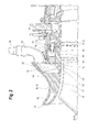
FIG. 2 is an enlarged side view of a manifold disposed within a gas turbine engine with portions sectioned and broken away to show details of the present disclosure; -
FIG. 3 is another enlarged side view of a manifold disposed within a gas turbine engine with other portions sectioned and broken away to show details of the present disclosure; -
FIG. 4 is an enlarged side view of an inlet guide vane with portions sectioned and broken away to show details of the present disclosure; -
FIG. 5 is an aft view of a manifold depicted in phantom within a housing, constructed in accordance with the teachings of this disclosure; -
FIG. 6 is a cross-sectional view taken along line 6-6 ofFIG. 5 , constructed in accordance with the teaching of this disclosure; and -
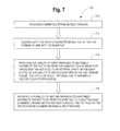
FIG. 7 is a flowchart illustrating a sample sequence of steps which may be practiced in accordance with the teachings of this disclosure. - It is to be noted that the appended drawings illustrate only typical embodiments and are therefore not to be considered limiting with respect to the scope of the disclosure or claims. Rather, the concepts of the present disclosure may apply within other equally effective embodiments. Moreover, the drawings are not necessarily to scale, emphasis generally being placed upon illustrating the principles of certain embodiments.
- Throughout this specification the terms "downstream" and "upstream" are used with reference to the general direction of gas flow through the engine and the terms "axial", "radial" and "circumferential" are generally used with respect to the longitudinal central engine axis.
- Referring now to
FIG. 1 , a gas turbine engine constructed in accordance with the present disclosure is generally referred to byreference numeral 10. Thegas turbine engine 10 includes acompressor section 12, acombustor 14 and aturbine 16. The serial combination of thecompressor section 12, thecombustor 14 and theturbine 16 is commonly referred to as acore engine 18. Thecompressor section 12 includes alow pressure compressor 20 and ahigh pressure compressor 22, which is downstream of thelow pressure compressor 20. Theengine 10 is circumscribed about a longitudinalcentral axis 24. - An
inlet particle separator 26 is located upstream of thelow pressure compressor 20.Ambient air 28 enters theinlet particle separator 26 and is bifurcated downstream at the inlethousing splitter nose 30 intobypass air 32 andengine stream air 34. Theengine stream air 34 enters thecompressor section 12 and is pressurized. The pressurized air then enters thecombustor 14. In thecombustor 14, the air mixes with jet fuel and is burned, generating hot combustion gases that flow downstream to theturbine 16. Theturbine 16 extracts energy from the hot combustion gases to drive thecompressor section 12. - With reference to
FIGS. 1-3 , the inlethousing splitter nose 30 forms the upstream circumferential end of aninlet housing 36, which circumscribes the longitudinalcentral axis 24. A plurality of struts 38 (one shown inFIG. 2 ) structurally supports and couples theinlet housing 36 to aninner wall 40 in such a way that anengine stream duct 42 is functionally defined between theinlet housing 36 and theinner wall 40. Each strut of the plurality ofstruts 38 is circumferentially spaced apart equally from one another so that the majority ofengine stream air 34 flows around thestruts 42 and downstream through theengine stream duct 42. - The
inlet housing 36 may be formed by casting and includes a contoured bypass wall 44 and an annularengine stream wall 46, which meet upstream to form the inlethousing splitter nose 30. Ahousing wall 48 radially couples the downstream ends of the contoured bypass wall 44 and theengine stream wall 46. Theinlet housing 36 also includes an internalsplitter nose chamber 50 and aninternal manifold 52. Thesplitter nose chamber 50 is separated from theinternal manifold 52 by a substantially annularsolid portion 54 of theinlet housing 36. Thesplitter nose chamber 50 is enclosed by the inlethousing splitter nose 30, the contoured bypass wall 44, theengine stream wall 46 and thesolid portion 54. Theinternal manifold 52 is enclosed by the annularengine stream wall 46, thesolid portion 54, thehousing wall 48 and an undulating wall 56 (best seen inFIG. 6 ). - An
annular flange 58 extends axially downstream from thehousing wall 48 proximate theengine stream duct 42. Anannular lip 60 also extends axially downstream from thehousing wall 48 and is disposed radially outwardly relative to theflange 58. - A plurality of inlet guide vanes 62 (one shown in
FIGS. 2-3 ) is disposed downstream of the plurality ofstruts 38 within theengine stream duct 42. Each inlet guide vane of the plurality ofinlet guide vanes 62 is circumferentially spaced apart equally from one another. Eachinlet guide vane 62 may include an airfoil 64 with aleading edge 66 facing upstream. Eachinlet guide vane 62 may also include astem 68, which extends radially outwardly from the airfoil 64. The airfoil 64 may extend between theinner wall 40 and theflange 58 within theengine stream duct 42. Thestem 68, however, extends through a corresponding sealed aperture (not shown) in theflange 58 and extends into an annular inletguide vane plenum 70. Theplenum 70 is enclosed by theflange 58, a section of thehousing wall 48, aninterconnected wall 72, and anannular plenum cover 74, which is coupled to theannular lip 60 and theinterconnected wall 72. - As best seen in
FIG. 4 , the portion of thestem 68 disposed within theplenum 70 includes aflute 76, which follows a path internally through thestem 68 leading into theairfoil cavity 78. Theairfoil cavity 78 radially extends internally through the airfoil 64 proximate to the leadingedge 66. Thestem 68 further extends through a corresponding sealed aperture (not shown) in theplenum cover 74 and this portion of thestem 68 is coupled to avane arm sweep 80, which may be actuated to position theinlet guide vane 62 to direct theengine stream air 34 in a desired direction downstream. - The
internal manifold 52 is described in more detail below with particular reference toFIGS. 2 and5-6 . Theinternal manifold 52 collects high temperature and high pressure air delivered from thehigh pressure compressor 22 via a fitting 82 and atube 84. The fitting 82 may either be welded directly to thehousing wall 48 or may be casted integrally with thehousing wall 48 allowing the hot air to enter theinternal manifold 52. The fitting 82 is coupled to thetube 84, which transfers the hot air from thehigh pressure compressor 22. The fitting 82 may be positioned at any suitable location so that thetube 84 may conveniently navigate through theengine 10 from thehigh pressure compressor 22 to the fitting 82. - A first plurality of
passages 86 is disposed through thehousing wall 48 creating paths from theinternal manifold 52 to theplenum 70. Each passage of the first plurality ofpassages 86 may be substantially circular in cross-section and is circumferentially spaced apart equally from one another. Eachpassage 86 may be proximate to acorresponding stem 68 of a correspondinginlet guide vane 62. - A second plurality of
passages 88 is disposed through thesolid portion 54 creating paths from theinternal manifold 52 to thesplitter nose chamber 50. Each passage of the second plurality ofpassages 88 may be substantially circular in cross-section. As a non-limiting example, there may be 15second passages 88 although there may be more or less. - The undulating
wall 56 of theinternal manifold 52 has a variable radial distance 90 relative to theengine stream wall 46 such that the undulatingwall 56 creates a plurality offirst chambers 92 and a plurality ofsecond chambers 94 all within theinternal manifold 52. Adjacentfirst chambers 92 are interspersed with asecond chamber 94 so that thechambers internal manifold 52 may include fivefirst chambers 92 and fivesecond chambers 94. The variable radial distance 90 includes a first variable radial distance 96 measured within each of thefirst chambers 92 and a second variable radial distance 98 measured within each of thesecond chambers 94. The first variable radial distance 96 measured substantially centrally at each of thefirst chambers 92 is greater than the second variable radial distance 98 measured substantially centrally at each of thesecond chambers 94. Thus, each of thefirst chambers 92 has a volume that is greater than each of thesecond chambers 94. Eachfirst chamber 92 gradually transitions into adjacentsecond chambers 94 such that each first variable radial distance 96 is uniform as measured along acentral portion 100 of the undulatingwall 56 within eachfirst chamber 92 and then the first variable radial distance 96 gradually decreases as measured along the undulating wall transitions 102 towards adjacentsecond chambers 94. - The second plurality of
passages 88 may be arranged through thesolid portion 54 such that eachfirst chamber 92 may include a corresponding set of threesecond passages 88, although other arrangements may also fall within the scope of the appended claims. The fitting 82 may be disposed through thehousing wall 48 to correspond with one of thefirst chambers 92. - The plurality of
first chambers 92 may be arranged so that eachfirst chamber 92 is positioned substantially betweenadjacent struts 38 while eachsecond chamber 94 is proximately aligned with acorresponding strut 38. The smaller geometry of eachsecond chamber 94 relative to eachfirst chamber 92 allows theinternal manifold 52 to avoid intersecting with otherindependent engine 10 features such as, but not limited to structural struts, passages, and tubes. - During
engine 10 operation, hot air is bled from thehigh pressure compressor 22 through thetube 84 and the fitting 82 into afirst chamber 92 of theinternal manifold 52. In order to settle the incoming air within theinternal manifold 52, the geometry of theinternal manifold 52 is calculated in correlation with the velocity of the incoming hot air fed from thehigh compressor 22. Furthermore, the geometry of the gradual volumetric transitions betweenfirst chambers 92 andsecond chambers 94 minimize undesired pressure drops within theinternal manifold 52. The air collected and circulated throughout theinternal manifold 52 is then delivered uniformly to the internalsplitter nose chamber 50 via the first plurality ofpassages 86 and delivered uniformly to theplenum 70 via the second plurality ofpassages 88. The hot air collected in theplenum 70 takes the path of least resistance to eachflute 76 of each stem 68 and then flows into eachairfoil cavity 78. The hot air within eachairfoil cavity 78 warms eachleading edge 66 to prevent ice accumulation thereon. Similarly, the hot air within the internalsplitter nose chamber 50 warms the inlethousing splitter nose 30 to prevent ice accumulation on thesplitter nose 30. -
FIG. 7 illustrates aflowchart 700 of a sample sequence of steps which may be performed to prevent ice from accumulating within a gas turbine engine.Box 710 shows the step of providing a manifold within an inlet housing. Another step, as illustrated inbox 712, is feeding hot fluid from a downstream section of the gas turbine engine into the manifold.Box 714 illustrates the step of providing a plurality of first passages to uniformly distribute the hot fluid from the manifold to a plenum that circulates the hot fluid to an internal cavity within each airfoil of a plurality of airfoils disposed in the gas turbine engine. The hot fluid in each internal cavity warms a leading edge of each airfoil. Yet another step, as shown inbox 716, is providing a plurality of second passages to uniformly distribute the hot fluid from the manifold to a splitter nose chamber disposed within the inlet housing. The hot fluid in the splitter nose chamber warms a splitter nose. Another step may be forming the manifold to include a plurality of first chambers and a plurality of second chambers so that each of the second chambers intersperse adjacent first chambers. The plurality of first chambers may be in fluid communication with the plurality of second chambers. Each first chamber may have a first volume that is greater than a second volume of each second chamber. At least a first fitting may be disposed on the manifold to feed the hot fluid into a first chamber of the plurality of first chambers. Alternatively, at least a first fitting may be casted integrally with the manifold to feed the hot fluid into a first chamber of the plurality of first chambers. The plurality of second passages may be formed into sets of three second passages so that each set of three second passages may be disposed in a corresponding first chamber of the plurality of first chambers. - While the present disclosure has shown and described details of exemplary embodiments, it will be understood by one skilled in the art that various changes in detail may be effected therein without departing from the spirit and scope of the disclosure as defined by claims supported by the written description and drawings. Further, where these exemplary embodiments (and other related derivations) are described with reference to a certain number of elements it will be understood that other exemplary embodiments may be practiced utilizing either less than or more than the certain number of elements.
- Based on the foregoing, it can be seen that the present disclosure sets forth a manifold for a gas turbine engine that prevents ice from accumulating on the inlet housing splitter nose and the leading edges of each inlet guide vane airfoil. The teachings of this disclosure can be employed to simultaneously provide a uniform distribution of hot fluid to a splitter nose chamber to warm the inlet housing splitter nose and to a plenum that circulates the hot fluid to a cavity within each inlet guide van airfoil to warm the leading edge of each airfoil. Moreover, through the novel teachings set forth above, additional heavy external plumbing and hardware is eliminated from conventional gas turbine engines to reduce overall weight and mitigate spatial constraints within the engine. The reduction of parts will, in turn, reduce costs.
Claims (15)
- A manifold (52) for a gas turbine engine (10), the manifold (52) comprising:an annular wall (46);a first wall (48) extending from the annular wall (46), the first wall (48) including a plurality of first passages (86) being disposed therethrough;a second wall (54) extending from the annular wall (46), the second wall oppositely facing the first wall, the second wall (54) including a plurality of second passages (88) being disposed therethrough; andan undulating wall (56) oppositely facing the annular wall (46) and coupling the first wall (48) to the second wall (54), wherein the undulating wall (56), the first and second walls (48, 54), and the annular wall (46) collectively form a plurality of first chambers (92) and a plurality of second chambers (94), each of the second chambers (94) interspersing adjacent first chambers (92), the plurality of first chambers (92) being in fluid communication with the plurality of second chambers (94), and each first chamber (92) having a first volume being greater than a second volume of each second chamber (94).
- The manifold (52) of claim 1, wherein the plurality of second passages (88) is arranged into sets of three second passages (88), each set of three second passages (88) is disposed in a corresponding first chamber (92) of the plurality of first chambers (92).
- The manifold (52) of claim 1 or 2, wherein the plurality of first passages (86) forms first paths to a first section of the gas turbine engine (10), and optionally wherein the plurality of first passages (86) forms first paths from the manifold (52) to a plenum (70) disposed adjacently downstream the first wall (48).
- The manifold (52) of any of claims 1 to 3, wherein the plurality of second passages (88) forms second paths to a second section of the gas turbine engine (10).
- A gas turbine engine (10), comprising:an inlet housing (36); anda manifold (52) being formed within the inlet housing (36), the manifold (52) being defined by an annular wall (46), a first wall (48), a second wall (54), and an undulating wall (56) collectively forming a plurality of first chambers (92) and a plurality of second chambers (94), each of the second chambers (94) interspersing adjacent first chambers (92), the plurality of first chambers (92) being in fluid communication with the plurality of second chambers (94), each first chamber (92) having a first volume being greater than a second volume of each second chamber (94).
- The gas turbine engine (10) of claim 5, wherein the first wall (48) includes a plurality of first passages (86) disposed therethrough and the second wall (54) includes a plurality of second passages (88) disposed therethrough, and optionally wherein the plurality of first passages (86) forms first paths from the manifold (52) to a plenum (70) disposed adjacently downstream the first wall (48).
- The gas turbine engine (10) of claim 6, wherein the plurality of second passages (88) forms second paths from the manifold (52) to a chamber (50) disposed within the inlet housing (36).
- The gas turbine engine (10) of claim 6 or 7, further including a plurality of inlet guide vanes (62) disposed downstream of the inlet housing (36), each inlet guide vane (62) of the plurality of inlet guide vanes includes an airfoil (64) and a stem (68) extending radially outwardly from the airfoil (64), the stem (68) includes a flute (76), the stem (68) and the flute (76) both contained within the plenum (70), the flute (76) forming a path from the plenum (70) to an internal cavity (78) within the airfoil (64).
- The manifold (52) or gas turbine engine (10) of any of claims 1 to 4 or 6 to 8, wherein each first passage (86) of the plurality of first passages (86) is circumferentially spaced apart equally from one another.
- The manifold (52) or gas turbine engine (10) of any preceding claim, further including at least a first fitting (82) disposed through the first wall (48) to feed fluid into a first chamber (92) of the plurality of first chambers (92).
- The manifold (52) or gas turbine engine (10) of any of claims 1 to 9, further including at least a first fitting (82) casted integrally with the first wall (48) to feed fluid into a first chamber (92) of the plurality of first chambers (92).
- A method of preventing ice from accumulating within a gas turbine engine (10), the method comprising:providing a manifold (52) within an inlet housing (36);feeding hot fluid from a downstream section of the gas turbine engine (10) into the manifold;providing a plurality of first passages (86) to uniformly distribute the hot fluid from the manifold (52) to a plenum (70) that circulates the hot fluid to an internal cavity (78) within each airfoil (64) of a plurality of airfoils (64) disposed in the gas turbine engine (10), the hot fluid in each internal cavity (78) warming a leading edge (66) of each airfoil (64); andproviding a plurality of second passages (88) to uniformly distribute the hot fluid from the manifold (52) to a splitter nose chamber (50) disposed within the inlet housing (36), the hot fluid in the splitter nose chamber (50) warming a splitter nose (30).
- The method of claim 12, further including forming the manifold (52) to include a plurality of first chambers (92) and a plurality of second chambers (94), each of the second chambers (94) interspersing adjacent first chambers (92), the plurality of first chambers (92) being in fluid communication with the plurality of second chambers (94), each first chamber (92) having a first volume being greater than a second volume of each second chamber (94).
- The method of claim 13, wherein at least a first fitting (82):disposed on the manifold (52) feeds the hot fluid into a first chamber (92) of the plurality of first chambers (92); and/orcasted integrally with the manifold (52) feeds the hot fluid into a first chamber (92) of the plurality of first chambers (92).
- The method of claim 13 or 14, wherein the plurality of second passages (88) is formed into sets of three second passages (88) and each set of three second passages (88) is disposed in a corresponding first chamber (92) of the plurality of first chambers (92).
Applications Claiming Priority (1)
| Application Number | Priority Date | Filing Date | Title |
|---|---|---|---|
| US201461992681P | 2014-05-13 | 2014-05-13 |
Publications (2)
| Publication Number | Publication Date |
|---|---|
| EP2944772A1 true EP2944772A1 (en) | 2015-11-18 |
| EP2944772B1 EP2944772B1 (en) | 2017-08-23 |
Family
ID=53175337
Family Applications (1)
| Application Number | Title | Priority Date | Filing Date |
|---|---|---|---|
| EP15167422.3A Active EP2944772B1 (en) | 2014-05-13 | 2015-05-12 | Anti-icing internal manifold for a gas turbine engine |
Country Status (2)
| Country | Link |
|---|---|
| US (1) | US9920691B2 (en) |
| EP (1) | EP2944772B1 (en) |
Cited By (2)
| Publication number | Priority date | Publication date | Assignee | Title |
|---|---|---|---|---|
| EP3444446A1 (en) * | 2017-08-14 | 2019-02-20 | General Electric Company | Inlet frame for a gas turbine engine |
| US10830135B2 (en) | 2017-08-14 | 2020-11-10 | General Electric Company Polska sp. z o.o | Inlet frame for a gas turbine engine |
Families Citing this family (3)
| Publication number | Priority date | Publication date | Assignee | Title |
|---|---|---|---|---|
| US10533497B2 (en) * | 2016-04-18 | 2020-01-14 | United Technologies Corporation | Short inlet with integrated liner anti-icing |
| US10344983B2 (en) * | 2017-06-20 | 2019-07-09 | Pratt & Whitney Canada Corp. | Assembly of tube and structure crossing multi chambers |
| US11066995B2 (en) | 2018-05-15 | 2021-07-20 | Raytheon Technologies Corporation | Gas turbine with oil warming anti-ice circuit |
Citations (5)
| Publication number | Priority date | Publication date | Assignee | Title |
|---|---|---|---|---|
| US4860534A (en) * | 1988-08-24 | 1989-08-29 | General Motors Corporation | Inlet particle separator with anti-icing means |
| US4883404A (en) * | 1988-03-11 | 1989-11-28 | Sherman Alden O | Gas turbine vanes and methods for making same |
| US20030035719A1 (en) * | 2001-08-17 | 2003-02-20 | Wadia Aspi Rustom | Booster compressor deicer |
| EP1895141A2 (en) * | 2006-07-31 | 2008-03-05 | General Electric Company | Splitter for a turbo-fan engine |
| US20080279688A1 (en) * | 2007-05-11 | 2008-11-13 | Jensen Joseph M | Heated engine nose cone using spiral channels |
Family Cites Families (10)
| Publication number | Priority date | Publication date | Assignee | Title |
|---|---|---|---|---|
| US2559851A (en) * | 1944-11-06 | 1951-07-10 | Curtiss Wright Corp | Temperature responsive coupling means for relatively rotatable conduit sections |
| GB645996A (en) * | 1948-10-21 | 1950-11-15 | Napier & Son Ltd | Improvements in or relating to air intakes for gas turbines and other internal combustion engines |
| US3933327A (en) * | 1974-08-30 | 1976-01-20 | Rohr Industries, Inc. | Aircraft anti-icing plenum |
| US5011098A (en) * | 1988-12-30 | 1991-04-30 | The Boeing Company | Thermal anti-icing system for aircraft |
| US5220785A (en) * | 1991-07-15 | 1993-06-22 | United Technologies Corporation | Side discharge anti-ice manifold |
| GB2314887B (en) * | 1996-07-02 | 2000-02-09 | Rolls Royce Plc | Ice protection for porous structure |
| FR2802573B1 (en) * | 1999-12-21 | 2002-02-15 | Aerospatiale Matra Airbus | HOT AIR DISCHARGE DEVICE FOR REACTION ENGINE AIR INTAKE COVER WITH DEFROSTING CIRCUIT |
| US7017656B2 (en) * | 2001-05-24 | 2006-03-28 | Honeywell International, Inc. | Heat exchanger with manifold tubes for stiffening and load bearing |
| US7131612B2 (en) * | 2003-07-29 | 2006-11-07 | Pratt & Whitney Canada Corp. | Nacelle inlet lip anti-icing with engine oil |
| FR2980774B1 (en) * | 2011-10-03 | 2013-10-25 | Airbus Operations Sas | AIRCRAFT NACELLE COMPRISING A HOT AIR SUPPLY DEVICE OF A PANEL COMBINING ACOUSTIC AND FROZEN TREATMENTS |
-
2015
- 2015-02-02 US US14/611,316 patent/US9920691B2/en active Active
- 2015-05-12 EP EP15167422.3A patent/EP2944772B1/en active Active
Patent Citations (5)
| Publication number | Priority date | Publication date | Assignee | Title |
|---|---|---|---|---|
| US4883404A (en) * | 1988-03-11 | 1989-11-28 | Sherman Alden O | Gas turbine vanes and methods for making same |
| US4860534A (en) * | 1988-08-24 | 1989-08-29 | General Motors Corporation | Inlet particle separator with anti-icing means |
| US20030035719A1 (en) * | 2001-08-17 | 2003-02-20 | Wadia Aspi Rustom | Booster compressor deicer |
| EP1895141A2 (en) * | 2006-07-31 | 2008-03-05 | General Electric Company | Splitter for a turbo-fan engine |
| US20080279688A1 (en) * | 2007-05-11 | 2008-11-13 | Jensen Joseph M | Heated engine nose cone using spiral channels |
Cited By (5)
| Publication number | Priority date | Publication date | Assignee | Title |
|---|---|---|---|---|
| EP3444446A1 (en) * | 2017-08-14 | 2019-02-20 | General Electric Company | Inlet frame for a gas turbine engine |
| EP3444447A1 (en) * | 2017-08-14 | 2019-02-20 | General Electric Company | Inlet frame for a gas turbine engine |
| CN109386383A (en) * | 2017-08-14 | 2019-02-26 | 通用电气公司 | Portal framework for gas-turbine unit |
| EP3699403A1 (en) * | 2017-08-14 | 2020-08-26 | General Electric Company | Method for manufacturing an inlet frame for a gas turbine engine |
| US10830135B2 (en) | 2017-08-14 | 2020-11-10 | General Electric Company Polska sp. z o.o | Inlet frame for a gas turbine engine |
Also Published As
| Publication number | Publication date |
|---|---|
| EP2944772B1 (en) | 2017-08-23 |
| US9920691B2 (en) | 2018-03-20 |
| US20150330305A1 (en) | 2015-11-19 |
Similar Documents
| Publication | Publication Date | Title |
|---|---|---|
| CN105408589B (en) | Anti-ice diverter head | |
| US10215101B2 (en) | Integrated environmental control system manifold | |
| EP2944772B1 (en) | Anti-icing internal manifold for a gas turbine engine | |
| JP6766197B2 (en) | Equipment for deicing the separator nose of aircraft turbine engines | |
| US20170204787A1 (en) | Heat exchanger array | |
| US20180283183A1 (en) | Turbine engine component with a core tie hole | |
| CN107339125A (en) | System and method for the part of cooling combustion turbine engine | |
| EP3098391A3 (en) | Turbine band anti-chording flanges | |
| CN107060905B (en) | Turbine frame cooling system and method for components in a gas turbine engine | |
| US9976431B2 (en) | Mid-turbine frame and gas turbine engine including same | |
| US10683809B2 (en) | Impeller-mounted vortex spoiler | |
| CN104662260B (en) | Transition duct and method of assembly for a turbine engine | |
| US9493244B2 (en) | Structural element of an air vehicle air intake composed of an array of passages with a hexagonal cross section | |
| US9963972B2 (en) | Mixing plenum for spoked rotors | |
| US20150354380A1 (en) | Organic matrix composite structural inlet guide vane for a turbine engine | |
| US10344598B2 (en) | Trailing edge cooling for a turbine blade | |
| US9879636B2 (en) | System of support thrust from wasted exhaust | |
| US9988935B2 (en) | Gas turbine engine with axial compressor with internal cooling pathways | |
| US20180051571A1 (en) | Airfoil for a turbine engine with porous rib | |
| US10041364B2 (en) | Inner diffuser case cone and skirt | |
| US9988943B2 (en) | Fitting for mid-turbine frame of gas turbine engine | |
| US20170328213A1 (en) | Engine component wall with a cooling circuit |
Legal Events
| Date | Code | Title | Description |
|---|---|---|---|
| PUAI | Public reference made under article 153(3) epc to a published international application that has entered the european phase |
Free format text: ORIGINAL CODE: 0009012 |
|
| AK | Designated contracting states |
Kind code of ref document: A1 Designated state(s): AL AT BE BG CH CY CZ DE DK EE ES FI FR GB GR HR HU IE IS IT LI LT LU LV MC MK MT NL NO PL PT RO RS SE SI SK SM TR |
|
| AX | Request for extension of the european patent |
Extension state: BA ME |
|
| 17P | Request for examination filed |
Effective date: 20160518 |
|
| RBV | Designated contracting states (corrected) |
Designated state(s): AL AT BE BG CH CY CZ DE DK EE ES FI FR GB GR HR HU IE IS IT LI LT LU LV MC MK MT NL NO PL PT RO RS SE SI SK SM TR |
|
| RAP1 | Party data changed (applicant data changed or rights of an application transferred) |
Owner name: UNITED TECHNOLOGIES CORPORATION |
|
| GRAP | Despatch of communication of intention to grant a patent |
Free format text: ORIGINAL CODE: EPIDOSNIGR1 |
|
| STAA | Information on the status of an ep patent application or granted ep patent |
Free format text: STATUS: GRANT OF PATENT IS INTENDED |
|
| RIC1 | Information provided on ipc code assigned before grant |
Ipc: F04D 29/56 20060101ALI20170215BHEP Ipc: F02C 7/047 20060101ALI20170215BHEP Ipc: F01D 25/02 20060101ALI20170215BHEP Ipc: F01D 17/16 20060101AFI20170215BHEP |
|
| INTG | Intention to grant announced |
Effective date: 20170228 |
|
| GRAS | Grant fee paid |
Free format text: ORIGINAL CODE: EPIDOSNIGR3 |
|
| GRAA | (expected) grant |
Free format text: ORIGINAL CODE: 0009210 |
|
| STAA | Information on the status of an ep patent application or granted ep patent |
Free format text: STATUS: THE PATENT HAS BEEN GRANTED |
|
| AK | Designated contracting states |
Kind code of ref document: B1 Designated state(s): AL AT BE BG CH CY CZ DE DK EE ES FI FR GB GR HR HU IE IS IT LI LT LU LV MC MK MT NL NO PL PT RO RS SE SI SK SM TR |
|
| REG | Reference to a national code |
Ref country code: GB Ref legal event code: FG4D |
|
| REG | Reference to a national code |
Ref country code: CH Ref legal event code: EP |
|
| REG | Reference to a national code |
Ref country code: AT Ref legal event code: REF Ref document number: 921581 Country of ref document: AT Kind code of ref document: T Effective date: 20170915 |
|
| REG | Reference to a national code |
Ref country code: IE Ref legal event code: FG4D |
|
| REG | Reference to a national code |
Ref country code: DE Ref legal event code: R096 Ref document number: 602015004229 Country of ref document: DE |
|
| REG | Reference to a national code |
Ref country code: NL Ref legal event code: MP Effective date: 20170823 |
|
| REG | Reference to a national code |
Ref country code: LT Ref legal event code: MG4D |
|
| REG | Reference to a national code |
Ref country code: AT Ref legal event code: MK05 Ref document number: 921581 Country of ref document: AT Kind code of ref document: T Effective date: 20170823 |
|
| PG25 | Lapsed in a contracting state [announced via postgrant information from national office to epo] |
Ref country code: FI Free format text: LAPSE BECAUSE OF FAILURE TO SUBMIT A TRANSLATION OF THE DESCRIPTION OR TO PAY THE FEE WITHIN THE PRESCRIBED TIME-LIMIT Effective date: 20170823 Ref country code: NL Free format text: LAPSE BECAUSE OF FAILURE TO SUBMIT A TRANSLATION OF THE DESCRIPTION OR TO PAY THE FEE WITHIN THE PRESCRIBED TIME-LIMIT Effective date: 20170823 Ref country code: HR Free format text: LAPSE BECAUSE OF FAILURE TO SUBMIT A TRANSLATION OF THE DESCRIPTION OR TO PAY THE FEE WITHIN THE PRESCRIBED TIME-LIMIT Effective date: 20170823 Ref country code: SE Free format text: LAPSE BECAUSE OF FAILURE TO SUBMIT A TRANSLATION OF THE DESCRIPTION OR TO PAY THE FEE WITHIN THE PRESCRIBED TIME-LIMIT Effective date: 20170823 Ref country code: AT Free format text: LAPSE BECAUSE OF FAILURE TO SUBMIT A TRANSLATION OF THE DESCRIPTION OR TO PAY THE FEE WITHIN THE PRESCRIBED TIME-LIMIT Effective date: 20170823 Ref country code: LT Free format text: LAPSE BECAUSE OF FAILURE TO SUBMIT A TRANSLATION OF THE DESCRIPTION OR TO PAY THE FEE WITHIN THE PRESCRIBED TIME-LIMIT Effective date: 20170823 Ref country code: NO Free format text: LAPSE BECAUSE OF FAILURE TO SUBMIT A TRANSLATION OF THE DESCRIPTION OR TO PAY THE FEE WITHIN THE PRESCRIBED TIME-LIMIT Effective date: 20171123 |
|
| PG25 | Lapsed in a contracting state [announced via postgrant information from national office to epo] |
Ref country code: ES Free format text: LAPSE BECAUSE OF FAILURE TO SUBMIT A TRANSLATION OF THE DESCRIPTION OR TO PAY THE FEE WITHIN THE PRESCRIBED TIME-LIMIT Effective date: 20170823 Ref country code: PL Free format text: LAPSE BECAUSE OF FAILURE TO SUBMIT A TRANSLATION OF THE DESCRIPTION OR TO PAY THE FEE WITHIN THE PRESCRIBED TIME-LIMIT Effective date: 20170823 Ref country code: RS Free format text: LAPSE BECAUSE OF FAILURE TO SUBMIT A TRANSLATION OF THE DESCRIPTION OR TO PAY THE FEE WITHIN THE PRESCRIBED TIME-LIMIT Effective date: 20170823 Ref country code: BG Free format text: LAPSE BECAUSE OF FAILURE TO SUBMIT A TRANSLATION OF THE DESCRIPTION OR TO PAY THE FEE WITHIN THE PRESCRIBED TIME-LIMIT Effective date: 20171123 Ref country code: LV Free format text: LAPSE BECAUSE OF FAILURE TO SUBMIT A TRANSLATION OF THE DESCRIPTION OR TO PAY THE FEE WITHIN THE PRESCRIBED TIME-LIMIT Effective date: 20170823 Ref country code: IS Free format text: LAPSE BECAUSE OF FAILURE TO SUBMIT A TRANSLATION OF THE DESCRIPTION OR TO PAY THE FEE WITHIN THE PRESCRIBED TIME-LIMIT Effective date: 20171223 Ref country code: GR Free format text: LAPSE BECAUSE OF FAILURE TO SUBMIT A TRANSLATION OF THE DESCRIPTION OR TO PAY THE FEE WITHIN THE PRESCRIBED TIME-LIMIT Effective date: 20171124 |
|
| REG | Reference to a national code |
Ref country code: FR Ref legal event code: PLFP Year of fee payment: 4 |
|
| PG25 | Lapsed in a contracting state [announced via postgrant information from national office to epo] |
Ref country code: RO Free format text: LAPSE BECAUSE OF FAILURE TO SUBMIT A TRANSLATION OF THE DESCRIPTION OR TO PAY THE FEE WITHIN THE PRESCRIBED TIME-LIMIT Effective date: 20170823 Ref country code: DK Free format text: LAPSE BECAUSE OF FAILURE TO SUBMIT A TRANSLATION OF THE DESCRIPTION OR TO PAY THE FEE WITHIN THE PRESCRIBED TIME-LIMIT Effective date: 20170823 Ref country code: CZ Free format text: LAPSE BECAUSE OF FAILURE TO SUBMIT A TRANSLATION OF THE DESCRIPTION OR TO PAY THE FEE WITHIN THE PRESCRIBED TIME-LIMIT Effective date: 20170823 |
|
| REG | Reference to a national code |
Ref country code: DE Ref legal event code: R097 Ref document number: 602015004229 Country of ref document: DE |
|
| PG25 | Lapsed in a contracting state [announced via postgrant information from national office to epo] |
Ref country code: SM Free format text: LAPSE BECAUSE OF FAILURE TO SUBMIT A TRANSLATION OF THE DESCRIPTION OR TO PAY THE FEE WITHIN THE PRESCRIBED TIME-LIMIT Effective date: 20170823 Ref country code: SK Free format text: LAPSE BECAUSE OF FAILURE TO SUBMIT A TRANSLATION OF THE DESCRIPTION OR TO PAY THE FEE WITHIN THE PRESCRIBED TIME-LIMIT Effective date: 20170823 Ref country code: EE Free format text: LAPSE BECAUSE OF FAILURE TO SUBMIT A TRANSLATION OF THE DESCRIPTION OR TO PAY THE FEE WITHIN THE PRESCRIBED TIME-LIMIT Effective date: 20170823 Ref country code: IT Free format text: LAPSE BECAUSE OF FAILURE TO SUBMIT A TRANSLATION OF THE DESCRIPTION OR TO PAY THE FEE WITHIN THE PRESCRIBED TIME-LIMIT Effective date: 20170823 |
|
| PLBE | No opposition filed within time limit |
Free format text: ORIGINAL CODE: 0009261 |
|
| STAA | Information on the status of an ep patent application or granted ep patent |
Free format text: STATUS: NO OPPOSITION FILED WITHIN TIME LIMIT |
|
| 26N | No opposition filed |
Effective date: 20180524 |
|
| PG25 | Lapsed in a contracting state [announced via postgrant information from national office to epo] |
Ref country code: SI Free format text: LAPSE BECAUSE OF FAILURE TO SUBMIT A TRANSLATION OF THE DESCRIPTION OR TO PAY THE FEE WITHIN THE PRESCRIBED TIME-LIMIT Effective date: 20170823 |
|
| REG | Reference to a national code |
Ref country code: CH Ref legal event code: PL |
|
| REG | Reference to a national code |
Ref country code: BE Ref legal event code: MM Effective date: 20180531 |
|
| PG25 | Lapsed in a contracting state [announced via postgrant information from national office to epo] |
Ref country code: MC Free format text: LAPSE BECAUSE OF FAILURE TO SUBMIT A TRANSLATION OF THE DESCRIPTION OR TO PAY THE FEE WITHIN THE PRESCRIBED TIME-LIMIT Effective date: 20170823 |
|
| REG | Reference to a national code |
Ref country code: IE Ref legal event code: MM4A |
|
| PG25 | Lapsed in a contracting state [announced via postgrant information from national office to epo] |
Ref country code: CH Free format text: LAPSE BECAUSE OF NON-PAYMENT OF DUE FEES Effective date: 20180531 Ref country code: LI Free format text: LAPSE BECAUSE OF NON-PAYMENT OF DUE FEES Effective date: 20180531 |
|
| PG25 | Lapsed in a contracting state [announced via postgrant information from national office to epo] |
Ref country code: LU Free format text: LAPSE BECAUSE OF NON-PAYMENT OF DUE FEES Effective date: 20180512 |
|
| PG25 | Lapsed in a contracting state [announced via postgrant information from national office to epo] |
Ref country code: IE Free format text: LAPSE BECAUSE OF NON-PAYMENT OF DUE FEES Effective date: 20180512 |
|
| PG25 | Lapsed in a contracting state [announced via postgrant information from national office to epo] |
Ref country code: BE Free format text: LAPSE BECAUSE OF NON-PAYMENT OF DUE FEES Effective date: 20180531 |
|
| PG25 | Lapsed in a contracting state [announced via postgrant information from national office to epo] |
Ref country code: MT Free format text: LAPSE BECAUSE OF NON-PAYMENT OF DUE FEES Effective date: 20180512 |
|
| PG25 | Lapsed in a contracting state [announced via postgrant information from national office to epo] |
Ref country code: TR Free format text: LAPSE BECAUSE OF FAILURE TO SUBMIT A TRANSLATION OF THE DESCRIPTION OR TO PAY THE FEE WITHIN THE PRESCRIBED TIME-LIMIT Effective date: 20170823 |
|
| PG25 | Lapsed in a contracting state [announced via postgrant information from national office to epo] |
Ref country code: PT Free format text: LAPSE BECAUSE OF FAILURE TO SUBMIT A TRANSLATION OF THE DESCRIPTION OR TO PAY THE FEE WITHIN THE PRESCRIBED TIME-LIMIT Effective date: 20170823 |
|
| PG25 | Lapsed in a contracting state [announced via postgrant information from national office to epo] |
Ref country code: CY Free format text: LAPSE BECAUSE OF FAILURE TO SUBMIT A TRANSLATION OF THE DESCRIPTION OR TO PAY THE FEE WITHIN THE PRESCRIBED TIME-LIMIT Effective date: 20170823 Ref country code: HU Free format text: LAPSE BECAUSE OF FAILURE TO SUBMIT A TRANSLATION OF THE DESCRIPTION OR TO PAY THE FEE WITHIN THE PRESCRIBED TIME-LIMIT; INVALID AB INITIO Effective date: 20150512 Ref country code: MK Free format text: LAPSE BECAUSE OF NON-PAYMENT OF DUE FEES Effective date: 20170823 |
|
| PG25 | Lapsed in a contracting state [announced via postgrant information from national office to epo] |
Ref country code: AL Free format text: LAPSE BECAUSE OF FAILURE TO SUBMIT A TRANSLATION OF THE DESCRIPTION OR TO PAY THE FEE WITHIN THE PRESCRIBED TIME-LIMIT Effective date: 20170823 |
|
| REG | Reference to a national code |
Ref country code: DE Ref legal event code: R081 Ref document number: 602015004229 Country of ref document: DE Owner name: RAYTHEON TECHNOLOGIES CORPORATION (N.D.GES.D.S, US Free format text: FORMER OWNER: UNITED TECHNOLOGIES CORPORATION, FARMINGTON, CONN., US Ref country code: DE Ref legal event code: R081 Ref document number: 602015004229 Country of ref document: DE Owner name: RTX CORPORATION (N.D.GES.D. STAATES DELAWARE),, US Free format text: FORMER OWNER: UNITED TECHNOLOGIES CORPORATION, FARMINGTON, CONN., US |
|
| P01 | Opt-out of the competence of the unified patent court (upc) registered |
Effective date: 20230520 |
|
| PGFP | Annual fee paid to national office [announced via postgrant information from national office to epo] |
Ref country code: DE Payment date: 20250423 Year of fee payment: 11 |
|
| PGFP | Annual fee paid to national office [announced via postgrant information from national office to epo] |
Ref country code: GB Payment date: 20250423 Year of fee payment: 11 |
|
| PGFP | Annual fee paid to national office [announced via postgrant information from national office to epo] |
Ref country code: FR Payment date: 20250423 Year of fee payment: 11 |
|
| REG | Reference to a national code |
Ref country code: DE Ref legal event code: R081 Ref document number: 602015004229 Country of ref document: DE Owner name: RTX CORPORATION (N.D.GES.D. STAATES DELAWARE),, US Free format text: FORMER OWNER: RAYTHEON TECHNOLOGIES CORPORATION (N.D.GES.D.STAATES DELAWARE), ARLINGTON, VA, US |