EP2944564A1 - Load-bearing fairing element for a flap adjustment mechanism and aircraft having such a fairing element - Google Patents
Load-bearing fairing element for a flap adjustment mechanism and aircraft having such a fairing element Download PDFInfo
- Publication number
- EP2944564A1 EP2944564A1 EP15167559.2A EP15167559A EP2944564A1 EP 2944564 A1 EP2944564 A1 EP 2944564A1 EP 15167559 A EP15167559 A EP 15167559A EP 2944564 A1 EP2944564 A1 EP 2944564A1
- Authority
- EP
- European Patent Office
- Prior art keywords
- fairing
- housing
- bridge element
- fairing housing
- main extension
- Prior art date
- Legal status (The legal status is an assumption and is not a legal conclusion. Google has not performed a legal analysis and makes no representation as to the accuracy of the status listed.)
- Granted
Links
Images


Classifications
-
- B—PERFORMING OPERATIONS; TRANSPORTING
- B64—AIRCRAFT; AVIATION; COSMONAUTICS
- B64C—AEROPLANES; HELICOPTERS
- B64C9/00—Adjustable control surfaces or members, e.g. rudders
- B64C9/14—Adjustable control surfaces or members, e.g. rudders forming slots
- B64C9/22—Adjustable control surfaces or members, e.g. rudders forming slots at the front of the wing
-
- B—PERFORMING OPERATIONS; TRANSPORTING
- B64—AIRCRAFT; AVIATION; COSMONAUTICS
- B64C—AEROPLANES; HELICOPTERS
- B64C7/00—Structures or fairings not otherwise provided for
-
- B—PERFORMING OPERATIONS; TRANSPORTING
- B64—AIRCRAFT; AVIATION; COSMONAUTICS
- B64C—AEROPLANES; HELICOPTERS
- B64C9/00—Adjustable control surfaces or members, e.g. rudders
- B64C9/02—Mounting or supporting thereof
-
- B—PERFORMING OPERATIONS; TRANSPORTING
- B64—AIRCRAFT; AVIATION; COSMONAUTICS
- B64C—AEROPLANES; HELICOPTERS
- B64C9/00—Adjustable control surfaces or members, e.g. rudders
- B64C9/14—Adjustable control surfaces or members, e.g. rudders forming slots
- B64C9/16—Adjustable control surfaces or members, e.g. rudders forming slots at the rear of the wing
-
- Y—GENERAL TAGGING OF NEW TECHNOLOGICAL DEVELOPMENTS; GENERAL TAGGING OF CROSS-SECTIONAL TECHNOLOGIES SPANNING OVER SEVERAL SECTIONS OF THE IPC; TECHNICAL SUBJECTS COVERED BY FORMER USPC CROSS-REFERENCE ART COLLECTIONS [XRACs] AND DIGESTS
- Y02—TECHNOLOGIES OR APPLICATIONS FOR MITIGATION OR ADAPTATION AGAINST CLIMATE CHANGE
- Y02T—CLIMATE CHANGE MITIGATION TECHNOLOGIES RELATED TO TRANSPORTATION
- Y02T50/00—Aeronautics or air transport
- Y02T50/40—Weight reduction
Definitions
- the invention relates to a load-bearing fairing element for a flap adjustment mechanism of an aircraft and to an aircraft comprising at least one adjustable flap, a flap adjustment mechanism coupled thereto, and a load-bearing fairing element.
- aircraft For the purpose of controlling flight, aircraft usually comprise adjustable flaps that are rotatorily and/or translatorily moved by way of actuators.
- high-lift flaps carry out a very substantial translatory and at the same time rotatory movement relative to the wing.
- the adjustment mechanism used for this is frequently driven by a central power control unit in the region of a wing root, which power control unit is coupled, by way of a gear shaft, to the adjustment mechanism.
- spindle gear arrangements are used in the adjustment mechanism, in which spindle gear arrangements a driven rotary spindle engages a spindle nut and slides this spindle nut along the longitudinal axis of the spindle. Because of its size, the adjustment mechanism often projects beyond the underside of the wing on which the adjustable flap is arranged, and is aerodynamically enclosed by a fairing element.
- Such a fairing element is, for example, known from DE 10 2007 048 449 A1 , which comprises a load-bearing structure with a multitude of separately manufactured stiffening elements that fulfill a load-bearing function for the adjustment mechanism.
- the fairing element comprises a shell-shaped fairing housing with an at least partly U-shaped profile with an open side, a closed side and a direction of main extension; at least one first cover panel that along the direction of main extension covers part of the open side; and a load-bearing bridge element, wherein the bridge element is arranged in a second section of the direction of main extension in the fairing housing, with a base area conforms so as to be flush against an internal surface of the fairing housing and extends towards the open side, and an essentially planar cover area that covers the base area on the open side in order to produce a closed profile contour that is circumferential on the direction of main extension.
- the bridge element comprises means for holding a shaft feed-in of a central flap drive and means for holding an adjustment mechanism that is couplable to the shaft feed-in.
- the shell-shaped fairing housing provides the outer shape that, in particular, determines the aerodynamic characteristics of the fairing.
- the extension of the fairing housing is determined by the size of the adjustment mechanism; according to the extension said fairing can be a housing closed off per se or it can form part of a larger housing.
- a further housing part may be arranged on the high-lift flap to be moved, which high lift flap carries out a translatory and/or a rotatory movement. So as not to impede this, the fairing housing is pivotally coupled to another fairing housing so as not to impede this pivoting movement of the adjustment mechanism.
- manufacturing the fairing housing in particular from a fiber composite material suggests itself.
- the profile of the fairing housing at least in parts comprises a U-shape, wherein the limbs of the U-profile form the lateral walls, and the arc extending between the limbs establishes an aerodynamically advantageous transition between the lateral walls.
- U-profile is not to be narrowly interpreted as having two limbs that extend exactly parallel to each other. Instead, the term “U-profile” refers to a rounded, preferably symmetrical and geometrically in particular simple profile that on one side is closed by a type or arc, and on the other side is open so that in this manner a fairing housing is implemented that is open on one side and is overall shell-shaped.
- the direction of main extension of the fairing element may be a longitudinal axis of the fairing element.
- the fairing housing can be divided into several imaginary sections that are strung together in the direction of main extension.
- the axis of main extension may, in particular, be a longitudinal axis because the fairing housing is usually elongated in shape and is aligned parallel to the expected direction of flow.
- the first cover panel is used as a thrust plate; it contributes to the provision of adequate stiffness of the fairing housing, in particular in terms of torsion loads and bending loads. It is thus necessary for a fixed connection on the edge to exist between the first cover panel and the fairing housing. To this effect strip-like flanges that extend perpendicularly to the first cover panel suggest themselves, which flanges make it possible to bond or rivet the first cover panel to the fairing housing with the use of adequate surface contact.
- the bridge element acts as a multifunctional connecting link between a wing, a shaft feed-in and an adjustment mechanism for a flap and is integrated as a compact unit in the fairing element.
- the bridge element may act as a central load introduction element for the adjustment mechanism.
- the bridge element may be separately adapted to absorb the loads that arise in the interaction between the controlled flap, the wing, and the fairing element, and may introduce these loads into the fairing housing, in particular through a boundary surface between the base area of the bridge element and the internal surface of the fairing housing.
- the circumferential closed profile contour supports the inherent strength of the bridge element and moreover by way of the planar cover area allows simple attachment to a wing. However, this need not be the only attachment; in addition, further regions of the fairing element is connectable to the wing.
- a core aspect of the invention thus consists of the separation of functions for the structural stiffening of a fairing housing and of functions that relate to the load introduction or the load absorption in conjunction with the adjustment mechanism of the associated flap. While consequently the bridge element integrated in the structurally-stiffened fairing housing may be ideally adapted to the load introduction, the fairing housing per se is independent of this task and may consequently also be manufactured independently hereof in a significantly simpler manufacturing process. In particular, this makes possible the manufacture with the use of an adapted material, for example a fiber composite material, in a comparatively simple work process.
- the fairing housing is made from a fiber composite material and comprises at least one integral stiffening component.
- a fiber composite material supports a particularly flexible design, wherein already during the manufacturing process all the stiffening components necessary to ensure rigidity of the fairing housing may be directly integrated. The separate placement of, in particular, metallic, sheet-metal-like components may thus be avoided.
- a stiffening component may, for example, be a rib, a frame element, a stringer, or a combination thereof.
- a stiffening component in a region where the expected mechanical tension is relatively low may also comprise a recess in order to save weight.
- the fairing housing furthermore comprises at least one connection means that is designed to establish a mechanical connection with a wing.
- a connection means may be made available in the form of a separately provided component that comprises a flange or an aperture, so that by way of mechanical connecting elements, adhesive or the like a mechanical connection with a wing may be established.
- the connection means should be reachable from the open side of the fairing housing.
- the connection means may, however, also be integrated in an already provided stiffening component, or may be integrated in the fairing housing as a separate component.
- the fairing housing in a region close to the leading edge of the fairing element, comprises a multitude of ribs that are spaced apart from each other, which ribs are arranged transversely to the direction of main extension.
- ribs refers to flat components that from the closed side of the fairing housing extend at least in part towards the open side and comprise a through opening or a surface comprising an opening so that stiffening of this region takes place.
- the ribs may be produced in the form of pre-compacted or pre-cured composite structures and during the process of curing of the fairing housing may be cured together with said fairing housing.
- transitions between the internal surface of the fairing housing and the pre-cured or pre-compacted composite structures situated thereon may be lined with the use of widths comprising a resin-impregnated fiber fabric.
- connection means may, for example, be integrated in one or several of these ribs in order to establish a connection between a wing and an end of a rib, which end faces the open side of the fairing housing.
- the rib in which a connection means is integrated, may have a dimension that differs from that of the other ribs, and may, for example, extend further towards the open side of the fairing housing than is the case with adjacent ribs.
- several or all the ribs may comprise this connection means. Apart from the attachment to the cover area of the bridge element this allows additional securing of the leading edge of the fairing element to the wing.
- the fairing housing On its internal surface the fairing housing preferably comprises a load introduction region in which the bridge element is integrally connected to the fairing housing.
- the placement of an adhesive or resin may take place so that, after corresponding curing, a solid connection between the fairing housing and the bridge element is present.
- the bridge element may be positioned therein and, as a result of the curing of the resin from the fiber composite material, may be connected to the fairing housing during curing. Consequently, this obviates the need, in particular, of any subsequent processing of the boundary surface between the bridge element and the fairing housing.
- the load introduction region may be delimited in at least one direction along the direction of main extension by means of at least one flat flange.
- the aforesaid may be implemented in the form of a rib or of a frame element that apart from circumferential stiffening also provides means for attaching the bridge element.
- the surface of the load introduction region and the base area may be provided with a desired surface roughness and/or a desired fit with the use of a grinding process or some other material-removing processes so that the bridge element may be securely connected to the fairing housing.
- the bridge element may comprise at least one connecting region that corresponds to a connecting region of the fairing housing, wherein the connecting regions are matched in such a manner that positive-locking or non-positive-locking connecting elements may be used to connect them. Consequently, the bridge element may be connected to the fairing housing with the use of screw connections or rivet connections.
- the connecting regions may, in particular, comprise strip-shaped surface regions or flanges, which are preferably circumferential around the direction of extension, and/or extend along the direction of extension, so that, for example rivets or screws may be used in dedicated connection regions that overlap each other.
- the bridge element has been manufactured from a metallic material.
- a metallic material may, in particular, comprise an aluminum alloy, magnesium alloy or titanium, which is, in particular, tailored to the stress to which it will be subjected, so that adequate strength and at the same time the lightest possible weight result.
- the design of the bridge element may include the separate manufacture of individual components and their joining by conventional joining techniques. However, it would also be imaginable to manufacture more complex and weight-optimized structures in a layered construction process, which structures form a bridge element. The material-removing processing of a solid metal block and the casting of the bridge element are further imaginable variants.
- the fairing element comprises a second cover panel, arranged along the direction of main extension on an end of the bridge element, which end is opposite the first cover panel.
- the second cover panel also acts as a thrust plate and contributes to the stiffness of the region of the fairing housing, which region is covered by said second cover panel.
- Each of the above-mentioned cover panels may also be made of a metallic material, which may be integrated in the fairing housing by means of riveting, bonding, or mutual curing. Of course, it would also be imaginable to produce the cover panels from a fiber composite material, both as integral components and as separately manufactured and attachable components.
- the at least one access opening in the fairing housing that is dimensioned in such a manner that a human hand may reach through the access opening into the interior of the fairing housing in order to access components located in the fairing housing. It is thus easily possible for a person to inspect the interior of the fairing element, to carry out maintenance work, or to support the installation of components.
- the at least one access opening should be designed so as to be closable with the use of a cover, wherein due to the expected flow speeds the cover is preferably screwed to the fairing housing.
- At least one of the at least one access opening in the fairing housing is aligned with an access opening in the bridge element.
- the bridge element may consequently comprise a configuration that cannot, or need not, subsequently be taken apart.
- the bridge element may thus also act as an integral stiffening device of the fairing housing in the region around the access holes.
- the fairing element comprises at least one access opening, wherein these access openings may be arranged symmetrically or so as to correspond to each other. In particular for installation and maintenance, access on both sides is possible.
- At least one of the at least one access opening comprises an annular thickening on the edge. This is used as a mechanical reinforcement in order to prevent stress peaks in the edge region, which stress peaks may result in damage to the fairing housing when the latter is subject to mechanical loads.
- the bridge element comprises an annular thickening in a region in which access opening of the fairing housing is situated, in order to be integrated in the bridge element as additional reinforcement.
- the invention relates to an aircraft comprising a wing and at least one flap arranged so as to be movable relative to said wing, further comprising at least one adjustment mechanism that is arranged in an above-mentioned fairing element that is attached to the wing.
- the method for manufacturing a fairing element may be implemented in various ways. They differ, in particular, by the selected concept of curing, pre-curing or pre-compacting of one or several sub-regions of the fairing housing or of the fairing element. Proposed is a basic method that comprises the steps of providing a shell-shaped fairing housing, at least one first cover panel and a bridge element, and the joining and connecting of these components.
- providing the fairing housing involves placing a raw component of a resin-containing fiber material in a mold, pre-curing or pre-compacting, and incorporating at least one stiffening component.
- Incorporating the stiffening component may involve shaping the at least one stiffening component in the raw component as well as the incorporation of a pre-cured or pre-compacted stiffening component.
- Joining the fairing housing, the at least one first cover panel, and the bridge element may involve inserting or placing these components into or onto the pre-cured or pre-compacted fairing housing as well as subsequent curing with an adhesive or resin present between the components.
- the fairing housing may also be fully cured, and the at least one first cover panel and the bridge element may subsequently be put into place and may be bonded or connected in a positive-locking, non-positive-locking, or integral manner.
- FIGs 1a and 1b show a fairing element 2 for a flap adjustment mechanism (not shown in the diagrams) of an aircraft.
- Said fairing element 2 comprises a shell-shaped fairing housing 4, which over a significant part along the direction of main extension (x) comprises a U-shaped profile that in the drawing plane is closed at the bottom and open at the top.
- the fairing housing 4 comprises a fiber composite material, for example CFRP. In this manner it is possible to achieve an aerodynamically very favorable profile without incurring an excessively laborious or costly manufacturing effort.
- the fairing element 2 which comprises an adjustment mechanism and a flap driven by the aforesaid, is attachable, by way of a front section 3, to the underside of a wing.
- This front section is separated, by a kink 7, from a rear section 5 against which the driven flap may rest.
- a number of additional components are integrated in the fairing housing 4, for example the approximately half-moon-shaped ribs 6 in a region close to the leading edge 11 of the fairing element 2, which components, by means of holes 7 pointing towards the open side, may establish a redundant, secure mechanical connection with a main wing.
- a front frame element 8 and a rear frame element 10 are shown with an aperture 12 for an articulated connection to a further fairing element adjoining said rear frame element 10.
- All of these additional elements are preferably made from the same material as the fairing housing 4 itself. It suggests itself, in particular, to manufacture the fairing housing 4, with the stiffening elements 6, 8 and 10 integrated therein, in such a manner that all the components cure together, thus forming one integral component.
- the individual ribs 6 may be produced, pre-cured or pre-compacted from a resin-impregnated fiber fabric and may then be placed into a pre-compacted composite structure that will subsequently form the fairing housing 4. The same applies to the frame elements 8 and 10.
- a first cover panel 14 and a second cover panel 16 are inserted as thrust plates on the open side of the fairing housing 4, where they are attached. Attachment may also take place by mutual curing if the cover panels 14 and 16 also comprise a fiber composite material. However, if these elements have been made from a metallic material, they may subsequently be bonded, screwed or riveted into place or may be arranged in such a manner in the curing process that during the curing process of the fairing housing 4 adhesion to the cover panels 14 and 16 takes place.
- the stiffening function of the cover panels 14 and 16 may also be achieved when the apertures 18, 20 and 22 are generous in size.
- the so-called bridge element 24 is a central component that, for example, is arranged approximately in the middle of the fairing element 2, with the cover panels 14 and 16 adjoining said bridge element 24.
- the bridge element 24 has a shape that matches the shape of the fairing housing 4. This means that it has a U-shaped base area 26 that rests against an internal surface 28 of the fairing housing 4.
- the bridge element 24 extends to the open side of the fairing housing 4, where it comprises a planar cover area 30 that closes the bridge element 24.
- the bridge element 24 thus comprises a profile that is circumferential on the direction of main extension (x).
- the bridge element 24 may comprise a connecting region 25 that corresponds to a connecting region 27 in the fairing housing 4.
- a connecting region 27 in the fairing housing 4.
- an edge region on the open side of the fairing housing 4 and of a region corresponding to it is shown as connecting regions 25 and 27.
- one or several webs extending around the direction of extension (x) on the fairing housing 4 and on the bridge element 24 may be used as further connecting regions 25, 27.
- the bridge element 24 is preferably made from a metallic material; it may, for example, be milled from a solid aluminum block, as an alternative to this it may also be manufactured component by component and may be connected, with the use of welded connections or riveted connections, to form a bridge element 24.
- a layer by layer design of a bridge element 24 comprising a more complex shape would also be possible, for example by means of an ALM method or an SLM method in which a metal powder is put in place and cured, and subsequently the resulting component is treated, for example in a heat treatment process.
- an angle gear may be held which may be coupled, by way of a shaft feed-in 32, to a shaft of a central power control unit, (PCU).
- the angle gear may drive a spindle (not shown in Figures 1a and 1b ) that engages a spindle nut in order to carry out a defined movement.
- apertures 34 and 36 are arranged in the fairing housing 4, which apertures 34 and 36 are dimensioned in such a manner that a human hand and the components to be maintained may be fed through them.
- the rear aperture 34 has a diameter of more than 10 cm, in particular 13 to 16 cm or more.
- the middle aperture 36 which is furthermore aligned with an aperture in the base area 26 of the bridge element 24.
- screw-type covers are used that are preferably designed to be non-load-bearing and consequently are practically not subjected to mechanical loads.
- an additional aperture 37 in particular for the installation and maintenance of an actuator that may be arranged on the side of the bridge element 24, which side faces the ribs 6.
- the aperture 37 is rectangular with rounded corners. This may, for example, make it possible to insert into the fairing housing 4 an actuator comprising a rectangular housing, and to attach said actuator in that location. In particular through the access opening 36, which is located beside the rectangular access opening 37, a hand may be inserted to support and guide the actuator.
- local, annular thickenings 38 or 40 are incorporated in the material of the fairing housing 4 so that the stress, which results in that location as a result of torsional forces or bending forces acting on the fairing housing 4, may be reduced. Furthermore, the thickenings may prevent mechanical loads acting on the covers of the apertures.
- the fairing element 2 is shown so as to be transparent in parts.
- This view shows an aperture 42 in the bridge element 24, which aperture 42 is aligned with the aperture 36 of the fairing housing 4.
- the illustration shows an overlap of an edge surface 44 of the second cover panel with an edge surface 46 of the bridge element 24.
- said first cover panel 14 extends above the frame element 8 and, for example, does not establish contact with said frame element 8.
- the ribs 6, the frame element 8 and the frame element 10 form integral parts of the fairing housing 4.
- FIG 3 shows a view A, designated "A" in Figure 1a , with an adjustment mechanism 51 comprising an angle gear 48 that is integrated in the bridge element 24 and, by way of a shaft connection 32, may be coupled to a central flap drive. From the rotation of the shaft connection 32 the angle gear 48 may implement rotation of a threaded spindle 50 on which a threaded nut 52 is arranged. The latter acts on a lever 54 that is responsible for movement of a kinematic element coupled to it. Since the function of the fairing element 2 does not depend on the adjustment mechanism per se, no further details are shown in this context.
- a particularly advantageous fairing element 2 for an adjustment mechanism on a wing of an aircraft results, which fairing element 2 is load-bearing, simple to manufacture and features light weight.
Landscapes
- Engineering & Computer Science (AREA)
- Aviation & Aerospace Engineering (AREA)
- Moulding By Coating Moulds (AREA)
Abstract
Description
- The invention relates to a load-bearing fairing element for a flap adjustment mechanism of an aircraft and to an aircraft comprising at least one adjustable flap, a flap adjustment mechanism coupled thereto, and a load-bearing fairing element.
- For the purpose of controlling flight, aircraft usually comprise adjustable flaps that are rotatorily and/or translatorily moved by way of actuators. In particular, high-lift flaps carry out a very substantial translatory and at the same time rotatory movement relative to the wing. The adjustment mechanism used for this is frequently driven by a central power control unit in the region of a wing root, which power control unit is coupled, by way of a gear shaft, to the adjustment mechanism. Often, spindle gear arrangements are used in the adjustment mechanism, in which spindle gear arrangements a driven rotary spindle engages a spindle nut and slides this spindle nut along the longitudinal axis of the spindle. Because of its size, the adjustment mechanism often projects beyond the underside of the wing on which the adjustable flap is arranged, and is aerodynamically enclosed by a fairing element.
- Such a fairing element is, for example, known from
DE 10 2007 048 449 A1 - The integration of a multitude of stiffening elements in a fairing element and the placement of mechanical components for the adjustment mechanism result in costly and elaborate manufacture. Individual stiffening elements need to be produced separately and need to be individually connected to a shell-like, aerodynamically shaped element in order to in this manner construct a load-bearing fairing element.
- It is an object of the invention to propose a fairing element that may be manufactured particularly economically without there being a need to do without the positive aerodynamic characteristics, a lightweight construction, or the load-bearing function.
- This object is met by a fairing element with the characteristics of the independent claim 1. Advantageous embodiments and improvements are stated in the subordinate claims and in the following description.
- Proposed is a load-bearing fairing element for a flap adjustment mechanism of an aircraft. The fairing element comprises a shell-shaped fairing housing with an at least partly U-shaped profile with an open side, a closed side and a direction of main extension; at least one first cover panel that along the direction of main extension covers part of the open side; and a load-bearing bridge element, wherein the bridge element is arranged in a second section of the direction of main extension in the fairing housing, with a base area conforms so as to be flush against an internal surface of the fairing housing and extends towards the open side, and an essentially planar cover area that covers the base area on the open side in order to produce a closed profile contour that is circumferential on the direction of main extension. The bridge element comprises means for holding a shaft feed-in of a central flap drive and means for holding an adjustment mechanism that is couplable to the shaft feed-in.
- The shell-shaped fairing housing provides the outer shape that, in particular, determines the aerodynamic characteristics of the fairing. The extension of the fairing housing is determined by the size of the adjustment mechanism; according to the extension said fairing can be a housing closed off per se or it can form part of a larger housing. In particular, a further housing part may be arranged on the high-lift flap to be moved, which high lift flap carries out a translatory and/or a rotatory movement. So as not to impede this, the fairing housing is pivotally coupled to another fairing housing so as not to impede this pivoting movement of the adjustment mechanism. To be able to provide as free and flexible a shape as possible, manufacturing the fairing housing in particular from a fiber composite material suggests itself.
- The profile of the fairing housing at least in parts comprises a U-shape, wherein the limbs of the U-profile form the lateral walls, and the arc extending between the limbs establishes an aerodynamically advantageous transition between the lateral walls. In actual fact the term "U-profile" is not to be narrowly interpreted as having two limbs that extend exactly parallel to each other. Instead, the term "U-profile" refers to a rounded, preferably symmetrical and geometrically in particular simple profile that on one side is closed by a type or arc, and on the other side is open so that in this manner a fairing housing is implemented that is open on one side and is overall shell-shaped.
- Since such fairing elements usually comprise an elongated structure, the direction of main extension of the fairing element may be a longitudinal axis of the fairing element. The fairing housing can be divided into several imaginary sections that are strung together in the direction of main extension. The axis of main extension may, in particular, be a longitudinal axis because the fairing housing is usually elongated in shape and is aligned parallel to the expected direction of flow.
- The first cover panel is used as a thrust plate; it contributes to the provision of adequate stiffness of the fairing housing, in particular in terms of torsion loads and bending loads. It is thus necessary for a fixed connection on the edge to exist between the first cover panel and the fairing housing. To this effect strip-like flanges that extend perpendicularly to the first cover panel suggest themselves, which flanges make it possible to bond or rivet the first cover panel to the fairing housing with the use of adequate surface contact.
- For the load-bearing fairing element the bridge element acts as a multifunctional connecting link between a wing, a shaft feed-in and an adjustment mechanism for a flap and is integrated as a compact unit in the fairing element. By carrying out several tasks the bridge element may act as a central load introduction element for the adjustment mechanism. In terms of materials characteristics, the bridge element may be separately adapted to absorb the loads that arise in the interaction between the controlled flap, the wing, and the fairing element, and may introduce these loads into the fairing housing, in particular through a boundary surface between the base area of the bridge element and the internal surface of the fairing housing. The circumferential closed profile contour supports the inherent strength of the bridge element and moreover by way of the planar cover area allows simple attachment to a wing. However, this need not be the only attachment; in addition, further regions of the fairing element is connectable to the wing.
- A core aspect of the invention thus consists of the separation of functions for the structural stiffening of a fairing housing and of functions that relate to the load introduction or the load absorption in conjunction with the adjustment mechanism of the associated flap. While consequently the bridge element integrated in the structurally-stiffened fairing housing may be ideally adapted to the load introduction, the fairing housing per se is independent of this task and may consequently also be manufactured independently hereof in a significantly simpler manufacturing process. In particular, this makes possible the manufacture with the use of an adapted material, for example a fiber composite material, in a comparatively simple work process.
- In a particularly advantageous embodiment the fairing housing is made from a fiber composite material and comprises at least one integral stiffening component. A fiber composite material supports a particularly flexible design, wherein already during the manufacturing process all the stiffening components necessary to ensure rigidity of the fairing housing may be directly integrated. The separate placement of, in particular, metallic, sheet-metal-like components may thus be avoided. A stiffening component may, for example, be a rib, a frame element, a stringer, or a combination thereof. Of course, a stiffening component in a region where the expected mechanical tension is relatively low may also comprise a recess in order to save weight.
- Preferably, the fairing housing furthermore comprises at least one connection means that is designed to establish a mechanical connection with a wing. A connection means may be made available in the form of a separately provided component that comprises a flange or an aperture, so that by way of mechanical connecting elements, adhesive or the like a mechanical connection with a wing may be established. In this arrangement the connection means should be reachable from the open side of the fairing housing. The connection means may, however, also be integrated in an already provided stiffening component, or may be integrated in the fairing housing as a separate component.
- In an advantageous embodiment the fairing housing, in a region close to the leading edge of the fairing element, comprises a multitude of ribs that are spaced apart from each other, which ribs are arranged transversely to the direction of main extension. The term "ribs" refers to flat components that from the closed side of the fairing housing extend at least in part towards the open side and comprise a through opening or a surface comprising an opening so that stiffening of this region takes place. In the manufacture of the fairing element the ribs may be produced in the form of pre-compacted or pre-cured composite structures and during the process of curing of the fairing housing may be cured together with said fairing housing. Prior to curing, transitions between the internal surface of the fairing housing and the pre-cured or pre-compacted composite structures situated thereon may be lined with the use of widths comprising a resin-impregnated fiber fabric. As a result of the integration of the ribs in one work step with the manufacture of the fairing housing, an integral component of particularly light weight and with a stiffness specially tailored to the stress to which it will be subjected may be manufactured.
- The above-mentioned connection means may, for example, be integrated in one or several of these ribs in order to establish a connection between a wing and an end of a rib, which end faces the open side of the fairing housing. The rib, in which a connection means is integrated, may have a dimension that differs from that of the other ribs, and may, for example, extend further towards the open side of the fairing housing than is the case with adjacent ribs. On the other hand, several or all the ribs may comprise this connection means. Apart from the attachment to the cover area of the bridge element this allows additional securing of the leading edge of the fairing element to the wing.
- On its internal surface the fairing housing preferably comprises a load introduction region in which the bridge element is integrally connected to the fairing housing. To this effect, apart from the mutual adaptation of the base area of the bridge element and the internal surface of the fairing housing, the placement of an adhesive or resin may take place so that, after corresponding curing, a solid connection between the fairing housing and the bridge element is present. During the curing process of the fairing housing the bridge element may be positioned therein and, as a result of the curing of the resin from the fiber composite material, may be connected to the fairing housing during curing. Consequently, this obviates the need, in particular, of any subsequent processing of the boundary surface between the bridge element and the fairing housing.
- The load introduction region may be delimited in at least one direction along the direction of main extension by means of at least one flat flange. The aforesaid may be implemented in the form of a rib or of a frame element that apart from circumferential stiffening also provides means for attaching the bridge element.
- If attachment of the bridge element is to take place after the process of curing of the fairing housing, the surface of the load introduction region and the base area may be provided with a desired surface roughness and/or a desired fit with the use of a grinding process or some other material-removing processes so that the bridge element may be securely connected to the fairing housing.
- As an alternative or in addition to the aforesaid, the bridge element may comprise at least one connecting region that corresponds to a connecting region of the fairing housing, wherein the connecting regions are matched in such a manner that positive-locking or non-positive-locking connecting elements may be used to connect them. Consequently, the bridge element may be connected to the fairing housing with the use of screw connections or rivet connections. The connecting regions may, in particular, comprise strip-shaped surface regions or flanges, which are preferably circumferential around the direction of extension, and/or extend along the direction of extension, so that, for example rivets or screws may be used in dedicated connection regions that overlap each other.
- In a particularly advantageous embodiment the bridge element has been manufactured from a metallic material. This may, in particular, comprise an aluminum alloy, magnesium alloy or titanium, which is, in particular, tailored to the stress to which it will be subjected, so that adequate strength and at the same time the lightest possible weight result. In this embodiment the design of the bridge element may include the separate manufacture of individual components and their joining by conventional joining techniques. However, it would also be imaginable to manufacture more complex and weight-optimized structures in a layered construction process, which structures form a bridge element. The material-removing processing of a solid metal block and the casting of the bridge element are further imaginable variants.
- Particularly advantageously, the fairing element comprises a second cover panel, arranged along the direction of main extension on an end of the bridge element, which end is opposite the first cover panel. The second cover panel also acts as a thrust plate and contributes to the stiffness of the region of the fairing housing, which region is covered by said second cover panel.
- Each of the above-mentioned cover panels may also be made of a metallic material, which may be integrated in the fairing housing by means of riveting, bonding, or mutual curing. Of course, it would also be imaginable to produce the cover panels from a fiber composite material, both as integral components and as separately manufactured and attachable components.
- It is advantageous to integrate at least one access opening in the fairing housing that is dimensioned in such a manner that a human hand may reach through the access opening into the interior of the fairing housing in order to access components located in the fairing housing. It is thus easily possible for a person to inspect the interior of the fairing element, to carry out maintenance work, or to support the installation of components. In order to preserve the aerodynamically favorable characteristics, the at least one access opening should be designed so as to be closable with the use of a cover, wherein due to the expected flow speeds the cover is preferably screwed to the fairing housing.
- In a particularly advantageous embodiment at least one of the at least one access opening in the fairing housing is aligned with an access opening in the bridge element. This makes it possible to access from the outside components that are arranged in the bridge element, for example components of a flap adjustment mechanism. The bridge element may consequently comprise a configuration that cannot, or need not, subsequently be taken apart. In addition, the bridge element may thus also act as an integral stiffening device of the fairing housing in the region around the access holes.
- Particularly preferably, on each of the two lateral surfaces the fairing element comprises at least one access opening, wherein these access openings may be arranged symmetrically or so as to correspond to each other. In particular for installation and maintenance, access on both sides is possible.
- In a particularly preferable embodiment at least one of the at least one access opening comprises an annular thickening on the edge. This is used as a mechanical reinforcement in order to prevent stress peaks in the edge region, which stress peaks may result in damage to the fairing housing when the latter is subject to mechanical loads.
- Further advantageously, the bridge element comprises an annular thickening in a region in which access opening of the fairing housing is situated, in order to be integrated in the bridge element as additional reinforcement. This obviates the need for producing an additional, possibly multi-layer, laminate construction on the fairing housing, without however compromising the mechanical integrity of the fairing housing.
- Furthermore, the invention relates to an aircraft comprising a wing and at least one flap arranged so as to be movable relative to said wing, further comprising at least one adjustment mechanism that is arranged in an above-mentioned fairing element that is attached to the wing.
- Manufacture of the fairing element may be ensured by means of a special production process that is briefly stated below. The method for manufacturing a fairing element may be implemented in various ways. They differ, in particular, by the selected concept of curing, pre-curing or pre-compacting of one or several sub-regions of the fairing housing or of the fairing element. Proposed is a basic method that comprises the steps of providing a shell-shaped fairing housing, at least one first cover panel and a bridge element, and the joining and connecting of these components. In a preferred embodiment, providing the fairing housing involves placing a raw component of a resin-containing fiber material in a mold, pre-curing or pre-compacting, and incorporating at least one stiffening component. Incorporating the stiffening component may involve shaping the at least one stiffening component in the raw component as well as the incorporation of a pre-cured or pre-compacted stiffening component. Joining the fairing housing, the at least one first cover panel, and the bridge element may involve inserting or placing these components into or onto the pre-cured or pre-compacted fairing housing as well as subsequent curing with an adhesive or resin present between the components. As an alternative to this, the fairing housing may also be fully cured, and the at least one first cover panel and the bridge element may subsequently be put into place and may be bonded or connected in a positive-locking, non-positive-locking, or integral manner.
- Further characteristics, advantages and application options of the present invention are disclosed in the following description of the exemplary embodiments and in the figures. All the described and/or illustrated characteristics per se and in any combination form the subject of the invention, even irrespective of their composition in the individual claims or their interrelationships. Furthermore, identical or similar components in the figures have the same reference characters.
-
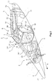
Figs 1a and 1b show a lateral view and an isometric view of a fairing element. -
Fig. 2 shows a partly transparent view from a different angle of view of the fairing element. -
Fig. 3 shows an oblique front view of the bridge element with components of a flap adjustment mechanism installed therein. -
Figures 1a and 1b show afairing element 2 for a flap adjustment mechanism (not shown in the diagrams) of an aircraft. Said fairingelement 2 comprises a shell-shapedfairing housing 4, which over a significant part along the direction of main extension (x) comprises a U-shaped profile that in the drawing plane is closed at the bottom and open at the top. Particularly preferably, the fairinghousing 4 comprises a fiber composite material, for example CFRP. In this manner it is possible to achieve an aerodynamically very favorable profile without incurring an excessively laborious or costly manufacturing effort. - The
fairing element 2, which comprises an adjustment mechanism and a flap driven by the aforesaid, is attachable, by way of afront section 3, to the underside of a wing. This front section is separated, by akink 7, from arear section 5 against which the driven flap may rest. - For the purpose of stiffening the fairing housing 4 a number of additional components are integrated in the fairing
housing 4, for example the approximately half-moon-shapedribs 6 in a region close to the leadingedge 11 of thefairing element 2, which components, by means ofholes 7 pointing towards the open side, may establish a redundant, secure mechanical connection with a main wing. Furthermore, as an example, afront frame element 8 and arear frame element 10 are shown with anaperture 12 for an articulated connection to a further fairing element adjoining saidrear frame element 10. - All of these additional elements are preferably made from the same material as the fairing
housing 4 itself. It suggests itself, in particular, to manufacture the fairinghousing 4, with thestiffening elements individual ribs 6 may be produced, pre-cured or pre-compacted from a resin-impregnated fiber fabric and may then be placed into a pre-compacted composite structure that will subsequently form the fairinghousing 4. The same applies to theframe elements - In order to further increase the rigidity, in particular the torsional rigidity on the direction of main extension (x), a
first cover panel 14 and asecond cover panel 16 are inserted as thrust plates on the open side of the fairinghousing 4, where they are attached. Attachment may also take place by mutual curing if thecover panels housing 4 adhesion to thecover panels - In particular in the case of manufacture from a metallic material the stiffening function of the
cover panels apertures fairing element 2. - The so-called
bridge element 24 is a central component that, for example, is arranged approximately in the middle of thefairing element 2, with thecover panels bridge element 24. Thebridge element 24 has a shape that matches the shape of the fairinghousing 4. This means that it has aU-shaped base area 26 that rests against aninternal surface 28 of the fairinghousing 4. Thebridge element 24 extends to the open side of the fairinghousing 4, where it comprises aplanar cover area 30 that closes thebridge element 24. Thebridge element 24 thus comprises a profile that is circumferential on the direction of main extension (x). - The
bridge element 24 may comprise a connectingregion 25 that corresponds to a connectingregion 27 in the fairinghousing 4. Merely as an example, an edge region on the open side of the fairinghousing 4 and of a region corresponding to it is shown as connectingregions housing 4 and on thebridge element 24 may be used as further connectingregions - The
bridge element 24 is preferably made from a metallic material; it may, for example, be milled from a solid aluminum block, as an alternative to this it may also be manufactured component by component and may be connected, with the use of welded connections or riveted connections, to form abridge element 24. As an alternative to this, a layer by layer design of abridge element 24 comprising a more complex shape would also be possible, for example by means of an ALM method or an SLM method in which a metal powder is put in place and cured, and subsequently the resulting component is treated, for example in a heat treatment process. - It is the object, by means of the
bridge element 24, to be able to provide a type of mechanical interface between the fairinghousing 4, a wing, and the adjustment mechanism. On thebridge element 24 an adjustment mechanism may be held, wherein, moreover, on itscover panel 30 attachment of thefairing element 2 to a wing takes place. - For example, in the
bridge element 24 an angle gear may be held which may be coupled, by way of a shaft feed-in 32, to a shaft of a central power control unit, (PCU). The angle gear may drive a spindle (not shown inFigures 1a and 1b ) that engages a spindle nut in order to carry out a defined movement. - For maintenance, component exchange and component installation,
several apertures housing 4, which apertures 34 and 36 are dimensioned in such a manner that a human hand and the components to be maintained may be fed through them. For example, therear aperture 34 has a diameter of more than 10 cm, in particular 13 to 16 cm or more. The same applies to themiddle aperture 36, which is furthermore aligned with an aperture in thebase area 26 of thebridge element 24. For closing theapertures - Between the
ribs 6 and thebridge element 24 on a lateral surface of the fairinghousing 4 there is anadditional aperture 37, in particular for the installation and maintenance of an actuator that may be arranged on the side of thebridge element 24, which side faces theribs 6. As an example, in the illustration theaperture 37 is rectangular with rounded corners. This may, for example, make it possible to insert into the fairinghousing 4 an actuator comprising a rectangular housing, and to attach said actuator in that location. In particular through the access opening 36, which is located beside the rectangular access opening 37, a hand may be inserted to support and guide the actuator. - For local reinforcement of the
apertures annular thickenings housing 4 so that the stress, which results in that location as a result of torsional forces or bending forces acting on the fairinghousing 4, may be reduced. Furthermore, the thickenings may prevent mechanical loads acting on the covers of the apertures. - In
Figure 2 thefairing element 2 is shown so as to be transparent in parts. This view shows anaperture 42 in thebridge element 24, whichaperture 42 is aligned with theaperture 36 of the fairinghousing 4. Furthermore, the illustration shows an overlap of anedge surface 44 of the second cover panel with anedge surface 46 of thebridge element 24. The same may be implemented in terms of thefirst cover panel 14. Moreover, saidfirst cover panel 14 extends above theframe element 8 and, for example, does not establish contact with saidframe element 8. Theribs 6, theframe element 8 and theframe element 10 form integral parts of the fairinghousing 4. - Lastly,
Figure 3 shows a view A, designated "A" inFigure 1a , with anadjustment mechanism 51 comprising anangle gear 48 that is integrated in thebridge element 24 and, by way of ashaft connection 32, may be coupled to a central flap drive. From the rotation of theshaft connection 32 theangle gear 48 may implement rotation of a threadedspindle 50 on which a threadednut 52 is arranged. The latter acts on alever 54 that is responsible for movement of a kinematic element coupled to it. Since the function of thefairing element 2 does not depend on the adjustment mechanism per se, no further details are shown in this context. - In summary, a particularly
advantageous fairing element 2 for an adjustment mechanism on a wing of an aircraft results, whichfairing element 2 is load-bearing, simple to manufacture and features light weight. The integration of a bridge element, to which the mechanical components are coupled, and to which also punctiform introductions of force are possible, introduces the resulting forces over a large area into the stiffened fairinghousing 4. - In addition, it should be pointed out that "comprising" does not exclude other elements or steps, and "a" or "one" does not exclude a plural number. Furthermore, it should be pointed out that characteristics which have been described with reference to one of the above exemplary embodiments may also be used in combination with other characteristics of other exemplary embodiments described above. Reference characters in the claims are not to be interpreted as limitations.
Claims (15)
- A load-bearing fairing element (2) for a flap adjustment mechanism (51) of an aircraft, comprising- a shell-shaped fairing housing (4) with an at least partly U-shaped profile with an open side, a closed side, and a direction of main extension (x),- at least one first cover panel (14) that along the direction of main extension (x) covers part of the open side, and- a load-bearing bridge element (24),
wherein the bridge element (24) is arranged in the fairing housing (4), with a base area (26) conforms so as to be flush against an internal surface (28) of the fairing housing (4) and extends towards the open side, and comprises an essentially planar cover area (30) that covers the base area (26) on the open side in order to produce a closed profile contour that is circumferential on the direction of main extension (x),
wherein the bridge element (24) comprises means for holding a shaft feed-in (32) of a central flap drive, and means for holding an adjustment mechanism (51) that is couplable to the shaft feed-in (32). - The fairing element (2) of claim 1,
wherein the fairing housing (4) is made from a fiber composite material and comprises at least one integral stiffening component (6, 8, 10). - The fairing element (2) of claim 1 or 2,
wherein the fairing housing (4) furthermore comprises at least one connection means (9) that is designed to establish a mechanical connection with a wing. - The fairing element (2) of claim 2 or 3,
wherein the fairing housing (4), in a region close to the leading edge (11) of the fairing element (2), comprises a multitude of ribs (6) that are spaced apart from each other, which ribs are arranged transversely to the direction of main extension (x). - The fairing element (2) of any one of the preceding claims,
wherein the fairing housing (4) on an internal surface comprises a load introduction region (29) in which the bridge element (24) is integrally connected to the fairing housing (4). - The fairing element (2) of claim 5,
wherein the load introduction region (29) is delimited in at least one direction along the direction of main extension (x) by means of at least one flat flange. - The fairing element (2) of any one of the preceding claims,
wherein the bridge element (24) comprises at least one connecting region (25) that corresponds to a connecting region (27) of the fairing housing (4), and the bridge element (24) is connected to the fairing housing (4) by means of positive-locking or non-positive-locking connecting elements at least in the connecting regions (25, 27). - The fairing element (2) of any one of the preceding claims,
wherein the bridge element (24) has been manufactured from a metallic material. - The fairing element (2) of any one of the preceding claims,
further comprising a second cover panel (16), arranged along the direction of main extension on an end of the bridge element (24), which end is opposite the first cover panel (14). - The fairing element (2) of any one of the preceding claims,
wherein at least one access opening (36, 37) is integrated in the fairing housing (4),
wherein the at least one access opening (36, 37) is dimensioned in such a manner that a human hand can reach through the at least one access opening (36, 37) into the interior of the fairing housing (4). - The fairing element (2) of claim 10,
wherein at least one of the at least one access opening (36, 37) in the fairing housing (4) is aligned with an access opening (42) in the bridge element (24). - The fairing element (2) of one of claims 10 and 11,
wherein on each of the two lateral surfaces the fairing element (2) comprises at least one access opening (36, 37). - The fairing element (2) of any one of claims 10 to 12,
wherein at least one of the at least one access opening (36, 37) comprises an annular thickening (38, 40) on the edge. - The fairing element (2) of any one of claims 10 to 13,
wherein the bridge element (24) comprises an annular thickening in a region in which at least one of the at least one access opening (36, 37) of the fairing housing (4) is situated. - An aircraft, comprising a wing and at least one flap arranged so as to be movable relative to said wing, further comprising at least one adjustment mechanism (51) that is arranged in a fairing element (2) of any one of claims 1 to 14, which fairing element is attached to the wing.
Applications Claiming Priority (1)
| Application Number | Priority Date | Filing Date | Title |
|---|---|---|---|
| DE102014106930.7A DE102014106930B4 (en) | 2014-05-16 | 2014-05-16 | Load-bearing fairing element for a flap adjustment mechanism and aircraft with such a fairing element |
Publications (2)
| Publication Number | Publication Date |
|---|---|
| EP2944564A1 true EP2944564A1 (en) | 2015-11-18 |
| EP2944564B1 EP2944564B1 (en) | 2018-10-03 |
Family
ID=53174921
Family Applications (1)
| Application Number | Title | Priority Date | Filing Date |
|---|---|---|---|
| EP15167559.2A Active EP2944564B1 (en) | 2014-05-16 | 2015-05-13 | Load-bearing fairing element for a flap adjustment mechanism and aircraft having such a fairing element |
Country Status (3)
| Country | Link |
|---|---|
| US (1) | US9926069B2 (en) |
| EP (1) | EP2944564B1 (en) |
| DE (1) | DE102014106930B4 (en) |
Cited By (1)
| Publication number | Priority date | Publication date | Assignee | Title |
|---|---|---|---|---|
| CN112413100A (en) * | 2020-12-01 | 2021-02-26 | 上海航天控制技术研究所 | Long-endurance high-speed aircraft rudder shaft liquid flow cooling method and structure |
Families Citing this family (4)
| Publication number | Priority date | Publication date | Assignee | Title |
|---|---|---|---|---|
| DE102018120250A1 (en) * | 2018-08-20 | 2020-02-20 | Airbus Operations Gmbh | Flap support for supporting a flap of a wing for an aircraft |
| USD913908S1 (en) * | 2020-01-16 | 2021-03-23 | Raisbeck Engineering, Inc. | Left wheel fairing |
| USD913907S1 (en) * | 2020-01-16 | 2021-03-23 | Raisbeck Engineering, Inc. | Cargo pod fairing |
| EP4269232B1 (en) * | 2022-04-28 | 2025-03-19 | Airbus Operations GmbH | Fairing attachment system for a wing of an aircraft, aircraft wing and method for mounting a fairing device |
Citations (7)
| Publication number | Priority date | Publication date | Assignee | Title |
|---|---|---|---|---|
| EP0303458A2 (en) * | 1987-08-11 | 1989-02-15 | British Aerospace Public Limited Company | Trailing edge flaps for aircraft wings |
| EP0356142A2 (en) * | 1988-08-17 | 1990-02-28 | British Aerospace Public Limited Company | Structural box beams |
| WO2003035469A1 (en) * | 2001-10-24 | 2003-05-01 | Fischer Advanced Composite Components Ag | Carrying or guiding device for aircraft components |
| WO2005021375A1 (en) * | 2003-08-25 | 2005-03-10 | Mt Aerospace Ag | Support structure for a retractable and extendable flap, and use of said structure |
| WO2008009988A2 (en) * | 2006-07-20 | 2008-01-24 | Airbus Uk Limited | Composite structure and method of manufacture |
| EP2048077A2 (en) * | 2007-10-10 | 2009-04-15 | EADS Deutschland GmbH | Lift flap support system |
| US20130087662A1 (en) * | 2011-10-07 | 2013-04-11 | Airbus Operations Limited | Flap support |
Family Cites Families (3)
| Publication number | Priority date | Publication date | Assignee | Title |
|---|---|---|---|---|
| DE4107556C1 (en) * | 1991-03-08 | 1992-05-14 | Deutsche Airbus Gmbh, 2000 Hamburg, De | |
| US6719870B2 (en) * | 2000-12-15 | 2004-04-13 | The Boeing Company | Fastenerless internal support for hollow structures |
| US6802170B2 (en) * | 2002-01-07 | 2004-10-12 | Kurt K. Davis | Box beam and method for fabricating same |
-
2014
- 2014-05-16 DE DE102014106930.7A patent/DE102014106930B4/en active Active
-
2015
- 2015-05-13 EP EP15167559.2A patent/EP2944564B1/en active Active
- 2015-05-15 US US14/713,089 patent/US9926069B2/en not_active Expired - Fee Related
Patent Citations (8)
| Publication number | Priority date | Publication date | Assignee | Title |
|---|---|---|---|---|
| EP0303458A2 (en) * | 1987-08-11 | 1989-02-15 | British Aerospace Public Limited Company | Trailing edge flaps for aircraft wings |
| EP0356142A2 (en) * | 1988-08-17 | 1990-02-28 | British Aerospace Public Limited Company | Structural box beams |
| WO2003035469A1 (en) * | 2001-10-24 | 2003-05-01 | Fischer Advanced Composite Components Ag | Carrying or guiding device for aircraft components |
| WO2005021375A1 (en) * | 2003-08-25 | 2005-03-10 | Mt Aerospace Ag | Support structure for a retractable and extendable flap, and use of said structure |
| WO2008009988A2 (en) * | 2006-07-20 | 2008-01-24 | Airbus Uk Limited | Composite structure and method of manufacture |
| EP2048077A2 (en) * | 2007-10-10 | 2009-04-15 | EADS Deutschland GmbH | Lift flap support system |
| DE102007048449A1 (en) | 2007-10-10 | 2009-04-23 | Eads Deutschland Gmbh | Lift flaps support system |
| US20130087662A1 (en) * | 2011-10-07 | 2013-04-11 | Airbus Operations Limited | Flap support |
Cited By (2)
| Publication number | Priority date | Publication date | Assignee | Title |
|---|---|---|---|---|
| CN112413100A (en) * | 2020-12-01 | 2021-02-26 | 上海航天控制技术研究所 | Long-endurance high-speed aircraft rudder shaft liquid flow cooling method and structure |
| CN112413100B (en) * | 2020-12-01 | 2022-07-01 | 上海航天控制技术研究所 | Long-endurance high-speed aircraft rudder shaft liquid flow cooling method and structure |
Also Published As
| Publication number | Publication date |
|---|---|
| DE102014106930B4 (en) | 2024-07-04 |
| US20170247104A2 (en) | 2017-08-31 |
| DE102014106930A1 (en) | 2015-11-19 |
| US20150329198A1 (en) | 2015-11-19 |
| US9926069B2 (en) | 2018-03-27 |
| EP2944564B1 (en) | 2018-10-03 |
Similar Documents
| Publication | Publication Date | Title |
|---|---|---|
| EP2944564B1 (en) | Load-bearing fairing element for a flap adjustment mechanism and aircraft having such a fairing element | |
| CN102971213B (en) | The control method of alighting gear frame cabin door and the hatch door of enforcement | |
| US6616101B2 (en) | Leading edge of supporting surfaces of aircraft | |
| EP2024227B1 (en) | Aircraft fuselage structure and method for producing it | |
| US6386481B1 (en) | Arrangement for fastening stringers to aircraft wing ribs | |
| US8172179B2 (en) | Aircraft wing box and manufacture thereof | |
| US20150329197A1 (en) | Flow Body With A Load Introduction Element Integrated Therein, Method For Manufacturing A Flow Body, And Aircraft With Such A Flow Body | |
| CN112776978B (en) | Leading edge slat for an aircraft, wing of an aircraft and method for an aircraft wing | |
| EP2589531B1 (en) | Internal structure of aircraft made of composite material | |
| EP2688799B1 (en) | Link mechanism for krueger flaps and method for loosening them | |
| JP6681049B2 (en) | Assembly method of aircraft control surface | |
| US20090127403A1 (en) | Lift flap carrier system | |
| US8226037B2 (en) | Aircraft door assembly, and aircraft fuselage comprising such an aircraft door assembly | |
| US20220194553A1 (en) | Modular aerostruktur assembly | |
| US12479569B2 (en) | Aircraft wing assembly including high lift device with an overlapped connection point | |
| US20080105786A1 (en) | Stringer for an aircraft wing and a method of reinforcing thereof | |
| US12006064B2 (en) | Manufacturing method of a control surface of an aircraft and aircraft control surface | |
| EP4378825B1 (en) | MOVABLE FLOW BODY WITH HYBRID LOAD INTRODUCTION RIBBON | |
| CN208325670U (en) | A kind of middle rear body joist assembly tooling |
Legal Events
| Date | Code | Title | Description |
|---|---|---|---|
| PUAI | Public reference made under article 153(3) epc to a published international application that has entered the european phase |
Free format text: ORIGINAL CODE: 0009012 |
|
| AK | Designated contracting states |
Kind code of ref document: A1 Designated state(s): AL AT BE BG CH CY CZ DE DK EE ES FI FR GB GR HR HU IE IS IT LI LT LU LV MC MK MT NL NO PL PT RO RS SE SI SK SM TR |
|
| AX | Request for extension of the european patent |
Extension state: BA ME |
|
| 17P | Request for examination filed |
Effective date: 20160517 |
|
| RBV | Designated contracting states (corrected) |
Designated state(s): AL AT BE BG CH CY CZ DE DK EE ES FI FR GB GR HR HU IE IS IT LI LT LU LV MC MK MT NL NO PL PT RO RS SE SI SK SM TR |
|
| GRAP | Despatch of communication of intention to grant a patent |
Free format text: ORIGINAL CODE: EPIDOSNIGR1 |
|
| STAA | Information on the status of an ep patent application or granted ep patent |
Free format text: STATUS: GRANT OF PATENT IS INTENDED |
|
| RIC1 | Information provided on ipc code assigned before grant |
Ipc: B64C 9/02 20060101ALI20180608BHEP Ipc: B64C 7/00 20060101AFI20180608BHEP Ipc: B64C 9/16 20060101ALI20180608BHEP |
|
| INTG | Intention to grant announced |
Effective date: 20180709 |
|
| GRAS | Grant fee paid |
Free format text: ORIGINAL CODE: EPIDOSNIGR3 |
|
| GRAA | (expected) grant |
Free format text: ORIGINAL CODE: 0009210 |
|
| STAA | Information on the status of an ep patent application or granted ep patent |
Free format text: STATUS: THE PATENT HAS BEEN GRANTED |
|
| AK | Designated contracting states |
Kind code of ref document: B1 Designated state(s): AL AT BE BG CH CY CZ DE DK EE ES FI FR GB GR HR HU IE IS IT LI LT LU LV MC MK MT NL NO PL PT RO RS SE SI SK SM TR |
|
| REG | Reference to a national code |
Ref country code: GB Ref legal event code: FG4D |
|
| REG | Reference to a national code |
Ref country code: CH Ref legal event code: EP Ref country code: AT Ref legal event code: REF Ref document number: 1048311 Country of ref document: AT Kind code of ref document: T Effective date: 20181015 |
|
| REG | Reference to a national code |
Ref country code: IE Ref legal event code: FG4D Ref country code: DE Ref legal event code: R096 Ref document number: 602015017363 Country of ref document: DE |
|
| REG | Reference to a national code |
Ref country code: NL Ref legal event code: MP Effective date: 20181003 |
|
| REG | Reference to a national code |
Ref country code: LT Ref legal event code: MG4D |
|
| PG25 | Lapsed in a contracting state [announced via postgrant information from national office to epo] |
Ref country code: NL Free format text: LAPSE BECAUSE OF FAILURE TO SUBMIT A TRANSLATION OF THE DESCRIPTION OR TO PAY THE FEE WITHIN THE PRESCRIBED TIME-LIMIT Effective date: 20181003 |
|
| PG25 | Lapsed in a contracting state [announced via postgrant information from national office to epo] |
Ref country code: FI Free format text: LAPSE BECAUSE OF FAILURE TO SUBMIT A TRANSLATION OF THE DESCRIPTION OR TO PAY THE FEE WITHIN THE PRESCRIBED TIME-LIMIT Effective date: 20181003 Ref country code: LT Free format text: LAPSE BECAUSE OF FAILURE TO SUBMIT A TRANSLATION OF THE DESCRIPTION OR TO PAY THE FEE WITHIN THE PRESCRIBED TIME-LIMIT Effective date: 20181003 Ref country code: PL Free format text: LAPSE BECAUSE OF FAILURE TO SUBMIT A TRANSLATION OF THE DESCRIPTION OR TO PAY THE FEE WITHIN THE PRESCRIBED TIME-LIMIT Effective date: 20181003 Ref country code: BG Free format text: LAPSE BECAUSE OF FAILURE TO SUBMIT A TRANSLATION OF THE DESCRIPTION OR TO PAY THE FEE WITHIN THE PRESCRIBED TIME-LIMIT Effective date: 20190103 Ref country code: CZ Free format text: LAPSE BECAUSE OF FAILURE TO SUBMIT A TRANSLATION OF THE DESCRIPTION OR TO PAY THE FEE WITHIN THE PRESCRIBED TIME-LIMIT Effective date: 20181003 Ref country code: IS Free format text: LAPSE BECAUSE OF FAILURE TO SUBMIT A TRANSLATION OF THE DESCRIPTION OR TO PAY THE FEE WITHIN THE PRESCRIBED TIME-LIMIT Effective date: 20190203 Ref country code: NO Free format text: LAPSE BECAUSE OF FAILURE TO SUBMIT A TRANSLATION OF THE DESCRIPTION OR TO PAY THE FEE WITHIN THE PRESCRIBED TIME-LIMIT Effective date: 20190103 Ref country code: ES Free format text: LAPSE BECAUSE OF FAILURE TO SUBMIT A TRANSLATION OF THE DESCRIPTION OR TO PAY THE FEE WITHIN THE PRESCRIBED TIME-LIMIT Effective date: 20181003 Ref country code: HR Free format text: LAPSE BECAUSE OF FAILURE TO SUBMIT A TRANSLATION OF THE DESCRIPTION OR TO PAY THE FEE WITHIN THE PRESCRIBED TIME-LIMIT Effective date: 20181003 Ref country code: LV Free format text: LAPSE BECAUSE OF FAILURE TO SUBMIT A TRANSLATION OF THE DESCRIPTION OR TO PAY THE FEE WITHIN THE PRESCRIBED TIME-LIMIT Effective date: 20181003 |
|
| PG25 | Lapsed in a contracting state [announced via postgrant information from national office to epo] |
Ref country code: AL Free format text: LAPSE BECAUSE OF FAILURE TO SUBMIT A TRANSLATION OF THE DESCRIPTION OR TO PAY THE FEE WITHIN THE PRESCRIBED TIME-LIMIT Effective date: 20181003 Ref country code: SE Free format text: LAPSE BECAUSE OF FAILURE TO SUBMIT A TRANSLATION OF THE DESCRIPTION OR TO PAY THE FEE WITHIN THE PRESCRIBED TIME-LIMIT Effective date: 20181003 Ref country code: RS Free format text: LAPSE BECAUSE OF FAILURE TO SUBMIT A TRANSLATION OF THE DESCRIPTION OR TO PAY THE FEE WITHIN THE PRESCRIBED TIME-LIMIT Effective date: 20181003 Ref country code: GR Free format text: LAPSE BECAUSE OF FAILURE TO SUBMIT A TRANSLATION OF THE DESCRIPTION OR TO PAY THE FEE WITHIN THE PRESCRIBED TIME-LIMIT Effective date: 20190104 Ref country code: PT Free format text: LAPSE BECAUSE OF FAILURE TO SUBMIT A TRANSLATION OF THE DESCRIPTION OR TO PAY THE FEE WITHIN THE PRESCRIBED TIME-LIMIT Effective date: 20190203 |
|
| REG | Reference to a national code |
Ref country code: DE Ref legal event code: R097 Ref document number: 602015017363 Country of ref document: DE |
|
| PG25 | Lapsed in a contracting state [announced via postgrant information from national office to epo] |
Ref country code: IT Free format text: LAPSE BECAUSE OF FAILURE TO SUBMIT A TRANSLATION OF THE DESCRIPTION OR TO PAY THE FEE WITHIN THE PRESCRIBED TIME-LIMIT Effective date: 20181003 Ref country code: DK Free format text: LAPSE BECAUSE OF FAILURE TO SUBMIT A TRANSLATION OF THE DESCRIPTION OR TO PAY THE FEE WITHIN THE PRESCRIBED TIME-LIMIT Effective date: 20181003 |
|
| PLBE | No opposition filed within time limit |
Free format text: ORIGINAL CODE: 0009261 |
|
| STAA | Information on the status of an ep patent application or granted ep patent |
Free format text: STATUS: NO OPPOSITION FILED WITHIN TIME LIMIT |
|
| PG25 | Lapsed in a contracting state [announced via postgrant information from national office to epo] |
Ref country code: EE Free format text: LAPSE BECAUSE OF FAILURE TO SUBMIT A TRANSLATION OF THE DESCRIPTION OR TO PAY THE FEE WITHIN THE PRESCRIBED TIME-LIMIT Effective date: 20181003 Ref country code: RO Free format text: LAPSE BECAUSE OF FAILURE TO SUBMIT A TRANSLATION OF THE DESCRIPTION OR TO PAY THE FEE WITHIN THE PRESCRIBED TIME-LIMIT Effective date: 20181003 Ref country code: SK Free format text: LAPSE BECAUSE OF FAILURE TO SUBMIT A TRANSLATION OF THE DESCRIPTION OR TO PAY THE FEE WITHIN THE PRESCRIBED TIME-LIMIT Effective date: 20181003 Ref country code: SM Free format text: LAPSE BECAUSE OF FAILURE TO SUBMIT A TRANSLATION OF THE DESCRIPTION OR TO PAY THE FEE WITHIN THE PRESCRIBED TIME-LIMIT Effective date: 20181003 |
|
| 26N | No opposition filed |
Effective date: 20190704 |
|
| PG25 | Lapsed in a contracting state [announced via postgrant information from national office to epo] |
Ref country code: SI Free format text: LAPSE BECAUSE OF FAILURE TO SUBMIT A TRANSLATION OF THE DESCRIPTION OR TO PAY THE FEE WITHIN THE PRESCRIBED TIME-LIMIT Effective date: 20181003 |
|
| REG | Reference to a national code |
Ref country code: AT Ref legal event code: UEP Ref document number: 1048311 Country of ref document: AT Kind code of ref document: T Effective date: 20181003 |
|
| REG | Reference to a national code |
Ref country code: CH Ref legal event code: PL |
|
| PG25 | Lapsed in a contracting state [announced via postgrant information from national office to epo] |
Ref country code: LI Free format text: LAPSE BECAUSE OF NON-PAYMENT OF DUE FEES Effective date: 20190531 Ref country code: CH Free format text: LAPSE BECAUSE OF NON-PAYMENT OF DUE FEES Effective date: 20190531 Ref country code: MC Free format text: LAPSE BECAUSE OF FAILURE TO SUBMIT A TRANSLATION OF THE DESCRIPTION OR TO PAY THE FEE WITHIN THE PRESCRIBED TIME-LIMIT Effective date: 20181003 |
|
| REG | Reference to a national code |
Ref country code: BE Ref legal event code: MM Effective date: 20190531 |
|
| PG25 | Lapsed in a contracting state [announced via postgrant information from national office to epo] |
Ref country code: LU Free format text: LAPSE BECAUSE OF NON-PAYMENT OF DUE FEES Effective date: 20190513 |
|
| PG25 | Lapsed in a contracting state [announced via postgrant information from national office to epo] |
Ref country code: TR Free format text: LAPSE BECAUSE OF FAILURE TO SUBMIT A TRANSLATION OF THE DESCRIPTION OR TO PAY THE FEE WITHIN THE PRESCRIBED TIME-LIMIT Effective date: 20181003 |
|
| PG25 | Lapsed in a contracting state [announced via postgrant information from national office to epo] |
Ref country code: IE Free format text: LAPSE BECAUSE OF NON-PAYMENT OF DUE FEES Effective date: 20190513 |
|
| PG25 | Lapsed in a contracting state [announced via postgrant information from national office to epo] |
Ref country code: BE Free format text: LAPSE BECAUSE OF NON-PAYMENT OF DUE FEES Effective date: 20190531 |
|
| PG25 | Lapsed in a contracting state [announced via postgrant information from national office to epo] |
Ref country code: FR Free format text: LAPSE BECAUSE OF NON-PAYMENT OF DUE FEES Effective date: 20190531 |
|
| PG25 | Lapsed in a contracting state [announced via postgrant information from national office to epo] |
Ref country code: CY Free format text: LAPSE BECAUSE OF FAILURE TO SUBMIT A TRANSLATION OF THE DESCRIPTION OR TO PAY THE FEE WITHIN THE PRESCRIBED TIME-LIMIT Effective date: 20181003 |
|
| PG25 | Lapsed in a contracting state [announced via postgrant information from national office to epo] |
Ref country code: HU Free format text: LAPSE BECAUSE OF FAILURE TO SUBMIT A TRANSLATION OF THE DESCRIPTION OR TO PAY THE FEE WITHIN THE PRESCRIBED TIME-LIMIT; INVALID AB INITIO Effective date: 20150513 Ref country code: MT Free format text: LAPSE BECAUSE OF FAILURE TO SUBMIT A TRANSLATION OF THE DESCRIPTION OR TO PAY THE FEE WITHIN THE PRESCRIBED TIME-LIMIT Effective date: 20181003 |
|
| PG25 | Lapsed in a contracting state [announced via postgrant information from national office to epo] |
Ref country code: MK Free format text: LAPSE BECAUSE OF FAILURE TO SUBMIT A TRANSLATION OF THE DESCRIPTION OR TO PAY THE FEE WITHIN THE PRESCRIBED TIME-LIMIT Effective date: 20181003 |
|
| PGFP | Annual fee paid to national office [announced via postgrant information from national office to epo] |
Ref country code: DE Payment date: 20250521 Year of fee payment: 11 |
|
| PGFP | Annual fee paid to national office [announced via postgrant information from national office to epo] |
Ref country code: GB Payment date: 20250521 Year of fee payment: 11 |
|
| PGFP | Annual fee paid to national office [announced via postgrant information from national office to epo] |
Ref country code: AT Payment date: 20250522 Year of fee payment: 11 |