EP2944492A1 - A glass run seal for a movable pane in a vehicle window aperture. - Google Patents
A glass run seal for a movable pane in a vehicle window aperture. Download PDFInfo
- Publication number
- EP2944492A1 EP2944492A1 EP14168276.5A EP14168276A EP2944492A1 EP 2944492 A1 EP2944492 A1 EP 2944492A1 EP 14168276 A EP14168276 A EP 14168276A EP 2944492 A1 EP2944492 A1 EP 2944492A1
- Authority
- EP
- European Patent Office
- Prior art keywords
- glass run
- seal assembly
- reinforcement
- leg
- legs
- Prior art date
- Legal status (The legal status is an assumption and is not a legal conclusion. Google has not performed a legal analysis and makes no representation as to the accuracy of the status listed.)
- Granted
Links
Images


Classifications
-
- B—PERFORMING OPERATIONS; TRANSPORTING
- B60—VEHICLES IN GENERAL
- B60J—WINDOWS, WINDSCREENS, NON-FIXED ROOFS, DOORS, OR SIMILAR DEVICES FOR VEHICLES; REMOVABLE EXTERNAL PROTECTIVE COVERINGS SPECIALLY ADAPTED FOR VEHICLES
- B60J10/00—Sealing arrangements
- B60J10/80—Sealing arrangements specially adapted for opening panels, e.g. doors
- B60J10/86—Sealing arrangements specially adapted for opening panels, e.g. doors arranged on the opening panel
- B60J10/88—Sealing arrangements specially adapted for opening panels, e.g. doors arranged on the opening panel mounted on, or integral with, the glass-run seals
-
- B—PERFORMING OPERATIONS; TRANSPORTING
- B60—VEHICLES IN GENERAL
- B60J—WINDOWS, WINDSCREENS, NON-FIXED ROOFS, DOORS, OR SIMILAR DEVICES FOR VEHICLES; REMOVABLE EXTERNAL PROTECTIVE COVERINGS SPECIALLY ADAPTED FOR VEHICLES
- B60J10/00—Sealing arrangements
- B60J10/15—Sealing arrangements characterised by the material
- B60J10/16—Sealing arrangements characterised by the material consisting of two or more plastic materials having different physical or chemical properties
-
- B—PERFORMING OPERATIONS; TRANSPORTING
- B60—VEHICLES IN GENERAL
- B60J—WINDOWS, WINDSCREENS, NON-FIXED ROOFS, DOORS, OR SIMILAR DEVICES FOR VEHICLES; REMOVABLE EXTERNAL PROTECTIVE COVERINGS SPECIALLY ADAPTED FOR VEHICLES
- B60J10/00—Sealing arrangements
- B60J10/15—Sealing arrangements characterised by the material
- B60J10/18—Sealing arrangements characterised by the material provided with reinforcements or inserts
-
- B—PERFORMING OPERATIONS; TRANSPORTING
- B60—VEHICLES IN GENERAL
- B60J—WINDOWS, WINDSCREENS, NON-FIXED ROOFS, DOORS, OR SIMILAR DEVICES FOR VEHICLES; REMOVABLE EXTERNAL PROTECTIVE COVERINGS SPECIALLY ADAPTED FOR VEHICLES
- B60J10/00—Sealing arrangements
- B60J10/20—Sealing arrangements characterised by the shape
- B60J10/26—Sealing arrangements characterised by the shape characterised by the surface shape
- B60J10/265—Sealing arrangements characterised by the shape characterised by the surface shape the surface being primarily decorative
-
- B—PERFORMING OPERATIONS; TRANSPORTING
- B60—VEHICLES IN GENERAL
- B60J—WINDOWS, WINDSCREENS, NON-FIXED ROOFS, DOORS, OR SIMILAR DEVICES FOR VEHICLES; REMOVABLE EXTERNAL PROTECTIVE COVERINGS SPECIALLY ADAPTED FOR VEHICLES
- B60J10/00—Sealing arrangements
- B60J10/30—Sealing arrangements characterised by the fastening means
Definitions
- the invention relates to a glass run seal assembly for automotive vehicles. More particularly, the present invention relates to a glass run seal assembly comprising extruded thermoplastic polymeric structural materials, thermoplastic polymer and an integral reinforcement.
- Vehicle glass run seals are used in automotive vehicles to support a window pane while allowing the window pane to move between an open and a closed position.
- the glass run seal guides and supports the window pane and forms a seal between the window pane and the vehicle door or body structure.
- the glass run seal protects the passenger compartment from the elements, holds the window pane in position to prevent movement other than in an intended translational direction while allowing window pane translational movement without significant resistance.
- a glass run seal which can be easily installed during manufacture of the vehicle to extend along the sides and top of the window opening while also meeting the requirements for support and guiding as described above.
- a glass run seal design has a metallic core with a generally S-shaped cross-section which is covered by suitable elastomeric material. The S-shape provides one channel facing in a first direction for clamping attachment to a door flange for attaching the channel and a second channel facing in a second direction for guiding and supporting a glass pane.
- a problem with an S-shaped metallic core is that the S-shape is so stiff that it is difficult to bend to follow the curvature along the upper portion (header) of the window opening.
- a further problem is that the elastomeric material may wrinkle locally when bent to the required curvature.
- GB 2 093 407 describes a method of forming a permanent curve in a reinforced strip of plastics material, wherein an L-shaped core of a thermoplastic resin forms a reinforcing strip.
- the method comprises the steps of heating a section of the strip until pliable, stretching the section round a curved forming jig, and maintaining the section under tension round the forming jig until the section has cooled to a non-pliable state.
- a problem with this solution is that it requires further working of the strip after the extrusion process. This involves additional heating, stretching and bending of a local portion of the strip, which can cause localized changes in material properties and dimensional variations for the strip.
- the object of the invention is to provide an improved glass run seal and a manufacturing method which solves the above problems relating to resistance to bending and wrinkling of a glass run seal.
- the invention relates to a glass run seal assembly for a movable pane in a vehicle window aperture, in particular to a glass run seal assembly having at least one curved section.
- the glass run seal assembly can typically be arranged in a vehicle window aperture along a vehicle front door, adjacent a front A-pillar, along a vehicle rear door, adjacent a rear C-pillar in a sedan or saloon type vehicle, or extend along the window apertures of both a front and rear door.
- the glass run seal assembly comprises a first portion having a generally U-shaped cross section defining a glass run channel.
- the U-shaped glass run channel has first and second legs with edges joined by a base web, wherein at least the legs of the first portion comprises elastomeric extrusions bonded to the base web.
- the base web comprises a thermoplastic polymeric structural material.
- the first and second legs of the glass run channel are preferably each provided with one or more sealing lips, extending from the respective leg into the open U-shaped glass run channel along the longitudinal extension of the glass run seal assembly. The sealing lips are contacted and/or displaced by a pane moving into the glass run channel to close the window aperture.
- the glass run seal assembly further comprises a second portion having a generally U-shaped cross section, defining an attachment channel.
- the attachment channel has a first and a second leg with edges joined by a base web.
- the legs and the base web of the second portion comprise a thermoplastic polymeric structural material.
- the first leg of the second portion has an edge remote from its base web, which edge is integral with the base web of the first portion.
- the second leg of the second portion forming part of the attachment channel, comprises a reinforcement extending within the second leg in the longitudinal extension thereof and providing structural support for at least one curved section of the glass run seal assembly.
- the second leg of the second portion with the reinforcement has a lower coefficient of thermal expansion than the first leg of the second portion.
- the reinforcement is arranged so that a cross-section through the reinforcement has a major extension in a plane located at right angles to the main direction of the U-shaped opening into the glass run channel. Consequently, the reinforcement has a major extension in a plane located at right angles to the plane of the portion of a pane to be located in the glass run channel at that cross-section.
- the main direction of the U-shaped opening into the glass run channel will correspond with a line at right angles to a tangent to the curved glass run seal assembly at each point along a curved section of the assembly.
- a central axis between the first and second legs in a cross-section of the U-shaped opening that extends into and forms the glass run channel can be arranged to intersect the reinforcement integrated in the second leg of the second portion.
- the reinforcement preferably, but not necessarily, comprises a metal core.
- the metal core comprises at least one metal strip.
- a cross-section of the strip can have a width within the range 2-8 mm and a thickness within the range 0.1-1 mm and can comprise a suitable metal such as copper, aluminium or an aluminium alloy.
- the reinforcement can comprise two or more metal strips arranged side by side. The dimensions of multiple strips are chosen to provide the same mechanical properties as for a single strip.
- the reinforcement can comprise multiple parallel, intertwined or woven metal wires or threads/fibres of a suitable plastic material, such as glass fibre, to provide the second leg of the second portion with the desired properties relating to the coefficient of thermal expansion.
- the legs and the base web of the second portion and the base web of the first portion comprise a thermoplastic polymeric structural material.
- a suitable material for this purpose is a structural grade polypropylene (PP).
- PP polypropylene
- the reinforcement should have an outer surface having suitable properties for achieving good adhesion with the thermoplastic polymeric structural material.
- adhesive properties can be provided by the material making up the reinforcement, a suitable surface treatment thereof, or by a coating applied to the material.
- the legs of the first portion comprises elastomeric extrusions co-extruded with and bonded to their base web to form a glass run channel.
- the first and second legs of the first portion comprises thermoplastic vulcanizates (TPV), also termed elastomeric alloys (EA) or dynamically vulcanized thermoplastic elastomers (TPE).
- TSV thermoplastic vulcanizates
- EA elastomeric alloys
- TPE dynamically vulcanized thermoplastic elastomers
- the first and second legs first of the first portion and the sealing lips are co-extruded with and bonded to the legs and comprises the same or similar materials.
- sealing lips can comprise a softer grade of material to allow them to conform to the shape of the movable pane. This will be described in further detail below.
- a reinforcement as described above is arranged to extend within at least one longitudinal section of the second leg where the glass run seal assembly has a curvature.
- at least one reinforcement is arranged to extend within the second leg in the longitudinal extension thereof to provide structural support for a corresponding curved section of the glass run seal assembly.
- the reinforcement is not arranged throughout the entire length of the glass run assembly.
- a reinforcement is only required adjacent curved sections of the assembly where it is desired to prevent bulges or wrinkles along a curved section of the glass run seal assembly.
- the invention further relates to a method for manufacturing a glass run seal assembly.
- the method involves performing the steps of:
- the method can further involve inserting the reinforcement so that a cross-section through the reinforcement has a major extension in a plane located at right angles to the main direction of the U-shaped opening into the glass run channel.
- insertion of the reinforcement can be performed so that the central axis of, or plane through, the U-shaped opening into the glass run channel is arranged to intersect the reinforcement.
- the method preferably involves using a reinforcement comprising at least one metal strip.
- a reinforcement comprising at least one metal strip.
- Alternative types of reinforcements and suitable materials have been listed above.
- the reinforcement is inserted into the second leg of the second portion at predetermined locations during extrusion of the glass run seal assembly.
- a reinforcement is arranged to extend within at least one longitudinal section of the second leg where the glass run seal assembly will require a curvature following the shape of a vehicle window aperture.
- the reinforcing insert is located within a section of the glass run seal assembly comprising a thermoplastic polymeric structural material, such as structural polypropylene (PP).
- PP structural polypropylene
- the glass run seal assembly is hot and malleable after the extrusion process. During cooling the reinforcement prevents the thermoplastic polymeric structural material in the second leg of the second portion from shrinking.
- thermoplastic polymeric structural material in the first leg of the second portion and the elastomeric material are allowed to shrink during cooling.
- the glass run seal assembly will bend to form a curvature without wrinkles.
- the glass run seal assembly will bend in a plane located at right angles to the major extension of a cross-section through the reinforcement.
- the invention relates to a glass run seal assembly comprising a metal insert, such as an aluminium strip, that prevents the assembly from wrinkling during cooling and subsequent mounting onto a curved section the window opening of a vehicle door.
- a metal insert such as an aluminium strip
- the above method describes the basic structural sections of a glass run seal assembly according to the invention, which sections comprise an attachment channel with a reinforcement and a glass run channel.
- the extrusion process can involve additional component parts being co-extruded with their respective basic structural section.
- the a glass run channel can be provided with sealing lips extending into the generally U-shaped cross section, in order to contact and seal a portion along the upper part of a glass pane.
- the attachment channel can be provided with sealing lips extending away from its generally U-shaped cross section, in order to contact the vehicle chassis and seal a gap between an upper portion of the door and a corresponding section forming the upper portion of a door opening.
- Sealing lips of this type can be made from an elastomeric material of the same type used for the first and second legs for the first portion of the glass run channel. As the sealing lips need to be able to be deformed to conform to cooperating surfaces, the elastomeric material used is preferably a softer grade than used for the glass run channel.
- An optional metal trim 310 having the same curvature as the glass run seal assembly can be arranged to cover at least a part of the outer surfaces of the first and second portions 302, 304.
- the metal trim 310 is T-shaped, wherein its stem is retained in a recess between the first and second portions 302, 304.
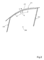
- FIG 4 shows a cross-section A-A (see Figure 2 ) through a glass run seal assembly 401 as schematically shown in Figures 2 and 3 .
- the glass run seal assembly 401 comprises a first portion 410 having a generally U-shaped cross section defining a glass run channel 410.
- the U-shaped glass run channel 410 has first and second legs 411, 412 with edges joined by a first base web 413, wherein the first and second legs 411, 412 of the first portion 410 comprises an extruded elastomeric material bonded to the base web 413, which base web comprises an extruded thermoplastic polymeric structural material.
- the first and second legs 411, 412 of the glass run channel 410 are each provided with sealing lips 414, 415, 416, 417, extending from the respective leg into the open U-shaped glass run channel 410 along the longitudinal extension of the glass run seal assembly 401.
- the sealing lips 414, 415, 416, 417 comprise an extruded elastomeric material bonded to their respective first and second legs 411, 412.
- the elastomeric material of the sealing lips 414, 415, 416, 417 is relatively softer that the elastomeric material of the first and second legs 411, 412.
- the first leg 411 forms an inner part of the glass run channel 410 and the second leg 412 forms an outer part of the glass run channel 410.
- the inner, first leg 411 comprises a first and a second sealing lip 414, 415 extending upwards at an angle into the U-shaped channel and are arranged to contact and seal against the inner surface of a pane located in the glass run channel 410.
- the first leg 411 further comprises an upper sealing lips 416 extending into the U-shaped channel substantially at right angles to the first leg 411.
- the upper sealing lip 416 is arranged to contact and seal against the upper edge of a pane located in the glass run channel 410.
- the outer, second leg 412 comprises a sealing lip 417 extending upwards at an angle into the U-shaped channel opposite the second sealing lip 415 of the first leg 411.
- the sealing lip 417 is arranged to contact and seal against the outer surface of a pane located in the glass run channel 410.
- the sealing lips 414, 415, 416, 417 are contacted and/or displaced by a pane 303 ( Figure 3 ) moving into the glass run channel 410 to close the window aperture 105 ( Figure 1 ).
- the glass run seal assembly 401 further comprises a second portion 420 having a generally U-shaped cross section, defining an attachment channel 420.
- the attachment channel 420 has a first and a second leg 421, 422 with edges joined by a second base web 423.
- the legs 421, 422 and the base web 423 of the attachment channel 420 comprise an extruded thermoplastic polymeric structural material.
- the first leg 421 of the attachment channel 420 has an edge 424 remote from its base web 423, which edge 424 is bonded to and integral with the base web 413 of the glass run channel 410. In this way, the glass run channel 410 and the attachment channel 420 are connected to form a glass run seal assembly.
- the base web 423 of the attachment channel 420 forms an outer surface extending substantially flush with the second leg 412 of the glass run channel 410.
- the first leg 421 extends inwards, away from the outer surfaces of the attachment channel 420 and the glass run channel 410 towards the base web 413 of the glass run channel 410.
- the second leg 422 forms an upper part of the attachment channel 420 and extends inwards substantially parallel to a corresponding portion of a door opening in the chassis (not shown).
- the upper, second leg 422 comprises a first and a second sealing lip 425, 426 extending upwards away from the U-shaped attachment channel 420.
- the first and second sealing lips 425, 426 are arranged to contact and seal against the door opening above the attachment channel 420.
- the second leg 422 of the attachment channel 420 comprises a reinforcement 430 extending within the second leg 422 in the longitudinal extension thereof.
- the reinforcement 430 provides structural support a locally curved section 431 (see Figure 2 ) of the glass run seal assembly.
- the second leg 422 of the attachment channel 420 with the reinforcement 430 has a lower coefficient of thermal expansion than the first leg 421 of the attachment channel 420.
- a first plane X 1 is located at the central axis of, and in the main direction of, the U-shaped opening 418 into the glass run channel 410.
- a second plane X 2 is located at the central axis of, and in the main direction of, the U-shaped opening 428 into the attachment channel 420.
- the reinforcement 430 is arranged so that a cross-section (section A-A; Figure 2 ) through the reinforcement 430 has a major extension in a third plane X 3 located at right angles to the first plane X 1 in the main direction of the U-shaped opening 418 into the glass run channel 410. Consequently, the reinforcement 430 has a major extension in a plane X 3 located at right angles to the plane of an upper portion of a pane (not shown) to be located in the opening 418 of the glass run channel 410 at that cross-section.
- the main direction of the U-shaped opening 418 into the glass run channel will coincide with a line R at right angles to a tangent T to the glass run seal assembly at each point along a curved section of the assembly (shown for section A-A in Figure 2 ).
- the plane X 3 through the major extension of the reinforcement 430 is parallel to the central plane X 2 into the opening 428 of the attachment channel 420.
- the first plane X 1 of the U-shaped opening 418 extending into the glass run channel 410 is also arranged to intersect the reinforcement 430 in the second leg 422 of the attachment channel 420. This arrangement of the reinforcement 430 allows the glass run seal assembly 401 to form a curve in a plane at right angles to the major extension of the reinforcement 430.
- the reinforcement 430 preferably, but not necessarily, comprises a metal core.
- the metal core comprises at least one metal strip.
- a cross-section of the strip can have a major extension, or width, within the range 2-8 mm and a minor extension, or thickness, within the range 0.1-1 mm and comprises a metal such as copper, aluminium or an aluminium alloy.
- the reinforcement can comprise two or more metal strips arranged side by side. The dimensions of multiple strips are chosen to provide the same mechanical properties as for a single strip.
- the reinforcement can comprise multiple parallel, intertwined or woven metal wires or threads/fibres of a suitable plastic material, such as glass fibre.
- the reinforcement has major extension, or width, and a minor extension, or thickness, in order to provide the second leg of the attachment channel with the desired properties relating to the coefficient of thermal expansion.
- a reinforcement 430 as described above is arranged to extend within at least one longitudinal section of the attachment channel 420 where the glass run seal assembly 401 has a curvature. As indicated above, at least one reinforcement 430 is arranged to extend within the second leg 422 of the attachment channel 420 in the longitudinal extension thereof to provide structural support for a corresponding curved section of the glass run seal assembly 401. Hence, the reinforcement is not arranged throughout the entire length of the glass run assembly. A reinforcement 430 is only required adjacent a length L of a curved section of the assembly 401, as shown in Figure 2 , where it is desired to prevent bulges or wrinkles along a curved section of the glass run seal assembly 401.
- the first and second legs 421, 422 and the base web 423 of the attachment channel 420 and the base web 413 of the glass run channel 410 comprise a thermoplastic polymeric structural material.
- a suitable material for this purpose is a structural grade polypropylene (PP).
- PP polypropylene
- the reinforcement 430 should have an outer surface having suitable properties for achieving good adhesion with the thermoplastic polymeric structural material.
- adhesive properties can be provided by the material making up the reinforcement itself, a suitable surface treatment thereof, or by a coating applied to the material.
- the first and second legs 411, 412 of the glass run channel 410 comprises elastomeric extrusions co-extruded with and bonded to their base web 413 to form a U-shaped glass run channel 410.
- the first and second legs 411, 412 of the glass run channel 410 comprises thermoplastic vulcanizates (TPV), also termed elastomeric alloys (EA) or dynamically vulcanized thermoplastic elastomers (TPE).
- TSV thermoplastic vulcanizates
- EA elastomeric alloys
- TPE dynamically vulcanized thermoplastic elastomers
- the first and second legs 411, 412 of the glass run channel 410 and their sealing lips 414, 415, 416, 417 are co-extruded and bonded to each other and comprises the same or similar materials.
- first and second legs 421, 422 of the attachment channel 420 and their sealing lips 425, 426 are co-extruded and bonded to each other.
- the sealing lips 414, 415, 416, 417, 425, 426 comprise a softer grade of material to allow them to conform to the shape of the movable pane or other contacting portions.
- the attachment channel 420 is formed of a polymeric material, and preferably a polymeric material having sufficient rigidity to perform the intended functions.
- a material that has been found suitable is a structural grade polypropylene. It is understood that comparably rigid thermoset materials can be employed. However, use of thermoset materials requires additional processing steps for recycling of the thermoset materials. In contrast, thermoplastic materials can be readily re-melted and reconfigured into subsequent products.
- the attachment channel 420 can be formed from a number of alternative plastic materials, for example, thermoplastics and thermoplastic elastomers (TPE).
- TPE thermoplastic elastomers
- TPE thermoplastic elastomers
- TPE thermoplastic elastomers
- TPE thermoplastic elastomers
- TPE thermoplastic elastomers
- TPE thermoplastic elastomers
- TPE hard and soft grades of plastic
- TPE are commercially available in several different brands and types. Each type can be obtained in different grades having different properties such as hardness, tensile strength, compression, elongation, thermal stability and colorability. Selection of the appropriate TPE for a particular application depends on a suitable combination for such properties.
- Types of TPE that are particularly useful are styrenic block co-polymers, rubber polyolefin blends, elastomeric alloys, thermoplastic alloys, thermoplastic elastomeric alloys, thermoplastic isomers, thermoplastic polyurethanes, polyvinyl chlorides and blends thereof.
- Polyvinyl chloride (PVC) based TPE:s are also suitable for window seals and are available in different grades and blends with other TPE:s and rubbers.
- Thermoplastic vulcanizates (TPV) with a relatively softer grade can be extruded to make profiles and seals.
- Thermoplastic vulcanizates comprises thermoplastic matrices, preferably crystalline, through which thermoset elastomers are generally uniformly distributed. Examples of thermoplastic vulcanizates include ethylene-propylene monomer rubber and ethylene-propylene-diene monomer rubber thermoset materials distributed in a crystalline polypropylene matrix.
- TPV polytyrene® thermoplastic rubber which is manufactured by Advanced Elastomer Systems and is a mixture of crosslinked EPDM particles in a crystalline polypropylene matrix. These materials have found utility in many applications which previously used vulcanized rubber, e.g., hoses, gaskets, and the like.
- Commercial TPV:s are typically based on vulcanized rubbers in which a phenolic resin or sulfur cure system is used to vulcanize, that is to crosslink, a diene (or more generally, a polyene) copolymer rubber by way of dynamic vulcanization, that is crosslinking while mixing (typically vigorously), in a thermoplastic matrix.
- TPV typically include a rubber component, a thermoplastic component, additive oil and other ingredients such as curing additives and the like.
- a variety of properties of TPVs are considered to be important, including but not limited to rebound, tensile strength and elongation, as well as varying degrees of softness or hardness.
- the glass contacting sealing lips of the header glass run channel can include a low friction surface which may be comprised of any suitable low friction material such as silicone, polyurethane, low friction flocking, or polypropylene.
- Figure 5 shows a schematic diagram for a method of manufacturing a glass run seal assembly according to the invention.
- the method involves performing a number of process steps in sequence once the process is started 500.
- a first step 501 involves extruding an elastomeric material forming individual first and second legs 411, 412 for a first portion 410 intended to form a glass run channel 410.
- the first step 501 involves simultaneous extrusion of a thermoplastic material forming a second portion 420 having a generally U-shaped cross section defining an attachment channel 420, the second portion 420 having first and second legs 421, 422 with edges joined by a base web 423, and a further base web 413 bonding with the extruded elastomeric material of the first and second legs 411, 412 of the first portion 410 to form a generally U-shaped cross section defining the glass run channel 410, the further base web 413 being integral with an edge 424 of the first leg 421 of the second portion 410.
- a second step 502 is performed during the simultaneous co-extrusion of the glass run channel 410 and the attachment channel 420.
- the second step 502 involves inserting a reinforcement 430 into the second leg 422 of the second portion 420 in at least one predetermined section L ( Figure 2 ) during extrusion of the thermoplastic material, wherein the co-extruded materials form a glass run seal assembly 401.
- a third step 503 is performed after the first and second steps 501, 502.
- the third step 503 involves cooling the extruded glass run seal assembly 401 and allowing the first leg 421 of the second portion 420 and the extruded first and second legs 411, 412 of the first portion 410 to shrink in the longitudinal direction relative to the reinforced second leg 422 of the second portion 420.
- the section L ( Figure 2 ) of the second leg 422 of the second portion 420 comprising the reinforcement 430 has a lower coefficient of thermal expansion than the remaining a glass run seal assembly 401, the glass run seal assembly 401 will bend during cooling to assume predetermined curvature. Once the glass run seal assembly 401 has cooled to ambient temperature, the process ends 504.
- the method involves inserting the reinforcement 430 so that a cross-section through the reinforcement 430 has a major extension in a plane X 3 located at right angles to a first plane X 1 in the main direction of the U-shaped opening 418 into the glass run channel 410.
- insertion of the reinforcement 430 can be performed so that the first plane X 1 of the U-shaped opening 418 into the glass run channel 410 is arranged to intersect the reinforcement 430.
- the method preferably involves using a reinforcement comprising at least one metal strip.
- a reinforcement comprising at least one metal strip.
- Alternative types of reinforcements to be inserted during the second step 502 have been listed above.
- the reinforcement 430 is inserted into the second leg 422 of the second portion 420 at predetermined locations during extrusion of the glass run seal assembly 401.
- the reinforcement 430 is arranged to extend within at least one longitudinal section L of the second leg 422 where the glass run seal assembly 401 will require a curvature following the shape of a vehicle window aperture ( Figure 1 & 2 ).
- the reinforcing insert 430 is located within a section L of the glass run seal assembly 401 comprising a thermoplastic polymeric structural material, such as structural polypropylene (PP).
- PP structural polypropylene
- the reinforcement/insert 430 prevents the thermoplastic polymeric structural material in the second leg 422 of the second portion from shrinking.
- the thermoplastic polymeric structural material in the first leg 421 of the second portion 420 and the elastomeric material in the remaining sections and seals are allowed to shrink during cooling.
- the glass run seal assembly 401 will bend to form a curvature without wrinkles.
- the glass run seal assembly 401 will bend in a plane XY located at right angles to a plane X 3 in the major extension of a cross-section through the reinforcement 430.
- the invention relates to a glass run seal assembly 401 comprising a metal insert, such as an aluminium strip, that prevents the assembly from wrinkling during cooling and subsequent mounting onto a curved section the window opening of a vehicle door.
- a metal insert such as an aluminium strip
- the a glass run channel 410 can be provided with sealing lips 414, 415, 416, 417 extending into the generally U-shaped cross section, in order to contact and seal a portion along the upper part of a glass pane.
- the attachment channel 420 can be provided with sealing lips 425, 426 extending away from its generally U-shaped cross section, in order to contact the vehicle chassis and seal a gap between an upper portion of the door and a corresponding section forming the upper portion of a door opening. Sealing lips of this type can be made from an elastomeric material of the same type used for the first and second legs for the first portion of the glass run channel.
- the elastomeric material used is preferably a softer grade than used for the glass run channel.
- the invention is not limited to the above examples, but may be varied within the scope of the invention.
- the relative positions of the glass run channel 410 and the attachment channel 420, as well as the location and number of sealing lips, is not limited to the examples given in the text above.
Landscapes
- Engineering & Computer Science (AREA)
- Mechanical Engineering (AREA)
- Seal Device For Vehicle (AREA)
Abstract
Description
- The invention relates to a glass run seal assembly for automotive vehicles. More particularly, the present invention relates to a glass run seal assembly comprising extruded thermoplastic polymeric structural materials, thermoplastic polymer and an integral reinforcement.
- Vehicle glass run seals are used in automotive vehicles to support a window pane while allowing the window pane to move between an open and a closed position. The glass run seal guides and supports the window pane and forms a seal between the window pane and the vehicle door or body structure. The glass run seal protects the passenger compartment from the elements, holds the window pane in position to prevent movement other than in an intended translational direction while allowing window pane translational movement without significant resistance.
- Automotive window openings often have a shape which can cause problems for the design and manufacture of a glass run seal. Problems to be solved relate to the provision of a glass run seal which can be easily installed during manufacture of the vehicle to extend along the sides and top of the window opening while also meeting the requirements for support and guiding as described above. One example of a glass run seal design has a metallic core with a generally S-shaped cross-section which is covered by suitable elastomeric material. The S-shape provides one channel facing in a first direction for clamping attachment to a door flange for attaching the channel and a second channel facing in a second direction for guiding and supporting a glass pane. A problem with an S-shaped metallic core is that the S-shape is so stiff that it is difficult to bend to follow the curvature along the upper portion (header) of the window opening. A further problem is that the elastomeric material may wrinkle locally when bent to the required curvature.
-
GB 2 093 407 - The object of the invention is to provide an improved glass run seal and a manufacturing method which solves the above problems relating to resistance to bending and wrinkling of a glass run seal.
- The above problems have been solved by a glass run seal assembly and a manufacturing method as claimed in the appended claims.
- The invention relates to a glass run seal assembly for a movable pane in a vehicle window aperture, in particular to a glass run seal assembly having at least one curved section. The glass run seal assembly can typically be arranged in a vehicle window aperture along a vehicle front door, adjacent a front A-pillar, along a vehicle rear door, adjacent a rear C-pillar in a sedan or saloon type vehicle, or extend along the window apertures of both a front and rear door. The glass run seal assembly comprises a first portion having a generally U-shaped cross section defining a glass run channel. The U-shaped glass run channel has first and second legs with edges joined by a base web, wherein at least the legs of the first portion comprises elastomeric extrusions bonded to the base web. The base web comprises a thermoplastic polymeric structural material. The first and second legs of the glass run channel are preferably each provided with one or more sealing lips, extending from the respective leg into the open U-shaped glass run channel along the longitudinal extension of the glass run seal assembly. The sealing lips are contacted and/or displaced by a pane moving into the glass run channel to close the window aperture.
- The glass run seal assembly further comprises a second portion having a generally U-shaped cross section, defining an attachment channel. The attachment channel has a first and a second leg with edges joined by a base web. The legs and the base web of the second portion comprise a thermoplastic polymeric structural material. The first leg of the second portion has an edge remote from its base web, which edge is integral with the base web of the first portion. In this way, the glass run channel and the attachment channel are connected to form a glass run seal assembly.
- The second leg of the second portion, forming part of the attachment channel, comprises a reinforcement extending within the second leg in the longitudinal extension thereof and providing structural support for at least one curved section of the glass run seal assembly. Preferably, the second leg of the second portion with the reinforcement has a lower coefficient of thermal expansion than the first leg of the second portion.
- According to one example, the reinforcement is arranged so that a cross-section through the reinforcement has a major extension in a plane located at right angles to the main direction of the U-shaped opening into the glass run channel. Consequently, the reinforcement has a major extension in a plane located at right angles to the plane of the portion of a pane to be located in the glass run channel at that cross-section. The main direction of the U-shaped opening into the glass run channel will correspond with a line at right angles to a tangent to the curved glass run seal assembly at each point along a curved section of the assembly.
- According to a further example, a central axis between the first and second legs in a cross-section of the U-shaped opening that extends into and forms the glass run channel can be arranged to intersect the reinforcement integrated in the second leg of the second portion.
- The reinforcement preferably, but not necessarily, comprises a metal core. According to one example the metal core comprises at least one metal strip. In the case of a single metal strip, a cross-section of the strip can have a width within the range 2-8 mm and a thickness within the range 0.1-1 mm and can comprise a suitable metal such as copper, aluminium or an aluminium alloy. Alternatively, the reinforcement can comprise two or more metal strips arranged side by side. The dimensions of multiple strips are chosen to provide the same mechanical properties as for a single strip.
- According to a further alternative the reinforcement can comprise multiple parallel, intertwined or woven metal wires or threads/fibres of a suitable plastic material, such as glass fibre, to provide the second leg of the second portion with the desired properties relating to the coefficient of thermal expansion.
- The legs and the base web of the second portion and the base web of the first portion comprise a thermoplastic polymeric structural material. A suitable material for this purpose is a structural grade polypropylene (PP). As these portions are formed by extrusion, the reinforcement should have an outer surface having suitable properties for achieving good adhesion with the thermoplastic polymeric structural material. Such adhesive properties can be provided by the material making up the reinforcement, a suitable surface treatment thereof, or by a coating applied to the material.
- The legs of the first portion comprises elastomeric extrusions co-extruded with and bonded to their base web to form a glass run channel. The first and second legs of the first portion comprises thermoplastic vulcanizates (TPV), also termed elastomeric alloys (EA) or dynamically vulcanized thermoplastic elastomers (TPE). The first and second legs first of the first portion and the sealing lips are co-extruded with and bonded to the legs and comprises the same or similar materials. Preferably, sealing lips can comprise a softer grade of material to allow them to conform to the shape of the movable pane. This will be described in further detail below.
- A reinforcement as described above is arranged to extend within at least one longitudinal section of the second leg where the glass run seal assembly has a curvature. As indicated above, at least one reinforcement is arranged to extend within the second leg in the longitudinal extension thereof to provide structural support for a corresponding curved section of the glass run seal assembly. Hence, the reinforcement is not arranged throughout the entire length of the glass run assembly. A reinforcement is only required adjacent curved sections of the assembly where it is desired to prevent bulges or wrinkles along a curved section of the glass run seal assembly.
- The examples listed above are not mutually excluding embodiments, but can be combined freely within the scope of the invention.
- The invention further relates to a method for manufacturing a glass run seal assembly. The method involves performing the steps of:
- extruding an elastomeric material forming individual first and second legs for a first portion intended to form a glass run channel;
- simultaneously extruding a thermoplastic material forming a second portion having a generally U-shaped cross section defining an attachment channel, the second portion having first and second legs with edges joined by a base web, and a base web bonding with the extruded elastomeric material of the first and second legs of the first portion to form a generally U-shaped cross section defining the glass run channel, the base web being integral with an edge of the first leg of the second portion;
- inserting a reinforcement into the second leg of the second portion at predetermined locations during extrusion of the thermoplastic material, wherein the co-extruded materials form a glass run seal assembly; and
- cooling the glass run seal assembly and allowing the first leg of the second portion and the extruded first and second legs of the first portion to shrink in the longitudinal direction relative to the reinforced second leg of the second portion, forming a glass run seal assembly having a predetermined curvature.
- The method can further involve inserting the reinforcement so that a cross-section through the reinforcement has a major extension in a plane located at right angles to the main direction of the U-shaped opening into the glass run channel. In addition insertion of the reinforcement can be performed so that the central axis of, or plane through, the U-shaped opening into the glass run channel is arranged to intersect the reinforcement.
- The method preferably involves using a reinforcement comprising at least one metal strip. Alternative types of reinforcements and suitable materials have been listed above.
- As described above, the reinforcement is inserted into the second leg of the second portion at predetermined locations during extrusion of the glass run seal assembly. In this way a reinforcement is arranged to extend within at least one longitudinal section of the second leg where the glass run seal assembly will require a curvature following the shape of a vehicle window aperture. The reinforcing insert is located within a section of the glass run seal assembly comprising a thermoplastic polymeric structural material, such as structural polypropylene (PP). The glass run seal assembly is hot and malleable after the extrusion process. During cooling the reinforcement prevents the thermoplastic polymeric structural material in the second leg of the second portion from shrinking. At the same time, the thermoplastic polymeric structural material in the first leg of the second portion and the elastomeric material are allowed to shrink during cooling. As the second leg of the second portion with the reinforcement has a lower coefficient of thermal expansion than the first leg of the second portion the glass run seal assembly will bend to form a curvature without wrinkles. The glass run seal assembly will bend in a plane located at right angles to the major extension of a cross-section through the reinforcement.
- According to a preferred example, the invention relates to a glass run seal assembly comprising a metal insert, such as an aluminium strip, that prevents the assembly from wrinkling during cooling and subsequent mounting onto a curved section the window opening of a vehicle door.
- The above method describes the basic structural sections of a glass run seal assembly according to the invention, which sections comprise an attachment channel with a reinforcement and a glass run channel. However, the extrusion process can involve additional component parts being co-extruded with their respective basic structural section.
- During the extrusion process the a glass run channel can be provided with sealing lips extending into the generally U-shaped cross section, in order to contact and seal a portion along the upper part of a glass pane. Similarly, the attachment channel can be provided with sealing lips extending away from its generally U-shaped cross section, in order to contact the vehicle chassis and seal a gap between an upper portion of the door and a corresponding section forming the upper portion of a door opening. Sealing lips of this type can be made from an elastomeric material of the same type used for the first and second legs for the first portion of the glass run channel. As the sealing lips need to be able to be deformed to conform to cooperating surfaces, the elastomeric material used is preferably a softer grade than used for the glass run channel.
- The objects and advantages of the present invention will be described in further detail in the following description and appended claims with reference to the attached schematic drawings in which:
- Figure 1
- shows a glass run seal assembly according to the invention mounted to a vehicle;
- Figure 2
- shows a glass run seal assembly according to the invention with a set of seals and guides for a vehicle door;
- Figure 3
- shows a cross-section through a glass run seal assembly according to the invention mounted onto a header of a vehicle door;
- Figure 4
- shows a cross-section through a glass run seal assembly as shown in
Figure 2 ; - Figure 5
- shows a schematic diagram for a method of manufacturing a glass run seal assembly according to the invention.
-
-
Figure 1 shows glassrun seal assemblies vehicle 100. The figure shows a first glassrun seal assembly 101 mounted on theheader 103 of thewindow aperture 105 of afront door 107, and a second glassrun seal assembly 102 mounted on theheader 104 of thewindow aperture 106 of arear door 108. -
Figure 2 shows a windowaperture seal assembly 200 according to the invention with a complete set of seals and guides for a vehicle door, in this example afront door 107, as shown inFigure 1 . Such a set of seals and guides includes, for instance, a glassrun seal assembly 201 for a header 103 (Figure 1 ) and vertical glass run guides 202, 203 for the front and rear portions of a glass pane (not shown). In addition, an additional seal (not shown) is provided for the lower portion of the window aperture 105 (Figure 1 ). -
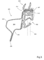
Figure 3 shows a cross-section A-A through a glassrun seal assembly 301 according to the invention mounted onto a header 300 a vehicle door. The cross-section A-A is taken at a curved portion of the glassrun seal assembly 301, indicated byreference 201 inFigure 2 . The glassrun seal assembly 301 comprises afirst portion 302 having a generally U-shaped cross section defining a glass run channel. When the vehicle window is closed, aglass pane 303 is arranged to extend upwards into theglass run channel 302, as indicated with dashed lines. Theglass run seal 301 assembly further comprises asecond portion 304 having a generally U-shaped cross section, defining an attachment channel. Theheader 300 shown inFigure 3 is made up of two profiledsheet metal components second edge portion closed section 309. Thefirst edge portion 307 formed by the assembledsheet metal components run seal assembly 301. The glassrun seal assembly 301 is retained in position by means of cooperating projections and recesses (not shown) on thefirst edge portion 307 and theattachment channel 304, respectively. - An
optional metal trim 310 having the same curvature as the glass run seal assembly can be arranged to cover at least a part of the outer surfaces of the first andsecond portions Figure 3 , themetal trim 310 is T-shaped, wherein its stem is retained in a recess between the first andsecond portions -
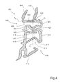
Figure 4 shows a cross-section A-A (seeFigure 2 ) through a glassrun seal assembly 401 as schematically shown inFigures 2 and3 . The glassrun seal assembly 401 comprises afirst portion 410 having a generally U-shaped cross section defining aglass run channel 410. The U-shapedglass run channel 410 has first andsecond legs first base web 413, wherein the first andsecond legs first portion 410 comprises an extruded elastomeric material bonded to thebase web 413, which base web comprises an extruded thermoplastic polymeric structural material. The first andsecond legs glass run channel 410 are each provided with sealinglips glass run channel 410 along the longitudinal extension of the glassrun seal assembly 401. The sealinglips second legs lips second legs - In the example shown in
Figure 4 , thefirst leg 411 forms an inner part of theglass run channel 410 and thesecond leg 412 forms an outer part of theglass run channel 410. The inner,first leg 411 comprises a first and asecond sealing lip glass run channel 410. Thefirst leg 411 further comprises anupper sealing lips 416 extending into the U-shaped channel substantially at right angles to thefirst leg 411. Theupper sealing lip 416 is arranged to contact and seal against the upper edge of a pane located in theglass run channel 410. The outer,second leg 412 comprises a sealinglip 417 extending upwards at an angle into the U-shaped channel opposite thesecond sealing lip 415 of thefirst leg 411. The sealinglip 417 is arranged to contact and seal against the outer surface of a pane located in theglass run channel 410. As indicated above, the sealinglips Figure 3 ) moving into theglass run channel 410 to close the window aperture 105 (Figure 1 ). - The glass
run seal assembly 401 further comprises asecond portion 420 having a generally U-shaped cross section, defining anattachment channel 420. Theattachment channel 420 has a first and asecond leg second base web 423. Thelegs base web 423 of theattachment channel 420 comprise an extruded thermoplastic polymeric structural material. Thefirst leg 421 of theattachment channel 420 has anedge 424 remote from itsbase web 423, whichedge 424 is bonded to and integral with thebase web 413 of theglass run channel 410. In this way, theglass run channel 410 and theattachment channel 420 are connected to form a glass run seal assembly. Further, thebase web 423 of theattachment channel 420 forms an outer surface extending substantially flush with thesecond leg 412 of theglass run channel 410. Thefirst leg 421 extends inwards, away from the outer surfaces of theattachment channel 420 and theglass run channel 410 towards thebase web 413 of theglass run channel 410. Thesecond leg 422 forms an upper part of theattachment channel 420 and extends inwards substantially parallel to a corresponding portion of a door opening in the chassis (not shown). The upper,second leg 422 comprises a first and asecond sealing lip U-shaped attachment channel 420. The first and second sealinglips attachment channel 420. - The
second leg 422 of theattachment channel 420 comprises areinforcement 430 extending within thesecond leg 422 in the longitudinal extension thereof. Thereinforcement 430 provides structural support a locally curved section 431 (seeFigure 2 ) of the glass run seal assembly. In addition, thesecond leg 422 of theattachment channel 420 with thereinforcement 430 has a lower coefficient of thermal expansion than thefirst leg 421 of theattachment channel 420. InFigure 4 , a first plane X1 is located at the central axis of, and in the main direction of, theU-shaped opening 418 into theglass run channel 410. A second plane X2 is located at the central axis of, and in the main direction of, theU-shaped opening 428 into theattachment channel 420. - As shown in
Figure 4 , thereinforcement 430 is arranged so that a cross-section (section A-A;Figure 2 ) through thereinforcement 430 has a major extension in a third plane X3 located at right angles to the first plane X1 in the main direction of theU-shaped opening 418 into theglass run channel 410. Consequently, thereinforcement 430 has a major extension in a plane X3 located at right angles to the plane of an upper portion of a pane (not shown) to be located in theopening 418 of theglass run channel 410 at that cross-section. The main direction of theU-shaped opening 418 into the glass run channel will coincide with a line R at right angles to a tangent T to the glass run seal assembly at each point along a curved section of the assembly (shown for section A-A inFigure 2 ). In the example shown inFigure 4 , the plane X3 through the major extension of thereinforcement 430 is parallel to the central plane X2 into theopening 428 of theattachment channel 420. In the example shown inFigure 4 , the first plane X1 of theU-shaped opening 418 extending into theglass run channel 410 is also arranged to intersect thereinforcement 430 in thesecond leg 422 of theattachment channel 420. This arrangement of thereinforcement 430 allows the glassrun seal assembly 401 to form a curve in a plane at right angles to the major extension of thereinforcement 430. - The
reinforcement 430 preferably, but not necessarily, comprises a metal core. According to one example the metal core comprises at least one metal strip. In the case of a single metal strip, as shown inFigure 4 , a cross-section of the strip can have a major extension, or width, within the range 2-8 mm and a minor extension, or thickness, within the range 0.1-1 mm and comprises a metal such as copper, aluminium or an aluminium alloy. Alternatively, the reinforcement can comprise two or more metal strips arranged side by side. The dimensions of multiple strips are chosen to provide the same mechanical properties as for a single strip. - According to a further alternative the reinforcement can comprise multiple parallel, intertwined or woven metal wires or threads/fibres of a suitable plastic material, such as glass fibre. As in the above examples, the reinforcement has major extension, or width, and a minor extension, or thickness, in order to provide the second leg of the attachment channel with the desired properties relating to the coefficient of thermal expansion.
- A
reinforcement 430 as described above is arranged to extend within at least one longitudinal section of theattachment channel 420 where the glassrun seal assembly 401 has a curvature. As indicated above, at least onereinforcement 430 is arranged to extend within thesecond leg 422 of theattachment channel 420 in the longitudinal extension thereof to provide structural support for a corresponding curved section of the glassrun seal assembly 401. Hence, the reinforcement is not arranged throughout the entire length of the glass run assembly. Areinforcement 430 is only required adjacent a length L of a curved section of theassembly 401, as shown inFigure 2 , where it is desired to prevent bulges or wrinkles along a curved section of the glassrun seal assembly 401. - The first and
second legs base web 423 of theattachment channel 420 and thebase web 413 of theglass run channel 410 comprise a thermoplastic polymeric structural material. A suitable material for this purpose is a structural grade polypropylene (PP). As all portions of the glassrun seal assembly 401 are formed by simultaneous co-extrusion, thereinforcement 430 should have an outer surface having suitable properties for achieving good adhesion with the thermoplastic polymeric structural material. Such adhesive properties can be provided by the material making up the reinforcement itself, a suitable surface treatment thereof, or by a coating applied to the material. - The first and
second legs glass run channel 410 comprises elastomeric extrusions co-extruded with and bonded to theirbase web 413 to form a U-shapedglass run channel 410. The first andsecond legs glass run channel 410 comprises thermoplastic vulcanizates (TPV), also termed elastomeric alloys (EA) or dynamically vulcanized thermoplastic elastomers (TPE). The first andsecond legs glass run channel 410 and their sealinglips second legs attachment channel 420 and their sealinglips lips - The
attachment channel 420 is formed of a polymeric material, and preferably a polymeric material having sufficient rigidity to perform the intended functions. A material that has been found suitable is a structural grade polypropylene. It is understood that comparably rigid thermoset materials can be employed. However, use of thermoset materials requires additional processing steps for recycling of the thermoset materials. In contrast, thermoplastic materials can be readily re-melted and reconfigured into subsequent products. - The
attachment channel 420 can be formed from a number of alternative plastic materials, for example, thermoplastics and thermoplastic elastomers (TPE). Depending on the hardness, TPE:s are sometimes categorized as thermoplastics and sometimes as elastomers. For purposes of this invention, no such distinction will be made, and hard and soft grades of plastic will all be referred to as TPE:s. TPE:s are commercially available in several different brands and types. Each type can be obtained in different grades having different properties such as hardness, tensile strength, compression, elongation, thermal stability and colorability. Selection of the appropriate TPE for a particular application depends on a suitable combination for such properties. Types of TPE that are particularly useful are styrenic block co-polymers, rubber polyolefin blends, elastomeric alloys, thermoplastic alloys, thermoplastic elastomeric alloys, thermoplastic isomers, thermoplastic polyurethanes, polyvinyl chlorides and blends thereof. - Polyvinyl chloride (PVC) based TPE:s are also suitable for window seals and are available in different grades and blends with other TPE:s and rubbers. Thermoplastic vulcanizates (TPV) with a relatively softer grade can be extruded to make profiles and seals. Thermoplastic vulcanizates comprises thermoplastic matrices, preferably crystalline, through which thermoset elastomers are generally uniformly distributed. Examples of thermoplastic vulcanizates include ethylene-propylene monomer rubber and ethylene-propylene-diene monomer rubber thermoset materials distributed in a crystalline polypropylene matrix. One example of a commercial TPV is Satoprene® thermoplastic rubber which is manufactured by Advanced Elastomer Systems and is a mixture of crosslinked EPDM particles in a crystalline polypropylene matrix. These materials have found utility in many applications which previously used vulcanized rubber, e.g., hoses, gaskets, and the like. Commercial TPV:s are typically based on vulcanized rubbers in which a phenolic resin or sulfur cure system is used to vulcanize, that is to crosslink, a diene (or more generally, a polyene) copolymer rubber by way of dynamic vulcanization, that is crosslinking while mixing (typically vigorously), in a thermoplastic matrix. TPV:s typically include a rubber component, a thermoplastic component, additive oil and other ingredients such as curing additives and the like. A variety of properties of TPVs are considered to be important, including but not limited to rebound, tensile strength and elongation, as well as varying degrees of softness or hardness.
- The glass contacting sealing lips of the header glass run channel can include a low friction surface which may be comprised of any suitable low friction material such as silicone, polyurethane, low friction flocking, or polypropylene.
-
Figure 5 shows a schematic diagram for a method of manufacturing a glass run seal assembly according to the invention. The method involves performing a number of process steps in sequence once the process is started 500. Afirst step 501 involves extruding an elastomeric material forming individual first andsecond legs first portion 410 intended to form aglass run channel 410. Thefirst step 501 involves simultaneous extrusion of a thermoplastic material forming asecond portion 420 having a generally U-shaped cross section defining anattachment channel 420, thesecond portion 420 having first andsecond legs base web 423, and afurther base web 413 bonding with the extruded elastomeric material of the first andsecond legs first portion 410 to form a generally U-shaped cross section defining theglass run channel 410, thefurther base web 413 being integral with anedge 424 of thefirst leg 421 of thesecond portion 410. - A
second step 502 is performed during the simultaneous co-extrusion of theglass run channel 410 and theattachment channel 420. Thesecond step 502 involves inserting areinforcement 430 into thesecond leg 422 of thesecond portion 420 in at least one predetermined section L (Figure 2 ) during extrusion of the thermoplastic material, wherein the co-extruded materials form a glassrun seal assembly 401. - A
third step 503 is performed after the first andsecond steps third step 503 involves cooling the extruded glassrun seal assembly 401 and allowing thefirst leg 421 of thesecond portion 420 and the extruded first andsecond legs first portion 410 to shrink in the longitudinal direction relative to the reinforcedsecond leg 422 of thesecond portion 420. As the section L (Figure 2 ) of thesecond leg 422 of thesecond portion 420 comprising thereinforcement 430 has a lower coefficient of thermal expansion than the remaining a glassrun seal assembly 401, the glassrun seal assembly 401 will bend during cooling to assume predetermined curvature. Once the glassrun seal assembly 401 has cooled to ambient temperature, the process ends 504. - The method involves inserting the
reinforcement 430 so that a cross-section through thereinforcement 430 has a major extension in a plane X3 located at right angles to a first plane X1 in the main direction of theU-shaped opening 418 into theglass run channel 410. In addition insertion of thereinforcement 430 can be performed so that the first plane X1 of theU-shaped opening 418 into theglass run channel 410 is arranged to intersect thereinforcement 430. - The method preferably involves using a reinforcement comprising at least one metal strip. Alternative types of reinforcements to be inserted during the
second step 502 have been listed above. - As described above, the
reinforcement 430 is inserted into thesecond leg 422 of thesecond portion 420 at predetermined locations during extrusion of the glassrun seal assembly 401. In this way thereinforcement 430 is arranged to extend within at least one longitudinal section L of thesecond leg 422 where the glassrun seal assembly 401 will require a curvature following the shape of a vehicle window aperture (Figure 1 &2 ). The reinforcinginsert 430 is located within a section L of the glassrun seal assembly 401 comprising a thermoplastic polymeric structural material, such as structural polypropylene (PP). The glassrun seal assembly 401 is hot and malleable after the extrusion process. During cooling the reinforcement/insert 430 prevents the thermoplastic polymeric structural material in thesecond leg 422 of the second portion from shrinking. At the same time, the thermoplastic polymeric structural material in thefirst leg 421 of thesecond portion 420 and the elastomeric material in the remaining sections and seals are allowed to shrink during cooling. As thesecond leg 422 of thesecond portion 420 with thereinforcement 430 has a lower coefficient of thermal expansion than thefirst leg 421 of thesecond portion 420 the glassrun seal assembly 401 will bend to form a curvature without wrinkles. The glassrun seal assembly 401 will bend in a plane XY located at right angles to a plane X3 in the major extension of a cross-section through thereinforcement 430. - According to a preferred example, the invention relates to a glass
run seal assembly 401 comprising a metal insert, such as an aluminium strip, that prevents the assembly from wrinkling during cooling and subsequent mounting onto a curved section the window opening of a vehicle door. - The above process steps only describe the basic structural sections of a glass run seal assembly according to the invention, which sections comprise an attachment channel with a reinforcement and a glass run channel. However, the extrusion process can involve additional component parts being co-extruded with their respective basic structural section. Examples of such additional component parts are sealing lips.
- During the extrusion process the a
glass run channel 410 can be provided with sealinglips attachment channel 420 can be provided with sealinglips lips - The invention is not limited to the above examples, but may be varied within the scope of the invention. For instance, the relative positions of the
glass run channel 410 and theattachment channel 420, as well as the location and number of sealing lips, is not limited to the examples given in the text above.
Claims (15)
- A glass run seal assembly (201; 301; 401) for a movable pane in a vehicle window aperture (105, 106), the glass run seal assembly comprising:- a first portion (410) having a generally U-shaped cross section defining a glass run channel having first and second legs (411, 412) with edges joined by a first base web (413), wherein at least the legs (411, 412) of the first portion (410) comprises elastomeric extrusions bonded to the base web (413); and- a second portion (420) having a generally U-shaped cross section defining an attachment channel having first and second legs (421, 422) with edges joined by a second base web (423), wherein the legs (421, 422) and base web (423) of the second portion (420) comprises a thermoplastic polymeric structural material, characterized in thatthe first leg (421) of the second portion (420) has an edge remote from its base web (423), which edge is integral the base web (413) of the first portion (410), and
the second leg (422) of the second portion (420) comprises a reinforcement (430) extending within the second leg (422) in the longitudinal extension thereof and providing structural support for at least one curved section of the glass run seal assembly (401). - A glass run seal assembly according to claim 1, characterized in that the second leg (422) of the second portion (420) with the reinforcement (430) has a lower coefficient of thermal expansion than the first leg (421) of the second portion (420).
- A glass run seal assembly according to claim 1 or 2, characterized in that a cross-section through the reinforcement (430) has a major extension in a plane (X3) located at right angles to the main direction (X1) of the U-shaped opening (418) into the glass run channel (410).
- A glass run seal assembly according to any one of the above claims, characterized in that the central axis of the U-shaped opening into the glass run channel is arranged to intersect the reinforcement (430).
- A glass run seal assembly according to any one of the above claims, characterized in that the reinforcement (430) comprises a metal core.
- A glass run seal assembly according to claim 2 or 3, characterized in that the reinforcement (430) comprises at least one metal strip.
- A glass run seal assembly according to claim 5 or 6, characterized in that the metal core comprises copper, aluminium or an aluminium alloy.
- A glass run seal assembly according to any one of the above claims, characterized i n that the second portion (420) and the base web (413) of the first portion (410) comprise a structural grade polypropylene.
- A glass run seal assembly according to any one of the above claims, characterized in that the first and second legs (411, 412) of the first portion (410) comprise thermoplastic vulcanizates.
- A glass run seal assembly according to any one of the above claims, characterized in that a reinforcement (430) is arranged to extend within at least one longitudinal section (L) of the second leg (422) where the glass run seal assembly has a curvature.
- A method for manufacturing a glass run seal assembly, characterized by, performing the steps of:- extruding (501) an elastomeric material forming individual first and second legs (411, 412) for a first portion (410) intended to form a glass run channel;- simultaneously extruding (501) a thermoplastic material forming a second portion (420) having a generally U-shaped cross section defining an attachment channel, the second portion having first and second legs (421, 422) with edges joined by a base web (423), and a further base web (413) bonding with the extruded elastomeric material of the first and second legs (411, 412) of the first portion (410) to form a generally U-shaped cross section defining the glass run channel, the further base web (413) being integral with an edge (424) of the first leg (421) of the second portion (420);- inserting (502) a reinforcement (430) into the second leg (422) of the second portion (420) during extrusion of the thermoplastic material, wherein the co-extruded materials form a glass run seal assembly; and- cooling (503) the glass run seal assembly and allowing the first leg (421) of the second portion (420) and the extruded first and second legs (411, 412) of the first portion (410) to shrink in the longitudinal direction relative to the reinforced second leg (422) of the second portion (420), forming a glass run seal assembly having a predetermined curvature.
- Method according to claim 11, characterized by inserting the reinforcement (430) so that a cross-section through the metal core has a major extension in a plane located at right angles to the main direction of the U-shaped opening into the glass run channel.
- Method according to claim 11 or 12, characterized by inserting the reinforcement so that the central axis of the U-shaped opening into the glass run channel is arranged to intersect the reinforcement (430).
- Method according to any one of claims 11-13, characterized by using a reinforcement (430) comprising at least one metal strip.
- Method according to any one of claims 11-14, characterized by locating the reinforcement (430) to extend within at least one longitudinal section (L) of the second leg (422) where the glass run seal assembly has a curvature.
Priority Applications (1)
| Application Number | Priority Date | Filing Date | Title |
|---|---|---|---|
| EP14168276.5A EP2944492B1 (en) | 2014-05-14 | 2014-05-14 | A glass run seal for a movable pane in a vehicle window aperture. |
Applications Claiming Priority (1)
| Application Number | Priority Date | Filing Date | Title |
|---|---|---|---|
| EP14168276.5A EP2944492B1 (en) | 2014-05-14 | 2014-05-14 | A glass run seal for a movable pane in a vehicle window aperture. |
Publications (2)
| Publication Number | Publication Date |
|---|---|
| EP2944492A1 true EP2944492A1 (en) | 2015-11-18 |
| EP2944492B1 EP2944492B1 (en) | 2019-09-11 |
Family
ID=50721620
Family Applications (1)
| Application Number | Title | Priority Date | Filing Date |
|---|---|---|---|
| EP14168276.5A Active EP2944492B1 (en) | 2014-05-14 | 2014-05-14 | A glass run seal for a movable pane in a vehicle window aperture. |
Country Status (1)
| Country | Link |
|---|---|
| EP (1) | EP2944492B1 (en) |
Cited By (2)
| Publication number | Priority date | Publication date | Assignee | Title |
|---|---|---|---|---|
| DE102020113445A1 (en) * | 2020-05-18 | 2021-04-29 | Audi Aktiengesellschaft | Window guide seal |
| US20250083507A1 (en) * | 2023-09-11 | 2025-03-13 | Nishikawa Rubber Co., Ltd. | Glass run for automotive door |
Citations (6)
| Publication number | Priority date | Publication date | Assignee | Title |
|---|---|---|---|---|
| GB2093407A (en) | 1981-01-23 | 1982-09-02 | Creators Ltd | Plastics trim strips |
| EP0638463A1 (en) * | 1993-08-09 | 1995-02-15 | Hutchinson | Sealing device of the type having a fixation element on a support or frame of a motor-vehicle and a sealing element |
| DE102006060390B3 (en) * | 2006-12-20 | 2008-02-07 | Metzeler Automotive Profile Systems Gmbh | Door sealing profile for e.g. car, has sealing section with sealing lip extending in longitudinal direction, and auxiliary section provided and arranged in area of curvature at base of sealing lip |
| DE202009005632U1 (en) * | 2009-04-15 | 2009-06-18 | GRÜTER, Achim | In the course of the seal optically flush window guide for motor vehicles with a plastic carrier or hard plastic-like material carrier with integrated metal core or metal band reinforcement |
| EP2594421A1 (en) * | 2011-11-16 | 2013-05-22 | Volvo Car Corporation | Seal assembly |
| US20130305612A1 (en) * | 2012-05-15 | 2013-11-21 | Henniges Automotive Sealing Systems North America, Inc. | Sealing member |
-
2014
- 2014-05-14 EP EP14168276.5A patent/EP2944492B1/en active Active
Patent Citations (6)
| Publication number | Priority date | Publication date | Assignee | Title |
|---|---|---|---|---|
| GB2093407A (en) | 1981-01-23 | 1982-09-02 | Creators Ltd | Plastics trim strips |
| EP0638463A1 (en) * | 1993-08-09 | 1995-02-15 | Hutchinson | Sealing device of the type having a fixation element on a support or frame of a motor-vehicle and a sealing element |
| DE102006060390B3 (en) * | 2006-12-20 | 2008-02-07 | Metzeler Automotive Profile Systems Gmbh | Door sealing profile for e.g. car, has sealing section with sealing lip extending in longitudinal direction, and auxiliary section provided and arranged in area of curvature at base of sealing lip |
| DE202009005632U1 (en) * | 2009-04-15 | 2009-06-18 | GRÜTER, Achim | In the course of the seal optically flush window guide for motor vehicles with a plastic carrier or hard plastic-like material carrier with integrated metal core or metal band reinforcement |
| EP2594421A1 (en) * | 2011-11-16 | 2013-05-22 | Volvo Car Corporation | Seal assembly |
| US20130305612A1 (en) * | 2012-05-15 | 2013-11-21 | Henniges Automotive Sealing Systems North America, Inc. | Sealing member |
Cited By (3)
| Publication number | Priority date | Publication date | Assignee | Title |
|---|---|---|---|---|
| DE102020113445A1 (en) * | 2020-05-18 | 2021-04-29 | Audi Aktiengesellschaft | Window guide seal |
| US20250083507A1 (en) * | 2023-09-11 | 2025-03-13 | Nishikawa Rubber Co., Ltd. | Glass run for automotive door |
| US12472805B2 (en) * | 2023-09-11 | 2025-11-18 | Nishikawa Rubber Co., Ltd. | Glass run for automotive door |
Also Published As
| Publication number | Publication date |
|---|---|
| EP2944492B1 (en) | 2019-09-11 |
Similar Documents
| Publication | Publication Date | Title |
|---|---|---|
| EP1040950B1 (en) | Seals for vehicles | |
| KR100349822B1 (en) | Flush Glass Sealing System | |
| CA2002907C (en) | Manufacture of composite extrusions | |
| US6070364A (en) | Flush glass seal insert with a belt-line extension | |
| EP1849639B1 (en) | Automobile weather strip | |
| EP3113966B1 (en) | Method of manufacturing a vehicle sealing assembly | |
| US5736215A (en) | Process for the manufacture of a profile part | |
| US8375640B2 (en) | Flange engaging strip with a carrier for engaging a flange having a varying thickness along a longitudinal dimension | |
| JP3030542U (en) | Composite member composed of thermoplastic material and elastomer material and apparatus for manufacturing the composite member | |
| EP2944492B1 (en) | A glass run seal for a movable pane in a vehicle window aperture. | |
| US7293820B2 (en) | Weather strip for motor vehicle | |
| EP0540183B1 (en) | Sealing strip | |
| US11623587B2 (en) | System and method for multi-shot injection molded roof ditch molding with multiple complex curvature | |
| JP2014196054A (en) | Opening trim weather strip | |
| JP2008030525A (en) | Weather strip | |
| JP6672131B2 (en) | Method of manufacturing trim material for vehicles | |
| EP2949493B1 (en) | A sealing assembly for a frameless sliding window | |
| EP3308931B1 (en) | Method for forming a glass run channel assembly | |
| JP4407469B2 (en) | Weather strip for automobile | |
| JP4672477B2 (en) | Manufacturing method of weather strip for automobile | |
| JP2016222146A (en) | Weather strip for vehicle and its manufacturing method | |
| JP2002219945A (en) | Seal strip manufacturing method and seal strip obtained by the method | |
| JP2007297434A (en) | Extrusion molded body and seal member for automobile using the same extrusion molded body | |
| JP2007296896A (en) | Seal member for automobile | |
| JP2008132849A (en) | Weather strip and manufacturing method thereof |
Legal Events
| Date | Code | Title | Description |
|---|---|---|---|
| PUAI | Public reference made under article 153(3) epc to a published international application that has entered the european phase |
Free format text: ORIGINAL CODE: 0009012 |
|
| AK | Designated contracting states |
Kind code of ref document: A1 Designated state(s): AL AT BE BG CH CY CZ DE DK EE ES FI FR GB GR HR HU IE IS IT LI LT LU LV MC MK MT NL NO PL PT RO RS SE SI SK SM TR |
|
| AX | Request for extension of the european patent |
Extension state: BA ME |
|
| 17P | Request for examination filed |
Effective date: 20160518 |
|
| RBV | Designated contracting states (corrected) |
Designated state(s): AL AT BE BG CH CY CZ DE DK EE ES FI FR GB GR HR HU IE IS IT LI LT LU LV MC MK MT NL NO PL PT RO RS SE SI SK SM TR |
|
| REG | Reference to a national code |
Ref country code: DE Ref legal event code: R079 Ref document number: 602014053305 Country of ref document: DE Free format text: PREVIOUS MAIN CLASS: B60J0010080000 Ipc: B60J0010160000 |
|
| GRAP | Despatch of communication of intention to grant a patent |
Free format text: ORIGINAL CODE: EPIDOSNIGR1 |
|
| STAA | Information on the status of an ep patent application or granted ep patent |
Free format text: STATUS: GRANT OF PATENT IS INTENDED |
|
| RIC1 | Information provided on ipc code assigned before grant |
Ipc: B60J 10/88 20160101ALI20190304BHEP Ipc: B60J 10/30 20160101ALI20190304BHEP Ipc: B60J 10/16 20160101AFI20190304BHEP Ipc: B60J 10/18 20160101ALI20190304BHEP Ipc: B60J 10/265 20160101ALI20190304BHEP |
|
| INTG | Intention to grant announced |
Effective date: 20190403 |
|
| GRAS | Grant fee paid |
Free format text: ORIGINAL CODE: EPIDOSNIGR3 |
|
| GRAA | (expected) grant |
Free format text: ORIGINAL CODE: 0009210 |
|
| STAA | Information on the status of an ep patent application or granted ep patent |
Free format text: STATUS: THE PATENT HAS BEEN GRANTED |
|
| AK | Designated contracting states |
Kind code of ref document: B1 Designated state(s): AL AT BE BG CH CY CZ DE DK EE ES FI FR GB GR HR HU IE IS IT LI LT LU LV MC MK MT NL NO PL PT RO RS SE SI SK SM TR |
|
| REG | Reference to a national code |
Ref country code: GB Ref legal event code: FG4D |
|
| REG | Reference to a national code |
Ref country code: CH Ref legal event code: EP |
|
| REG | Reference to a national code |
Ref country code: AT Ref legal event code: REF Ref document number: 1177987 Country of ref document: AT Kind code of ref document: T Effective date: 20190915 |
|
| REG | Reference to a national code |
Ref country code: DE Ref legal event code: R096 Ref document number: 602014053305 Country of ref document: DE Ref country code: IE Ref legal event code: FG4D |
|
| REG | Reference to a national code |
Ref country code: NL Ref legal event code: MP Effective date: 20190911 |
|
| REG | Reference to a national code |
Ref country code: LT Ref legal event code: MG4D |
|
| PG25 | Lapsed in a contracting state [announced via postgrant information from national office to epo] |
Ref country code: NO Free format text: LAPSE BECAUSE OF FAILURE TO SUBMIT A TRANSLATION OF THE DESCRIPTION OR TO PAY THE FEE WITHIN THE PRESCRIBED TIME-LIMIT Effective date: 20191211 Ref country code: SE Free format text: LAPSE BECAUSE OF FAILURE TO SUBMIT A TRANSLATION OF THE DESCRIPTION OR TO PAY THE FEE WITHIN THE PRESCRIBED TIME-LIMIT Effective date: 20190911 Ref country code: FI Free format text: LAPSE BECAUSE OF FAILURE TO SUBMIT A TRANSLATION OF THE DESCRIPTION OR TO PAY THE FEE WITHIN THE PRESCRIBED TIME-LIMIT Effective date: 20190911 Ref country code: HR Free format text: LAPSE BECAUSE OF FAILURE TO SUBMIT A TRANSLATION OF THE DESCRIPTION OR TO PAY THE FEE WITHIN THE PRESCRIBED TIME-LIMIT Effective date: 20190911 Ref country code: LT Free format text: LAPSE BECAUSE OF FAILURE TO SUBMIT A TRANSLATION OF THE DESCRIPTION OR TO PAY THE FEE WITHIN THE PRESCRIBED TIME-LIMIT Effective date: 20190911 Ref country code: BG Free format text: LAPSE BECAUSE OF FAILURE TO SUBMIT A TRANSLATION OF THE DESCRIPTION OR TO PAY THE FEE WITHIN THE PRESCRIBED TIME-LIMIT Effective date: 20191211 |
|
| PG25 | Lapsed in a contracting state [announced via postgrant information from national office to epo] |
Ref country code: AL Free format text: LAPSE BECAUSE OF FAILURE TO SUBMIT A TRANSLATION OF THE DESCRIPTION OR TO PAY THE FEE WITHIN THE PRESCRIBED TIME-LIMIT Effective date: 20190911 Ref country code: GR Free format text: LAPSE BECAUSE OF FAILURE TO SUBMIT A TRANSLATION OF THE DESCRIPTION OR TO PAY THE FEE WITHIN THE PRESCRIBED TIME-LIMIT Effective date: 20191212 Ref country code: ES Free format text: LAPSE BECAUSE OF FAILURE TO SUBMIT A TRANSLATION OF THE DESCRIPTION OR TO PAY THE FEE WITHIN THE PRESCRIBED TIME-LIMIT Effective date: 20190911 Ref country code: LV Free format text: LAPSE BECAUSE OF FAILURE TO SUBMIT A TRANSLATION OF THE DESCRIPTION OR TO PAY THE FEE WITHIN THE PRESCRIBED TIME-LIMIT Effective date: 20190911 Ref country code: RS Free format text: LAPSE BECAUSE OF FAILURE TO SUBMIT A TRANSLATION OF THE DESCRIPTION OR TO PAY THE FEE WITHIN THE PRESCRIBED TIME-LIMIT Effective date: 20190911 |
|
| REG | Reference to a national code |
Ref country code: AT Ref legal event code: MK05 Ref document number: 1177987 Country of ref document: AT Kind code of ref document: T Effective date: 20190911 |
|
| PG25 | Lapsed in a contracting state [announced via postgrant information from national office to epo] |
Ref country code: RO Free format text: LAPSE BECAUSE OF FAILURE TO SUBMIT A TRANSLATION OF THE DESCRIPTION OR TO PAY THE FEE WITHIN THE PRESCRIBED TIME-LIMIT Effective date: 20190911 Ref country code: PT Free format text: LAPSE BECAUSE OF FAILURE TO SUBMIT A TRANSLATION OF THE DESCRIPTION OR TO PAY THE FEE WITHIN THE PRESCRIBED TIME-LIMIT Effective date: 20200113 Ref country code: PL Free format text: LAPSE BECAUSE OF FAILURE TO SUBMIT A TRANSLATION OF THE DESCRIPTION OR TO PAY THE FEE WITHIN THE PRESCRIBED TIME-LIMIT Effective date: 20190911 Ref country code: EE Free format text: LAPSE BECAUSE OF FAILURE TO SUBMIT A TRANSLATION OF THE DESCRIPTION OR TO PAY THE FEE WITHIN THE PRESCRIBED TIME-LIMIT Effective date: 20190911 Ref country code: AT Free format text: LAPSE BECAUSE OF FAILURE TO SUBMIT A TRANSLATION OF THE DESCRIPTION OR TO PAY THE FEE WITHIN THE PRESCRIBED TIME-LIMIT Effective date: 20190911 Ref country code: NL Free format text: LAPSE BECAUSE OF FAILURE TO SUBMIT A TRANSLATION OF THE DESCRIPTION OR TO PAY THE FEE WITHIN THE PRESCRIBED TIME-LIMIT Effective date: 20190911 |
|
| PG25 | Lapsed in a contracting state [announced via postgrant information from national office to epo] |
Ref country code: IS Free format text: LAPSE BECAUSE OF FAILURE TO SUBMIT A TRANSLATION OF THE DESCRIPTION OR TO PAY THE FEE WITHIN THE PRESCRIBED TIME-LIMIT Effective date: 20200224 Ref country code: CZ Free format text: LAPSE BECAUSE OF FAILURE TO SUBMIT A TRANSLATION OF THE DESCRIPTION OR TO PAY THE FEE WITHIN THE PRESCRIBED TIME-LIMIT Effective date: 20190911 Ref country code: SM Free format text: LAPSE BECAUSE OF FAILURE TO SUBMIT A TRANSLATION OF THE DESCRIPTION OR TO PAY THE FEE WITHIN THE PRESCRIBED TIME-LIMIT Effective date: 20190911 Ref country code: SK Free format text: LAPSE BECAUSE OF FAILURE TO SUBMIT A TRANSLATION OF THE DESCRIPTION OR TO PAY THE FEE WITHIN THE PRESCRIBED TIME-LIMIT Effective date: 20190911 |
|
| REG | Reference to a national code |
Ref country code: DE Ref legal event code: R097 Ref document number: 602014053305 Country of ref document: DE |
|
| PLBE | No opposition filed within time limit |
Free format text: ORIGINAL CODE: 0009261 |
|
| STAA | Information on the status of an ep patent application or granted ep patent |
Free format text: STATUS: NO OPPOSITION FILED WITHIN TIME LIMIT |
|
| PG2D | Information on lapse in contracting state deleted |
Ref country code: IS |
|
| PG25 | Lapsed in a contracting state [announced via postgrant information from national office to epo] |
Ref country code: DK Free format text: LAPSE BECAUSE OF FAILURE TO SUBMIT A TRANSLATION OF THE DESCRIPTION OR TO PAY THE FEE WITHIN THE PRESCRIBED TIME-LIMIT Effective date: 20190911 Ref country code: IS Free format text: LAPSE BECAUSE OF FAILURE TO SUBMIT A TRANSLATION OF THE DESCRIPTION OR TO PAY THE FEE WITHIN THE PRESCRIBED TIME-LIMIT Effective date: 20200112 |
|
| 26N | No opposition filed |
Effective date: 20200615 |
|
| PG25 | Lapsed in a contracting state [announced via postgrant information from national office to epo] |
Ref country code: SI Free format text: LAPSE BECAUSE OF FAILURE TO SUBMIT A TRANSLATION OF THE DESCRIPTION OR TO PAY THE FEE WITHIN THE PRESCRIBED TIME-LIMIT Effective date: 20190911 |
|
| PG25 | Lapsed in a contracting state [announced via postgrant information from national office to epo] |
Ref country code: CH Free format text: LAPSE BECAUSE OF NON-PAYMENT OF DUE FEES Effective date: 20200531 Ref country code: LI Free format text: LAPSE BECAUSE OF NON-PAYMENT OF DUE FEES Effective date: 20200531 Ref country code: MC Free format text: LAPSE BECAUSE OF FAILURE TO SUBMIT A TRANSLATION OF THE DESCRIPTION OR TO PAY THE FEE WITHIN THE PRESCRIBED TIME-LIMIT Effective date: 20190911 |
|
| REG | Reference to a national code |
Ref country code: BE Ref legal event code: MM Effective date: 20200531 |
|
| GBPC | Gb: european patent ceased through non-payment of renewal fee |
Effective date: 20200514 |
|
| PG25 | Lapsed in a contracting state [announced via postgrant information from national office to epo] |
Ref country code: LU Free format text: LAPSE BECAUSE OF NON-PAYMENT OF DUE FEES Effective date: 20200514 |
|
| PG25 | Lapsed in a contracting state [announced via postgrant information from national office to epo] |
Ref country code: IE Free format text: LAPSE BECAUSE OF NON-PAYMENT OF DUE FEES Effective date: 20200514 Ref country code: GB Free format text: LAPSE BECAUSE OF NON-PAYMENT OF DUE FEES Effective date: 20200514 |
|
| PG25 | Lapsed in a contracting state [announced via postgrant information from national office to epo] |
Ref country code: BE Free format text: LAPSE BECAUSE OF NON-PAYMENT OF DUE FEES Effective date: 20200531 |
|
| PG25 | Lapsed in a contracting state [announced via postgrant information from national office to epo] |
Ref country code: TR Free format text: LAPSE BECAUSE OF FAILURE TO SUBMIT A TRANSLATION OF THE DESCRIPTION OR TO PAY THE FEE WITHIN THE PRESCRIBED TIME-LIMIT Effective date: 20190911 Ref country code: MT Free format text: LAPSE BECAUSE OF FAILURE TO SUBMIT A TRANSLATION OF THE DESCRIPTION OR TO PAY THE FEE WITHIN THE PRESCRIBED TIME-LIMIT Effective date: 20190911 Ref country code: CY Free format text: LAPSE BECAUSE OF FAILURE TO SUBMIT A TRANSLATION OF THE DESCRIPTION OR TO PAY THE FEE WITHIN THE PRESCRIBED TIME-LIMIT Effective date: 20190911 |
|
| PG25 | Lapsed in a contracting state [announced via postgrant information from national office to epo] |
Ref country code: MK Free format text: LAPSE BECAUSE OF FAILURE TO SUBMIT A TRANSLATION OF THE DESCRIPTION OR TO PAY THE FEE WITHIN THE PRESCRIBED TIME-LIMIT Effective date: 20190911 |
|
| P01 | Opt-out of the competence of the unified patent court (upc) registered |
Effective date: 20231212 |
|
| PGFP | Annual fee paid to national office [announced via postgrant information from national office to epo] |
Ref country code: DE Payment date: 20250423 Year of fee payment: 12 |
|
| PGFP | Annual fee paid to national office [announced via postgrant information from national office to epo] |
Ref country code: IT Payment date: 20250423 Year of fee payment: 12 |
|
| PGFP | Annual fee paid to national office [announced via postgrant information from national office to epo] |
Ref country code: FR Payment date: 20250423 Year of fee payment: 12 |