EP2944373B1 - Device for suspending cells - Google Patents
Device for suspending cells Download PDFInfo
- Publication number
- EP2944373B1 EP2944373B1 EP15166679.9A EP15166679A EP2944373B1 EP 2944373 B1 EP2944373 B1 EP 2944373B1 EP 15166679 A EP15166679 A EP 15166679A EP 2944373 B1 EP2944373 B1 EP 2944373B1
- Authority
- EP
- European Patent Office
- Prior art keywords
- mixing
- rod
- mount
- magnet
- mixing rod
- Prior art date
- Legal status (The legal status is an assumption and is not a legal conclusion. Google has not performed a legal analysis and makes no representation as to the accuracy of the status listed.)
- Active
Links
Images




Classifications
-
- B—PERFORMING OPERATIONS; TRANSPORTING
- B01—PHYSICAL OR CHEMICAL PROCESSES OR APPARATUS IN GENERAL
- B01F—MIXING, e.g. DISSOLVING, EMULSIFYING OR DISPERSING
- B01F33/00—Other mixers; Mixing plants; Combinations of mixers
- B01F33/45—Magnetic mixers; Mixers with magnetically driven stirrers
-
- C—CHEMISTRY; METALLURGY
- C12—BIOCHEMISTRY; BEER; SPIRITS; WINE; VINEGAR; MICROBIOLOGY; ENZYMOLOGY; MUTATION OR GENETIC ENGINEERING
- C12M—APPARATUS FOR ENZYMOLOGY OR MICROBIOLOGY; APPARATUS FOR CULTURING MICROORGANISMS FOR PRODUCING BIOMASS, FOR GROWING CELLS OR FOR OBTAINING FERMENTATION OR METABOLIC PRODUCTS, i.e. BIOREACTORS OR FERMENTERS
- C12M27/00—Means for mixing, agitating or circulating fluids in the vessel
- C12M27/02—Stirrer or mobile mixing elements
-
- B—PERFORMING OPERATIONS; TRANSPORTING
- B01—PHYSICAL OR CHEMICAL PROCESSES OR APPARATUS IN GENERAL
- B01F—MIXING, e.g. DISSOLVING, EMULSIFYING OR DISPERSING
- B01F31/00—Mixers with shaking, oscillating, or vibrating mechanisms
- B01F31/44—Mixers with shaking, oscillating, or vibrating mechanisms with stirrers performing an oscillatory, vibratory or shaking movement
- B01F31/441—Mixers with shaking, oscillating, or vibrating mechanisms with stirrers performing an oscillatory, vibratory or shaking movement performing a rectilinear reciprocating movement
-
- B—PERFORMING OPERATIONS; TRANSPORTING
- B01—PHYSICAL OR CHEMICAL PROCESSES OR APPARATUS IN GENERAL
- B01F—MIXING, e.g. DISSOLVING, EMULSIFYING OR DISPERSING
- B01F31/00—Mixers with shaking, oscillating, or vibrating mechanisms
- B01F31/44—Mixers with shaking, oscillating, or vibrating mechanisms with stirrers performing an oscillatory, vibratory or shaking movement
- B01F31/449—Stirrers constructions
-
- B—PERFORMING OPERATIONS; TRANSPORTING
- B01—PHYSICAL OR CHEMICAL PROCESSES OR APPARATUS IN GENERAL
- B01F—MIXING, e.g. DISSOLVING, EMULSIFYING OR DISPERSING
- B01F33/00—Other mixers; Mixing plants; Combinations of mixers
- B01F33/45—Magnetic mixers; Mixers with magnetically driven stirrers
- B01F33/453—Magnetic mixers; Mixers with magnetically driven stirrers using supported or suspended stirring elements
-
- B—PERFORMING OPERATIONS; TRANSPORTING
- B01—PHYSICAL OR CHEMICAL PROCESSES OR APPARATUS IN GENERAL
- B01F—MIXING, e.g. DISSOLVING, EMULSIFYING OR DISPERSING
- B01F35/00—Accessories for mixers; Auxiliary operations or auxiliary devices; Parts or details of general application
- B01F35/10—Maintenance of mixers
- B01F35/145—Washing or cleaning mixers not provided for in other groups in this subclass; Inhibiting build-up of material on machine parts using other means
- B01F35/1452—Washing or cleaning mixers not provided for in other groups in this subclass; Inhibiting build-up of material on machine parts using other means using fluids
- B01F35/1453—Washing or cleaning mixers not provided for in other groups in this subclass; Inhibiting build-up of material on machine parts using other means using fluids by means of jets of fluid, e.g. air
-
- B—PERFORMING OPERATIONS; TRANSPORTING
- B01—PHYSICAL OR CHEMICAL PROCESSES OR APPARATUS IN GENERAL
- B01F—MIXING, e.g. DISSOLVING, EMULSIFYING OR DISPERSING
- B01F35/00—Accessories for mixers; Auxiliary operations or auxiliary devices; Parts or details of general application
- B01F35/71—Feed mechanisms
- B01F35/712—Feed mechanisms for feeding fluids
-
- G—PHYSICS
- G01—MEASURING; TESTING
- G01N—INVESTIGATING OR ANALYSING MATERIALS BY DETERMINING THEIR CHEMICAL OR PHYSICAL PROPERTIES
- G01N1/00—Sampling; Preparing specimens for investigation
- G01N1/28—Preparing specimens for investigation including physical details of (bio-)chemical methods covered elsewhere, e.g. G01N33/50, C12Q
- G01N1/38—Diluting, dispersing or mixing samples
-
- B—PERFORMING OPERATIONS; TRANSPORTING
- B01—PHYSICAL OR CHEMICAL PROCESSES OR APPARATUS IN GENERAL
- B01F—MIXING, e.g. DISSOLVING, EMULSIFYING OR DISPERSING
- B01F2101/00—Mixing characterised by the nature of the mixed materials or by the application field
- B01F2101/23—Mixing of laboratory samples e.g. in preparation of analysing or testing properties of materials
-
- G—PHYSICS
- G01—MEASURING; TESTING
- G01N—INVESTIGATING OR ANALYSING MATERIALS BY DETERMINING THEIR CHEMICAL OR PHYSICAL PROPERTIES
- G01N35/00—Automatic analysis not limited to methods or materials provided for in any single one of groups G01N1/00 - G01N33/00; Handling materials therefor
- G01N35/10—Devices for transferring samples or any liquids to, in, or from, the analysis apparatus, e.g. suction devices, injection devices
- G01N2035/1027—General features of the devices
- G01N2035/1048—General features of the devices using the transfer device for another function
- G01N2035/1058—General features of the devices using the transfer device for another function for mixing
Definitions
- This invention relates to a method and a device for suspending particles in a fluid, especially for suspending living cells in small volume of fluids.
- Biological samples like cells need to be suspended in a liquid for culturing or analyzing purposes. Such suspensions are stable for short time until the sample starts sedimentation which makes remixing necessary.
- Mixing suspensions of biological samples is a long known technique for which a various devices are commercially available. Design and function of the mixing devices depend on the nature and volume of the sample to be mixed, the size and form of the mixing vessel and subsequent processing steps of the sample.
- EP53869 , US 3854704 and US 3572651 disclose a magnetic cell stirrer wherein the suspension is mixed by a rotating magnet placed in the mixing vessel via a flexible shaft.
- the magnet inside of the vessel is forced into rotational movement by a magnet outside of the vessel which in turn is rotated by a conventional magnetic stirring apparatus.
- the flexible shaft is attached to the mixing vessel and can not be removed or inserted in the vessel.
- US3780992 discloses a vibrating pipette, wherein a mechanical oscillator is attached to the pipette as mixing rod.
- US 4204774 describes a magnetic cell stirrer wherein the suspension is mixed by a rotating stirring rod.
- the rod is rotated in a circular path in the mixing vessel by an eccentric means and a synchronous motor.
- the magnetic cell stirrer is firmly attached to the mixing vessel and can not be removed or inserted in the vessel.
- Biological samples for testing or analyzing purposes are usually provided in small volumes ranging from less than 10 ⁇ l to 5 ml.
- commonly used microplates provide up to 1024 wells having a volume less than one milliliter.
- Mixing of such small volumes by mere stirring is difficult due to capillary forces and a low surface to volume ratio of the vessel resulting in adhesion of the liquid to the vessel walls.
- Mixing by stirring generates a single stream of liquid moving in a circle adjacent to the vessel wall having low turbulence and accordingly a low mixing efficiency.
- US2008/0078257 discloses a mixing process, and a mixing device according to the preamble of claim 1, wherein a magnetic mixing rod is moved by a second magnet rotating around the mixing rod.
- Suspensions in microplate wells are therefore usually mixed by shaking or vibrating the whole microplate i.e. all wells simultaneously. Shaking cell suspensions in a microplate might result in cell loss since cells can adhere to walls of a well above the surface of the liquid It would be beneficial to provide small volume suspensions of biological samples without stirring the fluid in circles and/or the need to shake/vibrate other vessels. It would furthermore be desirous to provide a device to generate such suspensions which can be implemented in analytical devices like a FACS machines for sample preparation upstream of the cell analysis device.
- particle suspensions especially in small volume containers can be efficiently homogenized by a device wherein a magnetic mixing rod is moved in an oscillating manner by interaction with rotating second magnet.
- object of the invention is a mixing device according to claim 1.
- a process for mixing a biological sample like a cell suspension is also disclosed by providing a biological sample in a liquid to a mixing vessel, submerging a mixing rod in the liquid and stir the liquid by a first magnet (1) rotating around a longitudinal axis (2); a mixing rod (4) attached to a mount (6), the mount including a second magnet (3), wherein the mount (6) moves in a substantially orthogonal motion to the longitudinal axis of the mixing rod (4) by the interaction of the rotating first magnet with the second magnet (3).
- the device of the invention it is possible to suspend particles even in small volumes of fluid without loss of particles or fluid due to spilling or re-agglomeration .
- mixing or “suspending” are synonym and are directed to provide a suspension of particles like cells in a fluid.
- the device according to the invention is especially useful for suspending particles like a biological sample in a liquid or fluid by the movement of the mixing rod (4) in the biological sample.
- Biological sample can be any type of tissue or cells to be suspended in an appropriate fluid like cell nutrition buffer.
- the preferred movement of the mixing rod (4) through the fluid is substantially orthogonal or lateral in view of the longitudinal axis of the mixing rod. Such movement and the resulting currents in the liquid is depicted in Fig. 6 with arrows indicating the direction of movement.
- convection currents of fluid By moving the mixing rod (4) (thin lines) through the fluid, convection currents of fluid (bold lines) result with a common zone of turbulence.
- the currents flow with opposite direction and share at least one common zone of turbulence.
- Essential for the mixing device according to the invention is the movement of the mixing rod (4) about the second axis (5).
- the term "substantially" means that the movement may deviate slightly from the lateral or movement.
- the drawing shows in thin line a substantial lateral paths of movement of the mixing rod.
- the movement of the mixing rod (4) is lateral i.e. orthogonal to the longitudinal axis of the mixing rod (4) as shown in Fig. 6b .
- the longitudinal axis (2) of the first magnet in quiescent state of the first magnet may by substantially coaxial with a rotational axis of the second magnet (3).
- the movement of the mixing rod originates from the rotation of the first magnet (1) around first axis (2). This rotational movement is transferred by magnetic interaction between the first magnet (1) and the second magnet (3) to the mount (6) and finally to the mixing rod (4). Magnetic interaction between the first magnet (1) and the second magnet (3) requires that the distance between the both magnets is sufficiently small. Depending on the orientation of the poles of the first and second magnet, the interaction may generate attracting or opposing forces. In the present invention, first and second magnets are preferable orientated with the same pole facing each other (N-N or S-S). The rotational movement of first magnet (1) and the opposing forces between the magnets "pushes" second magnet (3) into motion.
- First magnet (1) and the second magnet (3) are permanent magnets without any special requirements.
- the mixing rod (4) is guided by sleeve or guidance (10) which is attached to mount or hinge (6, 6').
- the moving path of the mixing rod (4) is defined or restricted by the mount (6, 6') that allows movement of the second magnet (3) about a second axis (5).
- the mount is provided as holder with one or two sheet-like hinges (6,6') which can only swing or vibrate about the second axis (5).
- mixing rod (4) is coupled to a mount (6) by a sleeve (10), wherein the sleeve allows movement of the mixing rod along its longitudinal axis.
- the orthogonal motion of the mixing rod may be accommodated by a plurality of joints disposed on at least two sides of the mount (6). This embodiment is shown in Fig. 3 and results in a substantial lateral movement of the mixing rod (4) along dashed line 6".
- rotation of the first magnet (1) is accomplished by an electric motor (8) which rotates around a first axis (2).
- the first magnet (1) may be fixed in line with the first axis (2) or in a preferred embodiment, asymmetric to the first axis (2) i.e. positioned with a distance of 1 - 5 mm to the first axis (2).
- a counterweight (9) to the first magnet (1) is positioned at the same distance to the first axis (2) to prevent imbalance.
- the mixing rod (4) is manufactured from a material like stainless steel or the like in contrast to flexible materials like polymers, rubber etc.
- the mixing rod (4) may be solid or provided as tube or cannula.
- the mixing rod (4) may be used for filling the mixing vessel with the particles and fluids to be mixed/suspended.
- the particles (biological sample/cells) and/or the fluid are at least in part inserted or removed from the mixing vessel through a mixing rod (4) provided as tube. Particles and fluids may already be premixed before being provided into the mixing vessel.
- mixing rod (4) is optionally provided with appropriate connectors like the Luer-system for connection with tubing set.
- the mixing device is provided with at least one mixing vessel and the mixing rod can be inserted into and withdrawn from the mixing vessel. Inserting/withdrawing of the mixing rod from the vessel requires either moving the mixing vessel relative to a stationary mixing rod or the mixing rod relative to a stationary mixing vessel.
- This variant is shown in Fig. 4 and 5 , with the position of mixing rod (4) being adjustable relative a not shown mixing vessel in direction of dashed line (13).
- the mixing device is provided with at least one mixing vessel containing a liquid below the mount (6), such that the mixing rod is submerged in the liquid so as to stir the liquid by the orthogonal motion.
- the mixing device further comprises a driver 14 coupled to the motor 8, that stops and reverses the motion of the mixing rod (4), as shown in Fig. 2 .
- the mixing device is provided with at least one mixing vessel and the mixing rod (4) is inserted and removed from the mixing vessel by moving the mixing vessel in the direction along the longitudinal axis of the mixing rod.
- the wells of commercially available microplates are preferred.
- the movement of the second magnet (3) and mixing rod (4) about the second axis (5) needs to be adjusted to the space available within the vessel.
- the mixing rod shall mix the liquid without touching the walls of the vessel throughout its movement.
- the method is preferable performed in a mixing vessel wherein the ratio of the outer diameter of the mixing rod (4) and the maximum inner width of the mixing vessel is between 0.1 and 0.3.
- the mixing rod may have an outer diameter of 1.5 to 0.3 mm and may be utilized in mixing vessels with an maximum inner width of 1 to 10 mm.
- the device of the invention can be used for mixing or suspending subsequently a plurality of different samples. It is another object of the invention to avoid contamination of a sample to be suspended by traces or drops of a different sample adhering to the mixing rod.
- the surface of the mixing rod is cleaned or stripped from adhering mixture by a cleaning pod or a cleaning liquid.
- the mount (6) may be provided with at least a cleaning pod that removes material from the mixing rod.
- the cleaning pod may be made from any material suitable for soaking up liquids like cotton or tissue paper.
- the mount (6) is provided with at least one orifice (11, 12) which allows the introduction of a liquid into the sleeve (10).
- the mixing rod is then guided through a reservoir of the cleaning liquid or through a stream of cleaning liquid, thereby assuring that the mixing rod is only in contact with fresh, uncontaminated cleaning liquid.
- Fig. 3 shows this embodiment of the invention, where joint or hinge (6, 6') is provided with sleeve or guidance (10) for the mixing rod (4) which can be flushed with cleaning liquid provided and removed through orifices (11) and (12).
- the device according to the invention is especially useful for sample preparation in automated processing or analyzing of biological samples.
- processing requires a homogenous suspension of the sample in a fluid.
- the homogenous sample is suspended in the fluid shortly before processing.
- a process for providing a suspension comprising: placing particles like a biological sample and a fluid in a mixing vessel; placing the mixing rod of the mixing device as described in the mixing vessel and suspending the particles in the liquid/fluid.
- the mixing rod may thereby mix the biological sample.
- the process can be utilized within high-throughput automates or robots for analyzing a plurality of biological samples. Therefore, multi-well microplates are preferable used as mixing vessel in the process and the mixing rod is inserted in each well /mixing vessel for mixing and withdrawn after suspending/mixing is completed.
- the device of the invention can be used for parallel processing of a plurality of samples. For example, suspending of a plurality of biological samples on multi-well microplates may be performed in parallel by 2 to 6 devices of the invention.
- the mixing device may comprise an additional 1 to 6 mixing rods (4) and mounts (10) which are driven in parallel.
- the mixing device may be used for larger volumes by using one mount (6) which includes a plurality of mixing rods (4).
- the mixing device of the invention can be used for any automated processing or automated analyzing of biological samples in suspension or solution, especially ELIZA or FACS systems.
Landscapes
- Chemical & Material Sciences (AREA)
- Chemical Kinetics & Catalysis (AREA)
- Life Sciences & Earth Sciences (AREA)
- Health & Medical Sciences (AREA)
- Biochemistry (AREA)
- Engineering & Computer Science (AREA)
- Bioinformatics & Cheminformatics (AREA)
- Organic Chemistry (AREA)
- General Health & Medical Sciences (AREA)
- Wood Science & Technology (AREA)
- Zoology (AREA)
- General Engineering & Computer Science (AREA)
- Sustainable Development (AREA)
- Microbiology (AREA)
- Genetics & Genomics (AREA)
- Biotechnology (AREA)
- Biomedical Technology (AREA)
- Physics & Mathematics (AREA)
- Analytical Chemistry (AREA)
- General Physics & Mathematics (AREA)
- Immunology (AREA)
- Pathology (AREA)
- Apparatus Associated With Microorganisms And Enzymes (AREA)
- Sampling And Sample Adjustment (AREA)
Description
- This invention relates to a method and a device for suspending particles in a fluid, especially for suspending living cells in small volume of fluids.
- Biological samples like cells need to be suspended in a liquid for culturing or analyzing purposes. Such suspensions are stable for short time until the sample starts sedimentation which makes remixing necessary. Mixing suspensions of biological samples is a long known technique for which a various devices are commercially available. Design and function of the mixing devices depend on the nature and volume of the sample to be mixed, the size and form of the mixing vessel and subsequent processing steps of the sample.
- Besides mixing a suspension by a stirrer coupled to an electric motor, magnetic cell stirrers are in common use. To provide larger volumes of suspensions,
EP53869 US 3854704 andUS 3572651 disclose a magnetic cell stirrer wherein the suspension is mixed by a rotating magnet placed in the mixing vessel via a flexible shaft. The magnet inside of the vessel is forced into rotational movement by a magnet outside of the vessel which in turn is rotated by a conventional magnetic stirring apparatus. The flexible shaft is attached to the mixing vessel and can not be removed or inserted in the vessel. -
US3780992 discloses a vibrating pipette, wherein a mechanical oscillator is attached to the pipette as mixing rod. -
US 4204774 describes a magnetic cell stirrer wherein the suspension is mixed by a rotating stirring rod. The rod is rotated in a circular path in the mixing vessel by an eccentric means and a synchronous motor. The magnetic cell stirrer is firmly attached to the mixing vessel and can not be removed or inserted in the vessel. - Biological samples for testing or analyzing purposes are usually provided in small volumes ranging from less than 10 µl to 5 ml. For example, commonly used microplates provide up to 1024 wells having a volume less than one milliliter. Mixing of such small volumes by mere stirring is difficult due to capillary forces and a low surface to volume ratio of the vessel resulting in adhesion of the liquid to the vessel walls. Mixing by stirring generates a single stream of liquid moving in a circle adjacent to the vessel wall having low turbulence and accordingly a low mixing efficiency.
- In this respect,
US2008/0078257 discloses a mixing process, and a mixing device according to the preamble ofclaim 1, wherein a magnetic mixing rod is moved by a second magnet rotating around the mixing rod. - Suspensions in microplate wells are therefore usually mixed by shaking or vibrating the whole microplate i.e. all wells simultaneously. Shaking cell suspensions in a microplate might result in cell loss since cells can adhere to walls of a well above the surface of the liquid It would be beneficial to provide small volume suspensions of biological samples without stirring the fluid in circles and/or the need to shake/vibrate other vessels. It would furthermore be desirous to provide a device to generate such suspensions which can be implemented in analytical devices like a FACS machines for sample preparation upstream of the cell analysis device.
- Surprisingly, it was found that particle suspensions, especially in small volume containers can be efficiently homogenized by a device wherein a magnetic mixing rod is moved in an oscillating manner by interaction with rotating second magnet.
- Accordingly, object of the invention is a mixing device according to
claim 1. A process for mixing a biological sample like a cell suspension is also disclosed by providing a biological sample in a liquid to a mixing vessel, submerging a mixing rod in the liquid and stir the liquid by a first magnet (1) rotating around a longitudinal axis (2); a mixing rod (4) attached to a mount (6), the mount including a second magnet (3), wherein the mount (6) moves in a substantially orthogonal motion to the longitudinal axis of the mixing rod (4) by the interaction of the rotating first magnet with the second magnet (3). - With the device of the invention, it is possible to suspend particles even in small volumes of fluid without loss of particles or fluid due to spilling or re-agglomeration .
- Within the scope of the invention, the terms "mixing" or "suspending" are synonym and are directed to provide a suspension of particles like cells in a fluid.
- The device according to the invention is especially useful for suspending particles like a biological sample in a liquid or fluid by the movement of the mixing rod (4) in the biological sample. "Biological sample" can be any type of tissue or cells to be suspended in an appropriate fluid like cell nutrition buffer.
-
- Fig. 1
- shows the device with first magnet (1), first longitudinal axis (2), second magnet (3), mixing rod (4), mount (6, 6') and second axis (5).
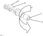
- Fig. 2
- shows the first magnet (1) mounted on electric motor (8) with counter weight (9) rotating around first longitudinal axis (2')
- Fig. 3
- shows second magnet (3) attached to the mount of mixing rod (4); hinged to joints (6, 6'). The joints are fixed by through holes (7), thereby movement of the mount is limited as depicted by dashed
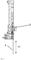
line 6". Mixing rod (4) is guided by sleeve (10). - Fig. 4
- side view of the mixing system with electric motor (8) and mixing rod (4)
- Fig. 5
- front view of the mixing system with the hinged joints (6, 6') for the mixing rod (4) removed. Mixing rod (4) is guided by holder or sleeve (10)
- Fig. 6
- Examples of movement of the mixing rod (4) (thin line) and resulting convection currents of fluids (bold line)
- The preferred movement of the mixing rod (4) through the fluid is substantially orthogonal or lateral in view of the longitudinal axis of the mixing rod. Such movement and the resulting currents in the liquid is depicted in
Fig. 6 with arrows indicating the direction of movement. By moving the mixing rod (4) (thin lines) through the fluid, convection currents of fluid (bold lines) result with a common zone of turbulence. The currents flow with opposite direction and share at least one common zone of turbulence. - Essential for the mixing device according to the invention is the movement of the mixing rod (4) about the second axis (5). The term "substantially" means that the movement may deviate slightly from the lateral or movement. For example, in
Fig. 6a , the drawing shows in thin line a substantial lateral paths of movement of the mixing rod. It is preferred that the movement of the mixing rod (4) is lateral i.e. orthogonal to the longitudinal axis of the mixing rod (4) as shown inFig. 6b . - In the mixing device according to the invention, in quiescent state of the first magnet the longitudinal axis (2) of the first magnet may by substantially coaxial with a rotational axis of the second magnet (3).
- The movement of the mixing rod originates from the rotation of the first magnet (1) around first axis (2). This rotational movement is transferred by magnetic interaction between the first magnet (1) and the second magnet (3) to the mount (6) and finally to the mixing rod (4). Magnetic interaction between the first magnet (1) and the second magnet (3) requires that the distance between the both magnets is sufficiently small. Depending on the orientation of the poles of the first and second magnet, the interaction may generate attracting or opposing forces. In the present invention, first and second magnets are preferable orientated with the same pole facing each other (N-N or S-S). The rotational movement of first magnet (1) and the opposing forces between the magnets "pushes" second magnet (3) into motion.
- First magnet (1) and the second magnet (3) are permanent magnets without any special requirements.
- In
Fig. 1 and3 , the mixing rod (4) is guided by sleeve or guidance (10) which is attached to mount or hinge (6, 6'). The moving path of the mixing rod (4) is defined or restricted by the mount (6, 6') that allows movement of the second magnet (3) about a second axis (5). According to the invention, the mount is provided as holder with one or two sheet-like hinges (6,6') which can only swing or vibrate about the second axis (5). - In a preferred embodiment of the mixing device, mixing rod (4) is coupled to a mount (6) by a sleeve (10), wherein the sleeve allows movement of the mixing rod along its longitudinal axis. The orthogonal motion of the mixing rod may be accommodated by a plurality of joints disposed on at least two sides of the mount (6). This embodiment is shown in
Fig. 3 and results in a substantial lateral movement of the mixing rod (4) along dashedline 6". - As shown in
Fig. 2 , rotation of the first magnet (1) is accomplished by an electric motor (8) which rotates around a first axis (2). The first magnet (1) may be fixed in line with the first axis (2) or in a preferred embodiment, asymmetric to the first axis (2) i.e. positioned with a distance of 1 - 5 mm to the first axis (2). In this embodiment, preferable a counterweight (9) to the first magnet (1) is positioned at the same distance to the first axis (2) to prevent imbalance. - The mixing rod (4) is manufactured from a material like stainless steel or the like in contrast to flexible materials like polymers, rubber etc. The mixing rod (4) may be solid or provided as tube or cannula.
- If provided as tube or cannula, the mixing rod (4) may be used for filling the mixing vessel with the particles and fluids to be mixed/suspended. In another variant of the invention, the particles (biological sample/cells) and/or the fluid are at least in part inserted or removed from the mixing vessel through a mixing rod (4) provided as tube. Particles and fluids may already be premixed before being provided into the mixing vessel. For this purpose, mixing rod (4) is optionally provided with appropriate connectors like the Luer-system for connection with tubing set.
- In yet another embodiment of the invention, the mixing device is provided with at least one mixing vessel and the mixing rod can be inserted into and withdrawn from the mixing vessel. Inserting/withdrawing of the mixing rod from the vessel requires either moving the mixing vessel relative to a stationary mixing rod or the mixing rod relative to a stationary mixing vessel. This variant is shown in
Fig. 4 and5 , with the position of mixing rod (4) being adjustable relative a not shown mixing vessel in direction of dashed line (13). - In a first variant of this embodiment of the invention, the mixing device is provided with at least one mixing vessel containing a liquid below the mount (6), such that the mixing rod is submerged in the liquid so as to stir the liquid by the orthogonal motion. In this variant, the mixing device further comprises a driver 14 coupled to the
motor 8, that stops and reverses the motion of the mixing rod (4), as shown inFig. 2 . - In a second variant of this embodiment of the invention, the mixing device is provided with at least one mixing vessel and the mixing rod (4) is inserted and removed from the mixing vessel by moving the mixing vessel in the direction along the longitudinal axis of the mixing rod.
- As mixing vessels, the wells of commercially available microplates are preferred. Of course, the movement of the second magnet (3) and mixing rod (4) about the second axis (5) needs to be adjusted to the space available within the vessel. The mixing rod shall mix the liquid without touching the walls of the vessel throughout its movement.
- The method is preferable performed in a mixing vessel wherein the ratio of the outer diameter of the mixing rod (4) and the maximum inner width of the mixing vessel is between 0.1 and 0.3. For example, the mixing rod may have an outer diameter of 1.5 to 0.3 mm and may be utilized in mixing vessels with an maximum inner width of 1 to 10 mm.
- The device of the invention can be used for mixing or suspending subsequently a plurality of different samples. It is another object of the invention to avoid contamination of a sample to be suspended by traces or drops of a different sample adhering to the mixing rod.
- In further embodiments of the invention, the surface of the mixing rod is cleaned or stripped from adhering mixture by a cleaning pod or a cleaning liquid. For this purpose, the mount (6) may be provided with at least a cleaning pod that removes material from the mixing rod. The cleaning pod may be made from any material suitable for soaking up liquids like cotton or tissue paper.
- Better cleaning of the mixing rod can be achieved by using a cleaning liquid and washing the mixing rod. In this embodiment of the invention, the mount (6) is provided with at least one orifice (11, 12) which allows the introduction of a liquid into the sleeve (10). The mixing rod is then guided through a reservoir of the cleaning liquid or through a stream of cleaning liquid, thereby assuring that the mixing rod is only in contact with fresh, uncontaminated cleaning liquid.
-
Fig. 3 shows this embodiment of the invention, where joint or hinge (6, 6') is provided with sleeve or guidance (10) for the mixing rod (4) which can be flushed with cleaning liquid provided and removed through orifices (11) and (12). - The device according to the invention is especially useful for sample preparation in automated processing or analyzing of biological samples. Usually, such processing requires a homogenous suspension of the sample in a fluid. At best, the homogenous sample is suspended in the fluid shortly before processing.
- Accordingly, a process for providing a suspension is also disclosed, comprising: placing particles like a biological sample and a fluid in a mixing vessel; placing the mixing rod of the mixing device as described in the mixing vessel and suspending the particles in the liquid/fluid. The mixing rod may thereby mix the biological sample.
- The process can be utilized within high-throughput automates or robots for analyzing a plurality of biological samples. Therefore, multi-well microplates are preferable used as mixing vessel in the process and the mixing rod is inserted in each well /mixing vessel for mixing and withdrawn after suspending/mixing is completed.
- The device of the invention can be used for parallel processing of a plurality of samples. For example, suspending of a plurality of biological samples on multi-well microplates may be performed in parallel by 2 to 6 devices of the invention. For this purpose, the mixing device may comprise an additional 1 to 6 mixing rods (4) and mounts (10) which are driven in parallel.
- On the other hand, the mixing device may be used for larger volumes by using one mount (6) which includes a plurality of mixing rods (4).
- The mixing device of the invention can be used for any automated processing or automated analyzing of biological samples in suspension or solution, especially ELIZA or FACS systems.
Claims (13)
- A mixing device comprising:a first magnet (1) rotating around a longitudinal axis (2);a mixing rod (4) attached to a mount, the mount including a second magnet (3) having a rotational axis, wherein the longitudinal axis (2) of the first magnet is substantially coaxial with the rotational axis of the second magnet (3), characterized in that the mount is provided as holder with one or two sheet-like hinges (6,6') which swing or vibrate about a second axis (5) such that the mount moves in a substantially orthogonal motion (6") to the longitudinal axis of the mixing rod (4) by magnetic interaction of the rotating first magnet with the second magnet (3).
- The mixing device according to claim 1, characterized in that the mixing rod is a tube.
- The mixing device according to claim 1 or 2, characterized in that the mixing rod (4) is coupled to a mount by a sleeve (10), wherein the sleeve allows movement of the mixing rod along its longitudinal axis.
- The mixing device according to any of the claims 1 to 3, characterized that mount is provided with at least one orifice (11, 12) which allows the introduction of a liquid into the sleeve (10).
- The mixing device according to any of the claims 1 to 3, characterized that mount is provided with at least a cleaning pod that removes material from the mixing rod.
- The mixing device according to any of the claims 1 to 5, characterized in that at least one mixing vessel containing a liquid is provided below the mount, such that the mixing rod (4) is submerged in the liquid so as to stir the liquid by the orthogonal motion.
- The mixing device according to any of the claims 1 to 5, characterized in that at least one mixing vessel is provided and the mixing rod (4) is inserted and removed from the mixing vessel by moving the mixing vessel in the direction along the longitudinal axis of the mixing rod (4).
- The mixing device according to any of the claims 1 to 7, wherein the mixing rod (4) does not touch the walls of the vessel throughout its movement.
- The mixing device according to any of the claims 6 to 8, wherein the outer diameter of the mixing rod (4) is between about 0.1 and 0.3 of a diameter of the vessel.
- The mixing device according to any of the claims 1 to 9, further comprising an additional 1 to 6 mixing rods (4) and mounts which are driven in parallel.
- The mixing device according to any of the claims 1 to 10, wherein the mount includes a plurality of mixing rods (4).
- The mixing device according to any of the claims 1 to 11, further comprising a driver that stops and reverses the motion of the mixing bar.
- The mixing device according to any of the claims 1 to 12 wherein the mixing rod (4) mixes a biological sample.
Priority Applications (1)
| Application Number | Priority Date | Filing Date | Title |
|---|---|---|---|
| EP15166679.9A EP2944373B1 (en) | 2014-05-17 | 2015-05-07 | Device for suspending cells |
Applications Claiming Priority (2)
| Application Number | Priority Date | Filing Date | Title |
|---|---|---|---|
| EP14168756.6A EP2944372A1 (en) | 2014-05-17 | 2014-05-17 | Method and device for suspending cells |
| EP15166679.9A EP2944373B1 (en) | 2014-05-17 | 2015-05-07 | Device for suspending cells |
Publications (2)
| Publication Number | Publication Date |
|---|---|
| EP2944373A1 EP2944373A1 (en) | 2015-11-18 |
| EP2944373B1 true EP2944373B1 (en) | 2018-06-20 |
Family
ID=50729402
Family Applications (2)
| Application Number | Title | Priority Date | Filing Date |
|---|---|---|---|
| EP14168756.6A Withdrawn EP2944372A1 (en) | 2014-05-17 | 2014-05-17 | Method and device for suspending cells |
| EP15166679.9A Active EP2944373B1 (en) | 2014-05-17 | 2015-05-07 | Device for suspending cells |
Family Applications Before (1)
| Application Number | Title | Priority Date | Filing Date |
|---|---|---|---|
| EP14168756.6A Withdrawn EP2944372A1 (en) | 2014-05-17 | 2014-05-17 | Method and device for suspending cells |
Country Status (3)
| Country | Link |
|---|---|
| US (1) | US20150328605A1 (en) |
| EP (2) | EP2944372A1 (en) |
| ES (1) | ES2687480T3 (en) |
Cited By (1)
| Publication number | Priority date | Publication date | Assignee | Title |
|---|---|---|---|---|
| USD1069156S1 (en) | 2023-04-10 | 2025-04-01 | Becton, Dickinson And Company | Dispensing device |
Families Citing this family (5)
| Publication number | Priority date | Publication date | Assignee | Title |
|---|---|---|---|---|
| US9956534B2 (en) * | 2014-05-17 | 2018-05-01 | Miltenyi Biotec, Gmbh | Method and device for suspending cells |
| US20170241911A1 (en) | 2016-02-22 | 2017-08-24 | Miltenyi Biotec Gmbh | Automated analysis tool for biological specimens |
| CN109261039B (en) * | 2018-11-30 | 2023-05-30 | 中国科学院高能物理研究所 | Oscillating device for liquid stirring, application and liquid stirring method |
| CN111238414B (en) * | 2020-03-25 | 2025-03-14 | 宝鸡志普有色金属加工有限公司 | Tungsten wire rope sway crystal testing system and method |
| CN112123610B (en) * | 2020-08-04 | 2022-02-01 | 南通瑞智新材料科技有限公司 | Internal-moving type automatic material-supplementing plastic stirring method |
Citations (1)
| Publication number | Priority date | Publication date | Assignee | Title |
|---|---|---|---|---|
| US4046515A (en) * | 1975-03-27 | 1977-09-06 | Leeuw Jan De | Diluting and agitating device |
Family Cites Families (37)
| Publication number | Priority date | Publication date | Assignee | Title |
|---|---|---|---|---|
| US2459869A (en) * | 1946-08-10 | 1949-01-25 | Bell Telephone Labor Inc | Crystal growing apparatus |
| US2932493A (en) * | 1957-09-09 | 1960-04-12 | Magic Whirl Dispensers Inc | Beverage mixer |
| US3433465A (en) * | 1967-05-29 | 1969-03-18 | Roman Szpur | Magnetic mixing and stirring device |
| US3572651A (en) | 1969-04-28 | 1971-03-30 | Wheaton Industries | Spin-culture flask for cell culture |
| US3622129A (en) * | 1969-05-14 | 1971-11-23 | Bellco Glass Inc | Magnetic stirrer apparatus |
| US3649465A (en) * | 1969-06-24 | 1972-03-14 | Virtis Co Inc | Spinner flask |
| US3647397A (en) * | 1969-11-19 | 1972-03-07 | Charles M Coleman | Reagent solution preparation |
| US3888466A (en) * | 1971-02-02 | 1975-06-10 | Coca Cola Co | Agitating apparatus |
| US3744764A (en) * | 1971-02-02 | 1973-07-10 | Coca Cola Co | Agitating apparatus |
| US3780992A (en) * | 1972-07-17 | 1973-12-25 | Department Of Health Education | Vibrating pipette probe mixer |
| US3900186A (en) * | 1973-07-13 | 1975-08-19 | Wheaton Industries | Magnetic cell stirrer |
| US3854704A (en) | 1973-07-13 | 1974-12-17 | Wheaton Industries | Magnetic cell stirrer |
| US3863903A (en) * | 1974-01-11 | 1975-02-04 | Stewart Warner Corp | Agitator assembly for mixing paint |
| US4204774A (en) | 1979-02-26 | 1980-05-27 | Bruyne Norman A De | Synchronous stirrer |
| US4382685A (en) * | 1979-07-17 | 1983-05-10 | Techne (Cambridge) Limited | Method and apparatus for stirring particles in suspension such as microcarriers for anchorage-dependent living cells in a liquid culture medium |
| US4289854A (en) * | 1980-06-20 | 1981-09-15 | Monsanto Company | Cell culture method and apparatus |
| EP0053869B1 (en) * | 1980-12-04 | 1984-08-01 | Techne (Cambridge) Limited | Method and apparatus for stirring particles in suspension such as microcarriers for anchorage-dependent living cells in a liquid culture medium |
| US4540289A (en) * | 1981-11-12 | 1985-09-10 | Canadian Patents And Development Limited | Automatic stirring system for film developing |
| US4465377A (en) * | 1983-06-07 | 1984-08-14 | Techne Corporation | Magnetic stirrer apparatus with guided, floating stirrer |
| US4649118A (en) * | 1984-04-05 | 1987-03-10 | The Virtis Company, Inc. | Cell culturing apparatus with improved stirring and filter means |
| US4759635A (en) * | 1985-08-08 | 1988-07-26 | Techne Corporation | Magnetic stirrer apparatus with improved stirring action |
| JPH0420239Y2 (en) * | 1989-10-30 | 1992-05-08 | ||
| WO2000011953A1 (en) * | 1998-09-01 | 2000-03-09 | Penn State Research Foundation | Method and apparatus for aseptic growth or processing of biomass |
| KR100532083B1 (en) * | 2002-02-20 | 2005-11-30 | 엘지.필립스 엘시디 주식회사 | A liquid crystal dispensing apparatus having an integrated needle sheet |
| US6837610B2 (en) * | 2002-09-27 | 2005-01-04 | Ilc Dover Lpp | Bioprocess container, bioprocess container mixing device and method of use thereof |
| US20040253716A1 (en) * | 2003-05-16 | 2004-12-16 | Volker Jaeger | Bioreactor for cultivating cells on a matrix |
| US7249880B2 (en) * | 2003-10-14 | 2007-07-31 | Advanced Technology Materials, Inc. | Flexible mixing bag for mixing solids, liquids and gases |
| US7628528B2 (en) * | 2005-10-26 | 2009-12-08 | PRS Biotech, Inc. | Pneumatic bioreactor |
| DE102006020813B3 (en) * | 2006-05-03 | 2007-10-04 | Sartorius Biotech Gmbh | Container arrangement for mixing materials comprises a support container with baffle plates formed on its inner support surface surrounding the container wall to promote mixing |
| US7448287B2 (en) * | 2006-10-02 | 2008-11-11 | Palo Alto Research Center Incorporated | Pipette with agitation feature |
| NZ563464A (en) * | 2007-11-14 | 2010-03-26 | Sensortec Ltd | Instrument for use in fluid with mixing element also serving to sense parameter of fluid and not physically connected to driving means |
| JP2013500847A (en) * | 2009-07-31 | 2013-01-10 | シーメンス・ヘルスケア・ダイアグノスティックス・インコーポレイテッド | An improved method for mixing liquid samples in a container using a lemniskate-shaped stirring pattern |
| WO2013086371A1 (en) * | 2011-12-09 | 2013-06-13 | Atmi Packaging, Inc. | Filtration apparatus for continuous perfusion |
| US8657484B1 (en) * | 2012-01-18 | 2014-02-25 | The United States Of America As Represented By The Secretary Of The Army | Apparatus for mixing contents enclosed within a container |
| EP2870231A4 (en) * | 2012-07-03 | 2016-02-24 | Pall Life Sciences Belgium Bvba | Driven fluid mixer and related methods |
| US20140133265A1 (en) * | 2012-11-09 | 2014-05-15 | Intermolecular, Inc. | Contactless Magnetically Driven Agitation Systems |
| US20150265984A1 (en) * | 2014-03-24 | 2015-09-24 | Tony Prada | Manual Magnetic Mixer |
-
2014
- 2014-05-17 EP EP14168756.6A patent/EP2944372A1/en not_active Withdrawn
-
2015
- 2015-05-06 US US14/705,037 patent/US20150328605A1/en not_active Abandoned
- 2015-05-07 EP EP15166679.9A patent/EP2944373B1/en active Active
- 2015-05-07 ES ES15166679.9T patent/ES2687480T3/en active Active
Patent Citations (1)
| Publication number | Priority date | Publication date | Assignee | Title |
|---|---|---|---|---|
| US4046515A (en) * | 1975-03-27 | 1977-09-06 | Leeuw Jan De | Diluting and agitating device |
Cited By (1)
| Publication number | Priority date | Publication date | Assignee | Title |
|---|---|---|---|---|
| USD1069156S1 (en) | 2023-04-10 | 2025-04-01 | Becton, Dickinson And Company | Dispensing device |
Also Published As
| Publication number | Publication date |
|---|---|
| EP2944372A1 (en) | 2015-11-18 |
| EP2944373A1 (en) | 2015-11-18 |
| US20150328605A1 (en) | 2015-11-19 |
| ES2687480T3 (en) | 2018-10-25 |
Similar Documents
| Publication | Publication Date | Title |
|---|---|---|
| US9956534B2 (en) | Method and device for suspending cells | |
| EP2944373A1 (en) | Decive and method for suspending cells | |
| US20230119931A1 (en) | Cell washing device and method | |
| EP1381451B1 (en) | Method and apparatus for mixing liquid samples in a container using rotating magnetic fields | |
| US6382827B1 (en) | Method and apparatus for mixing liquid solutions using a rotating magnet to generate a stirring vortex action | |
| JP4975645B2 (en) | Apparatus and method for removing magnetic or magnetizable particles from a liquid | |
| US9302234B2 (en) | Stirring devices | |
| EP1314471A1 (en) | Bubble paddle tumble stirrer to mix the contents of a vessel while the contents are being removed and method of use | |
| US11623188B2 (en) | Spinning vessel systems and methods for mixing, suspending particulates, aliquoting, washing magnetic beads, and concentrating analytes | |
| CN104971638B (en) | Stirring device and gear set | |
| JP6040268B2 (en) | Capture and elution of biological specimens using sample destruction beads | |
| EP2145016B1 (en) | Wash ring assembly and method of use | |
| GB2432420A (en) | Device and method for extracting a swab | |
| US9314753B2 (en) | Multi plane mixer and separator (MPMS) system | |
| CN104871000A (en) | Automated In Vitro Diagnostic Device Including Tilt Rotating Plate | |
| AU2013308131B2 (en) | Multi plane mixer and separator (MPMS) system | |
| CN103301776A (en) | Swinging device of medical tapered tube adjustable frequency and amplitude | |
| CN102062703B (en) | Liquid sampling device | |
| JP5683595B2 (en) | Method and apparatus for mixing heterogeneous solution into homogeneous solution | |
| JP3162171B2 (en) | Stirrer for automatic chemical analyzer | |
| CN201859078U (en) | Liquid sampler | |
| CN203281265U (en) | Frequency and amplitude adjustable swing device for medical conical pipe | |
| JPS6058235A (en) | Stirring method and apparatus thereof | |
| JPH0538833Y2 (en) | ||
| CN222287121U (en) | Stirring device for food detection |
Legal Events
| Date | Code | Title | Description |
|---|---|---|---|
| PUAI | Public reference made under article 153(3) epc to a published international application that has entered the european phase |
Free format text: ORIGINAL CODE: 0009012 |
|
| AK | Designated contracting states |
Kind code of ref document: A1 Designated state(s): AL AT BE BG CH CY CZ DE DK EE ES FI FR GB GR HR HU IE IS IT LI LT LU LV MC MK MT NL NO PL PT RO RS SE SI SK SM TR |
|
| AX | Request for extension of the european patent |
Extension state: BA ME |
|
| 17P | Request for examination filed |
Effective date: 20160419 |
|
| RBV | Designated contracting states (corrected) |
Designated state(s): AL AT BE BG CH CY CZ DE DK EE ES FI FR GB GR HR HU IE IS IT LI LT LU LV MC MK MT NL NO PL PT RO RS SE SI SK SM TR |
|
| STAA | Information on the status of an ep patent application or granted ep patent |
Free format text: STATUS: EXAMINATION IS IN PROGRESS |
|
| 17Q | First examination report despatched |
Effective date: 20170308 |
|
| GRAP | Despatch of communication of intention to grant a patent |
Free format text: ORIGINAL CODE: EPIDOSNIGR1 |
|
| STAA | Information on the status of an ep patent application or granted ep patent |
Free format text: STATUS: GRANT OF PATENT IS INTENDED |
|
| INTG | Intention to grant announced |
Effective date: 20180213 |
|
| GRAS | Grant fee paid |
Free format text: ORIGINAL CODE: EPIDOSNIGR3 |
|
| GRAA | (expected) grant |
Free format text: ORIGINAL CODE: 0009210 |
|
| STAA | Information on the status of an ep patent application or granted ep patent |
Free format text: STATUS: THE PATENT HAS BEEN GRANTED |
|
| AK | Designated contracting states |
Kind code of ref document: B1 Designated state(s): AL AT BE BG CH CY CZ DE DK EE ES FI FR GB GR HR HU IE IS IT LI LT LU LV MC MK MT NL NO PL PT RO RS SE SI SK SM TR |
|
| REG | Reference to a national code |
Ref country code: GB Ref legal event code: FG4D |
|
| REG | Reference to a national code |
Ref country code: IE Ref legal event code: FG4D |
|
| REG | Reference to a national code |
Ref country code: AT Ref legal event code: REF Ref document number: 1010176 Country of ref document: AT Kind code of ref document: T Effective date: 20180715 |
|
| REG | Reference to a national code |
Ref country code: DE Ref legal event code: R096 Ref document number: 602015012439 Country of ref document: DE |
|
| REG | Reference to a national code |
Ref country code: NL Ref legal event code: FP |
|
| REG | Reference to a national code |
Ref country code: ES Ref legal event code: FG2A Ref document number: 2687480 Country of ref document: ES Kind code of ref document: T3 Effective date: 20181025 |
|
| PG25 | Lapsed in a contracting state [announced via postgrant information from national office to epo] |
Ref country code: SE Free format text: LAPSE BECAUSE OF FAILURE TO SUBMIT A TRANSLATION OF THE DESCRIPTION OR TO PAY THE FEE WITHIN THE PRESCRIBED TIME-LIMIT Effective date: 20180620 Ref country code: LT Free format text: LAPSE BECAUSE OF FAILURE TO SUBMIT A TRANSLATION OF THE DESCRIPTION OR TO PAY THE FEE WITHIN THE PRESCRIBED TIME-LIMIT Effective date: 20180620 Ref country code: NO Free format text: LAPSE BECAUSE OF FAILURE TO SUBMIT A TRANSLATION OF THE DESCRIPTION OR TO PAY THE FEE WITHIN THE PRESCRIBED TIME-LIMIT Effective date: 20180920 Ref country code: BG Free format text: LAPSE BECAUSE OF FAILURE TO SUBMIT A TRANSLATION OF THE DESCRIPTION OR TO PAY THE FEE WITHIN THE PRESCRIBED TIME-LIMIT Effective date: 20180920 Ref country code: FI Free format text: LAPSE BECAUSE OF FAILURE TO SUBMIT A TRANSLATION OF THE DESCRIPTION OR TO PAY THE FEE WITHIN THE PRESCRIBED TIME-LIMIT Effective date: 20180620 |
|
| REG | Reference to a national code |
Ref country code: LT Ref legal event code: MG4D |
|
| PG25 | Lapsed in a contracting state [announced via postgrant information from national office to epo] |
Ref country code: RS Free format text: LAPSE BECAUSE OF FAILURE TO SUBMIT A TRANSLATION OF THE DESCRIPTION OR TO PAY THE FEE WITHIN THE PRESCRIBED TIME-LIMIT Effective date: 20180620 Ref country code: HR Free format text: LAPSE BECAUSE OF FAILURE TO SUBMIT A TRANSLATION OF THE DESCRIPTION OR TO PAY THE FEE WITHIN THE PRESCRIBED TIME-LIMIT Effective date: 20180620 Ref country code: LV Free format text: LAPSE BECAUSE OF FAILURE TO SUBMIT A TRANSLATION OF THE DESCRIPTION OR TO PAY THE FEE WITHIN THE PRESCRIBED TIME-LIMIT Effective date: 20180620 Ref country code: GR Free format text: LAPSE BECAUSE OF FAILURE TO SUBMIT A TRANSLATION OF THE DESCRIPTION OR TO PAY THE FEE WITHIN THE PRESCRIBED TIME-LIMIT Effective date: 20180921 |
|
| REG | Reference to a national code |
Ref country code: AT Ref legal event code: MK05 Ref document number: 1010176 Country of ref document: AT Kind code of ref document: T Effective date: 20180620 |
|
| PG25 | Lapsed in a contracting state [announced via postgrant information from national office to epo] |
Ref country code: SK Free format text: LAPSE BECAUSE OF FAILURE TO SUBMIT A TRANSLATION OF THE DESCRIPTION OR TO PAY THE FEE WITHIN THE PRESCRIBED TIME-LIMIT Effective date: 20180620 Ref country code: PL Free format text: LAPSE BECAUSE OF FAILURE TO SUBMIT A TRANSLATION OF THE DESCRIPTION OR TO PAY THE FEE WITHIN THE PRESCRIBED TIME-LIMIT Effective date: 20180620 Ref country code: EE Free format text: LAPSE BECAUSE OF FAILURE TO SUBMIT A TRANSLATION OF THE DESCRIPTION OR TO PAY THE FEE WITHIN THE PRESCRIBED TIME-LIMIT Effective date: 20180620 Ref country code: IS Free format text: LAPSE BECAUSE OF FAILURE TO SUBMIT A TRANSLATION OF THE DESCRIPTION OR TO PAY THE FEE WITHIN THE PRESCRIBED TIME-LIMIT Effective date: 20181020 Ref country code: AT Free format text: LAPSE BECAUSE OF FAILURE TO SUBMIT A TRANSLATION OF THE DESCRIPTION OR TO PAY THE FEE WITHIN THE PRESCRIBED TIME-LIMIT Effective date: 20180620 Ref country code: CZ Free format text: LAPSE BECAUSE OF FAILURE TO SUBMIT A TRANSLATION OF THE DESCRIPTION OR TO PAY THE FEE WITHIN THE PRESCRIBED TIME-LIMIT Effective date: 20180620 Ref country code: RO Free format text: LAPSE BECAUSE OF FAILURE TO SUBMIT A TRANSLATION OF THE DESCRIPTION OR TO PAY THE FEE WITHIN THE PRESCRIBED TIME-LIMIT Effective date: 20180620 |
|
| PG25 | Lapsed in a contracting state [announced via postgrant information from national office to epo] |
Ref country code: SM Free format text: LAPSE BECAUSE OF FAILURE TO SUBMIT A TRANSLATION OF THE DESCRIPTION OR TO PAY THE FEE WITHIN THE PRESCRIBED TIME-LIMIT Effective date: 20180620 |
|
| REG | Reference to a national code |
Ref country code: DE Ref legal event code: R097 Ref document number: 602015012439 Country of ref document: DE |
|
| PLBE | No opposition filed within time limit |
Free format text: ORIGINAL CODE: 0009261 |
|
| STAA | Information on the status of an ep patent application or granted ep patent |
Free format text: STATUS: NO OPPOSITION FILED WITHIN TIME LIMIT |
|
| 26N | No opposition filed |
Effective date: 20190321 |
|
| PG25 | Lapsed in a contracting state [announced via postgrant information from national office to epo] |
Ref country code: DK Free format text: LAPSE BECAUSE OF FAILURE TO SUBMIT A TRANSLATION OF THE DESCRIPTION OR TO PAY THE FEE WITHIN THE PRESCRIBED TIME-LIMIT Effective date: 20180620 |
|
| PG25 | Lapsed in a contracting state [announced via postgrant information from national office to epo] |
Ref country code: SI Free format text: LAPSE BECAUSE OF FAILURE TO SUBMIT A TRANSLATION OF THE DESCRIPTION OR TO PAY THE FEE WITHIN THE PRESCRIBED TIME-LIMIT Effective date: 20180620 |
|
| PG25 | Lapsed in a contracting state [announced via postgrant information from national office to epo] |
Ref country code: AL Free format text: LAPSE BECAUSE OF FAILURE TO SUBMIT A TRANSLATION OF THE DESCRIPTION OR TO PAY THE FEE WITHIN THE PRESCRIBED TIME-LIMIT Effective date: 20180620 |
|
| REG | Reference to a national code |
Ref country code: DE Ref legal event code: R081 Ref document number: 602015012439 Country of ref document: DE Owner name: MILTENYI BIOTEC B.V. & CO. KG, DE Free format text: FORMER OWNER: MILTENYI BIOTEC GMBH, 51429 BERGISCH GLADBACH, DE |
|
| PG25 | Lapsed in a contracting state [announced via postgrant information from national office to epo] |
Ref country code: MC Free format text: LAPSE BECAUSE OF FAILURE TO SUBMIT A TRANSLATION OF THE DESCRIPTION OR TO PAY THE FEE WITHIN THE PRESCRIBED TIME-LIMIT Effective date: 20180620 |
|
| REG | Reference to a national code |
Ref country code: BE Ref legal event code: MM Effective date: 20190531 |
|
| PG25 | Lapsed in a contracting state [announced via postgrant information from national office to epo] |
Ref country code: LU Free format text: LAPSE BECAUSE OF NON-PAYMENT OF DUE FEES Effective date: 20190507 |
|
| PG25 | Lapsed in a contracting state [announced via postgrant information from national office to epo] |
Ref country code: TR Free format text: LAPSE BECAUSE OF FAILURE TO SUBMIT A TRANSLATION OF THE DESCRIPTION OR TO PAY THE FEE WITHIN THE PRESCRIBED TIME-LIMIT Effective date: 20180620 |
|
| REG | Reference to a national code |
Ref country code: CH Ref legal event code: PUE Owner name: MILTENYI BIOTEC B.V. AND CO..KG, DE Free format text: FORMER OWNER: MILTENYI BIOTEC GMBH, DE |
|
| PG25 | Lapsed in a contracting state [announced via postgrant information from national office to epo] |
Ref country code: IE Free format text: LAPSE BECAUSE OF NON-PAYMENT OF DUE FEES Effective date: 20190507 |
|
| PG25 | Lapsed in a contracting state [announced via postgrant information from national office to epo] |
Ref country code: BE Free format text: LAPSE BECAUSE OF NON-PAYMENT OF DUE FEES Effective date: 20190531 |
|
| REG | Reference to a national code |
Ref country code: NL Ref legal event code: PD Owner name: MILTENYI BIOTEC B.V. & CO. KG; DE Free format text: DETAILS ASSIGNMENT: CHANGE OF OWNER(S), ASSIGNMENT; FORMER OWNER NAME: MILTENYI BIOTEC GMBH Effective date: 20200429 |
|
| REG | Reference to a national code |
Ref country code: CH Ref legal event code: PK Free format text: BERICHTIGUNG INHABER |
|
| REG | Reference to a national code |
Ref country code: GB Ref legal event code: 732E Free format text: REGISTERED BETWEEN 20200528 AND 20200603 |
|
| PG25 | Lapsed in a contracting state [announced via postgrant information from national office to epo] |
Ref country code: PT Free format text: LAPSE BECAUSE OF FAILURE TO SUBMIT A TRANSLATION OF THE DESCRIPTION OR TO PAY THE FEE WITHIN THE PRESCRIBED TIME-LIMIT Effective date: 20181022 |
|
| REG | Reference to a national code |
Ref country code: ES Ref legal event code: PC2A Owner name: MILTENYI BIOTEC B.V. & CO. KG Effective date: 20200722 |
|
| PG25 | Lapsed in a contracting state [announced via postgrant information from national office to epo] |
Ref country code: CY Free format text: LAPSE BECAUSE OF FAILURE TO SUBMIT A TRANSLATION OF THE DESCRIPTION OR TO PAY THE FEE WITHIN THE PRESCRIBED TIME-LIMIT Effective date: 20180620 |
|
| PG25 | Lapsed in a contracting state [announced via postgrant information from national office to epo] |
Ref country code: HU Free format text: LAPSE BECAUSE OF FAILURE TO SUBMIT A TRANSLATION OF THE DESCRIPTION OR TO PAY THE FEE WITHIN THE PRESCRIBED TIME-LIMIT; INVALID AB INITIO Effective date: 20150507 Ref country code: MT Free format text: LAPSE BECAUSE OF FAILURE TO SUBMIT A TRANSLATION OF THE DESCRIPTION OR TO PAY THE FEE WITHIN THE PRESCRIBED TIME-LIMIT Effective date: 20180620 |
|
| REG | Reference to a national code |
Ref country code: DE Ref legal event code: R079 Ref document number: 602015012439 Country of ref document: DE Free format text: PREVIOUS MAIN CLASS: B01F0011000000 Ipc: B01F0031000000 |
|
| PG25 | Lapsed in a contracting state [announced via postgrant information from national office to epo] |
Ref country code: MK Free format text: LAPSE BECAUSE OF FAILURE TO SUBMIT A TRANSLATION OF THE DESCRIPTION OR TO PAY THE FEE WITHIN THE PRESCRIBED TIME-LIMIT Effective date: 20180620 |
|
| PGFP | Annual fee paid to national office [announced via postgrant information from national office to epo] |
Ref country code: NL Payment date: 20250521 Year of fee payment: 11 |
|
| PGFP | Annual fee paid to national office [announced via postgrant information from national office to epo] |
Ref country code: DE Payment date: 20250521 Year of fee payment: 11 |
|
| PGFP | Annual fee paid to national office [announced via postgrant information from national office to epo] |
Ref country code: GB Payment date: 20250521 Year of fee payment: 11 Ref country code: ES Payment date: 20250627 Year of fee payment: 11 |
|
| PGFP | Annual fee paid to national office [announced via postgrant information from national office to epo] |
Ref country code: IT Payment date: 20250527 Year of fee payment: 11 |
|
| PGFP | Annual fee paid to national office [announced via postgrant information from national office to epo] |
Ref country code: FR Payment date: 20250528 Year of fee payment: 11 |
|
| PGFP | Annual fee paid to national office [announced via postgrant information from national office to epo] |
Ref country code: CH Payment date: 20250601 Year of fee payment: 11 |