EP2944277A1 - Applicator - Google Patents
Applicator Download PDFInfo
- Publication number
- EP2944277A1 EP2944277A1 EP13871287.2A EP13871287A EP2944277A1 EP 2944277 A1 EP2944277 A1 EP 2944277A1 EP 13871287 A EP13871287 A EP 13871287A EP 2944277 A1 EP2944277 A1 EP 2944277A1
- Authority
- EP
- European Patent Office
- Prior art keywords
- gas
- section
- mixing unit
- unit body
- liquid
- Prior art date
- Legal status (The legal status is an assumption and is not a legal conclusion. Google has not performed a legal analysis and makes no representation as to the accuracy of the status listed.)
- Ceased
Links
Images

Classifications
-
- A—HUMAN NECESSITIES
- A61—MEDICAL OR VETERINARY SCIENCE; HYGIENE
- A61B—DIAGNOSIS; SURGERY; IDENTIFICATION
- A61B17/00—Surgical instruments, devices or methods
- A61B17/00491—Surgical glue applicators
-
- B—PERFORMING OPERATIONS; TRANSPORTING
- B05—SPRAYING OR ATOMISING IN GENERAL; APPLYING FLUENT MATERIALS TO SURFACES, IN GENERAL
- B05B—SPRAYING APPARATUS; ATOMISING APPARATUS; NOZZLES
- B05B7/00—Spraying apparatus for discharge of liquids or other fluent materials from two or more sources, e.g. of liquid and air, of powder and gas
- B05B7/02—Spray pistols; Apparatus for discharge
- B05B7/04—Spray pistols; Apparatus for discharge with arrangements for mixing liquids or other fluent materials before discharge
- B05B7/0408—Spray pistols; Apparatus for discharge with arrangements for mixing liquids or other fluent materials before discharge with arrangements for mixing two or more liquids
-
- B—PERFORMING OPERATIONS; TRANSPORTING
- B05—SPRAYING OR ATOMISING IN GENERAL; APPLYING FLUENT MATERIALS TO SURFACES, IN GENERAL
- B05B—SPRAYING APPARATUS; ATOMISING APPARATUS; NOZZLES
- B05B7/00—Spraying apparatus for discharge of liquids or other fluent materials from two or more sources, e.g. of liquid and air, of powder and gas
- B05B7/02—Spray pistols; Apparatus for discharge
- B05B7/04—Spray pistols; Apparatus for discharge with arrangements for mixing liquids or other fluent materials before discharge
- B05B7/0416—Spray pistols; Apparatus for discharge with arrangements for mixing liquids or other fluent materials before discharge with arrangements for mixing one gas and one liquid
- B05B7/0483—Spray pistols; Apparatus for discharge with arrangements for mixing liquids or other fluent materials before discharge with arrangements for mixing one gas and one liquid with gas and liquid jets intersecting in the mixing chamber
-
- A—HUMAN NECESSITIES
- A61—MEDICAL OR VETERINARY SCIENCE; HYGIENE
- A61B—DIAGNOSIS; SURGERY; IDENTIFICATION
- A61B17/00—Surgical instruments, devices or methods
- A61B17/12—Surgical instruments, devices or methods for ligaturing or otherwise compressing tubular parts of the body, e.g. blood vessels or umbilical cord
- A61B17/12022—Occluding by internal devices, e.g. balloons or releasable wires
- A61B17/12131—Occluding by internal devices, e.g. balloons or releasable wires characterised by the type of occluding device
- A61B17/12181—Occluding by internal devices, e.g. balloons or releasable wires characterised by the type of occluding device formed by fluidized, gelatinous or cellular remodelable materials, e.g. embolic liquids, foams or extracellular matrices
- A61B17/12186—Occluding by internal devices, e.g. balloons or releasable wires characterised by the type of occluding device formed by fluidized, gelatinous or cellular remodelable materials, e.g. embolic liquids, foams or extracellular matrices liquid materials adapted to be injected
-
- A—HUMAN NECESSITIES
- A61—MEDICAL OR VETERINARY SCIENCE; HYGIENE
- A61B—DIAGNOSIS; SURGERY; IDENTIFICATION
- A61B17/00—Surgical instruments, devices or methods
- A61B17/00491—Surgical glue applicators
- A61B2017/00495—Surgical glue applicators for two-component glue
-
- A—HUMAN NECESSITIES
- A61—MEDICAL OR VETERINARY SCIENCE; HYGIENE
- A61B—DIAGNOSIS; SURGERY; IDENTIFICATION
- A61B17/00—Surgical instruments, devices or methods
- A61B17/00491—Surgical glue applicators
- A61B2017/00522—Sprayers
Definitions
- the present invention relates to an applicator which is preferably used in, for example, laparoscopic surgery and applies, for example, an antiadhesive material and a biological tissue adhesive to a target region such as the affected part, and particularly, to an applicator which does not cause clogging even when an antiadhesive material and a biological tissue adhesive are intermittently applied to the affected part.
- a combination of a first liquid and a second liquid which gel when mixed together is used.
- the gelling of a liquid mixture obtained by mixing the first liquid and the second liquid together enables the liquid mixture to reliably remain in the target region, for example, the biological tissue or the affected part to which the liquid mixture is applied. Since the liquid mixture reliably remains in the target region, the liquid mixture reliably exhibits a function as a biological tissue adhesive and an antiadhesive material.
- a first inner tube and a second inner tube join together at the tip parts thereof to form a confluent section in which inner spaces of the inner tubes join together (refer to Fig. 23 of Patent Literature 1).
- the confluent section has a small diameter part which is located on the tip side and has a small inner diameter and a large diameter part which is located on the base end side and has a large inner diameter.
- Most part of the large diameter part of the confluent section includes a gas permeable film.
- the gel liquid mixture is jetted through a tip opening of the small diameter part together with gas. The gas is continuously fed.
- Patent Literature 1 JP 2009-131590 A
- the applicator when the applicator is intermittently used in such a manner that the liquid mixture is applied to a target region once and again applied to the target region after a certain time, the liquid mixture may remain and gel in the confluent section, which may cause clogging in the confluent section which includes a gas permeable film. Such clogging reduces the gas flow rate and increases force for pushing out the liquid mixture from a liquid feed unit. This disadvantageously makes it difficult to intermittently and repeatedly apply the liquid mixture to the target region.
- An object of the present invention is to solve the problems based on the conventional techniques and provide an applicator capable of preventing clogging not only in continuous use, but also in intermittent use.
- the present invention provides an applicator which is provided with a nozzle including a nozzle head located at a tip thereof and an inner part to which gas is fed, at least two inner tubes inserted into the nozzle and used for feeding at least two kinds of liquids that gel when mixed together to the nozzle head, and a liquid feed unit feeding each of the liquids to each of the inner tubes, wherein the nozzle head includes a mixing unit body to which the inner tubes are connected and inside which the liquids are allowed to join and mixed together and an opening formed on a tip side of the mixing unit body and used for jetting a liquid mixture of the liquids together with the gas, and the gas is fed from at least a rear end side with respect to a confluent section in which the liquids join together in the mixing unit body.
- the mixing unit body is provided with a gas introduction section which allows the gas to pass therethrough and feeds the gas to the confluent section from at least the rear end side, the gas introduction section being located on the rear end side of the confluent section.
- the mixing unit body is further provided with a stirring section which allows the gas to pass therethrough and at least stirs the liquid mixture, the stirring section being located between the confluent section and the opening.
- the gas introduction section includes a tubular gas permeable member and an end on the rear end side of the gas introduction section is sealed.
- the gas introduction section may include a member having at least one hole formed for allowing the gas to pass therethrough.
- the confluent section includes a tubular member, and the inner tubes are connected to a peripheral face of the confluent section at positions symmetric with respect to an axis in a longitudinal direction.
- the confluent section may be formed of a material having a lower gas permeability than the gas permeable member.
- the present invention makes it possible to prevent clogging not only in continuous use, but also in intermittent use.
- Fig. 1 is a schematic view illustrating the applicator of the embodiment of the present invention.
- the applicator 10 includes a nozzle 12 and a sheath 14 into which the nozzle 12 is inserted.
- the nozzle 12 includes a spray head 20, a tubular nozzle body 22 having a base end to which the spray head 20 is connected, and a nozzle head 24 which is connected to the tip of the nozzle body 22.
- the spray head 20 is provided with a first connection section 30a which is connected to a first syringe 34a and a second connection section 30b which is connected to a second syringe 34b.
- An inner tube 32a for feeding a first liquid fed from the first syringe 34a to the nozzle head 24 is connected to the first connection section 30a.
- An inner tube 32b for feeding a second liquid fed from the second syringe 34b to the nozzle head 24 is connected to the second connection section 30b.
- the first inner tube 32a and the second inner tube 32b are inserted into the nozzle body 22 and connected to a mixing unit body 26 of the nozzle head 24.
- the inner diameter of the first inner tube 32a and the inner diameter of the second inner tube 32b may be equal to each other or different from each other, and may be appropriately determined depending on the kind and use of liquid to be used.
- the connection configuration of the first inner tube 32a and the second inner tube 32b to the mixing unit body 26 will be described below in detail.
- the first syringe 34a and the second syringe 34b respectively have a pusher 35a and a pusher 35b (not illustrated in Fig. 1 , refer to Fig. 4 ).
- the pushers 35a and 35b are connected to a pressing unit 36.
- the first liquid and the second liquid are fed to the nozzle head 24 by pressing the pushers 35a and 35b by the pressing unit 36.
- a syringe having a common configuration can be used as the first syringe 34a and the second syringe 34b.
- a syringe described in JP 2009-131590 A or a syringe described in JP 2009-226189 A can be used.
- the configuration of the pressing unit 36 is not particularly limited to any configuration, and may be automatic or manual as long as it is capable of pressing the pushers 35a and 35b.
- the first syringe 34a, the second syringe 34b, and the pressing unit 36 constitute a liquid feed unit.
- first liquid filled in the first syringe 34a and the second liquid filled in the second syringe 34b a combination of liquids which gel when mixed together is used.
- a combination of an antiadhesive material and a biological tissue adhesive is used.
- the combination of the first liquid and the second liquid is appropriately selected depending on, for example, the use and intended purpose of the applicator 10, and case.
- the gelling of the mixture of the first liquid and the second liquid (hereinbelow, referred to as "liquid mixture”) enables the liquid mixture to reliably remain in a target region to which the liquid mixture is applied.
- the spray head 20 is provided with a port 23 which communicates with the nozzle body 22.
- a gas feed unit 38 is connected to the port 23 through a tube 37.
- the gas feed unit 38 is used for feeding gas G in an aseptic condition to the nozzle head 24 through the nozzle body 22 serving as a gas flow passage at a predetermined gas flow rate to jet a liquid mixture Lc.
- the configuration of the gas feed unit 38 is not particularly limited to any configuration, and one used in a conventional applicator may be appropriately used.
- the gas feed unit 38 is provided with a gas cylinder which is filled with the gas G, a valve which controls the feed/stoppage of the gas G, a flow meter which measures the flow rate of the gas G, and a regulator which regulates the feed pressure of the gas G.
- the gas flow rate of the gas G is, for example, 1 to 2 L/min. Such a flow rate enables the liquid mixture Lc to be jetted in a mist form.
- the gas G is desirably air or nitrogen.
- the nozzle body 22 and the nozzle head 24 are relatively movably inserted into the sheath 14 along the longitudinal direction thereof.
- the nozzle body 22 includes, for example, a hollow stainless shaft.
- the sheath 14 includes, for example, a long tubular body made of polyethylene whose opposite ends are open.
- a clearance 14d between the sheath 14 and the nozzle body 22 functions as an exhaust passage. Gas from a tip 14b of the sheath 14 passes through the clearance 14d and is discharged to the outside through a rear end 14c of the sheath 14.
- the nozzle head 24 is used for jetting the liquid mixture Lc to the outside from a tip 24a together with the gas G.
- the mixing unit body 26 and a tip member 27 which has an opening 27a are disposed inside the nozzle head 24.
- a side facing the tip 24a of the nozzle head 24 is referred to as a tip side, and a side opposite to the tip 24a of the nozzle head 24 is referred to as a rear end.
- the tip member 27 is disposed on the tip side of the mixing unit body 26.
- the tip member 27 is attached to the tip 24a of the nozzle head 24.
- the opening 27a of the tip member 27 corresponds to an opening of the nozzle head 24.
- the tip member 27 includes, for example, stainless steel.
- the tip member 27 may be integrated with the nozzle head 24.
- the mixing unit body 26 for example, the first liquid and the second liquid fed thereto are mixed together and stirred for gelling.
- the mixing unit body 26 includes, for example, a tubular gas permeable member, that is, a gas permeable tube.
- the gas permeable tube is permeable to gas, but impermeable to liquid.
- the gas permeable tube is formed of, for example, a hydrophobic material. Specifically, a porous tube made of polytetrafluoroethylene (PTFE) is used.
- PTFE polytetrafluoroethylene
- the mixing unit body 26 has a confluent section 40, a stirring section 42, and a gas introduction section 44 (hereinbelow, also merely referred to as the introduction section 44).
- the confluent section 40 is a region in which the first liquid fed through the first inner tube 32a and the second liquid fed through the second inner tube 32b join together.
- the first inner tube 32a and the second inner tube 32b are connected to a peripheral face 29 of the confluent section 40 at positions that are symmetric with respect to an axis C of the mixing unit body 26 in the longitudinal direction, that is, in an axial direction D.
- the first inner tube 32a and the second inner tube 32b are preferably connected to the peripheral face such that respective ends thereof are flush with the inner face of the mixing unit body 26. This prevents or reduces convection of the first liquid and the second liquid in the confluent section 40 and prevents or reduces stagnation of the first liquid and the second liquid in the confluent section 40.
- the stirring section 42 is a region in which the first liquid and the second liquid are stirred for gelling using the gas G at least from either the periphery or the rear end side.
- the stirring section 42 is located on the tip side of the confluent section 40 and provided between the confluent section 40 and the tip member 27.
- the introduction section 44 is a region for allowing the gas G passing through the nozzle body 22 to permeate into the mixing unit body 26, and feeding the gas G from the rear end side of the confluent section 40 of the liquids and allowing the gas G to flow in the axial direction D with respect to the confluent section 40 to move the liquid mixture Lc and the first liquid and the second liquid in an unmixed state inside the mixing unit body 26 to the tip side so as to be discharged through the opening 27a.
- the introduction section 44 is located on the rear end side of the confluent section 40.
- sealing section 46 An end on the rear end side of the introduction section 44 is sealed by a sealing section 46.
- the gas G cannot pass through the sealing section 46.
- the configuration of the sealing section 46 is not particularly limited to any configuration.
- the gas G that has passed through the mixing unit body 26 is turned into micro bubbles in the liquid mixture Lc inside the mixing unit body 26, so that a uniform liquid mixture Lc can be obtained.
- the gas G flows into the confluent section 40 and the stirring section 42 in the above manner to mix the first liquid and the second liquid together and stir the first liquid and the second liquid for gelling during the jetting of the liquid mixture Lc. Further, the liquid mixture Lc is jetted through the opening 27a of the tip member 27 together with the gas G.
- the gas G is continuously fed at a predetermined gas flow rate, and flow in the axial direction D is generated in the confluent section 40 by the gas G flowing into the confluent section 40 from the rear end side thereof.
- the flow in the axial direction D pushes out the entire flow passage in a direction perpendicular to the axial direction D of the mixing unit body 26.
- the first liquid and the second liquid are moved toward the tip side and discharged to the outside through the opening 27a by the flow in the axial direction D.
- the first liquid and the second liquid in an unmixed state and the liquid mixture Lc remaining inside the mixing unit body 26 are moved toward the tip side and discharged to the outside through the opening 27a by the flow of the gas G in the axial direction D from the rear end side. This prevents the remaining of the first liquid and the second liquid in an unmixed state and the liquid mixture Lc.
- the liquid mixture Lc can be reliably jetted from the tip 24a of the nozzle head 24 by the operation of the pressing unit 36. Further, even when the liquid mixture Lc is jetted once and then again jetted after a predetermined time, clogging does not occur. Thus, even when the liquid mixture Lc is repeatedly and intermittently jetted, a reduction in the flow rate of the gas G is prevented. Further, it is possible to prevent an increase in the sliding resistance of the pressing unit 36, that is, an increase in force required for pushing out the liquid mixture Lc from the liquid feed unit. Furthermore, since a reduction in the gas flow rate of the gas G is prevented, mixing failure between the first liquid and the second liquid can also be prevented. Thus, even when the liquid mixture Lc is intermittently jetted, a liquid mixture with an appropriate mixture ratio can be jetted at a constant jetting amount.
- the configuration of the mixing unit body 26 of the nozzle head 24 is not limited to the configuration illustrated in Fig. 2(a) .
- a confluent section 40, a stirring section 42, and an introduction section 44 may include separate members.
- the mixing unit body 26a illustrated in Fig. 2(b) has a configuration similar to the configuration of the mixing unit body 26 of Fig. 2(a) except that the confluent section 40 is impermeable to the gas G. Thus, detailed description thereof will be omitted.
- the confluent section 40 includes a gas impermeable tubular confluent member 50
- the stirring section 42 includes a gas permeable tubular stirring member 52
- the introduction section 44 includes a gas permeable tubular introduction member 54.
- a sealing section 46 is formed on the rear end of the introduction member 54 which constitutes the introduction section 44.
- the gas impermeable confluent member 50 is made of a material having a lower gas permeability than the gas permeable members, for example, resin such as vinyl chloride.
- the gas permeable stirring member 52 and the gas permeable introduction member 54 include, for example, gas permeable tubes which are the same as the mixing unit body 26.
- the first liquid and the second liquid fed to the confluent section 40 are mixed together, and mixed and stirred for gelling by gas G flowing into the stirring section 42 in the same manner as in the mixing unit body 26.
- the liquid mixture Lc and the like in the confluent section 40 are allowed to flow toward the tip side by gas G flowing from the introduction section 44. Accordingly, the liquid mixture Lc is jetted from the tip 24a of the nozzle head 24 in the same manner as in the mixing unit body 26 illustrated in Fig. 2(a) .
- the liquid mixture Lc is prevented from remaining inside the mixing unit body 26.
- the mixing unit body may have the configuration of a mixing unit body 26b illustrated in Fig. 2(c) .
- the mixing unit body 26b illustrated in Fig. 2(c) has a configuration similar to the configuration of the mixing unit body 26 of Fig. 2(a) except that an introduction section 44 is shorter than the introduction section 44 of the mixing unit body 26 illustrated in Fig. 2(a) and a permeable film section 48 which is permeable to the gas G is provided instead of the sealing section 46 disposed on the rear end of the introduction section 44.
- an introduction section 44 is shorter than the introduction section 44 of the mixing unit body 26 illustrated in Fig. 2(a)
- a permeable film section 48 which is permeable to the gas G is provided instead of the sealing section 46 disposed on the rear end of the introduction section 44.
- the configuration of the permeable film section 48 is not particularly limited to any configuration as long as it is permeable to the gas G.
- at least one hole for allowing the gas G to pass therethrough may be provided.
- the size, the position, and the number of holes for allowing the gas G to pass therethrough are appropriately determined in advance by, for example, an experiment so as to prevent the liquid mixture Lc and the like from remaining inside the mixing unit body 26b.
- the first liquid and the second liquid fed to a confluent section 40 are mixed with gas G flowing into the confluent section 40 and a stirred section 42 and stirred. Further, the liquid mixture Lc in the confluent section 40 is allowed to flow toward the tip side and discharged by gas G flowing from the end of the introduction section 44.
- the liquid mixture Lc is jetted from the tip 24a of the nozzle head 24 in the same manner as in the mixing unit body 26 illustrated in Fig. 2(a) .
- the liquid mixture Lc is prevented from remaining inside the mixing unit body 26.
- a reduction in the flow rate of the gas G is prevented.
- the confluent section 40 may be made of a material having a lower gas permeability than the gas permeable members, for example, vinyl chloride as with the mixing unit body 26a illustrated in Fig. 2(b) . Also in this case, an effect similar to the effect of the mixing unit body 26 illustrated in Fig. 2(a) can be obtained.
- the first liquid and the second liquid may be mixed together in addition to the confluence.
- the tip member 27 may be directly connected to the confluent section 40 without providing the stirring section 42.
- the liquids are allowed to join together and further mixed in the confluent section 40 and the liquid mixture Lc is jetted through the opening 27a of the tip member 27.
- the applicator 10 of the present embodiment can be used in laparoscopic surgery and abdominal surgery.
- the applicator 10 is capable of applying, for example, an antiadhesive material and a biological tissue adhesive to a target region such as organs and the abdominal wall.
- the applicator 10 is inserted into the abdominal cavity through a trocar previously placed on the abdominal wall.
- trocar various known trocars used in laparoscopic surgery can be used.
- a trocar tube disclosed in Fig. 1 of JP 2009-226189 A can be used.
- the nozzle head 24 may have a curved configuration.
- the sheath 14 restricts the shape of the curved part of the nozzle head 24, and an antiadhesive material or a biological tissue adhesive can be applied to a target region with the nozzle head 24 curved.
- the present invention is basically configured in the above manner.
- the applicator of the present invention has been described in detail.
- the present invention is not limited to the above embodiment and various improvements and modifications may be made without departing from the gist of the invention.
- Example 1 and Comparative Example 1 will be described.
- Example 1 has a configuration similar to the applicator 10 illustrated in Fig. 1 having the mixing unit body 26 illustrated in Fig. 2(a) . Thus, detailed description of Example 1 will be omitted.
- a cylindrical gas permeable PTFE tube having a total length of 35 mm is used as the mixing unit body 26.
- the attachment positions of the first inner tube 32a and the second inner tube 32b are 15 mm from the tip in the axial direction D of the mixing unit body 26.
- the length of the nozzle body 22 is 30 cm, the outer diameter of the nozzle body 22 is 3.7 mm, and the inner diameter of the sheath 14 is 4.5 mm. Further, air is used as the gas.
- the applicator of Comparative Example 1 has a nozzle having a configuration similar to the configuration illustrated in Fig. 19 of Patent Literature 1, specifically, has a mixing unit body 100 of a nozzle head having a configuration illustrated in Fig. 3 . Except for this point, the configuration of the applicator of Comparative Example 1 is similar to the configuration of the applicator of Example 1. Thus, for Comparative Example 1, the configuration of the mixing unit body 100 will be described in detail and detailed description of the other configurations will be omitted.
- a cylindrical gas permeable PTFE tube having a total length of 35 mm is used as the mixing unit body 100 of Comparative Example 1 illustrated in Fig. 3 .
- a tip member 27 is connected to the tip of the mixing unit body 100.
- a first inner tube 32a and a second inner tube 32b are connected to an opening on the rear end of the mixing unit body 100.
- a first liquid and a second liquid are fed from the rear end of the mixing unit body 100.
- the first liquid and the second liquid are mixed together and stirred by gas G flowing into a confluent section of the first liquid and the second liquid from a peripheral face 100a of the mixing unit body 100, and jetted as a liquid mixture Lc through an opening 27a of the tip member 27.
- Fig. 4 is a schematic view illustrating the measurement device used in the method of measuring the gas flow rate and the resistance in the applicator. In Fig. 4 , part of the applicator 10 is not illustrated.
- the measurement device 110 illustrated in Fig. 4 includes an autograph 112, a gas flow meter 114, a regulator 116, and a gas feed unit 118.
- the applicator 10 is attached to the autograph 112 by fixing the syringes 34a and 34b by a fixing jig 120.
- the autograph 112 pushes the pusher 35a of the syringe 34a and the pusher 35b of the syringe 34b through a rod-like jig 122 (hereinbelow, referred to as the pushing jig 122) and records a force generated during the pushing as the resistance.
- the pushing jig 122 When a gel liquid mixture is present inside the nozzle head, that is, when the nozzle head is clogged, the gel liquid mixture becomes resistance when the pushers 35a and 35b are pushed.
- the resistance during the pushing is an index which indicates the degree of clogging.
- the gas feed unit 118 is connected to the port 23 of the applicator 10 through the gas flow meter 114 and the regulator 116.
- the gas flow rate in the gas flow meter 114 is defined as the gas flow rate of the applicator.
- the gas flow rate When a gel liquid mixture is present inside the nozzle head, that is, the nozzle head is clogged, the gas flow rate also decreases from an initially set gas flow rate. Thus, a change in the gas flow rate from the set gas flow rate is an index which indicates the degree of clogging.
- a precision universal tester (AG-X 1kN (model) manufactured by SHIMADZU CORPORATION) was used as the autograph 112.
- a flow meter (8500MM-0-1-1 (model) manufactured by KOJIMA INSTRUMENTS INC.) was used as the flow meter 114.
- the gas feed unit 118 is a gas cylinder filled with air.
- powder A powder of 1.25 g of NHS dextrin and 1.25 g of trehalose was used.
- power B power of 0.042 g of sodium bicarbonate and 0.11 g of sodium carbonate was used.
- a solution of the powder A and a solution of the powder B were respectively filled into the syringe 34a and the syringe 34b.
- a priming operation was performed to remove air inside the syringes 34a and 34b.
- the gas flow meter 114 was connected to the port 23, and the regulator 116 and the gas feed unit 118 were further connected thereto.
- the pushing jig 122 was attached to a load cell of the autograph 112, and lowered until the pushing jig 122 makes contact with the pushers 35a and 35b.
- the pressure of gas from the gas feed unit 118 was regulated by the regulator 116 to set the gas flow rate at 1.5 L/min.
- the pushers 35a and 35b were pushed by 7.6 mm at a compression rate of 40 mm/min by the autograph 112 to perform a priming operation.
- the gas flow rate was measured. Then, the pushers 35a and 35b were pushed by 3.8 mm to jet the liquid mixture Lc, and the resistance during the pushing was measured. Accordingly, the first measurement was finished.
- the pushing jig 122 was released from the pushers 35a and 35b, and this state was held for one minute. Then, the pushing jig 122 was again brought into contact with the pushers 35a and 35b, and the gas flow rate was measured. Then, the pushers 35a and 35b were again pushed by 3.8 mm, and the resistance during the pushing was measured. Accordingly, the second measurement was finished.
- the pushing jig 122 was released from the pushers 35a and 35b, and this state was held for one minute. Then, the gas flow rate and the resistance during the pushing were again measured in the same manner as in the first measurement, and the third measurement was finished.
- the pushing jig 122 was released from the pushers 35a and 35b, and this state was held for one minute. Then, the gas flow rate and the resistance during the pushing were measured in the same manner as in the first measurement, and the fourth measurement was finished. Then, the pushing jig 122 was released from the pushers 35a and 35b, and this state was held for one minute. Then, the gas flow rate and the resistance during the pushing were measured in the same manner as in the first measurement, and the fifth measurement was finished. In this manner, the measurement of the gas flow rate and the resistance during the pushing was repeatedly performed with the one-minute holding with the pushing jig 122 released from the pushers 35a and 35b therebetween, and intermittent spraying was performed five times in total after the priming.
- Example 1 As shown in Table 1, in Example 1, even when the spraying is repeatedly performed five times, the gas flow rate hardly changes from the set gas flow rate (1.5 L/min). In Example 1, there is also little change in the resistance even when the spraying is repeatedly performed five times.
- Comparative example 1 when the spraying is repeatedly performed five times, the gas flow rate decreases from the set gas flow rate (1.5 L/min) in each time. Further, when the spraying is repeatedly performed five times, the resistance increases in each time.
Landscapes
- Health & Medical Sciences (AREA)
- Life Sciences & Earth Sciences (AREA)
- Surgery (AREA)
- Heart & Thoracic Surgery (AREA)
- Engineering & Computer Science (AREA)
- Biomedical Technology (AREA)
- Nuclear Medicine, Radiotherapy & Molecular Imaging (AREA)
- Medical Informatics (AREA)
- Molecular Biology (AREA)
- Animal Behavior & Ethology (AREA)
- General Health & Medical Sciences (AREA)
- Public Health (AREA)
- Veterinary Medicine (AREA)
- Nozzles (AREA)
- Surgical Instruments (AREA)
Abstract
Description
- The present invention relates to an applicator which is preferably used in, for example, laparoscopic surgery and applies, for example, an antiadhesive material and a biological tissue adhesive to a target region such as the affected part, and particularly, to an applicator which does not cause clogging even when an antiadhesive material and a biological tissue adhesive are intermittently applied to the affected part.
- There is currently proposed an applicator which uses two or more kinds of liquids which gel when mixed together to form, for example, an antiadhesive material and a biological tissue adhesive for spraying the antiadhesive material and the biological tissue adhesive in a gel state to a target region such as the affected part (e.g., refer to Patent Literature 1).
- In the applicator of Patent Literature 1, a combination of a first liquid and a second liquid which gel when mixed together is used. For example, the gelling of a liquid mixture obtained by mixing the first liquid and the second liquid together enables the liquid mixture to reliably remain in the target region, for example, the biological tissue or the affected part to which the liquid mixture is applied. Since the liquid mixture reliably remains in the target region, the liquid mixture reliably exhibits a function as a biological tissue adhesive and an antiadhesive material.
- In the applicator of Patent Literature 1, a first inner tube and a second inner tube join together at the tip parts thereof to form a confluent section in which inner spaces of the inner tubes join together (refer to Fig. 23 of Patent Literature 1). The confluent section has a small diameter part which is located on the tip side and has a small inner diameter and a large diameter part which is located on the base end side and has a large inner diameter. Most part of the large diameter part of the confluent section includes a gas permeable film. The gel liquid mixture is jetted through a tip opening of the small diameter part together with gas. The gas is continuously fed.
- In the applicator of Patent Literature 1, while the liquid mixture is jetted, gas that has passed through the gas permeable film is turned into micro bubbles in the liquid mixture passing through the confluent section. The liquid mixture is stirred by the micro bubbles in the course of passing through the confluent section. Accordingly, the first liquid and the second liquid are uniformly and reliably mixed together and sprayed as a liquid mixture. In particular, when the viscosities of the liquids are different from each other, a uniform liquid mixture is hardly obtained merely by allowing the liquids to join together. However, since the micro bubbles exhibit a stirring action of stirring the first liquid and the second liquid to accelerate the mixing of the first liquid and the second liquid, a uniform liquid mixture can be obtained.
- Patent Literature 1:
JP 2009-131590 A - When the applicator of Patent Literature 1 is continuously used, the liquid mixture is discharged to the outside by the pressure of feeding the first liquid and the second liquid and gas. Thus, clogging does not occur.
- However, when the applicator is intermittently used in such a manner that the liquid mixture is applied to a target region once and again applied to the target region after a certain time, the liquid mixture may remain and gel in the confluent section, which may cause clogging in the confluent section which includes a gas permeable film. Such clogging reduces the gas flow rate and increases force for pushing out the liquid mixture from a liquid feed unit. This disadvantageously makes it difficult to intermittently and repeatedly apply the liquid mixture to the target region.
- An object of the present invention is to solve the problems based on the conventional techniques and provide an applicator capable of preventing clogging not only in continuous use, but also in intermittent use.
- In order to achieve the above object, the present invention provides an applicator which is provided with a nozzle including a nozzle head located at a tip thereof and an inner part to which gas is fed, at least two inner tubes inserted into the nozzle and used for feeding at least two kinds of liquids that gel when mixed together to the nozzle head, and a liquid feed unit feeding each of the liquids to each of the inner tubes, wherein the nozzle head includes a mixing unit body to which the inner tubes are connected and inside which the liquids are allowed to join and mixed together and an opening formed on a tip side of the mixing unit body and used for jetting a liquid mixture of the liquids together with the gas, and the gas is fed from at least a rear end side with respect to a confluent section in which the liquids join together in the mixing unit body.
- Preferably, the mixing unit body is provided with a gas introduction section which allows the gas to pass therethrough and feeds the gas to the confluent section from at least the rear end side, the gas introduction section being located on the rear end side of the confluent section.
- Preferably, the mixing unit body is further provided with a stirring section which allows the gas to pass therethrough and at least stirs the liquid mixture, the stirring section being located between the confluent section and the opening.
- For example, the gas introduction section includes a tubular gas permeable member and an end on the rear end side of the gas introduction section is sealed. Further, the gas introduction section may include a member having at least one hole formed for allowing the gas to pass therethrough.
- Preferably, the confluent section includes a tubular member, and the inner tubes are connected to a peripheral face of the confluent section at positions symmetric with respect to an axis in a longitudinal direction.
- The confluent section may be formed of a material having a lower gas permeability than the gas permeable member.
- The present invention makes it possible to prevent clogging not only in continuous use, but also in intermittent use.
-
-
Fig. 1 is a schematic view illustrating an applicator of an embodiment of the present invention. -
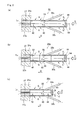
Fig. 2(a) is a schematic view illustrating a mixing unit body of a nozzle head of the applicator of the embodiment of the present invention,Fig. 2(b) is a schematic view illustrating another example of the mixing unit body of the nozzle head of the applicator, andFig. 2(c) is a schematic view illustrating still another example of the mixing unit body of the nozzle head of the applicator. -
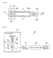
Fig. 3 is a schematic sectional view illustrating the configuration of a mixing unit body of a nozzle head of an applicator of Comparative Example 1. -
Fig. 4 is a schematic view illustrating a measurement device used in a method of measuring the gas flow rate and the resistance in the applicator. - Hereinbelow, an applicator of the present invention will be described in detail on the basis of a preferred embodiment illustrated in the accompanying drawings.
Fig. 1 is a schematic view illustrating the applicator of the embodiment of the present invention. - The
applicator 10 includes anozzle 12 and asheath 14 into which thenozzle 12 is inserted. Thenozzle 12 includes aspray head 20, atubular nozzle body 22 having a base end to which thespray head 20 is connected, and anozzle head 24 which is connected to the tip of thenozzle body 22. - The
spray head 20 is provided with afirst connection section 30a which is connected to afirst syringe 34a and asecond connection section 30b which is connected to asecond syringe 34b. - An
inner tube 32a for feeding a first liquid fed from thefirst syringe 34a to thenozzle head 24 is connected to thefirst connection section 30a. Aninner tube 32b for feeding a second liquid fed from thesecond syringe 34b to thenozzle head 24 is connected to thesecond connection section 30b. - The first
inner tube 32a and the secondinner tube 32b are inserted into thenozzle body 22 and connected to amixing unit body 26 of thenozzle head 24. - The inner diameter of the first
inner tube 32a and the inner diameter of the secondinner tube 32b may be equal to each other or different from each other, and may be appropriately determined depending on the kind and use of liquid to be used. The connection configuration of the firstinner tube 32a and the secondinner tube 32b to themixing unit body 26 will be described below in detail. - The
first syringe 34a and thesecond syringe 34b respectively have apusher 35a and apusher 35b (not illustrated inFig. 1 , refer toFig. 4 ). Thepushers pressing unit 36. The first liquid and the second liquid are fed to thenozzle head 24 by pressing thepushers pressing unit 36. - A syringe having a common configuration can be used as the
first syringe 34a and thesecond syringe 34b. For example, a syringe described inJP 2009-131590 A JP 2009-226189 A pressing unit 36 is not particularly limited to any configuration, and may be automatic or manual as long as it is capable of pressing thepushers - The
first syringe 34a, thesecond syringe 34b, and the pressingunit 36 constitute a liquid feed unit. - As the first liquid filled in the
first syringe 34a and the second liquid filled in thesecond syringe 34b, a combination of liquids which gel when mixed together is used. For example, a combination of an antiadhesive material and a biological tissue adhesive is used. The combination of the first liquid and the second liquid is appropriately selected depending on, for example, the use and intended purpose of theapplicator 10, and case. The gelling of the mixture of the first liquid and the second liquid (hereinbelow, referred to as "liquid mixture") enables the liquid mixture to reliably remain in a target region to which the liquid mixture is applied. - The
spray head 20 is provided with aport 23 which communicates with thenozzle body 22. Agas feed unit 38 is connected to theport 23 through atube 37. - The
gas feed unit 38 is used for feeding gas G in an aseptic condition to thenozzle head 24 through thenozzle body 22 serving as a gas flow passage at a predetermined gas flow rate to jet a liquid mixture Lc. The configuration of thegas feed unit 38 is not particularly limited to any configuration, and one used in a conventional applicator may be appropriately used. For example, thegas feed unit 38 is provided with a gas cylinder which is filled with the gas G, a valve which controls the feed/stoppage of the gas G, a flow meter which measures the flow rate of the gas G, and a regulator which regulates the feed pressure of the gas G. The gas flow rate of the gas G is, for example, 1 to 2 L/min. Such a flow rate enables the liquid mixture Lc to be jetted in a mist form. The gas G is desirably air or nitrogen. - The
nozzle body 22 and thenozzle head 24 are relatively movably inserted into thesheath 14 along the longitudinal direction thereof. Thenozzle body 22 includes, for example, a hollow stainless shaft. Thesheath 14 includes, for example, a long tubular body made of polyethylene whose opposite ends are open. Aclearance 14d between thesheath 14 and thenozzle body 22 functions as an exhaust passage. Gas from atip 14b of thesheath 14 passes through theclearance 14d and is discharged to the outside through arear end 14c of thesheath 14. - The
nozzle head 24 is used for jetting the liquid mixture Lc to the outside from atip 24a together with the gas G. The mixingunit body 26 and atip member 27 which has anopening 27a are disposed inside thenozzle head 24. - In the following description, in the
mixing unit body 26, a side facing thetip 24a of thenozzle head 24 is referred to as a tip side, and a side opposite to thetip 24a of thenozzle head 24 is referred to as a rear end. - The
tip member 27 is disposed on the tip side of themixing unit body 26. Thetip member 27 is attached to thetip 24a of thenozzle head 24. Theopening 27a of thetip member 27 corresponds to an opening of thenozzle head 24. Thetip member 27 includes, for example, stainless steel. Thetip member 27 may be integrated with thenozzle head 24. - In the
mixing unit body 26, for example, the first liquid and the second liquid fed thereto are mixed together and stirred for gelling. - The mixing
unit body 26 includes, for example, a tubular gas permeable member, that is, a gas permeable tube. The gas permeable tube is permeable to gas, but impermeable to liquid. The gas permeable tube is formed of, for example, a hydrophobic material. Specifically, a porous tube made of polytetrafluoroethylene (PTFE) is used. - The mixing
unit body 26 has aconfluent section 40, a stirringsection 42, and a gas introduction section 44 (hereinbelow, also merely referred to as the introduction section 44). - The
confluent section 40 is a region in which the first liquid fed through the firstinner tube 32a and the second liquid fed through the secondinner tube 32b join together. The firstinner tube 32a and the secondinner tube 32b are connected to aperipheral face 29 of theconfluent section 40 at positions that are symmetric with respect to an axis C of themixing unit body 26 in the longitudinal direction, that is, in an axial direction D. - The first
inner tube 32a and the secondinner tube 32b are preferably connected to the peripheral face such that respective ends thereof are flush with the inner face of themixing unit body 26. This prevents or reduces convection of the first liquid and the second liquid in theconfluent section 40 and prevents or reduces stagnation of the first liquid and the second liquid in theconfluent section 40. - The stirring
section 42 is a region in which the first liquid and the second liquid are stirred for gelling using the gas G at least from either the periphery or the rear end side. The stirringsection 42 is located on the tip side of theconfluent section 40 and provided between theconfluent section 40 and thetip member 27. - The
introduction section 44 is a region for allowing the gas G passing through thenozzle body 22 to permeate into themixing unit body 26, and feeding the gas G from the rear end side of theconfluent section 40 of the liquids and allowing the gas G to flow in the axial direction D with respect to theconfluent section 40 to move the liquid mixture Lc and the first liquid and the second liquid in an unmixed state inside the mixingunit body 26 to the tip side so as to be discharged through theopening 27a. Theintroduction section 44 is located on the rear end side of theconfluent section 40. - An end on the rear end side of the
introduction section 44 is sealed by a sealingsection 46. The gas G cannot pass through the sealingsection 46. The configuration of the sealingsection 46 is not particularly limited to any configuration. - The gas G that has passed through the
mixing unit body 26 is turned into micro bubbles in the liquid mixture Lc inside the mixingunit body 26, so that a uniform liquid mixture Lc can be obtained. - In the
applicator 10, the gas G flows into theconfluent section 40 and the stirringsection 42 in the above manner to mix the first liquid and the second liquid together and stir the first liquid and the second liquid for gelling during the jetting of the liquid mixture Lc. Further, the liquid mixture Lc is jetted through theopening 27a of thetip member 27 together with the gas G. - During the jetting, the gas G is continuously fed at a predetermined gas flow rate, and flow in the axial direction D is generated in the
confluent section 40 by the gas G flowing into theconfluent section 40 from the rear end side thereof. The flow in the axial direction D pushes out the entire flow passage in a direction perpendicular to the axial direction D of themixing unit body 26. The first liquid and the second liquid are moved toward the tip side and discharged to the outside through theopening 27a by the flow in the axial direction D. - When the feed of the first liquid and the second liquid is stopped, the first liquid and the second liquid in an unmixed state and the liquid mixture Lc remaining inside the mixing
unit body 26 are moved toward the tip side and discharged to the outside through theopening 27a by the flow of the gas G in the axial direction D from the rear end side. This prevents the remaining of the first liquid and the second liquid in an unmixed state and the liquid mixture Lc. - On the other hand, in the configuration of a nozzle illustrated in Fig. 19 of
JP 2009-131590 A mixing unit body 100 illustrated inFig. 3 (described below), although the gas G is fed to a confluent section from the periphery, the gas G is not fed thereto from the rear end side. Thus, liquid in the confluent section is not pushed out toward the tip side, and may remain in the confluent section. - In the
applicator 10, the liquid mixture Lc can be reliably jetted from thetip 24a of thenozzle head 24 by the operation of thepressing unit 36. Further, even when the liquid mixture Lc is jetted once and then again jetted after a predetermined time, clogging does not occur. Thus, even when the liquid mixture Lc is repeatedly and intermittently jetted, a reduction in the flow rate of the gas G is prevented. Further, it is possible to prevent an increase in the sliding resistance of thepressing unit 36, that is, an increase in force required for pushing out the liquid mixture Lc from the liquid feed unit. Furthermore, since a reduction in the gas flow rate of the gas G is prevented, mixing failure between the first liquid and the second liquid can also be prevented. Thus, even when the liquid mixture Lc is intermittently jetted, a liquid mixture with an appropriate mixture ratio can be jetted at a constant jetting amount. - In the present embodiment, the configuration of the
mixing unit body 26 of thenozzle head 24 is not limited to the configuration illustrated inFig. 2(a) . For example, as in amixing unit body 26a illustrated inFig. 2(b) , aconfluent section 40, a stirringsection 42, and anintroduction section 44 may include separate members. The mixingunit body 26a illustrated inFig. 2(b) has a configuration similar to the configuration of themixing unit body 26 ofFig. 2(a) except that theconfluent section 40 is impermeable to the gas G. Thus, detailed description thereof will be omitted. - In the
mixing unit body 26a illustrated inFig. 2(b) , for example, theconfluent section 40 includes a gas impermeable tubularconfluent member 50, the stirringsection 42 includes a gas permeabletubular stirring member 52, and theintroduction section 44 includes a gas permeabletubular introduction member 54. A sealingsection 46 is formed on the rear end of theintroduction member 54 which constitutes theintroduction section 44. The gas impermeableconfluent member 50 is made of a material having a lower gas permeability than the gas permeable members, for example, resin such as vinyl chloride. The gaspermeable stirring member 52 and the gaspermeable introduction member 54 include, for example, gas permeable tubes which are the same as themixing unit body 26. - In the
mixing unit body 26a, the first liquid and the second liquid fed to theconfluent section 40 are mixed together, and mixed and stirred for gelling by gas G flowing into the stirringsection 42 in the same manner as in themixing unit body 26. Further, the liquid mixture Lc and the like in theconfluent section 40 are allowed to flow toward the tip side by gas G flowing from theintroduction section 44. Accordingly, the liquid mixture Lc is jetted from thetip 24a of thenozzle head 24 in the same manner as in themixing unit body 26 illustrated inFig. 2(a) . In addition, the liquid mixture Lc is prevented from remaining inside the mixingunit body 26. Thus, even when the liquid mixture Lc is repeatedly and intermittently jetted as described above, a reduction in the flow rate of the gas G is prevented. Further, it is possible to prevent an increase in the sliding resistance of thepressing unit 36, that is, an increase in resistance required for feeding the liquid mixture Lc to a target region. - Further, the mixing unit body may have the configuration of a
mixing unit body 26b illustrated inFig. 2(c) . The mixingunit body 26b illustrated inFig. 2(c) has a configuration similar to the configuration of themixing unit body 26 ofFig. 2(a) except that anintroduction section 44 is shorter than theintroduction section 44 of themixing unit body 26 illustrated inFig. 2(a) and apermeable film section 48 which is permeable to the gas G is provided instead of the sealingsection 46 disposed on the rear end of theintroduction section 44. Thus, detailed description thereof will be omitted. - The configuration of the
permeable film section 48 is not particularly limited to any configuration as long as it is permeable to the gas G. For example, at least one hole for allowing the gas G to pass therethrough may be provided. The size, the position, and the number of holes for allowing the gas G to pass therethrough are appropriately determined in advance by, for example, an experiment so as to prevent the liquid mixture Lc and the like from remaining inside the mixingunit body 26b. - In the
mixing unit body 26b illustrated inFig. 2(c) , the first liquid and the second liquid fed to aconfluent section 40 are mixed with gas G flowing into theconfluent section 40 and a stirredsection 42 and stirred. Further, the liquid mixture Lc in theconfluent section 40 is allowed to flow toward the tip side and discharged by gas G flowing from the end of theintroduction section 44. - Accordingly, the liquid mixture Lc is jetted from the
tip 24a of thenozzle head 24 in the same manner as in themixing unit body 26 illustrated inFig. 2(a) . In addition, the liquid mixture Lc is prevented from remaining inside the mixingunit body 26. Thus, even when the liquid mixture Lc is repeatedly and intermittently jetted as described above, a reduction in the flow rate of the gas G is prevented. Further, it is possible to prevent an increase in the sliding resistance of thepressing unit 36, that is, an increase in resistance required for feeding the liquid mixture Lc to a target region. - In the
mixing unit body 26b illustrated inFig. 2(c) , for example, theconfluent section 40 may be made of a material having a lower gas permeability than the gas permeable members, for example, vinyl chloride as with themixing unit body 26a illustrated inFig. 2(b) . Also in this case, an effect similar to the effect of themixing unit body 26 illustrated inFig. 2(a) can be obtained. - In the
confluent section 40, the first liquid and the second liquid may be mixed together in addition to the confluence. - Further, in any of the mixing unit bodies, the
tip member 27 may be directly connected to theconfluent section 40 without providing the stirringsection 42. In this case, the liquids are allowed to join together and further mixed in theconfluent section 40 and the liquid mixture Lc is jetted through theopening 27a of thetip member 27. - The
applicator 10 of the present embodiment can be used in laparoscopic surgery and abdominal surgery. Theapplicator 10 is capable of applying, for example, an antiadhesive material and a biological tissue adhesive to a target region such as organs and the abdominal wall. - The
applicator 10 is inserted into the abdominal cavity through a trocar previously placed on the abdominal wall. - As the trocar, various known trocars used in laparoscopic surgery can be used. For example, a trocar tube disclosed in
Fig. 1 ofJP 2009-226189 A - Further, in the
applicator 10, thenozzle head 24 may have a curved configuration. In this case, for example, thesheath 14 restricts the shape of the curved part of thenozzle head 24, and an antiadhesive material or a biological tissue adhesive can be applied to a target region with thenozzle head 24 curved. - The present invention is basically configured in the above manner. In the above, the applicator of the present invention has been described in detail. However, it is needless to say that the present invention is not limited to the above embodiment and various improvements and modifications may be made without departing from the gist of the invention.
- Hereinbelow, the effect of the applicator of the present invention will be more specifically described. The applicator of the present invention is not limited to an example described below.
- In the present example, in order to confirm the effect of the applicator of the present invention, applicators of Example 1 and Comparative Example 1 provided with nozzle heads having different structures (described below in detail) were manufactured, and the gas flow rate and resistance required for spraying were measured in each of the applicators of Example 1 and Comparative Example 1. The result of the measurement is shown in Table 1.
- First, Example 1 and Comparative Example 1 will be described.
- Example 1 has a configuration similar to the
applicator 10 illustrated inFig. 1 having the mixingunit body 26 illustrated inFig. 2(a) . Thus, detailed description of Example 1 will be omitted. A cylindrical gas permeable PTFE tube having a total length of 35 mm is used as themixing unit body 26. The attachment positions of the firstinner tube 32a and the secondinner tube 32b are 15 mm from the tip in the axial direction D of themixing unit body 26. - In the applicator of Example 1, the length of the
nozzle body 22 is 30 cm, the outer diameter of thenozzle body 22 is 3.7 mm, and the inner diameter of thesheath 14 is 4.5 mm. Further, air is used as the gas. - The applicator of Comparative Example 1 has a nozzle having a configuration similar to the configuration illustrated in Fig. 19 of Patent Literature 1, specifically, has a
mixing unit body 100 of a nozzle head having a configuration illustrated inFig. 3 . Except for this point, the configuration of the applicator of Comparative Example 1 is similar to the configuration of the applicator of Example 1. Thus, for Comparative Example 1, the configuration of themixing unit body 100 will be described in detail and detailed description of the other configurations will be omitted. - A cylindrical gas permeable PTFE tube having a total length of 35 mm is used as the
mixing unit body 100 of Comparative Example 1 illustrated inFig. 3 . Atip member 27 is connected to the tip of themixing unit body 100. A firstinner tube 32a and a secondinner tube 32b are connected to an opening on the rear end of themixing unit body 100. - In Comparative Example 1, a first liquid and a second liquid are fed from the rear end of the
mixing unit body 100. The first liquid and the second liquid are mixed together and stirred by gas G flowing into a confluent section of the first liquid and the second liquid from aperipheral face 100a of themixing unit body 100, and jetted as a liquid mixture Lc through anopening 27a of thetip member 27. - Next, a measurement device used in measurement of the gas flow rate and the resistance required for spraying and a method of measuring the gas flow rate and the resistance in the present example will be described.
-
Fig. 4 is a schematic view illustrating the measurement device used in the method of measuring the gas flow rate and the resistance in the applicator. InFig. 4 , part of theapplicator 10 is not illustrated. - The
measurement device 110 illustrated inFig. 4 includes anautograph 112, agas flow meter 114, aregulator 116, and agas feed unit 118. - The
applicator 10 is attached to theautograph 112 by fixing thesyringes jig 120. - The
autograph 112 pushes thepusher 35a of thesyringe 34a and thepusher 35b of thesyringe 34b through a rod-like jig 122 (hereinbelow, referred to as the pushing jig 122) and records a force generated during the pushing as the resistance. When a gel liquid mixture is present inside the nozzle head, that is, when the nozzle head is clogged, the gel liquid mixture becomes resistance when thepushers - The
gas feed unit 118 is connected to theport 23 of theapplicator 10 through thegas flow meter 114 and theregulator 116. The gas flow rate in thegas flow meter 114 is defined as the gas flow rate of the applicator. When a gel liquid mixture is present inside the nozzle head, that is, the nozzle head is clogged, the gas flow rate also decreases from an initially set gas flow rate. Thus, a change in the gas flow rate from the set gas flow rate is an index which indicates the degree of clogging. - A precision universal tester (AG-X 1kN (model) manufactured by SHIMADZU CORPORATION) was used as the
autograph 112. A flow meter (8500MM-0-1-1 (model) manufactured by KOJIMA INSTRUMENTS INC.) was used as theflow meter 114. Thegas feed unit 118 is a gas cylinder filled with air. - Hereinbelow, the method of measuring the gas flow rate and the sliding resistance in the applicator will be described.
- First, 3.6 ml of distilled water was dropped into powder A using a micropipette, and thereafter sufficiently stirred to dissolve the powder A. Further, 1.55 ml of distilled water was dropped into powder B using a micropipette, and thereafter sufficiently stirred to dissolve the powder B.
- As the powder A, powder of 1.25 g of NHS dextrin and 1.25 g of trehalose was used. As the power B, power of 0.042 g of sodium bicarbonate and 0.11 g of sodium carbonate was used.
- After the dissolving, a solution of the powder A and a solution of the powder B were respectively filled into the
syringe 34a and thesyringe 34b. After the filling, a priming operation was performed to remove air inside thesyringes - Then, a check valve was attached to the tip of each of the
syringes syringes autograph 112 through the fixingjig 120. - Then, the
gas flow meter 114 was connected to theport 23, and theregulator 116 and thegas feed unit 118 were further connected thereto. - The pushing
jig 122 was attached to a load cell of theautograph 112, and lowered until the pushingjig 122 makes contact with thepushers - Then, the pressure of gas from the
gas feed unit 118 was regulated by theregulator 116 to set the gas flow rate at 1.5 L/min. - Then, the
pushers autograph 112 to perform a priming operation. - After the priming operation, the gas flow rate was measured. Then, the
pushers - After the
pushers jig 122 was released from thepushers jig 122 was again brought into contact with thepushers pushers - After the second measurement, the pushing
jig 122 was released from thepushers - Then, the pushing
jig 122 was released from thepushers jig 122 was released from thepushers jig 122 released from thepushers [Table 1] Number of spray times Gas flow rate (l/min) Resistance (n) Example 1 1 1.51 27.15 2 1.51 26.93 3 1.49 27.46 4 1.52 27.12 5 1.49 27.03 Comparative Example 1 1 1.25 30.71 2 1.19 32.50 3 1.13 36.52 4 1.06 39.36 5 0.84 40.57 - As shown in Table 1, in Example 1, even when the spraying is repeatedly performed five times, the gas flow rate hardly changes from the set gas flow rate (1.5 L/min). In Example 1, there is also little change in the resistance even when the spraying is repeatedly performed five times.
- On the other hand, in Comparative example 1, when the spraying is repeatedly performed five times, the gas flow rate decreases from the set gas flow rate (1.5 L/min) in each time. Further, when the spraying is repeatedly performed five times, the resistance increases in each time.
- The result shows that, in the configuration of the present invention, clogging is not caused by the liquid mixture even when the liquid mixture is intermittently sprayed.
-
- 10
- applicator
- 12
- nozzle
- 14
- sheath
- 20
- spray head
- 22
- nozzle body
- 24
- nozzle head
- 26, 26a, 26b, 100
- mixing unit body
- 30b
- second connection section
- 30a
- first connection section
- 34a
- first syringe
- 34b
- second syringe
- 36
- pressing unit
- 38
- gas feed unit
- 40
- confluent section
- 42
- stirring section
- 44
- introduction section
- 46
- sealing section
- 48
- permeable film section
- 50
- confluent member
- 52
- stirring member
- 54
- introduction member
- 110
- measurement device
- Lc
- liquid mixture
Claims (7)
- An applicator comprising:a nozzle including a nozzle head located at a tip thereof and an inner part to which gas is fed;at least two inner tubes inserted into the nozzle and used for feeding at least two kinds of liquids that gel when mixed together to the nozzle head; anda liquid feed unit feeding each of the liquids to each of the inner tubes, whereinthe nozzle head includes a mixing unit body to which the inner tubes are connected and inside which the liquids are allowed to join and mixed together and an opening formed on a tip side of the mixing unit body and used for jetting a liquid mixture of the liquids together with the gas, andthe gas is fed from at least a rear end side with respect to a confluent section in which the liquids join together in the mixing unit body.
- The applicator according to claim 1, wherein the mixing unit body is provided with a gas introduction section which allows the gas to pass therethrough and feeds the gas to the confluent section from at least the rear end side, the gas introduction section being located on the rear end side of the confluent section.
- The applicator according to claim 1 or 2, wherein the mixing unit body is further provided with a stirring section which allows the gas to pass therethrough and at least stirs the liquid mixture, the stirring section being located between the confluent section and the opening.
- The applicator according to any one of claims 1 to 3, wherein the gas introduction section includes a tubular gas permeable member and an end on the rear end side of the gas introduction section is sealed.
- The applicator according to any one of claims 1 to 4, wherein the gas introduction section includes a member having at least one hole formed for allowing the gas to pass therethrough.
- The applicator according to any one of claims 1 to 5, wherein the confluent section includes a tubular member, and the inner tubes are connected to a peripheral face of the confluent section at positions symmetric with respect to an axis in a longitudinal direction.
- The applicator according to any one of claims 1 to 6, wherein the confluent section is formed of a material having a lower gas permeability than the gas permeable member.
Applications Claiming Priority (1)
| Application Number | Priority Date | Filing Date | Title |
|---|---|---|---|
| PCT/JP2013/050298 WO2014109031A1 (en) | 2013-01-10 | 2013-01-10 | Applicator |
Publications (2)
| Publication Number | Publication Date |
|---|---|
| EP2944277A1 true EP2944277A1 (en) | 2015-11-18 |
| EP2944277A4 EP2944277A4 (en) | 2016-10-12 |
Family
ID=51166701
Family Applications (1)
| Application Number | Title | Priority Date | Filing Date |
|---|---|---|---|
| EP13871287.2A Ceased EP2944277A4 (en) | 2013-01-10 | 2013-01-10 | Applicator |
Country Status (3)
| Country | Link |
|---|---|
| EP (1) | EP2944277A4 (en) |
| JP (1) | JP6095693B2 (en) |
| WO (1) | WO2014109031A1 (en) |
Cited By (3)
| Publication number | Priority date | Publication date | Assignee | Title |
|---|---|---|---|---|
| EP3225173A1 (en) * | 2016-03-31 | 2017-10-04 | Terumo Kabushiki Kaisha | Applicator |
| WO2023187528A1 (en) * | 2022-03-31 | 2023-10-05 | Ethicon, Inc. | Sealant applicators having mixing and spraying assemblies with malleable sections |
| US12220118B2 (en) | 2022-03-31 | 2025-02-11 | Ethicon, Inc. | Systems, devices and methods for reconstituting therapeutic powders, mixing precursor solutions, and expressing sealants for controlling bleeding and sealing fluid and air leaks |
Family Cites Families (8)
| Publication number | Priority date | Publication date | Assignee | Title |
|---|---|---|---|---|
| WO1996039212A2 (en) * | 1995-06-06 | 1996-12-12 | Quantic Biomedical Partners | Wound sealant preparation and application device and method |
| JP3024765U (en) * | 1995-11-17 | 1996-05-31 | 株式会社八光電機製作所 | Two chemical mixture spray nozzle |
| US20030209612A1 (en) * | 2000-07-17 | 2003-11-13 | Kevin Hahnen | Spray head for applying a multi-component mixture |
| WO2007059801A1 (en) * | 2005-11-22 | 2007-05-31 | Omrix Biopharmaceuticals S.A. | Applicator device for applying a multi-component fluid |
| JP5147465B2 (en) | 2007-11-08 | 2013-02-20 | テルモ株式会社 | Applicator |
| JP5191288B2 (en) | 2008-02-29 | 2013-05-08 | テルモ株式会社 | Applicator |
| JP5222591B2 (en) * | 2008-03-12 | 2013-06-26 | テルモ株式会社 | Applicator |
| DE102008031415A1 (en) * | 2008-06-27 | 2009-12-31 | Heinrich Burghart Elektro- Und Feinmechanik Gmbh | Flavorful active liquid spraying device for use in e.g. research of sense of taste of person, has compressed gas supply introducing compressed gas into mixing nozzle, where device is designed to discharge and spray active liquid from nozzle |
-
2013
- 2013-01-10 WO PCT/JP2013/050298 patent/WO2014109031A1/en not_active Ceased
- 2013-01-10 JP JP2014556266A patent/JP6095693B2/en active Active
- 2013-01-10 EP EP13871287.2A patent/EP2944277A4/en not_active Ceased
Cited By (5)
| Publication number | Priority date | Publication date | Assignee | Title |
|---|---|---|---|---|
| EP3225173A1 (en) * | 2016-03-31 | 2017-10-04 | Terumo Kabushiki Kaisha | Applicator |
| EP3225172A1 (en) * | 2016-03-31 | 2017-10-04 | Terumo Kabushiki Kaisha | Applicator |
| WO2023187528A1 (en) * | 2022-03-31 | 2023-10-05 | Ethicon, Inc. | Sealant applicators having mixing and spraying assemblies with malleable sections |
| US12114843B2 (en) | 2022-03-31 | 2024-10-15 | Ethicon, Inc. | Sealant applicators having mixing and spraying assemblies with malleable sections and spray tips having reduced dimensions |
| US12220118B2 (en) | 2022-03-31 | 2025-02-11 | Ethicon, Inc. | Systems, devices and methods for reconstituting therapeutic powders, mixing precursor solutions, and expressing sealants for controlling bleeding and sealing fluid and air leaks |
Also Published As
| Publication number | Publication date |
|---|---|
| JP6095693B2 (en) | 2017-03-15 |
| JPWO2014109031A1 (en) | 2017-01-19 |
| EP2944277A4 (en) | 2016-10-12 |
| WO2014109031A1 (en) | 2014-07-17 |
Similar Documents
| Publication | Publication Date | Title |
|---|---|---|
| EP3584005B1 (en) | Bone cement applicator with retractable mixing rod and method for producing a bone cement | |
| DE102015116797B4 (en) | Apparatus and method for storing and mixing a bone cement | |
| JP6636507B2 (en) | Method and apparatus for co-delivery of liquid and powdered hemostats and sealants | |
| US6454739B1 (en) | Fibrin sealant delivery device | |
| US20050209555A1 (en) | Systems and methods for mixing fluids | |
| JPH06209955A (en) | Syringe device | |
| EP2895259B1 (en) | Airless, non-clogging tip assembly and device | |
| EP3584004B1 (en) | Bone cement applicator with retractable mixing rod and method for producing a bone cement | |
| JP2008515594A5 (en) | ||
| PT689874E (en) | DEVICE FOR SPRAYING A MIXTURE OF TWO COMPONENTS | |
| DE102015108783B3 (en) | Device for mixing and storing polymethyl methacrylate bone cement | |
| EP3225173A1 (en) | Applicator | |
| EP3231505A1 (en) | Device for mixing and storing polymethyl methacrylate bone cement with pressure pump and ampoule breaker | |
| CN110753518B (en) | Dual syringe with funnel feed kit | |
| DE102017125592A1 (en) | Powder-liquid bone cement mixer with compressed gas connection | |
| JP6095693B2 (en) | Applicator | |
| JP6799053B2 (en) | Systems, devices, and methods for delivering biomaterials for fracture fixation | |
| US8657481B2 (en) | Systems and methods for mixing fluids | |
| JP2021181082A (en) | Equipment and methods for mixing liquids | |
| US20060133193A1 (en) | High pressure injection system for delivering therapeutic agents having fluid tight connector | |
| WO2015001638A1 (en) | Syringe assembly | |
| US8292846B2 (en) | Applicator tip | |
| EP2826427A1 (en) | Applicator | |
| DE102013214032B4 (en) | Spray applicator for spraying a multi-component fluid | |
| JP5889908B2 (en) | Mixing syringe |
Legal Events
| Date | Code | Title | Description |
|---|---|---|---|
| PUAI | Public reference made under article 153(3) epc to a published international application that has entered the european phase |
Free format text: ORIGINAL CODE: 0009012 |
|
| 17P | Request for examination filed |
Effective date: 20150805 |
|
| AK | Designated contracting states |
Kind code of ref document: A1 Designated state(s): AL AT BE BG CH CY CZ DE DK EE ES FI FR GB GR HR HU IE IS IT LI LT LU LV MC MK MT NL NO PL PT RO RS SE SI SK SM TR |
|
| AX | Request for extension of the european patent |
Extension state: BA ME |
|
| DAX | Request for extension of the european patent (deleted) | ||
| A4 | Supplementary search report drawn up and despatched |
Effective date: 20160913 |
|
| RIC1 | Information provided on ipc code assigned before grant |
Ipc: A61B 17/00 20060101ALI20160907BHEP Ipc: A61B 17/11 20060101AFI20160907BHEP Ipc: B05B 7/04 20060101ALI20160907BHEP |
|
| 17Q | First examination report despatched |
Effective date: 20170608 |
|
| REG | Reference to a national code |
Ref country code: DE Ref legal event code: R003 |
|
| STAA | Information on the status of an ep patent application or granted ep patent |
Free format text: STATUS: THE APPLICATION HAS BEEN REFUSED |
|
| 18R | Application refused |
Effective date: 20181118 |