EP2943402B1 - Access door for possible use with a helicopter fuel tank - Google Patents
Access door for possible use with a helicopter fuel tank Download PDFInfo
- Publication number
- EP2943402B1 EP2943402B1 EP14702091.1A EP14702091A EP2943402B1 EP 2943402 B1 EP2943402 B1 EP 2943402B1 EP 14702091 A EP14702091 A EP 14702091A EP 2943402 B1 EP2943402 B1 EP 2943402B1
- Authority
- EP
- European Patent Office
- Prior art keywords
- access door
- door assembly
- ring
- retaining strip
- fuel tank
- Prior art date
- Legal status (The legal status is an assumption and is not a legal conclusion. Google has not performed a legal analysis and makes no representation as to the accuracy of the status listed.)
- Active
Links
Images
Classifications
-
- B—PERFORMING OPERATIONS; TRANSPORTING
- B64—AIRCRAFT; AVIATION; COSMONAUTICS
- B64D—EQUIPMENT FOR FITTING IN OR TO AIRCRAFT; FLIGHT SUITS; PARACHUTES; ARRANGEMENT OR MOUNTING OF POWER PLANTS OR PROPULSION TRANSMISSIONS IN AIRCRAFT
- B64D37/00—Arrangements in connection with fuel supply for power plant
- B64D37/005—Accessories not provided for in the groups B64D37/02 - B64D37/28
-
- B—PERFORMING OPERATIONS; TRANSPORTING
- B64—AIRCRAFT; AVIATION; COSMONAUTICS
- B64C—AEROPLANES; HELICOPTERS
- B64C1/00—Fuselages; Constructional features common to fuselages, wings, stabilising surfaces or the like
- B64C1/14—Windows; Doors; Hatch covers or access panels; Surrounding frame structures; Canopies; Windscreens accessories therefor, e.g. pressure sensors, water deflectors, hinges, seals, handles, latches, windscreen wipers
- B64C1/1407—Doors; surrounding frames
- B64C1/1446—Inspection hatches
-
- E—FIXED CONSTRUCTIONS
- E06—DOORS, WINDOWS, SHUTTERS, OR ROLLER BLINDS IN GENERAL; LADDERS
- E06B—FIXED OR MOVABLE CLOSURES FOR OPENINGS IN BUILDINGS, VEHICLES, FENCES OR LIKE ENCLOSURES IN GENERAL, e.g. DOORS, WINDOWS, BLINDS, GATES
- E06B7/00—Special arrangements or measures in connection with doors or windows
- E06B7/16—Sealing arrangements on wings or parts co-operating with the wings
-
- Y—GENERAL TAGGING OF NEW TECHNOLOGICAL DEVELOPMENTS; GENERAL TAGGING OF CROSS-SECTIONAL TECHNOLOGIES SPANNING OVER SEVERAL SECTIONS OF THE IPC; TECHNICAL SUBJECTS COVERED BY FORMER USPC CROSS-REFERENCE ART COLLECTIONS [XRACs] AND DIGESTS
- Y02—TECHNOLOGIES OR APPLICATIONS FOR MITIGATION OR ADAPTATION AGAINST CLIMATE CHANGE
- Y02T—CLIMATE CHANGE MITIGATION TECHNOLOGIES RELATED TO TRANSPORTATION
- Y02T50/00—Aeronautics or air transport
- Y02T50/40—Weight reduction
Definitions
- This invention relates generally to access doors.
- Access to particular areas or compartments of a helicopter, aircraft, vehicle or other application may be restricted by an access door.
- an access door may restrict access to a vehicle's fuel tank, which can be subjected to significant pressure during a crash or other traumatic event.
- a properly sealed access door can help insulate the area/compartment housing the fuel tank from the rest of the vehicle and thus help contain any pressure rises or leaks within the area/compartment housing the fuel tank.
- the access door can also permit access to the fuel tank when required, such as during installation or maintenance of the fuel tank system.
- Some access door assemblies include a ring that is bonded to the fuel tank and a door placed above and fixed to the ring using a plurality of fastening members, such as screws or bolts. Securing the fastening members in place axially seals the components of the access door assembly in the direction of the fastening members with the force transmitted by the fastening members. Manually securing each of the fastener members to fix the door relative to the ring is time consuming and takes approximately 10 or so minutes to complete, thus increasing installation and maintenance time. Moreover, use of a screwdriver or other suitable tool to fasten and unfasten the fastener members risks damage to the fuel tank. Further, the closing force and thus the sealing of the assembly can be diminished over the lifetime of the fuel tank as the door assembly is fixed and unfixed by screwing and unscrewing each of the fastener members.
- US6446907 (Wilson Thomas Gray et al ) relates to a helicopter drip pan apparatus for covering and sealing a structural opening in a helicopter.
- the drip pan apparatus includes a frame member adapted to mount to the structural opening of the helicopter.
- the frame member has an inwardly-facing peripheral surface extending around the frame member.
- a drip pan is selectively affixed to the frame member.
- the drip pan includes an outwardly-facing peripheral groove which extends around the outside edge of the drip pan. Like the surface of the frame member, the groove has at least one linear portion.
- the perimeter of the drip pan conforms to the surface of the frame member.
- a seal member is disposed in the groove of the drip pan to sealingly engaging the surface of the frame member against fluid leakage therethrough.
- DE680691 (Arado Egyptianwerke ) relates to a hand hole cover for aircraft components.
- GB2255084 (Aisen Seiki ) relates to a cap assembly for screwing into an opening of a reservoir for storing a fluid therein.
- the sealing member has a sealing portion which extends toward the inner periphery of the opening, and a pair of contacting portions which extend axially toward each inner side of the sealing groove in spaced relationship with each inner side of the sealing groove by a predetermined clearance respectively.
- the sealing member is formed around the periphery thereof with grooves for allowing the sealing portion and contacting portions to be deflected in response to a sliding motion of the sealing member when the cap assembly is screwed into the opening.
- Such access door assemblies may be used in helicopters, aircraft, or any other desired application.
- the access door assemblies may be used to restrict access to fuel tanks or other components, although use of the assemblies is not so limited.
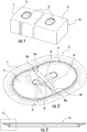
- FIG. 1 illustrates two access door assemblies 10 located on surfaces 13 of two compartments 11.
- the structure with which the access door assembly is used is referred to herein as a compartment, although such term should not be construed as limiting and can reference any suitable enclosure or structure.
- compartment 11 is a fuel tank or houses a fuel tank, but it need not be.
- access door assemblies 10 are configured to restrict access to the interior of a structure, such as compartment 11, and to seal the interior of the compartment 11 or structure from its surroundings.
- FIG 2 illustrates an access door assembly 10 in isolation.
- access door assembly 10 includes a door 12, a ring 14, at least one retaining strip 16, and a seal 20 ( Figure 4 ).
- access door assembly also includes at least one release mechanism 26, a grip 30, and at least one stop 28.
- Access door assembly 10 may have any desired shape and any suitable dimensions.
- door 12 and ring 14 are illustrated as oval-shaped, they are not limited to such a configuration.
- Door 12 and ring 14 may be made of any suitable materials or combination of materials such as, but not limited to, lightweight metal, alloy, high-performance thermoplastic polymer, composites or any suitable combination.
- materials from which door 12 and/or ring 14 may be formed include 2024 aluminum or polyphthalamide (PPA) with electrostatic discharge properties.
- PPA polyphthalamide
- door 12 is assembled with respect to ring 14 such that door 12 is below ring 14 ( i.e., toward the interior of the compartment 11 or other structure). Specifically, at least a portion of a top surface of the door 12 abuts a lower portion of the ring 14 as shown in Figure 4 .
- ring 14 may be assembled with door 12 by inserting door 12 through ring 14 toward the interior of the compartment 11 and then pulling door 12 toward the external surface 13 of compartment 11.
- a grip 30 (shown in Figure 2 ) is included to help assemble door 12 within ring 14 and hoist door 12 into position. If used, grip 30 can be fixed or removable.
- access door assembly 10 does not include a grip at all.
- access door assembly instead includes a cavity that engages with a suitable tool for hoisting door 12 in position with respect to ring 14.
- access door assembly 10 includes a seal 20.
- Seal 20 is positioned within a groove 22 that extends at least partially around a circumference of the access door assembly 10. Groove 22 may extend within either door 12 or ring 14.
- Seal 20 is a radial seal that radially seals door 12 with respect to ring 14 substantially around the entire periphery of the access door assembly 10.
- seal 20 is made of a flexible material such as, but not limited to, rubber (e.g., nitrile (NBR), fluoroelastomer (FKM), etc.) and has a round cross section to help absorb shear resistance, although seal 20 can be made of any suitable material and have any suitable cross section.
- access door assembly 10 includes a shoulder 24 between door 12 and ring 14. Shoulder 24 is configured to absorb the stress/load associated with any pressure changes of the interior of compartment 11 or other suitable structure.
- At least one retaining strip 16 is positioned within a channel of either door 12 or ring 14.
- the at least one retaining strip 16 is configured to absorb any stresses/loads external to the compartment 11 (or other structure) that are acting on the access door assembly 10. In this way, the access door assembly 10's resistance to outer stresses and inner stress are provided by two different mechanisms, the shoulder 24 and the at least one retaining strip 16. As such, the at least one retaining strip 16 is only loaded with a fraction of the stresses applied to the access door assembly 10.
- the at least one retaining strip 16 is made of a harder material than the seal 20 to ensure the at least one retaining strip 16 substantially fills any gap between door 12 and ring 14 when the two are assembled.
- the at least one retaining strip 16 may be made of a thermoplastic polymer such as PEEK or any other suitable material.
- each of retaining strips 16 extends from a release mechanism 26.
- the release mechanism 26 is a pull ring, although release mechanism 26 can have any suitable configuration.
- each of the retaining strips 16 is pushed through a channel until it abuts a stop, such as a stop 28.
- a first retaining strip 16A passes through channel 34 until the retaining strip 16A abuts stop 28A to seal the right half of the access door assembly, while a second retaining strip 16B passes through channel 36 until the retaining strip 16B abuts stop 28B to seal the left half of the access door assembly.
- Abutment of retaining strip 16 with the stop 28 provides an indication that the at least one retaining strip 16 has been properly positioned and the access door system 10 is in its sealed position. This indication enhances the safety of the access door assembly 10 by ensuring that the access door assembly is properly locked/sealed when so desired.
- the access door assembly 10 is referred to as being in a sealed position. When in the sealed position, a tight (in some cases, an air and/or fuel and/or other medium tight) seal is formed between door 12 and ring 14.
- release mechanism 26 includes a lug or other structure 32 that cooperates with any suitable portion (such as but not limited to an aperture of the grip 30) of the access door assembly 10 to maintain the installation position of the release mechanism (and thus maintain the position of the retaining strip 16 within the channel) until the release mechanism is released.
- the retaining strip acts like a pin system.
- the configuration of the access door assembly system described herein eliminates the need for screws, inserts or other fastener members or tools. This reduces the overall weight of the system and simplifies the manufacturing process. Moreover, the time associated with opening and closing the access door assembly is reduced, in turn reducing installation and maintenance time for maintaining any equipment (such as a fuel tank) stored within the compartment of the access door assembly. In some cases, the time required to open and close the access door assembly decreases from approximately 10 minutes to under approximately 2 minutes.
- the configuration of the access door assembly eliminates potential operator error in closing the access door assembly to create a proper seal and thus helps ensure consistent resistance to any pressure surges or leaks experienced in the interior of the compartment or outside the compartment.
- externally applied force is not required to activate and maintain the seal of the access door assembly and thus the mechanical resistance of the locking system of the access door assembly is independent of operator manipulation and outside forces. This is a benefit over prior systems, where external axial forces applied by fastener members created the axial seal.
- the structural integrity of the seal is increased and is less likely to fail.
- the shoulder 24 of door 12 absorbs the inner stresses while the at least one retaining strip 16 absorbs the outer stresses. In this way, the inner stresses are not transmitted to the at least one retaining strip 16 and the outer stresses are not transmitted to the shoulder 24.
Landscapes
- Engineering & Computer Science (AREA)
- Aviation & Aerospace Engineering (AREA)
- Mechanical Engineering (AREA)
- Civil Engineering (AREA)
- Structural Engineering (AREA)
- Gasket Seals (AREA)
- Pressure Vessels And Lids Thereof (AREA)
Description
- This invention relates generally to access doors.
- Access to particular areas or compartments of a helicopter, aircraft, vehicle or other application may be restricted by an access door. As one non-limiting example, an access door may restrict access to a vehicle's fuel tank, which can be subjected to significant pressure during a crash or other traumatic event. A properly sealed access door can help insulate the area/compartment housing the fuel tank from the rest of the vehicle and thus help contain any pressure rises or leaks within the area/compartment housing the fuel tank. The access door can also permit access to the fuel tank when required, such as during installation or maintenance of the fuel tank system.
- Some access door assemblies include a ring that is bonded to the fuel tank and a door placed above and fixed to the ring using a plurality of fastening members, such as screws or bolts. Securing the fastening members in place axially seals the components of the access door assembly in the direction of the fastening members with the force transmitted by the fastening members. Manually securing each of the fastener members to fix the door relative to the ring is time consuming and takes approximately 10 or so minutes to complete, thus increasing installation and maintenance time. Moreover, use of a screwdriver or other suitable tool to fasten and unfasten the fastener members risks damage to the fuel tank. Further, the closing force and thus the sealing of the assembly can be diminished over the lifetime of the fuel tank as the door assembly is fixed and unfixed by screwing and unscrewing each of the fastener members.
- In addition, whether a sufficient axial seal is created between the ring and the door depends in large part on the operator and whether the fastener members are positioned and tightened correctly. Because the fastener members maintain the closure of the door assembly and thus bear the brunt of the inner stresses (stresses from within the area/compartment of the access door assembly) and outer stresses (stresses external to the area/compartment that act on the access door assembly), the axial seal can be compromised and the resistance of the door assembly to both inner and outer stresses can be lowered if the assembly process is not performed correctly. This lowered resistance may not meet applicable resistance to crash standards required for certain uses of the access door.
US6446907 (Wilson Thomas Gray et al ) relates to a helicopter drip pan apparatus for covering and sealing a structural opening in a helicopter. The drip pan apparatus includes a frame member adapted to mount to the structural opening of the helicopter. The frame member has an inwardly-facing peripheral surface extending around the frame member. A drip pan is selectively affixed to the frame member. The drip pan includes an outwardly-facing peripheral groove which extends around the outside edge of the drip pan. Like the surface of the frame member, the groove has at least one linear portion. The perimeter of the drip pan conforms to the surface of the frame member. A seal member is disposed in the groove of the drip pan to sealingly engaging the surface of the frame member against fluid leakage therethrough.DE680691 (Arado Flugzeugwerke ) relates to a hand hole cover for aircraft components.GB2255084 (Aisen Seiki - The terms "invention," "the invention," "this invention" and "the present invention" used in this patent are intended to refer broadly to all of the subject matter of this patent and the patent claims below. Statements containing these terms should be understood not to limit the subject matter described herein or to limit the meaning or scope of the patent claims below. Embodiments of the invention covered by this patent are defined by the claims below, not this summary. This summary is a high-level overview of various aspects of the invention and introduces some of the concepts that are further described in the Detailed Description section below. This summary is not intended to identify key or essential features of the claimed subject matter, nor is it intended to be used in isolation to determine the scope of the claimed subject matter. The subject matter should be understood by reference to appropriate portions of the entire specification of this patent, any or all drawings and each claim.
- Disclosed in this patent are improved access door assemblies. In particular, disclosed are boltless/screwless access door assemblies that include a radial sealing mechanism. Moreover, the component of the access door assembly that absorbs inner stresses of the compartment is separate from the component of the access door assembly that absorbs outer stresses external to the compartment. The access door assembly of the present invention is defined in claim 1.
-
-
Figure 1 is a perspective view of two access door assemblies positioned with respect to two compartments. -
Figure 2 is a perspective view of an access door assembly according to one embodiment. -
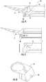
Figure 3 is a cross-section of the access door assembly ofFigure 2 . -
Figure 4 is a close-up view ofFigure 3 , taken at inset B. -
Figure 5 is a cross-sectional view illustrating the ring relative to the door. -
Figure 6 is a perspective view of one embodiment of a release mechanism of the access door assembly ofFigure 2 . - The subject matter of embodiments of the present invention is described here with specificity to meet statutory requirements, but this description is not necessarily intended to limit the scope of the claims. The claimed subject matter may be embodied in other ways, may include different elements or steps, and may be used in conjunction with other existing or future technologies. This description should not be interpreted as implying any particular order or arrangement among or between various steps or elements except when the order of individual steps or arrangement of elements is explicitly described.
- Disclosed herein are improved access door assemblies. Such access door assemblies may be used in helicopters, aircraft, or any other desired application. In some cases, the access door assemblies may be used to restrict access to fuel tanks or other components, although use of the assemblies is not so limited.
-
Figure 1 illustrates twoaccess door assemblies 10 located onsurfaces 13 of twocompartments 11. For simplification, the structure with which the access door assembly is used is referred to herein as a compartment, although such term should not be construed as limiting and can reference any suitable enclosure or structure. In some non-limiting embodiments,compartment 11 is a fuel tank or houses a fuel tank, but it need not be. As mentioned,access door assemblies 10 are configured to restrict access to the interior of a structure, such ascompartment 11, and to seal the interior of thecompartment 11 or structure from its surroundings. -
Figure 2 illustrates anaccess door assembly 10 in isolation. As shown inFigures 2-3 ,access door assembly 10 includes adoor 12, aring 14, at least oneretaining strip 16, and a seal 20 (Figure 4 ). In the embodiment illustrated inFigure 2 , access door assembly also includes at least onerelease mechanism 26, agrip 30, and at least one stop 28.Access door assembly 10 may have any desired shape and any suitable dimensions. For example, althoughdoor 12 andring 14 are illustrated as oval-shaped, they are not limited to such a configuration.Door 12 andring 14 may be made of any suitable materials or combination of materials such as, but not limited to, lightweight metal, alloy, high-performance thermoplastic polymer, composites or any suitable combination. Some non-limiting examples of materials from whichdoor 12 and/orring 14 may be formed include 2024 aluminum or polyphthalamide (PPA) with electrostatic discharge properties. - As shown in
Figures 3-5 ,door 12 is assembled with respect toring 14 such thatdoor 12 is below ring 14 (i.e., toward the interior of thecompartment 11 or other structure). Specifically, at least a portion of a top surface of thedoor 12 abuts a lower portion of thering 14 as shown inFigure 4 . In embodiments wherering 14 is bonded to the interior ofcompartment 11 or other suitable structure,ring 14 may be assembled withdoor 12 by insertingdoor 12 throughring 14 toward the interior of thecompartment 11 and then pullingdoor 12 toward theexternal surface 13 ofcompartment 11. Optionally, a grip 30 (shown inFigure 2 ) is included to help assembledoor 12 withinring 14 and hoistdoor 12 into position. If used,grip 30 can be fixed or removable. In other embodiments,access door assembly 10 does not include a grip at all. In one alternate embodiment, access door assembly instead includes a cavity that engages with a suitable tool for hoistingdoor 12 in position with respect toring 14. - As shown in
Figure 4 ,access door assembly 10 includes aseal 20.Seal 20 is positioned within agroove 22 that extends at least partially around a circumference of theaccess door assembly 10.Groove 22 may extend within eitherdoor 12 orring 14.Seal 20 is a radial seal that radially sealsdoor 12 with respect to ring 14 substantially around the entire periphery of theaccess door assembly 10. In some embodiments, seal 20 is made of a flexible material such as, but not limited to, rubber (e.g., nitrile (NBR), fluoroelastomer (FKM), etc.) and has a round cross section to help absorb shear resistance, althoughseal 20 can be made of any suitable material and have any suitable cross section. - As shown in
Figure 4 ,access door assembly 10 includes ashoulder 24 betweendoor 12 andring 14.Shoulder 24 is configured to absorb the stress/load associated with any pressure changes of the interior ofcompartment 11 or other suitable structure. - In addition, at least one retaining
strip 16 is positioned within a channel of eitherdoor 12 orring 14. The at least one retainingstrip 16 is configured to absorb any stresses/loads external to the compartment 11 (or other structure) that are acting on theaccess door assembly 10. In this way, theaccess door assembly 10's resistance to outer stresses and inner stress are provided by two different mechanisms, theshoulder 24 and the at least one retainingstrip 16. As such, the at least one retainingstrip 16 is only loaded with a fraction of the stresses applied to theaccess door assembly 10. - The at least one retaining
strip 16 is made of a harder material than theseal 20 to ensure the at least one retainingstrip 16 substantially fills any gap betweendoor 12 andring 14 when the two are assembled. The at least one retainingstrip 16 may be made of a thermoplastic polymer such as PEEK or any other suitable material. - In the embodiment shown in
Figure 2 , two retainingstrips 16 are used, although any suitable number of retainingstrips 16 may be used. Each of retainingstrips 16 extends from arelease mechanism 26. As illustrated, therelease mechanism 26 is a pull ring, althoughrelease mechanism 26 can have any suitable configuration. When assembled, each of the retaining strips 16 is pushed through a channel until it abuts a stop, such as a stop 28. For example, in the embodiment illustrated inFigure 2 , afirst retaining strip 16A passes throughchannel 34 until the retainingstrip 16A abuts stop 28A to seal the right half of the access door assembly, while a second retaining strip 16B passes throughchannel 36 until the retaining strip 16B abuts stop 28B to seal the left half of the access door assembly. Abutment of retainingstrip 16 with the stop 28 provides an indication that the at least one retainingstrip 16 has been properly positioned and theaccess door system 10 is in its sealed position. This indication enhances the safety of theaccess door assembly 10 by ensuring that the access door assembly is properly locked/sealed when so desired. When properly sealed, theaccess door assembly 10 is referred to as being in a sealed position. When in the sealed position, a tight (in some cases, an air and/or fuel and/or other medium tight) seal is formed betweendoor 12 andring 14. - Removing the at least one retaining
strip 16 from its channel disengagesdoor 12 fromring 14 and moves theaccess door assembly 10 out of its sealed position and into an open position. Specifically, since the retainingstrip 16 extends from arelease mechanism 26, releasing therelease mechanism 26 from its installation position causes the associated retainingstrip 16 to disengage from its channel, in turn releasing the seal betweendoor 12 andring 14. In some embodiments,release mechanism 26 includes a lug orother structure 32 that cooperates with any suitable portion (such as but not limited to an aperture of the grip 30) of theaccess door assembly 10 to maintain the installation position of the release mechanism (and thus maintain the position of the retainingstrip 16 within the channel) until the release mechanism is released. In this way, the retaining strip acts like a pin system. - The configuration of the access door assembly system described herein eliminates the need for screws, inserts or other fastener members or tools. This reduces the overall weight of the system and simplifies the manufacturing process. Moreover, the time associated with opening and closing the access door assembly is reduced, in turn reducing installation and maintenance time for maintaining any equipment (such as a fuel tank) stored within the compartment of the access door assembly. In some cases, the time required to open and close the access door assembly decreases from approximately 10 minutes to under approximately 2 minutes.
- In addition, the configuration of the access door assembly eliminates potential operator error in closing the access door assembly to create a proper seal and thus helps ensure consistent resistance to any pressure surges or leaks experienced in the interior of the compartment or outside the compartment. In particular, externally applied force is not required to activate and maintain the seal of the access door assembly and thus the mechanical resistance of the locking system of the access door assembly is independent of operator manipulation and outside forces. This is a benefit over prior systems, where external axial forces applied by fastener members created the axial seal.
- Further, because the structure absorbing the inner stresses (stresses acting on the door assembly from within the interior of the compartment) is separate from the structure absorbing the outer stresses (stresses acting on the door assembly external to the compartment), the structural integrity of the seal is increased and is less likely to fail. According to the invention, the
shoulder 24 ofdoor 12 absorbs the inner stresses while the at least one retainingstrip 16 absorbs the outer stresses. In this way, the inner stresses are not transmitted to the at least one retainingstrip 16 and the outer stresses are not transmitted to theshoulder 24. - Different arrangements of the components depicted in the drawings or described above, as well as components and steps not shown or described are possible. Similarly, some features and subcombinations are useful and may be employed without reference to other features and subcombinations. Embodiments of the invention have been described for illustrative and not restrictive purposes, and alternative embodiments will become apparent to readers of this patent. Accordingly, the present invention is not limited to the embodiments described above or depicted in the drawings, and various embodiments and modifications can be made without departing from the scope of the claims below.
Claims (11)
- An access door assembly (10) configured to seal an interior of an aircraft fuel tank (11) from areas external to the fuel tank (11), the access door assembly (10) comprising:(a) a ring (14), configured to be bonded to the interior of the fuel tank, and a door (12);(b) a radial seal (20) that extends substantially around a circumference of the access door assembly (10) and through a groove (22) of the ring (14) or the door (12);(c) a shoulder (24) located between the door (12) and the ring (14) such that at least a portion of a top surface of the door (12) abuts a lower surface of the ring (14) so as to absorb stresses acting on the access door assembly (10) from the interior of the aircraft fuel tank (11); and(d) at least one retaining strip (16) configured to absorb stresses acting on the access door assembly (10) from the area external to the aircraft fuel tank (11);characterised in that:
the door (12) and the ring (14) are assembled to form a channel (34, 36) that is configured to permit the at least one retaining strip (16) to be pushed along the channel (34, 36) to seal the access door assembly (10) and whereby removing the at least one retaining strip (16) from the channel (34, 36) disengages the door (12) from the ring (14). - The access door assembly (10) of claim 1, wherein the radial seal (20) extends around either the ring (14) or the door (12) and has a generally circular cross section.
- The access door assembly (10) of claim 1 or 2, further comprising a stop (28) proximate an end of the channel (34, 36).
- The access door assembly (10) of claim 3, wherein the at least one retaining strip (16) is configured to extend along the channel (34, 36) such that the at least one retaining strip (16) contacts the stop (28).
- The access door assembly (10) of any of the preceding claims, wherein the at least one retaining strip (16) comprises two retaining strips (16A, 16B).
- The access door assembly (10) of any of the preceding claims, wherein the at least one retaining strip (16) is coupled to a release mechanism (26).
- The access door assembly (10) of claim 6, wherein the access door assembly (10) is configured such that release of the release mechanism (26) from an installation position releases the at least one retaining strip (16) from the channel (34, 36) and moves the access door assembly (10) from a sealed position to an open position that provides access to the fuel tank (11).
- The access door assembly (10) of any of the preceding claims, wherein the access door assembly (10) is configured to move between a sealed position and an open position without use of tools.
- The access door assembly (10) of any of the preceding claims, wherein the at least one retaining strip (16) is made of a sufficiently hard material to eliminate gaps between the door (12) and the ring (14), and wherein the sufficiently hard material of the at least one retaining strip (16) is harder than a material of the radial seal (20).
- The access door assembly (10) of any of the preceding claims, wherein the access door assembly (10) further comprises a grip (30).
- The access door assembly of any of the preceding claims , wherein the access door assembly is configured to move to its sealed position without the use of screws or bolts.
Applications Claiming Priority (2)
| Application Number | Priority Date | Filing Date | Title |
|---|---|---|---|
| US201361752071P | 2013-01-14 | 2013-01-14 | |
| PCT/IB2014/058268 WO2014108885A1 (en) | 2013-01-14 | 2014-01-14 | Access door for possible use with a helicopter fuel tank |
Publications (2)
| Publication Number | Publication Date |
|---|---|
| EP2943402A1 EP2943402A1 (en) | 2015-11-18 |
| EP2943402B1 true EP2943402B1 (en) | 2020-02-26 |
Family
ID=50030402
Family Applications (1)
| Application Number | Title | Priority Date | Filing Date |
|---|---|---|---|
| EP14702091.1A Active EP2943402B1 (en) | 2013-01-14 | 2014-01-14 | Access door for possible use with a helicopter fuel tank |
Country Status (4)
| Country | Link |
|---|---|
| US (1) | US9309003B2 (en) |
| EP (1) | EP2943402B1 (en) |
| CA (3) | CA3112649C (en) |
| WO (1) | WO2014108885A1 (en) |
Families Citing this family (1)
| Publication number | Priority date | Publication date | Assignee | Title |
|---|---|---|---|---|
| CN109263852B (en) * | 2018-08-31 | 2022-02-22 | 中国航空工业集团公司沈阳飞机设计研究所 | Aircraft flap fixing device |
Family Cites Families (8)
| Publication number | Priority date | Publication date | Assignee | Title |
|---|---|---|---|---|
| US791779A (en) * | 1904-12-28 | 1905-06-06 | William Heiser | Manhole-door for brewers' or other vats, tanks, casks, &c. |
| DE680691C (en) * | 1938-04-13 | 1939-09-05 | Arado Flugzeugwerke G M B H | Handhole cover for aircraft components |
| US3986635A (en) * | 1975-04-03 | 1976-10-19 | Niskin Shale J | Closure locking and orienting device |
| US4273064A (en) * | 1979-02-01 | 1981-06-16 | Sutton Robert W | Hatch cover |
| US4291816A (en) | 1980-07-09 | 1981-09-29 | Canadair Limited | Fuel tank access door for aircraft |
| FR2492938A1 (en) * | 1980-10-24 | 1982-04-30 | Pont A Mousson | DEVICE FOR FASTENING A COVER ON A BODY, IN PARTICULAR ON A VALVE BODY |
| JPH04327065A (en) * | 1991-04-24 | 1992-11-16 | Aisin Seiki Co Ltd | Seal member in reservoir tank |
| US6446907B1 (en) * | 2000-03-22 | 2002-09-10 | Thomas Gray Wilson | Helicopter drip pan |
-
2014
- 2014-01-14 US US14/154,611 patent/US9309003B2/en active Active
- 2014-01-14 CA CA3112649A patent/CA3112649C/en active Active
- 2014-01-14 WO PCT/IB2014/058268 patent/WO2014108885A1/en not_active Ceased
- 2014-01-14 EP EP14702091.1A patent/EP2943402B1/en active Active
- 2014-01-14 CA CA3112664A patent/CA3112664C/en active Active
- 2014-01-14 CA CA2896717A patent/CA2896717C/en active Active
Non-Patent Citations (1)
| Title |
|---|
| None * |
Also Published As
| Publication number | Publication date |
|---|---|
| CA3112664A1 (en) | 2014-07-17 |
| CA3112664C (en) | 2023-06-13 |
| US9309003B2 (en) | 2016-04-12 |
| EP2943402A1 (en) | 2015-11-18 |
| WO2014108885A1 (en) | 2014-07-17 |
| CA3112649C (en) | 2023-06-13 |
| CA3112649A1 (en) | 2014-07-17 |
| US20140196378A1 (en) | 2014-07-17 |
| CA2896717C (en) | 2021-05-11 |
| CA2896717A1 (en) | 2014-07-17 |
Similar Documents
| Publication | Publication Date | Title |
|---|---|---|
| ES2732231T3 (en) | Systems and methods for use in covering a portion of a fixture that protrudes from a surface | |
| EP2962933B1 (en) | Closing member for opening | |
| EP2441678B1 (en) | Lightning strike protection in aircraft | |
| US20080217479A1 (en) | Window installation method and apparatus | |
| US20120219380A1 (en) | Insulated and sealed cap for a fastener component | |
| EP3225538A1 (en) | Methods and apparatus for forming and installing insulation blankets in a vehicle compartment | |
| US7661626B2 (en) | Window assembly retaining system | |
| US9309003B2 (en) | Access door for possible use with a helicopter fuel tank | |
| US9340274B2 (en) | Impact protection plate for vehicles | |
| US20200332584A1 (en) | Modular, motorized drive system, module, use and production method therefor | |
| EP3037342B1 (en) | Door for closing opening in structure and aircraft | |
| KR101986991B1 (en) | Apparatus for Sealing door of aircraft | |
| WO2012101436A1 (en) | Fastener assembly | |
| US11346492B2 (en) | Fixing system for panels and turbomachine enclosure comprising such system | |
| US20070102580A1 (en) | Window retaining system | |
| US12589855B2 (en) | Window mounting structure for snap and click mounting of a window assembly of an aircraft |
Legal Events
| Date | Code | Title | Description |
|---|---|---|---|
| PUAI | Public reference made under article 153(3) epc to a published international application that has entered the european phase |
Free format text: ORIGINAL CODE: 0009012 |
|
| 17P | Request for examination filed |
Effective date: 20150805 |
|
| AK | Designated contracting states |
Kind code of ref document: A1 Designated state(s): AL AT BE BG CH CY CZ DE DK EE ES FI FR GB GR HR HU IE IS IT LI LT LU LV MC MK MT NL NO PL PT RO RS SE SI SK SM TR |
|
| AX | Request for extension of the european patent |
Extension state: BA ME |
|
| DAX | Request for extension of the european patent (deleted) | ||
| STAA | Information on the status of an ep patent application or granted ep patent |
Free format text: STATUS: EXAMINATION IS IN PROGRESS |
|
| 17Q | First examination report despatched |
Effective date: 20180613 |
|
| REG | Reference to a national code |
Ref country code: DE Ref legal event code: R079 Ref document number: 602014061464 Country of ref document: DE Free format text: PREVIOUS MAIN CLASS: B64C0001140000 Ipc: B64D0037000000 |
|
| GRAP | Despatch of communication of intention to grant a patent |
Free format text: ORIGINAL CODE: EPIDOSNIGR1 |
|
| RIC1 | Information provided on ipc code assigned before grant |
Ipc: B64C 1/14 20060101ALI20190626BHEP Ipc: B64D 37/00 20060101AFI20190626BHEP |
|
| STAA | Information on the status of an ep patent application or granted ep patent |
Free format text: STATUS: GRANT OF PATENT IS INTENDED |
|
| INTG | Intention to grant announced |
Effective date: 20190801 |
|
| RIN1 | Information on inventor provided before grant (corrected) |
Inventor name: PICCO, NICOLAS Inventor name: SANNADI, AMINE |
|
| GRAS | Grant fee paid |
Free format text: ORIGINAL CODE: EPIDOSNIGR3 |
|
| RAP1 | Party data changed (applicant data changed or rights of an application transferred) |
Owner name: SAFRAN AEROSYSTEMS |
|
| GRAA | (expected) grant |
Free format text: ORIGINAL CODE: 0009210 |
|
| STAA | Information on the status of an ep patent application or granted ep patent |
Free format text: STATUS: THE PATENT HAS BEEN GRANTED |
|
| AK | Designated contracting states |
Kind code of ref document: B1 Designated state(s): AL AT BE BG CH CY CZ DE DK EE ES FI FR GB GR HR HU IE IS IT LI LT LU LV MC MK MT NL NO PL PT RO RS SE SI SK SM TR |
|
| REG | Reference to a national code |
Ref country code: GB Ref legal event code: FG4D |
|
| REG | Reference to a national code |
Ref country code: CH Ref legal event code: EP |
|
| REG | Reference to a national code |
Ref country code: AT Ref legal event code: REF Ref document number: 1237343 Country of ref document: AT Kind code of ref document: T Effective date: 20200315 |
|
| REG | Reference to a national code |
Ref country code: IE Ref legal event code: FG4D |
|
| REG | Reference to a national code |
Ref country code: DE Ref legal event code: R096 Ref document number: 602014061464 Country of ref document: DE |
|
| PG25 | Lapsed in a contracting state [announced via postgrant information from national office to epo] |
Ref country code: NO Free format text: LAPSE BECAUSE OF FAILURE TO SUBMIT A TRANSLATION OF THE DESCRIPTION OR TO PAY THE FEE WITHIN THE PRESCRIBED TIME-LIMIT Effective date: 20200526 Ref country code: FI Free format text: LAPSE BECAUSE OF FAILURE TO SUBMIT A TRANSLATION OF THE DESCRIPTION OR TO PAY THE FEE WITHIN THE PRESCRIBED TIME-LIMIT Effective date: 20200226 Ref country code: RS Free format text: LAPSE BECAUSE OF FAILURE TO SUBMIT A TRANSLATION OF THE DESCRIPTION OR TO PAY THE FEE WITHIN THE PRESCRIBED TIME-LIMIT Effective date: 20200226 |
|
| REG | Reference to a national code |
Ref country code: NL Ref legal event code: MP Effective date: 20200226 |
|
| REG | Reference to a national code |
Ref country code: LT Ref legal event code: MG4D |
|
| PG25 | Lapsed in a contracting state [announced via postgrant information from national office to epo] |
Ref country code: HR Free format text: LAPSE BECAUSE OF FAILURE TO SUBMIT A TRANSLATION OF THE DESCRIPTION OR TO PAY THE FEE WITHIN THE PRESCRIBED TIME-LIMIT Effective date: 20200226 Ref country code: GR Free format text: LAPSE BECAUSE OF FAILURE TO SUBMIT A TRANSLATION OF THE DESCRIPTION OR TO PAY THE FEE WITHIN THE PRESCRIBED TIME-LIMIT Effective date: 20200527 Ref country code: BG Free format text: LAPSE BECAUSE OF FAILURE TO SUBMIT A TRANSLATION OF THE DESCRIPTION OR TO PAY THE FEE WITHIN THE PRESCRIBED TIME-LIMIT Effective date: 20200526 Ref country code: SE Free format text: LAPSE BECAUSE OF FAILURE TO SUBMIT A TRANSLATION OF THE DESCRIPTION OR TO PAY THE FEE WITHIN THE PRESCRIBED TIME-LIMIT Effective date: 20200226 Ref country code: LV Free format text: LAPSE BECAUSE OF FAILURE TO SUBMIT A TRANSLATION OF THE DESCRIPTION OR TO PAY THE FEE WITHIN THE PRESCRIBED TIME-LIMIT Effective date: 20200226 Ref country code: IS Free format text: LAPSE BECAUSE OF FAILURE TO SUBMIT A TRANSLATION OF THE DESCRIPTION OR TO PAY THE FEE WITHIN THE PRESCRIBED TIME-LIMIT Effective date: 20200626 |
|
| PG25 | Lapsed in a contracting state [announced via postgrant information from national office to epo] |
Ref country code: NL Free format text: LAPSE BECAUSE OF FAILURE TO SUBMIT A TRANSLATION OF THE DESCRIPTION OR TO PAY THE FEE WITHIN THE PRESCRIBED TIME-LIMIT Effective date: 20200226 |
|
| PG25 | Lapsed in a contracting state [announced via postgrant information from national office to epo] |
Ref country code: CZ Free format text: LAPSE BECAUSE OF FAILURE TO SUBMIT A TRANSLATION OF THE DESCRIPTION OR TO PAY THE FEE WITHIN THE PRESCRIBED TIME-LIMIT Effective date: 20200226 Ref country code: ES Free format text: LAPSE BECAUSE OF FAILURE TO SUBMIT A TRANSLATION OF THE DESCRIPTION OR TO PAY THE FEE WITHIN THE PRESCRIBED TIME-LIMIT Effective date: 20200226 Ref country code: SK Free format text: LAPSE BECAUSE OF FAILURE TO SUBMIT A TRANSLATION OF THE DESCRIPTION OR TO PAY THE FEE WITHIN THE PRESCRIBED TIME-LIMIT Effective date: 20200226 Ref country code: PT Free format text: LAPSE BECAUSE OF FAILURE TO SUBMIT A TRANSLATION OF THE DESCRIPTION OR TO PAY THE FEE WITHIN THE PRESCRIBED TIME-LIMIT Effective date: 20200719 Ref country code: LT Free format text: LAPSE BECAUSE OF FAILURE TO SUBMIT A TRANSLATION OF THE DESCRIPTION OR TO PAY THE FEE WITHIN THE PRESCRIBED TIME-LIMIT Effective date: 20200226 Ref country code: DK Free format text: LAPSE BECAUSE OF FAILURE TO SUBMIT A TRANSLATION OF THE DESCRIPTION OR TO PAY THE FEE WITHIN THE PRESCRIBED TIME-LIMIT Effective date: 20200226 Ref country code: EE Free format text: LAPSE BECAUSE OF FAILURE TO SUBMIT A TRANSLATION OF THE DESCRIPTION OR TO PAY THE FEE WITHIN THE PRESCRIBED TIME-LIMIT Effective date: 20200226 Ref country code: SM Free format text: LAPSE BECAUSE OF FAILURE TO SUBMIT A TRANSLATION OF THE DESCRIPTION OR TO PAY THE FEE WITHIN THE PRESCRIBED TIME-LIMIT Effective date: 20200226 Ref country code: RO Free format text: LAPSE BECAUSE OF FAILURE TO SUBMIT A TRANSLATION OF THE DESCRIPTION OR TO PAY THE FEE WITHIN THE PRESCRIBED TIME-LIMIT Effective date: 20200226 |
|
| REG | Reference to a national code |
Ref country code: AT Ref legal event code: MK05 Ref document number: 1237343 Country of ref document: AT Kind code of ref document: T Effective date: 20200226 |
|
| REG | Reference to a national code |
Ref country code: DE Ref legal event code: R097 Ref document number: 602014061464 Country of ref document: DE |
|
| PLBE | No opposition filed within time limit |
Free format text: ORIGINAL CODE: 0009261 |
|
| STAA | Information on the status of an ep patent application or granted ep patent |
Free format text: STATUS: NO OPPOSITION FILED WITHIN TIME LIMIT |
|
| PG25 | Lapsed in a contracting state [announced via postgrant information from national office to epo] |
Ref country code: AT Free format text: LAPSE BECAUSE OF FAILURE TO SUBMIT A TRANSLATION OF THE DESCRIPTION OR TO PAY THE FEE WITHIN THE PRESCRIBED TIME-LIMIT Effective date: 20200226 |
|
| 26N | No opposition filed |
Effective date: 20201127 |
|
| PG25 | Lapsed in a contracting state [announced via postgrant information from national office to epo] |
Ref country code: PL Free format text: LAPSE BECAUSE OF FAILURE TO SUBMIT A TRANSLATION OF THE DESCRIPTION OR TO PAY THE FEE WITHIN THE PRESCRIBED TIME-LIMIT Effective date: 20200226 Ref country code: SI Free format text: LAPSE BECAUSE OF FAILURE TO SUBMIT A TRANSLATION OF THE DESCRIPTION OR TO PAY THE FEE WITHIN THE PRESCRIBED TIME-LIMIT Effective date: 20200226 |
|
| PG25 | Lapsed in a contracting state [announced via postgrant information from national office to epo] |
Ref country code: MC Free format text: LAPSE BECAUSE OF FAILURE TO SUBMIT A TRANSLATION OF THE DESCRIPTION OR TO PAY THE FEE WITHIN THE PRESCRIBED TIME-LIMIT Effective date: 20200226 |
|
| REG | Reference to a national code |
Ref country code: CH Ref legal event code: PL |
|
| PG25 | Lapsed in a contracting state [announced via postgrant information from national office to epo] |
Ref country code: LU Free format text: LAPSE BECAUSE OF NON-PAYMENT OF DUE FEES Effective date: 20210114 |
|
| REG | Reference to a national code |
Ref country code: BE Ref legal event code: MM Effective date: 20210131 |
|
| PG25 | Lapsed in a contracting state [announced via postgrant information from national office to epo] |
Ref country code: LI Free format text: LAPSE BECAUSE OF NON-PAYMENT OF DUE FEES Effective date: 20210131 Ref country code: CH Free format text: LAPSE BECAUSE OF NON-PAYMENT OF DUE FEES Effective date: 20210131 |
|
| PG25 | Lapsed in a contracting state [announced via postgrant information from national office to epo] |
Ref country code: IE Free format text: LAPSE BECAUSE OF NON-PAYMENT OF DUE FEES Effective date: 20210114 |
|
| PG25 | Lapsed in a contracting state [announced via postgrant information from national office to epo] |
Ref country code: BE Free format text: LAPSE BECAUSE OF NON-PAYMENT OF DUE FEES Effective date: 20210131 |
|
| PG25 | Lapsed in a contracting state [announced via postgrant information from national office to epo] |
Ref country code: HU Free format text: LAPSE BECAUSE OF FAILURE TO SUBMIT A TRANSLATION OF THE DESCRIPTION OR TO PAY THE FEE WITHIN THE PRESCRIBED TIME-LIMIT; INVALID AB INITIO Effective date: 20140114 |
|
| PG25 | Lapsed in a contracting state [announced via postgrant information from national office to epo] |
Ref country code: CY Free format text: LAPSE BECAUSE OF FAILURE TO SUBMIT A TRANSLATION OF THE DESCRIPTION OR TO PAY THE FEE WITHIN THE PRESCRIBED TIME-LIMIT Effective date: 20200226 |
|
| PG25 | Lapsed in a contracting state [announced via postgrant information from national office to epo] |
Ref country code: MK Free format text: LAPSE BECAUSE OF FAILURE TO SUBMIT A TRANSLATION OF THE DESCRIPTION OR TO PAY THE FEE WITHIN THE PRESCRIBED TIME-LIMIT Effective date: 20200226 |
|
| PG25 | Lapsed in a contracting state [announced via postgrant information from national office to epo] |
Ref country code: TR Free format text: LAPSE BECAUSE OF FAILURE TO SUBMIT A TRANSLATION OF THE DESCRIPTION OR TO PAY THE FEE WITHIN THE PRESCRIBED TIME-LIMIT Effective date: 20200226 |
|
| PG25 | Lapsed in a contracting state [announced via postgrant information from national office to epo] |
Ref country code: MT Free format text: LAPSE BECAUSE OF FAILURE TO SUBMIT A TRANSLATION OF THE DESCRIPTION OR TO PAY THE FEE WITHIN THE PRESCRIBED TIME-LIMIT Effective date: 20200226 |
|
| PGFP | Annual fee paid to national office [announced via postgrant information from national office to epo] |
Ref country code: GB Payment date: 20260122 Year of fee payment: 13 |
|
| PGFP | Annual fee paid to national office [announced via postgrant information from national office to epo] |
Ref country code: DE Payment date: 20260120 Year of fee payment: 13 |
|
| PGFP | Annual fee paid to national office [announced via postgrant information from national office to epo] |
Ref country code: IT Payment date: 20260130 Year of fee payment: 13 |
|
| PGFP | Annual fee paid to national office [announced via postgrant information from national office to epo] |
Ref country code: FR Payment date: 20260123 Year of fee payment: 13 |