EP2942672A1 - Media registration method for an image forming device - Google Patents
Media registration method for an image forming device Download PDFInfo
- Publication number
- EP2942672A1 EP2942672A1 EP14167678.3A EP14167678A EP2942672A1 EP 2942672 A1 EP2942672 A1 EP 2942672A1 EP 14167678 A EP14167678 A EP 14167678A EP 2942672 A1 EP2942672 A1 EP 2942672A1
- Authority
- EP
- European Patent Office
- Prior art keywords
- test
- sheet
- holes
- marks
- image
- Prior art date
- Legal status (The legal status is an assumption and is not a legal conclusion. Google has not performed a legal analysis and makes no representation as to the accuracy of the status listed.)
- Withdrawn
Links
- 238000000034 method Methods 0.000 title claims abstract description 29
- 238000012360 testing method Methods 0.000 claims abstract description 123
- 239000000758 substrate Substances 0.000 claims abstract description 38
- 238000004080 punching Methods 0.000 claims abstract description 17
- 230000008569 process Effects 0.000 description 7
- 238000003384 imaging method Methods 0.000 description 6
- 230000009466 transformation Effects 0.000 description 6
- 230000008901 benefit Effects 0.000 description 5
- 238000012937 correction Methods 0.000 description 5
- 238000001514 detection method Methods 0.000 description 4
- 230000000694 effects Effects 0.000 description 4
- 238000005259 measurement Methods 0.000 description 3
- 238000012545 processing Methods 0.000 description 3
- 238000000844 transformation Methods 0.000 description 3
- 238000004458 analytical method Methods 0.000 description 2
- 239000000463 material Substances 0.000 description 2
- 230000009467 reduction Effects 0.000 description 2
- 238000003491 array Methods 0.000 description 1
- 230000001419 dependent effect Effects 0.000 description 1
- 230000012447 hatching Effects 0.000 description 1
- 238000010438 heat treatment Methods 0.000 description 1
- 230000007246 mechanism Effects 0.000 description 1
- 230000001629 suppression Effects 0.000 description 1
- 238000011144 upstream manufacturing Methods 0.000 description 1
Images




Classifications
-
- G—PHYSICS
- G03—PHOTOGRAPHY; CINEMATOGRAPHY; ANALOGOUS TECHNIQUES USING WAVES OTHER THAN OPTICAL WAVES; ELECTROGRAPHY; HOLOGRAPHY
- G03G—ELECTROGRAPHY; ELECTROPHOTOGRAPHY; MAGNETOGRAPHY
- G03G15/00—Apparatus for electrographic processes using a charge pattern
- G03G15/22—Apparatus for electrographic processes using a charge pattern involving the combination of more than one step according to groups G03G13/02 - G03G13/20
- G03G15/23—Apparatus for electrographic processes using a charge pattern involving the combination of more than one step according to groups G03G13/02 - G03G13/20 specially adapted for copying both sides of an original or for copying on both sides of a recording or image-receiving material
- G03G15/231—Arrangements for copying on both sides of a recording or image-receiving material
-
- G—PHYSICS
- G03—PHOTOGRAPHY; CINEMATOGRAPHY; ANALOGOUS TECHNIQUES USING WAVES OTHER THAN OPTICAL WAVES; ELECTROGRAPHY; HOLOGRAPHY
- G03G—ELECTROGRAPHY; ELECTROPHOTOGRAPHY; MAGNETOGRAPHY
- G03G15/00—Apparatus for electrographic processes using a charge pattern
- G03G15/55—Self-diagnostics; Malfunction or lifetime display
-
- G—PHYSICS
- G03—PHOTOGRAPHY; CINEMATOGRAPHY; ANALOGOUS TECHNIQUES USING WAVES OTHER THAN OPTICAL WAVES; ELECTROGRAPHY; HOLOGRAPHY
- G03G—ELECTROGRAPHY; ELECTROPHOTOGRAPHY; MAGNETOGRAPHY
- G03G2215/00—Apparatus for electrophotographic processes
- G03G2215/00362—Apparatus for electrophotographic processes relating to the copy medium handling
- G03G2215/00535—Stable handling of copy medium
- G03G2215/00556—Control of copy medium feeding
- G03G2215/00569—Calibration, test runs, test prints
Definitions
- the invention relates to a media registration method for an image forming device, comprising the steps of:
- media registration is a process of checking, and correcting if necessary, a registration between an image forming device and substrate sheets that are to be used as print media and on which an image is to be formed with the image forming device.
- the registration will relate to different quantities and properties. For example, it will normally have to be checked whether the position of the image forming device in a given direction Z is in registry with the position of the substrate sheets when the latter are fed to a location where an image is formed thereon with the image forming device.
- registration may also relate to the timing at which the image forming device is operated, which time determines the position of the image on the sheet in the direction X.
- Other examples of registration items are a skew angle of the image forming device relative to the media sheets (corresponding to a rotation in the X-Z-plane), and, in case of duplex printing, a front-to-back side registration, i.e. registration between images formed on the front side and the back side of the substrate sheets.
- the registration may also include checks for certain distortions of the image to be formed with the image forming device and/or physical distortions of the substrate sheets, such as expansion or shrinkage in one or two directions due to changes in temperature or humidity, depending upon the material of the substrate sheets.
- the correction of registration errors may involve settings of the sheet supply and alignment system, the timing control of the sheet supply system and/or the image forming device, a physical adjustment of the image forming device and/or a logical adjustment of the image (bitmap) to be printed.
- a skew angle error may be corrected by rotating the image forming device or the bit map.
- substrate sheets which show a certain isotropic or anisotropic thermal expansion, and the image forming process involves heating of the sheets to a known temperature, the thermal expansion that the sheets experience at that temperature may be compensated for by expanding the bit map accordingly.
- a test chart is formed by printing a certain pattern of test marks onto a substrate sheet of the same type as the sheets that will later be used for printing.
- a plurality of identical test charts are printed in order to reduce the effects of measurement noise and tolerances in the sheet handling system and the sheets themselves.
- Both sides of the test charts will be scanned in a duplex scanner, and the positions of the test marks in the scanned images will be compared to the position of at least one physical feature of the substrate sheet (substrate mark) that may serve as a reference. Differences in the positions of the test marks on the front side and the back side relative to the reference will indicate a registration error.
- a natural reference would be provided by the edges of the sheets.
- using the edges of the sheet as a reference is problematic because it requires a scanner that is capable of scanning and recognizing the edges of the sheet.
- the test marks should be printed in close proximity to the reference, i.e. adjacent to the sheet edges. Depending on the type of image forming device, this may not be possible or may have the drawback that parts of the sheet handling system outside of the contour of the sheet are stained with toner or ink.
- the hole can be punched at a safe distance from the edge of the sheet, so that the test marks may also be formed inside the area of the sheet.
- the invention has the advantage that the hole is formed permanently in the sheet, whereas folding always involves the risk that the folded part springs back and returns into the original position when the sheet is placed on the platen of the scanner.
- the contour of the punched hole is exactly the same and equally well detectable when the front side and the back side of the sheet are scanned, which improves in particular the front-to-back side registration.
- the entire stack of test charts may be punched efficiently in a single punching operation, which is not only more convenient for the user but also has the advantage that the punched hole will be formed in all sheets in exactly the same locations.
- a plurality of holes are punched into one sheet, preferably along at least two orthogonal edges of the sheet.
- a conventional office perforator may be used for punching the holes, which permits not only to punch two holes at a time but also has the advantage that the distance between these two holes will exactly correspond to the standardized hole distance for office perforators and is therefore known with high accuracy, which facilitates the analysis of the scanned images.
- the punched holes and the test marks are formed in the same positions, so that the holes will severe the test marks. This assures a high contrast for the detection of the edge of the punched hole.
- the test marks may take the form of plain black squares, with the punched hole being formed inside the square. Then, the corners of the squares permit exact position measurements, and as the corners of the square are located in the direct neighbourhood of the punched holes, the distances to be measured can be very short, which permits an improved accuracy.
- Fig. 1 is a schematic top plan view of an image reproduction system that includes an image forming device 10 and a sheet handling system 12.
- a step (a) the print head 14 of the reproduction system is used for printing a number of test charts 34 in a duplex mode, by forming a pattern of test marks on both sides of each substrate sheet, as will explained in detail below.
- the substrate sheets used for the test charts should be of the same type as those that will later be used for printing.
- Fig. 3 is a view of the front side 46 of one of the test charts 34 that have been printed in step (a), and Fig. 4 shows a view of the back side 48 of the same test chart.
- An identical pattern of test marks 50 has been printed on both the front side 46 and the back side 48 of the test chart.
- the test marks 50 are shaped as black squares with a size of, e.g., 20 x 20 mm and are distributed along all four edges of the test chart. More particularly, a test mark is formed in each of the four corners of the test chart, and two additional test marks are formed at each edge and arranged symmetrically between the two corners that are connected by this edge, and such that all test marks that are disposed along the same edge are aligned with one another.
- the distance between of the outer edge of each test mark 50 and the edge of the test chart 34 may be 4 mm, for example, at all four edges of the test chart.
- Delaying or advancing the timing at which the image is printed will shift the front side image and the back side image in opposite directions.
- the timing will be set such that the edges 64 and 60 coincide, which means that the printed image is precisely centered between the leading edge 62 and the trailing edge 58 of the sheet, and also means that the front side image and the back side image are in perfect registration with one another.
Landscapes
- Physics & Mathematics (AREA)
- General Physics & Mathematics (AREA)
- Accessory Devices And Overall Control Thereof (AREA)
Abstract
A media registration method for an image forming device, comprising the steps of:
(a) printing a number of test charts (34) by forming, with the image forming device, a predetermined pattern of test marks (50) on respective substrate sheets;
(b) forming at least one substrate mark in each of the substrate sheets;
(c) scanning both sides of each test chart (34);
(d) measuring positional relationships between the test marks (50) and the at least one substrate mark of each test chart; and
(e) comparing, for each test chart (34), the positional relationships measured on a front side (46) of the test chart to those measured on a back side,
characterized in that the step (b) includes punching at least one hole (54) through the substrate sheet, and step (d) includes using the punched hole (54) as a substrate mark.
(a) printing a number of test charts (34) by forming, with the image forming device, a predetermined pattern of test marks (50) on respective substrate sheets;
(b) forming at least one substrate mark in each of the substrate sheets;
(c) scanning both sides of each test chart (34);
(d) measuring positional relationships between the test marks (50) and the at least one substrate mark of each test chart; and
(e) comparing, for each test chart (34), the positional relationships measured on a front side (46) of the test chart to those measured on a back side,
characterized in that the step (b) includes punching at least one hole (54) through the substrate sheet, and step (d) includes using the punched hole (54) as a substrate mark.
Description
- The invention relates to a media registration method for an image forming device, comprising the steps of:
- (a) printing a number of test charts by forming, with the image forming device, a predetermined pattern of test marks on respective substrate sheets;
- (b) forming at least one substrate mark in each of the substrate sheets;
- (c) scanning both sides of each test chart;
- (d) measuring positional relationships between the test marks and the at least one substrate mark of each test chart; and
- (e) comparing, for each test chart, the positional relationships measured on a front side of the test chart to those measured on a back side.
- In the image reproduction industry, media registration is a process of checking, and correcting if necessary, a registration between an image forming device and substrate sheets that are to be used as print media and on which an image is to be formed with the image forming device. The registration will relate to different quantities and properties. For example, it will normally have to be checked whether the position of the image forming device in a given direction Z is in registry with the position of the substrate sheets when the latter are fed to a location where an image is formed thereon with the image forming device. In an image forming device where the image is formed while the substrate sheet moves in a direction X (orthogonal to the direction Z) relative to the device, registration may also relate to the timing at which the image forming device is operated, which time determines the position of the image on the sheet in the direction X. Other examples of registration items are a skew angle of the image forming device relative to the media sheets (corresponding to a rotation in the X-Z-plane), and, in case of duplex printing, a front-to-back side registration, i.e. registration between images formed on the front side and the back side of the substrate sheets.
- In a broader sense, the registration may also include checks for certain distortions of the image to be formed with the image forming device and/or physical distortions of the substrate sheets, such as expansion or shrinkage in one or two directions due to changes in temperature or humidity, depending upon the material of the substrate sheets.
- The correction of registration errors may involve settings of the sheet supply and alignment system, the timing control of the sheet supply system and/or the image forming device, a physical adjustment of the image forming device and/or a logical adjustment of the image (bitmap) to be printed. For example, a skew angle error may be corrected by rotating the image forming device or the bit map. Similarly, when substrate sheets are used which show a certain isotropic or anisotropic thermal expansion, and the image forming process involves heating of the sheets to a known temperature, the thermal expansion that the sheets experience at that temperature may be compensated for by expanding the bit map accordingly.
- In a known media registration process, a test chart is formed by printing a certain pattern of test marks onto a substrate sheet of the same type as the sheets that will later be used for printing. Preferably, a plurality of identical test charts are printed in order to reduce the effects of measurement noise and tolerances in the sheet handling system and the sheets themselves. Both sides of the test charts will be scanned in a duplex scanner, and the positions of the test marks in the scanned images will be compared to the position of at least one physical feature of the substrate sheet (substrate mark) that may serve as a reference. Differences in the positions of the test marks on the front side and the back side relative to the reference will indicate a registration error.
- A natural reference would be provided by the edges of the sheets. However, using the edges of the sheet as a reference is problematic because it requires a scanner that is capable of scanning and recognizing the edges of the sheet. Moreover, in order to achieve a high accuracy, the test marks should be printed in close proximity to the reference, i.e. adjacent to the sheet edges. Depending on the type of image forming device, this may not be possible or may have the drawback that parts of the sheet handling system outside of the contour of the sheet are stained with toner or ink.
- It has therefore been proposed to form a reference by folding over one or two corners of each sheet, so that the folded corner will cover a part of a test mark printed at a safe distance from the sheet edges. The edges of the folded corner will then give a high contrast on the background of the printed mark. However, this method is cumbersome because the user is required to manually fold over the corners of all test charts. Moreover, it is problematic that the reference features, i.e., the corners manually folded over, may vary considerably from sheet to sheet and even differ in their appearance on the front side and the back side of the same sheet.
- It is an object of the invention to provide a media registration method that can be carried out more easily and provides an improved accuracy.
- In order to achieve this object, the step (b) of forming at least one substrate mark in each of the substrate sheets comprises punching at least one hole through the substrate sheet, and the step (d) of measuring positional relationships includes using the punched hole as a substrate mark.
- In the method according to the invention, the hole can be punched at a safe distance from the edge of the sheet, so that the test marks may also be formed inside the area of the sheet. In comparison to the known method where the corners of the sheet are folded over, the invention has the advantage that the hole is formed permanently in the sheet, whereas folding always involves the risk that the folded part springs back and returns into the original position when the sheet is placed on the platen of the scanner. Moreover, the contour of the punched hole is exactly the same and equally well detectable when the front side and the back side of the sheet are scanned, which improves in particular the front-to-back side registration.
- It is another a remarkable advantage of the invention that it permits to automatically calibrate the scanner that is used in step (c).
- In the typical case that a plurality of test charts are formed, the entire stack of test charts may be punched efficiently in a single punching operation, which is not only more convenient for the user but also has the advantage that the punched hole will be formed in all sheets in exactly the same locations.
- More specific optional features of the invention are indicated in the dependent claims.
- Preferably, a plurality of holes are punched into one sheet, preferably along at least two orthogonal edges of the sheet.
- A conventional office perforator may be used for punching the holes, which permits not only to punch two holes at a time but also has the advantage that the distance between these two holes will exactly correspond to the standardized hole distance for office perforators and is therefore known with high accuracy, which facilitates the analysis of the scanned images.
- In a preferred embodiment, the punched holes and the test marks are formed in the same positions, so that the holes will severe the test marks. This assures a high contrast for the detection of the edge of the punched hole. In a preferred embodiment, the test marks may take the form of plain black squares, with the punched hole being formed inside the square. Then, the corners of the squares permit exact position measurements, and as the corners of the square are located in the direct neighbourhood of the punched holes, the distances to be measured can be very short, which permits an improved accuracy.
- Embodiment examples will now be described in conjunction with the drawings, wherein;
- Fig. 1
- is a schematic top plan view of an image forming device and a sheet handling mechanism in a printer to which the invention is applicable;
- Fig. 2
- is a symbolic representation of the media registration method according to the invention;
- Figs. 3 and 4
- are a front view and a back view of one of a plurality of test charts to be formed in accordance with the invention;
- Figs. 5 to 7
- are views of the test chart, illustrating a detection of a skew error of a print head;
- Figs. 8 to 11
- are views of the test chart illustrating the detection of the skew error with automatic correction of a skew error of a scanner;
- Fig. 12
- is a view of a test chart illustrating a correction of a shear distortion error of the print head; and
- Fig. 13
- is a view of a test chart illustrating a method of X-direction media registration.
- The present invention will now be described with reference to the accompanying drawings, wherein the same or similar elements are identified with the same reference numeral.
-
Fig. 1 is a schematic top plan view of an image reproduction system that includes animage forming device 10 and asheet handling system 12. - The
image forming device 10 comprises aprint head 14 and acontroller 16. Theprint head 14 extends across the entire width of aconveyer path 18 on whichsubstrate sheets 20 are fed by means of thesheet handling system 12. Thecontroller 16 includes a storage device storing abit map 22 and is arranged to control theprint head 14 such that animage 24 corresponding to thebit map 22 is printed on themedia sheets 20. It is desired that eachimage 24 is in exact registry with thesubstrate sheet 20 on which it is printed. - In the example shown, it is assumed that the
sheet handling system 12 is arranged to feed the substrate sheets past theprint head 14 in a direction X with a fixed and known positioning in a direction Z normal to the direction X and with known timings, and with side edges of the sheets aligned exactly in the direction X. To that end, askew angle detector 26 is disposed at an upstream end of theconveyer path 18 for detecting the skew angle of each arrivingsheet 20. Skewcorrection motors 28 are driven by theskew angle detector 26 so as to rotate each sheet in order to compensate the detected skew angle, so that the side edges of the sheet are aligned with the direction X. Then, aside edge detector 30 detects the Z-position of one of the side edges of the sheet, and aleading edge detector 32 detects the timing when the leading edge of the sheet reaches a predefined X-position. The data detected by theedge detectors controller 16 for translating the data of thebit map 22 into print instructions such that each pixel of the bit map will be printed in the correct position, provided that theprint head 14 is itself aligned correctly relative to thesheet handling system 12 and does not produce any imaging errors. - When the image reproduction system is being prepared for processing a new type of print media, i.e.
substrate sheets 20 in a different format and/or made of a different material, it is advisable to carry out a media registration process in order to check in particular theprint head 14 for correct alignment and for possible imaging errors that might distort the shape of the printedimage 24 and/or its position on the substrate sheet. The basic steps of such a media registration process have been illustrated inFig. 2 . - In a step (a), the
print head 14 of the reproduction system is used for printing a number oftest charts 34 in a duplex mode, by forming a pattern of test marks on both sides of each substrate sheet, as will explained in detail below. The substrate sheets used for the test charts should be of the same type as those that will later be used for printing. - In a subsequent step (b) an
ordinary office perforator 36 is used for punching holes through the entire stack of test charts 34. In this step, the test charts are preferably held in registry with one another and are punched in a condition in which the edges of the test charts abut astop 38 of the perforator and, as a consequence, the at least twopunching tools 40 of the perforator will form the holes at exactly the same distance from the edge of the sheets. - Then, in a step (c), both sides of each
test chart 34 are scanned in aduplex scanner 42, and the scan data are transmitted to an electronicimage processing system 44 where the positions of the test marks relative to the punched holes are measured in a step (d) and then possible registration errors are detected in a step (e) by comparing the results that have been obtained in step (d) for the front side of the test chart to those obtained for the back side. The detected registration errors may then be fed back to the reproduction system for making suitable adjustments for error correction. - In particular, the timings of the print commands sent to the
print head 14 will be adjusted such that theimage 24 will be printed in a position centered between the leading edge and the trailing edge of thesheet 20, as has been symbolized by a double-arrow T inFig. 1 . - Another error that may be detected in step (e) is a skew error of the
print head 14, i.e. the (linear) arrays of printing elements of theprint head 14 are rotated relative to the direction Z, as has been symbolized by a double-arrow S inFig. 1 . This error is preferably compensated by a physical adjustment (rotation) of theprint head 14, whereas other imaging errors of the print head may preferably be compensated by suitable transformations of thebit map 22. -
Fig. 3 is a view of thefront side 46 of one of the test charts 34 that have been printed in step (a), andFig. 4 shows a view of theback side 48 of the same test chart. An identical pattern of test marks 50 has been printed on both thefront side 46 and theback side 48 of the test chart. The test marks 50 are shaped as black squares with a size of, e.g., 20 x 20 mm and are distributed along all four edges of the test chart. More particularly, a test mark is formed in each of the four corners of the test chart, and two additional test marks are formed at each edge and arranged symmetrically between the two corners that are connected by this edge, and such that all test marks that are disposed along the same edge are aligned with one another. The distance between of the outer edge of eachtest mark 50 and the edge of thetest chart 34 may be 4 mm, for example, at all four edges of the test chart. - While all test marks are commonly designated with the
reference numeral 50, specific test marks inFig. 3 have been designated by individual reference signs A, B, C and D. The test marks A und B form a pair and are disposed at a mutual distance that corresponds to the distance between the twopunching tools 40 of theoffice perforator 36 shown inFig. 2 . Apunch mark 52 between the test marks A and B indicates that, in step (b), holes 54 shall be punched within the test marks A and B in a single punching operation of theperforator 36. Similarly, apunch mark 56 between the test marks C and D inFig. 3 indicates that holes 54 within these test marks shall also be formed in a common punching operation (but with a different orientation of the stack oftest charts 34 relative to the perforator). - For most of the operations that will be described below, it is not essential that, when the
holes 54 are punched, the test charts are carefully held with their edge in abutment at thestop 38 shown inFig. 2 . It is sufficient that theholes 54 are formed somewhere within the squares of the test marks 50. For this reason, theholes 54 shown inFig. 3 have slightly different distances from the associated edges of the test chart. - Since the pattern of test marks 50 is identical for the
front side 46 and theback side 48 of the test chart, thesame reference numerals 50 and A-D have also been used for the test marks inFig. 4 . However, since theholes 54 have been punched through the test chart and the image of theback side 48 is the mirror image of the front side 46 (with the Z axis as mirror axis), thehole 54 that is located inside the test mark D inFig. 4 is the identical with the hole that is located inside the test mark C inFig. 3 , and the same applies equivalently to all the other holes and test marks. As a consequence, the positions of theholes 54 relative to their test marks inFig. 4 are not the same as inFig. 3 . - This effect may be utilized for detecting registration errors, as will now be explained in conjunction with
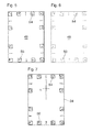
Figs. 5 to 7 (where the hatching of the test marks 50 has been omitted for reasons of clarity).Fig. 5 shows thefront side 46 of a test chart, similarly asFig. 3 but with the difference that, due to a skew error of theprint head 14, the pattern of test marks 50 that has been printed with this print head is slightly rotated (counter-clockwise) relative to the edges of the sheet. However, when the edges of the sheet are not visible, the rotation would hardly be perceptible or detectable. -
Fig. 6 is a view of theback side 48. Due to the skew error of the print head, the pattern of test marks 50 inFig. 6 is rotated in the same direction (counter-clockwise) as inFig. 5 , whereas the pattern ofholes 54 is not rotated but is the mirror image of the pattern shown inFig. 5 . - Now, both
sides scanner 42, by reflecting the image of theback side 48 again at the Z-axis. The result is shown inFig. 7 , where the back side image has been shown in dashed lines as inFig. 6 . It can be seen that there is an exact co-incidence between the positions of theholes 54 in both images, because the two reflections at the Z-axis have cancelled each other. However, considering the test marks 50, the second reflection at the Z-axis has not reversed the rotation but has doubled it, so that the relatively rotated positions of the test marks 50 on the front side and the back side are clearly visible inFig. 7 . - Although the edges of the
test chart 34 have been shown for illustration purposes inFig. 7 , it should be observed that it is not necessary that thescanner 42 is actually capable of scanning and recognizing the edges of the sheet. When the sheet edges are not available, the correct superposition of the two images can still be achieved by moving the two images relative to one another in X-direction and Z-direction until the best fit for the positions of the test marks 50 and theholes 54 is achieved. Then, it is easy to locate the centre of the superposed images and to measure the angle α of relative rotation between the two test mark patterns. The skew error to be corrected will be α/2. - In the above description, it has been assumed that the
scanner 42 was calibrated precisely and did not produce any errors of its own. In a practical scenario, however, this cannot be taken for granted. A precise calibration of a scanner apparatus is time-consuming and costly. It is therefore a great advantage of the invention that it permits to automatically calibrate the scanner, as will now explained by reference toFigs. 8 to 11 . -
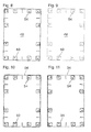
Fig. 8 shows again afront side 46 with the same print head skew error as inFig. 5 . This time, however, the entire image is slightly rotated clockwise, due to a skew error in thescanner 42 which masks the skew errors of the print head.Fig. 9 shows the scanned image of theback side 48 with the same clockwise rotation due to the scanner skew error.Fig. 10 shows theback side 48 reflected back and superposed on the front side in the same way as inFig. 7 . InFig. 10 , it can be observed, however, that the images of theholes 54 do not fit, because the scanner skew errors have not been cancelled but doubled by the reflection. On the other hand, in this example, there is (accidentally) a relatively good fit between the test marks 50. Now, the images of the front side and the back side inFig. 10 are rotated in opposite directions (corresponding to a rotation of the non-reflected image inFig. 9 in the same counter-clockwise direction as the front side image), until the images of theholes 54 coincide. The result is shown inFig. 11 , where, now, the relative rotation of the test marks 50 is clearly visible. This relative rotation indicates the skew error of (only) theprint head 14 which can now be cancelled and eliminated as before. - It should be noted that
Fig. 10 has been shown for illustration purposes only. In practice, the analysis in step (d) will be performed directly by measuring the positions of the test marks 50 (e.g. the positions of the corners of the squares) relative to the positions of theholes 54 which, except for the reflection, are considered to be the same for the front and the back side of the sheet. This will lead directly to the image shown inFig. 11 , i.e. the scanner calibration of the scanner skew error is achieved automatically. Further, the positions of the corners of the squares of the test marks 50 will always be measured relative to the position of thehole 54 that is located inside the test mark, so that the distances to be measured are small and can therefore be determined with high accuracy. - Equivalent procedures may be used for detecting other types of registration error of the
print head 10 and simultaneously eliminating the corresponding scanner calibration errors. - As another example,
Fig. 12 shows an image of thefront side 46 and a superposed reflected image of theback side 48 of atest chart 34 for the case that thescanner 42 has a calibration error that leads to a shear transformation of the images. Due to the reflection of the image of theback side 48, both images are sheared in opposite directions, so that the difference is clearly visible. Measuring the corners of the test marks 50 relative to the respectively associatedholes 54 is in this case equivalent to an inversion of the shear transformations until theholes 54 coincide. By comparing the positions of the test marks 50 on the front side and the back side it may then be decided whether or not theprint head 14 has an imaging error that results in a shear transformation of the image (i.e. only the image of the test marks 50). - Other imaging errors such as an expansion of the image in X-direction, expansion in Z-direction or different expansions in X-direction for the top and bottom parts of the image and/or different expansions in Z-direction for the left and right parts of the image (resulting in a trapezoidal deformation of the image) may be detected analogously, also with automatic suppression of corresponding scanner calibration errors.
- A scanner calibration error that cannot be eliminated in the way described above is an isotropic scaling (enlargement or reduction) of the entire image. This error, however, has no effect on the media registration, anyway.
- In contrast, there may be cases where it is desirable to detect and eliminate a print head imaging error that leads to an isotropic enlargement or reduction of the image, i.e. a scaling of the image relative to the fixed format of the
substrate sheets 20. Such error can also be detected without having to detect the edges of the sheet, e. g. by comparing the almost page-size rectangles that are formed by the overall configuration of the test marks 50 (or the corners thereof) to the approximate rectangle that is formed by the punchedholes 54 along all four edges of the sheet. The accuracy will then depend to some extent upon the accuracy with which the punching process has been performed in step (b). - Another, more accurate detection of scaling errors is possible due to the fact that the distance between two
holes 54 that have been punched in the same punching process, such as the holes in the test marks A and B inFig. 3 is given by the known standard distance between thepunching tools 40 of the perforator. Thus, by comparing the measured distance between theholes 54 in X-direction and in Z-direction to the known punching tool distance, it is possible to determine the actual scaling factors in each direction. - When a distance between two
holes 54 or the position of a corner of atest mark 50 relative to ahole 54 has to be measured, this means of course that the measurement is made by reference to the centre of thecircular hole 54. Image processing algorithms that permit to derive the position of a centre of a circle from the image of the contour of the circle or the entire area of the circle are well known in the art. - Whenever an image forming error or scaling error of the
print head 14 has been detected, this error can preferably be compensated for by performing an inverse transformation on thebit map 22. It should be observed however that identical transformations have to be performed for the bit maps for the front side and the back side, in order to preserve the front-to-back side registration of the images. - Another factor that is important for the front-to-back side registration is the operation represented by the double-arrow T in
Fig. 1 , i.e. the timing of the operation of the print head which determines the position of theimage 24 on thesheet 20 in X-direction. A correct front-to-back side registration is equivalent to placing theimage 24 exactly in the centre between the leading edge and the trailing edge of the sheet. -
Fig. 13 illustrates how this can be achieved in the method according to the invention. Again, the image of the front side (continuous lines) and the reflected image of the back side (dashed lines) of atest chart 34 have been superposed. - When the
test chart 34 was printed, the timing was such that the distance between theleft edge 56 of the test mark A on the front side and the trailingedge 58 of the sheet is larger than the distance between theright edge 60 of the front side test mark in the right corner and the leadingedge 62. It shall be assumed again that theactual edges holes 54 are in registry, the test marks on the back side (dashed lines inFig. 13 ) are the mirror images of the test marks on the front side, and consequently, the position of theright edge 64 of the test mark A on the back side represents the position of theleft edge 56 of the same test mark A on the front side, and the positions of theedges edges leading edge 62 and the trailingedge 58 of the sheet, and also means that the front side image and the back side image are in perfect registration with one another. - Additional information is required for positioning the image 24 (
Fig. 1 ) exactly in the centre of the sheet in Z-direction. This information can be obtained for example by carefully punching the test charts 34 so that the distance Δ between thehole 54 and the side edge of the sheet (see alsoFig. 13 ) is known with sufficient accuracy. Then, centering in Z-direction may be achieved calculating the Z-positions of the side edges of the sheet on the basis of the positions of the test marks 50 and the known distance Δ and by physically adjusting theprint head 14 or logically adjusting thebit map 22 relative to the calculated edge positions.
Claims (11)
- A media registration method for an image forming device (10), comprising the steps of:(a) printing a number of test charts (34) by forming, with the image forming device (10), a predetermined pattern of test marks (50) on respective substrate sheets (20);(b) forming at least one substrate mark in each of the substrate sheets (20);(c) scanning both sides (46, 48) of each test chart (34);(d) measuring positional relationships between the test marks (50) and the at least one substrate mark of each test chart; and(e) comparing, for each test chart (34), the positional relationships measured on a front side (46) of the test chart to those measured on a back side (48),
characterized in that the step (b) includes punching at least one hole (54) through the substrate sheet (20), and step (d) includes using the punched hole (54) as a substrate mark. - The method according to claim 1, wherein the number of test charts (34) is greater than one and the printed test charts (34) are stacked one upon the other and punched in a single punching operation in step (b).
- The method according to claim 1 or 2, wherein the holes (54) are circular.
- The method according to any of the preceding claims, wherein the holes (54) are punched with an office perforator having at least two punching tools (40) arranged in a standard distance.
- The method according to any of the preceding claims, wherein at least two holes (54) are formed along each of two mutually orthogonal edges of the sheet (20).
- The method according to claim 5, wherein at least two holes (54) are formed along each of the four edges of the sheet.
- The method according to claim 6, wherein at least four holes (54) are formed along each edge of the sheet.
- The method according to any of the preceding claims, wherein the test marks (50) are formed by coloured areas, and the holes (54) are formed to be included in or at least to overlap with these areas.
- The method according to claim 8, wherein the test marks (50) have a rectangular shape.
- The method according to claim 9, wherein step (a) comprises printing punch marks (52, 56) on the sheet (20).
- A test chart (34) for use in the method according to any of the preceding claims, the test chart having test marks (50) on both sides (46, 48), characterized in that the test chart has through-holes (54) in positions at or near the test marks (50).
Priority Applications (1)
| Application Number | Priority Date | Filing Date | Title |
|---|---|---|---|
| EP14167678.3A EP2942672A1 (en) | 2014-05-09 | 2014-05-09 | Media registration method for an image forming device |
Applications Claiming Priority (1)
| Application Number | Priority Date | Filing Date | Title |
|---|---|---|---|
| EP14167678.3A EP2942672A1 (en) | 2014-05-09 | 2014-05-09 | Media registration method for an image forming device |
Publications (1)
| Publication Number | Publication Date |
|---|---|
| EP2942672A1 true EP2942672A1 (en) | 2015-11-11 |
Family
ID=50693500
Family Applications (1)
| Application Number | Title | Priority Date | Filing Date |
|---|---|---|---|
| EP14167678.3A Withdrawn EP2942672A1 (en) | 2014-05-09 | 2014-05-09 | Media registration method for an image forming device |
Country Status (1)
| Country | Link |
|---|---|
| EP (1) | EP2942672A1 (en) |
Cited By (3)
| Publication number | Priority date | Publication date | Assignee | Title |
|---|---|---|---|---|
| WO2017183396A1 (en) * | 2016-04-21 | 2017-10-26 | コニカミノルタ株式会社 | Image-forming apparatus and image-forming method |
| CN111716922A (en) * | 2019-03-19 | 2020-09-29 | 富士施乐株式会社 | Printer and printing system |
| US12143552B1 (en) | 2023-11-13 | 2024-11-12 | Ricoh Company, Ltd. | Print scaling correction mechanism |
Citations (5)
| Publication number | Priority date | Publication date | Assignee | Title |
|---|---|---|---|---|
| JP2003173109A (en) * | 2001-12-07 | 2003-06-20 | Konica Corp | Image forming apparatus and image forming adjustment method |
| EP1385119A2 (en) * | 2002-07-24 | 2004-01-28 | Fuji Photo Film Co. Ltd. | Image processing apparatus, and image processing program storage medium |
| EP1613052A2 (en) * | 2004-06-29 | 2006-01-04 | Konica Minolta Business Technologies, Inc. | Image forming apparatus and system, information processing apparatus, image position correcting method, recording media, and program |
| JP2006198804A (en) * | 2005-01-18 | 2006-08-03 | Fuji Photo Film Co Ltd | Misalignment measuring method, misalignment correction device and misalignment correction program |
| EP2228714A2 (en) * | 2009-03-13 | 2010-09-15 | Ricoh Company, Ltd. | Image forming apparatus, image forming method, and computer-readable storage medium |
-
2014
- 2014-05-09 EP EP14167678.3A patent/EP2942672A1/en not_active Withdrawn
Patent Citations (5)
| Publication number | Priority date | Publication date | Assignee | Title |
|---|---|---|---|---|
| JP2003173109A (en) * | 2001-12-07 | 2003-06-20 | Konica Corp | Image forming apparatus and image forming adjustment method |
| EP1385119A2 (en) * | 2002-07-24 | 2004-01-28 | Fuji Photo Film Co. Ltd. | Image processing apparatus, and image processing program storage medium |
| EP1613052A2 (en) * | 2004-06-29 | 2006-01-04 | Konica Minolta Business Technologies, Inc. | Image forming apparatus and system, information processing apparatus, image position correcting method, recording media, and program |
| JP2006198804A (en) * | 2005-01-18 | 2006-08-03 | Fuji Photo Film Co Ltd | Misalignment measuring method, misalignment correction device and misalignment correction program |
| EP2228714A2 (en) * | 2009-03-13 | 2010-09-15 | Ricoh Company, Ltd. | Image forming apparatus, image forming method, and computer-readable storage medium |
Cited By (5)
| Publication number | Priority date | Publication date | Assignee | Title |
|---|---|---|---|---|
| WO2017183396A1 (en) * | 2016-04-21 | 2017-10-26 | コニカミノルタ株式会社 | Image-forming apparatus and image-forming method |
| JPWO2017183396A1 (en) * | 2016-04-21 | 2019-02-28 | コニカミノルタ株式会社 | Image forming apparatus and image forming method |
| CN111716922A (en) * | 2019-03-19 | 2020-09-29 | 富士施乐株式会社 | Printer and printing system |
| CN111716922B (en) * | 2019-03-19 | 2023-02-28 | 富士胶片商业创新有限公司 | Printers and Printing Systems |
| US12143552B1 (en) | 2023-11-13 | 2024-11-12 | Ricoh Company, Ltd. | Print scaling correction mechanism |
Similar Documents
| Publication | Publication Date | Title |
|---|---|---|
| JP6237742B2 (en) | Image processing apparatus and image processing method | |
| EP2882596B1 (en) | Methods and systems for determining a printing position | |
| JP6252577B2 (en) | Image processing apparatus and image processing method | |
| EP2712343B1 (en) | A printer and a method of printing an image in alignment with the edge of a substrate | |
| US20210362518A1 (en) | Lateral adjustment of print substrate based on a camera image | |
| US20180159989A1 (en) | Image forming apparatus and control method of image forming apparatus | |
| US10427435B2 (en) | Printing indicia indicating an intended location of a fold line | |
| US11838454B2 (en) | Inspection apparatus, control method thereof, and storage medium | |
| EP2942672A1 (en) | Media registration method for an image forming device | |
| CN108349624A (en) | Detection dislocation | |
| JP2017228165A (en) | Image processing apparatus, image forming system, and image processing program | |
| EP1370420B1 (en) | Paper tray adjustment page | |
| JP6365053B2 (en) | Image forming apparatus | |
| US11745972B2 (en) | Printing apparatus and control method and control program for printing apparatus | |
| US11146693B2 (en) | Image processing apparatus and folding device | |
| US11258911B2 (en) | Image processing device and folding device | |
| JP2023053567A (en) | IMAGE FORMING APPARATUS, IMAGE FORMING APPARATUS CONTROL METHOD AND PROGRAM | |
| EP3997022B1 (en) | Print indicia for skew correction | |
| US20110141491A1 (en) | Automatic high-precision registration correction system with low resolution imaging | |
| JP6561820B2 (en) | Image forming apparatus | |
| KR20150017201A (en) | Correction Scale for Printing | |
| US20180170078A1 (en) | Method of aligning a first image on a first side of a medium and a second image on a second side of a medium | |
| CN118107297A (en) | Printing method, printing device and computer readable storage medium | |
| JP2004030336A (en) | Print/punch position adjusting method |
Legal Events
| Date | Code | Title | Description |
|---|---|---|---|
| PUAI | Public reference made under article 153(3) epc to a published international application that has entered the european phase |
Free format text: ORIGINAL CODE: 0009012 |
|
| STAA | Information on the status of an ep patent application or granted ep patent |
Free format text: STATUS: THE APPLICATION HAS BEEN WITHDRAWN |
|
| AK | Designated contracting states |
Kind code of ref document: A1 Designated state(s): AL AT BE BG CH CY CZ DE DK EE ES FI FR GB GR HR HU IE IS IT LI LT LU LV MC MK MT NL NO PL PT RO RS SE SI SK SM TR |
|
| AX | Request for extension of the european patent |
Extension state: BA ME |
|
| 18W | Application withdrawn |
Effective date: 20151021 |