EP2942538A1 - Multiple bearing stack retention - Google Patents
Multiple bearing stack retention Download PDFInfo
- Publication number
- EP2942538A1 EP2942538A1 EP15164013.3A EP15164013A EP2942538A1 EP 2942538 A1 EP2942538 A1 EP 2942538A1 EP 15164013 A EP15164013 A EP 15164013A EP 2942538 A1 EP2942538 A1 EP 2942538A1
- Authority
- EP
- European Patent Office
- Prior art keywords
- bearing
- stack
- bearing stack
- retainer
- outer shaft
- Prior art date
- Legal status (The legal status is an assumption and is not a legal conclusion. Google has not performed a legal analysis and makes no representation as to the accuracy of the status listed.)
- Granted
Links
Images


Classifications
-
- F—MECHANICAL ENGINEERING; LIGHTING; HEATING; WEAPONS; BLASTING
- F16—ENGINEERING ELEMENTS AND UNITS; GENERAL MEASURES FOR PRODUCING AND MAINTAINING EFFECTIVE FUNCTIONING OF MACHINES OR INSTALLATIONS; THERMAL INSULATION IN GENERAL
- F16C—SHAFTS; FLEXIBLE SHAFTS; ELEMENTS OR CRANKSHAFT MECHANISMS; ROTARY BODIES OTHER THAN GEARING ELEMENTS; BEARINGS
- F16C25/00—Bearings for exclusively rotary movement adjustable for wear or play
- F16C25/06—Ball or roller bearings
- F16C25/08—Ball or roller bearings self-adjusting
- F16C25/083—Ball or roller bearings self-adjusting with resilient means acting axially on a race ring to preload the bearing
-
- F—MECHANICAL ENGINEERING; LIGHTING; HEATING; WEAPONS; BLASTING
- F02—COMBUSTION ENGINES; HOT-GAS OR COMBUSTION-PRODUCT ENGINE PLANTS
- F02C—GAS-TURBINE PLANTS; AIR INTAKES FOR JET-PROPULSION PLANTS; CONTROLLING FUEL SUPPLY IN AIR-BREATHING JET-PROPULSION PLANTS
- F02C7/00—Features, components parts, details or accessories, not provided for in, or of interest apart form groups F02C1/00 - F02C6/00; Air intakes for jet-propulsion plants
- F02C7/06—Arrangements of bearings; Lubricating
-
- F—MECHANICAL ENGINEERING; LIGHTING; HEATING; WEAPONS; BLASTING
- F01—MACHINES OR ENGINES IN GENERAL; ENGINE PLANTS IN GENERAL; STEAM ENGINES
- F01D—NON-POSITIVE DISPLACEMENT MACHINES OR ENGINES, e.g. STEAM TURBINES
- F01D25/00—Component parts, details, or accessories, not provided for in, or of interest apart from, other groups
- F01D25/16—Arrangement of bearings; Supporting or mounting bearings in casings
-
- F—MECHANICAL ENGINEERING; LIGHTING; HEATING; WEAPONS; BLASTING
- F02—COMBUSTION ENGINES; HOT-GAS OR COMBUSTION-PRODUCT ENGINE PLANTS
- F02C—GAS-TURBINE PLANTS; AIR INTAKES FOR JET-PROPULSION PLANTS; CONTROLLING FUEL SUPPLY IN AIR-BREATHING JET-PROPULSION PLANTS
- F02C7/00—Features, components parts, details or accessories, not provided for in, or of interest apart form groups F02C1/00 - F02C6/00; Air intakes for jet-propulsion plants
- F02C7/36—Power transmission arrangements between the different shafts of the gas turbine plant, or between the gas-turbine plant and the power user
-
- F—MECHANICAL ENGINEERING; LIGHTING; HEATING; WEAPONS; BLASTING
- F16—ENGINEERING ELEMENTS AND UNITS; GENERAL MEASURES FOR PRODUCING AND MAINTAINING EFFECTIVE FUNCTIONING OF MACHINES OR INSTALLATIONS; THERMAL INSULATION IN GENERAL
- F16C—SHAFTS; FLEXIBLE SHAFTS; ELEMENTS OR CRANKSHAFT MECHANISMS; ROTARY BODIES OTHER THAN GEARING ELEMENTS; BEARINGS
- F16C19/00—Bearings with rolling contact, for exclusively rotary movement
- F16C19/54—Systems consisting of a plurality of bearings with rolling friction
- F16C19/55—Systems consisting of a plurality of bearings with rolling friction with intermediate floating or independently-driven rings rotating at reduced speed or with other differential ball or roller bearings
-
- F—MECHANICAL ENGINEERING; LIGHTING; HEATING; WEAPONS; BLASTING
- F16—ENGINEERING ELEMENTS AND UNITS; GENERAL MEASURES FOR PRODUCING AND MAINTAINING EFFECTIVE FUNCTIONING OF MACHINES OR INSTALLATIONS; THERMAL INSULATION IN GENERAL
- F16C—SHAFTS; FLEXIBLE SHAFTS; ELEMENTS OR CRANKSHAFT MECHANISMS; ROTARY BODIES OTHER THAN GEARING ELEMENTS; BEARINGS
- F16C2360/00—Engines or pumps
- F16C2360/23—Gas turbine engines
Definitions
- the present disclosure relates to arrangements for concentric rotating shafts in a rotating gear train system, and more particularly, to an arrangement for concentric rotating shafts for a geared mechanism of a gas turbine engine.
- Independently moving, concentric rotating shafts may be used as part of a rotating gear train system, such as a two-way clutch system.
- bearings may be used as a means for maintaining concentricity of the rotating shafts.
- Ball bearings are often used in these arrangements when said arrangement is used in an aerospace engine, such as a gas turbine engine.
- Gas turbine engines such as those used to power modem commercial and military aircraft, may employ a two way rotating gear train system including two concentric rotating shafts arranged within the engine.
- the inner shaft may be in operative, rotating association with a rotating element of a fan section of the gas turbine engine, such as a gear of a gear box or the fan itself.
- the engine may include a compressor section and a turbine section.
- the compressor section may include a low pressure compressor and a high pressure compressor and the turbine section may include a low pressure turbine and a high pressure turbine.
- the inner shaft of the gear train system may interconnect the low pressure compressor and the low pressure turbine while the outer shaft of the gear train system may interconnect the high pressure compressor and the high pressure turbine.
- the bearings within the stack of components for the concentric rotating shafts require robustness and operational longevity.
- the engine designer may preload the ball bearings of the bearing stacks with a preload force. Generating preload can be accomplished using a variety of methods.
- an arrangement of concentric, independently rotating shafts for a rotating gear train system may include an inner shaft, the inner shaft operatively couplet to a rotating element, and an outer shaft, the outer shaft concentric with the inner shaft and arranged radially outward from the inner shaft.
- the arrangement may further include a first bearing stack, the first bearing stack arranged radially outward from the inner shaft and including at least one preloaded ball bearing and a second bearing stack, the second bearing stack arranged radially outward from the outer shaft and comprising at least one ball bearing.
- the arrangement may include a bearing stack retainer, the bearing stack retainer mating with the first and second bearing stacks to hold the first and second bearing stacks in position with respect to the inner and outer shafts and the bearing stack retainer coupled with and rotating with the outer shaft.
- the bearing stack retainer may include a retaining ring for holding the stack retainer in position with respect to the outer shaft.
- the bearing stack retainer may define at least one castellation, the castellation designed to hold the stack retainer in position with respect to the outer shaft.
- the outer shaft may define at least one matching castellation, the at least one matching castellation designed to mate with the at least one castellation of the bearing stack retainer.
- the bearing stack retainer may include an oil retaining dam.
- the arrangement may further include a preload disc, the preload disc applying pressure to a race of the preloaded ball bearing of the first bearing stack.
- the bearing stack retainer may apply pressure to a race of the ball bearing of the first bearing stack to provide pre-load for the first bearing stack.
- a method for arranging concentric, independently rotating shafts for a rotating gear train system may include providing an inner shaft and operatively coupling the inner shaft to a rotating element.
- the method may further include arranging an outer shaft radially outward from the inner shaft, the outer shaft concentric with the inner shaft, arranging a first bearing stack radially outward from the inner shaft, the first bearing stack comprising at least one preloaded ball bearing, and arranging a second bearing stack radially outward from the outer shaft, the second bearing stack comprising at least one ball bearing.
- the method may include mating a bearing stack retainer with the first and second bearing stacks to hold the first and second bearing stacks in position with respect to the inner and outer shafts, the bearing stack retainer coupled with and rotating with the outer shaft.
- the bearing stack retainer may define at least one castellation, the castellation designed to hold the stack retainer in position with respect to the outer shaft.
- the outer shaft may define at least one matching castellation, the at least one matching castellation designed to mate with the at least one castellation of the bearing stack retainer.
- the method may further include providing an oil retaining dam using the bearing stack retainer.
- the method may further include applying pressure for preload of the first bearing stack using a preload disc, the preload disc applying pressure to a race of the preloaded ball bearing of the first bearing stack.
- the method may further include applying pressure for preload of the first bearing stack using the bearing stack retainer, the bearing stack retainer applying pressure to a race of the ball bearing of the first bearing stack.
- a gas turbine engine may include a fan section, the fan section including a rotating element, a compressor section downstream of the fan section, a combustor section downstream of the compressor section, and a turbine section downstream of the combustor section.
- the gas turbine engine may include an inner shaft, the inner shaft operatively coupled to the rotating element of the fan section, an outer shaft, the outer shaft concentric with the inner shaft and arranged radially outward from the inner shaft, a first bearing stack, the first bearing stack arranged radially outward from the inner shaft and comprising at least one preloaded ball bearing, and a second bearing stack, the second bearing stack arranged radially outward from the outer shaft and comprising at least one ball bearing.
- the gas turbine engine may include a bearing stack retainer, the bearing stack retainer mating with the first and second bearing stacks to hold the first and second bearing stacks in position with respect to the inner and outer shafts and the bearing stack retainer coupled with and rotating with the outer shaft.
- the compressor section may include a high pressure compressor and a low pressure compressor and the turbine section includes a low pressure turbine and a high pressure turbine.
- the inner shaft may interconnect to the low pressure compressor and the low pressure turbine and the outer shaft may interconnect to the high pressure compressor and the high pressure turbine.
- the bearing stack retainer may define at least one castellation, the castellation designed to hold the stack retainer in position with respect to the outer shaft.
- the outer shaft may define at least one matching castellation, the at least one matching castellation designed to mate with the at least one castellation of the bearing stack retainer.
- the gas turbine engine may further include a preload disc, the preload disc applying pressure to a race of the preloaded ball bearing of the first bearing stack.
- the bearing stack retainer may apply pressure to a race of the ball bearing of the first bearing stack to provide pre-load for the first bearing stack.
- a gas turbine engine constructed in accordance with the present disclosure is generally referred to by reference numeral 10.
- Such a gas turbine engine 10 can be used for any number of different applications including, but not limited to, generation of aircraft thrust and land-based power.
- the sectional view provided in FIG.1 is included simply to provide a basic understanding of the various sections in a gas turbine engine, and not to limit the invention thereto.
- the present disclosure extends to all types of gas turbine engines used in all types of applications.
- the gas turbine engine 10 may have a fan section 11, the fan section 11 drawing in ambient air and directing the ambient air to a compressor section 12.
- the incoming air is greatly compressed by the compressor section 12 and directed to a combustor section 13 where it is mixed with fuel and combusted.
- the products of that combustion, in the form of very hot and expanding gases, are directed to a turbine section 14 shown to be downstream of the combustor section 13.
- the turbine section 14 and/or compressor section 12 may each be comprised of a plurality of blades radially extending from a shaft forming rotating sections or rotors.
- a plurality of vanes may radially extend inwardly from a static section or stator, and are intermeshed with the plurality of blades. In so doing, it can be seen that the turbine section 14, compressor section 12, and fan section 11 all revolve around a central engine axis 16.
- the gas turbine engine 10 may include a low spool 17 and a high spool 18 mounted for rotation about the central engine axis 16 relative to an engine case structure 20.
- the low spool 17 may include an inner shaft 21 that interconnects to a fan 22, a low pressure compressor 23 ("LPC") and a low pressure turbine 24 (“LPT”).
- the inner shaft 21 may drive the fan 22 directly or through a geared architecture 25 to drive the fan at a lower speed than the low spool 17.
- the high spool 18 may include an outer shaft 26 that interconnects a high pressure compressor 27 (“HPC”) and high pressure turbine (“HPT”) 28.
- a combustor 30 is arranged between the HPC 27 and the HPT 28.
- the inner shaft 21 and the outer shaft may be concentric and rotate about the central engine axis 16 which is collinear with their respective longitudinal axes.
- Air within the gas turbine engine 10 may be compressed by the LPC 23 and/or the HPC 27. Said air may then be mixed with fuel and burned within the combustor 30 and then may be expanded throughout the HPT 28 and/or the LPT 24.
- the LPT 24 and/or the HPT 28 may rotationally drive the low spool 17 and the high spool 18, respectively, in response to the expansion of the fuel/air mixture.
- the inner shaft 21 and the outer shaft 26 may be arranged as concentric, independently rotating shafts associated with a rotating gear element 31, rotating about the central engine axis 16, as shown in greater detail in FIG. 2 .
- the rotating gear element may be, for example, a gear associated with the geared architecture 25.
- the rotating gear element may be another rotating element associated with the fan section 11, such as the fan itself.
- the inner shaft 21 is operatively coupled to the rotating element 31 and may drive the rotating element 31 in rotational motion.
- the outer shaft 26 is concentric to the inner shaft 21 and may rotate independently from the inner shaft 21.
- An inner bearing stack 32 may be arranged radially outward from the inner shaft 21 yet radially inward with respect to the outer shaft 26.
- the inner bearing stack 32 may include one or more ball bearings for providing free, independent radial motion for both the inner shaft 21 and outer shaft 26.
- the inner bearing stack 32 may distribute oil to associated ball bearings to ensure proper bearing motion and to increase life of the inner bearing stack 32.
- the arrangement of FIG. 2 may include an outer bearing stack 36 located radially outward of the outer shaft 26.
- the outer bearing stack 36 may include one or more ball bearings for providing free, independent radial motion of the outer shaft 26.
- the outer bearing stack 36 may also assist motion of other elements concentric with the arrangement. Additionally, the outer bearing stack 36 may distribute oil to associated bearings for ensuring proper motion and increasing life of the outer bearing stack 36.
- the ball bearings of both the inner bearing stack 32 and the outer bearing stack 36 may be preloaded to set the bearings in proper axial position and to ensure the bearing stacks 32, 36 are properly held together throughout life of the arrangement.
- Bearing preload is related to the issue of ball bearing clearance and can be critical for the proper functioning of the bearing.
- a ball bearing will be fitted with a ball and a housing and will have some level of clearance therebetween, meaning there will be some give between the different parts of the bearing.
- a preload force is applied to remove this internal clearance and create an interference fit.
- Preload is the process wherein a permanent thrust load is applied to the bearing, using force to push the bearing so that it is secure in an associated race and has no axial clearance.
- the bearings associated with the inner bearing stack 32 and the outer bearing stack 36 may be preloaded to eliminate loose motion ("give") in both the radial and axial directions that exists even after the bearing is mounted, radially, on a shaft.
- loose motion When radial clearance exists, vibration and noise of the balls will occur, and the stiffness of the ball bearing will be very low.
- a force applied in the axial direction is the preload force.
- the preload force removes unwanted clearances, creates high stiffness, and reduces noise and vibration. Reducing clearances through preload may also help control the rotational accuracy of the bearing, reduce runout, and help prevent the balls in the bearing from skidding on the races.
- an example bearing 40 having a raceway 41, including an upper race 42 and a lower race 43, and a ball 45 arranged therein.
- Optimum preload for the bearing 40 may be individually specified for the specific size of a ball 45 and is normally recommended after calculating the optimum operating surface stress at a contact ellipse of the bearing 40.
- the contact ellipse is the area of contact between the ball 45 and the raceway 41 that occurs as a result of elastic deformation of both parts under the load.
- Operating surface stress may be given by Q/S, wherein Q is the ball 45 load or load on the raceway 41, said load Q being perpendicular to the area of contact.
- Operating surface contact stress may generally use the unit "MPa" (Kgf/mm 2 ).
- Optimum preload may be calculated based on the optimum surface stress and applied as the force F PL to a member of the raceway 41.
- the preload force may be applied to bearings by mechanical means such as a solid preload using a mechanical means of locking the bearing and/or a spring preload which employs a spring to apply the preload force.
- a preload disc 35 is shown for applying preload force to a race of a bearing of the inner bearing stack 32.
- the preload disc 35 may employ any mechanical means and/or spring means to apply a force to the inner bearing stack 32 for preload.
- Guidelines for preload may be based on noise life requirements for specific ball bearings. For example, in general applications with a noise life requirement between 5,000 and 10,000 hours, the optimum preload can be calculated using a contact ellipse stress that does not exceed 1000 MPa.
- the preload on a bearing may be optimized for various bearings and considering various characteristics of said bearings.
- Preload may also be maintained in an application to bearings using a bearing stack retainer 50, as seen in FIG. 2 and further detailed in FIG. 4 .
- a bearing stack retainer 50 may be included to hold the bearing stacks 32, 36 for the concentric inner and outer shafts 21, 26.
- the bearing stack retainer 50 may mate with the first and second bearing stacks 32, 36 to hold them in position with respect to the inner and outer shafts 21, 26 and be coupled with and rotated with the outer shaft 26.
- the bearing stack retainer 50 may be held in place using one or more castellations 54 defined by the structure of the bearing stack retainer 50.
- the castellations 54 may match with the outer shaft 26 and use features on the interior and/or exterior of the outer shaft 26 to allow the bearing stack retainer 50 to mate with the inner and outer bearing stacks 32, 36.
- the retainer will rotate with the outer shaft 36 and thus will always be in contact with the outer and inner rings of the bearings, mating to the inner and outer shafts 21, 26.
- extra material may be used to form an oil dam 52 for the bearing stacks 32, 36.
- the oil dam 52 may prevent leakage of excess oil distributed to the bearing stacks 32, 36 and may aid in conserving oil throughout the stack arrangement.
- the bearing stack retainer 50 may allow the ease of rotation for the arrangement by allowing the retainer to rotate with the shafts 21, 26 while securing said shafts 21, 26 and the associated bearing stacks 32, 36. Enabling rotation of the bearing stack retainer 50 aids in avoiding fretting in the bearings from improper contact. Such a bearing stack retainer 50 provides stack containment for preloaded bearings while allowing optimum rotation for all elements of the arrangement.
- the technology disclosed herein has industrial applicability in a variety of settings such as, but not limited to, arrangements for concentric, independently rotating shafts for rotating gear train systems.
- the rotating gear train systems may be associated with a gas turbine engine.
- the gas turbine engine may be used in conjunction with an aircraft for generating thrust, or for land-based applications for generating power.
- the teachings of the present disclosure may provide greater life of components by allowing preload to be maintained for greater life of the arrangement. Creating and maintaining preload on the bearings while using an associatively rotating bearing stack retainer allows proper motion of shafts and maintenance of preload. Because replacing a bearing stack, due to wear, may be costly and labor intensive, this improvement over the prior art may save costs due to the reduction in component replacement and repair costs/time.
Landscapes
- Engineering & Computer Science (AREA)
- General Engineering & Computer Science (AREA)
- Mechanical Engineering (AREA)
- Chemical & Material Sciences (AREA)
- Combustion & Propulsion (AREA)
- Rolling Contact Bearings (AREA)
- Support Of The Bearing (AREA)
Abstract
Description
- The present disclosure relates to arrangements for concentric rotating shafts in a rotating gear train system, and more particularly, to an arrangement for concentric rotating shafts for a geared mechanism of a gas turbine engine.
- Independently moving, concentric rotating shafts may be used as part of a rotating gear train system, such as a two-way clutch system. In such arrangements, bearings may be used as a means for maintaining concentricity of the rotating shafts. Ball bearings are often used in these arrangements when said arrangement is used in an aerospace engine, such as a gas turbine engine.
- Gas turbine engines, such as those used to power modem commercial and military aircraft, may employ a two way rotating gear train system including two concentric rotating shafts arranged within the engine. The inner shaft may be in operative, rotating association with a rotating element of a fan section of the gas turbine engine, such as a gear of a gear box or the fan itself. For example, the engine may include a compressor section and a turbine section. The compressor section may include a low pressure compressor and a high pressure compressor and the turbine section may include a low pressure turbine and a high pressure turbine. The inner shaft of the gear train system may interconnect the low pressure compressor and the low pressure turbine while the outer shaft of the gear train system may interconnect the high pressure compressor and the high pressure turbine.
- In such designs, the bearings within the stack of components for the concentric rotating shafts require robustness and operational longevity. To achieve such robustness, the engine designer may preload the ball bearings of the bearing stacks with a preload force. Generating preload can be accomplished using a variety of methods.
- Further, without the presence of preload on a bearing stack, problems may arise, such as false brinelling on an inner bearing stack due to both shafts turning as a coupled pair. Therefore, solutions are needed to provide proper preload on the bearing stacks to ensure there is always a preload force on the bearings and to create allocation for proper flow of lubrication.
- In accordance with one aspect of the disclosure, an arrangement of concentric, independently rotating shafts for a rotating gear train system is disclosed. The arrangement may include an inner shaft, the inner shaft operatively couplet to a rotating element, and an outer shaft, the outer shaft concentric with the inner shaft and arranged radially outward from the inner shaft. The arrangement may further include a first bearing stack, the first bearing stack arranged radially outward from the inner shaft and including at least one preloaded ball bearing and a second bearing stack, the second bearing stack arranged radially outward from the outer shaft and comprising at least one ball bearing. The arrangement may include a bearing stack retainer, the bearing stack retainer mating with the first and second bearing stacks to hold the first and second bearing stacks in position with respect to the inner and outer shafts and the bearing stack retainer coupled with and rotating with the outer shaft.
- In a refinement, the bearing stack retainer may include a retaining ring for holding the stack retainer in position with respect to the outer shaft.
- In a refinement, the bearing stack retainer may define at least one castellation, the castellation designed to hold the stack retainer in position with respect to the outer shaft.
- In a further refinement, the outer shaft may define at least one matching castellation, the at least one matching castellation designed to mate with the at least one castellation of the bearing stack retainer.
- In a refinement, the bearing stack retainer may include an oil retaining dam.
- In a refinement, the arrangement may further include a preload disc, the preload disc applying pressure to a race of the preloaded ball bearing of the first bearing stack.
- In a refinement, the bearing stack retainer may apply pressure to a race of the ball bearing of the first bearing stack to provide pre-load for the first bearing stack.
- In accordance with another aspect of the disclosure, a method for arranging concentric, independently rotating shafts for a rotating gear train system is disclosed. The method may include providing an inner shaft and operatively coupling the inner shaft to a rotating element. The method may further include arranging an outer shaft radially outward from the inner shaft, the outer shaft concentric with the inner shaft, arranging a first bearing stack radially outward from the inner shaft, the first bearing stack comprising at least one preloaded ball bearing, and arranging a second bearing stack radially outward from the outer shaft, the second bearing stack comprising at least one ball bearing. The method may include mating a bearing stack retainer with the first and second bearing stacks to hold the first and second bearing stacks in position with respect to the inner and outer shafts, the bearing stack retainer coupled with and rotating with the outer shaft.
- In a refinement, the bearing stack retainer may define at least one castellation, the castellation designed to hold the stack retainer in position with respect to the outer shaft.
- In a further refinement, the outer shaft may define at least one matching castellation, the at least one matching castellation designed to mate with the at least one castellation of the bearing stack retainer.
- In a refinement, the method may further include providing an oil retaining dam using the bearing stack retainer.
- In a refinement, the method may further include applying pressure for preload of the first bearing stack using a preload disc, the preload disc applying pressure to a race of the preloaded ball bearing of the first bearing stack.
- In a refinement, the method may further include applying pressure for preload of the first bearing stack using the bearing stack retainer, the bearing stack retainer applying pressure to a race of the ball bearing of the first bearing stack.
- In accordance with another aspect of the disclosure, a gas turbine engine is disclosed. The gas turbine engine may include a fan section, the fan section including a rotating element, a compressor section downstream of the fan section, a combustor section downstream of the compressor section, and a turbine section downstream of the combustor section. The gas turbine engine may include an inner shaft, the inner shaft operatively coupled to the rotating element of the fan section, an outer shaft, the outer shaft concentric with the inner shaft and arranged radially outward from the inner shaft, a first bearing stack, the first bearing stack arranged radially outward from the inner shaft and comprising at least one preloaded ball bearing, and a second bearing stack, the second bearing stack arranged radially outward from the outer shaft and comprising at least one ball bearing. The gas turbine engine may include a bearing stack retainer, the bearing stack retainer mating with the first and second bearing stacks to hold the first and second bearing stacks in position with respect to the inner and outer shafts and the bearing stack retainer coupled with and rotating with the outer shaft.
- In a refinement, the compressor section may include a high pressure compressor and a low pressure compressor and the turbine section includes a low pressure turbine and a high pressure turbine.
- In a further refinement, the inner shaft may interconnect to the low pressure compressor and the low pressure turbine and the outer shaft may interconnect to the high pressure compressor and the high pressure turbine.
- In a refinement, the bearing stack retainer may define at least one castellation, the castellation designed to hold the stack retainer in position with respect to the outer shaft.
- In a further refinement, the outer shaft may define at least one matching castellation, the at least one matching castellation designed to mate with the at least one castellation of the bearing stack retainer.
- In a further refinement, the gas turbine engine may further include a preload disc, the preload disc applying pressure to a race of the preloaded ball bearing of the first bearing stack.
- In a refinement, the bearing stack retainer may apply pressure to a race of the ball bearing of the first bearing stack to provide pre-load for the first bearing stack.
-
-
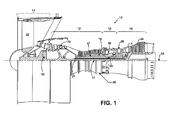
FIG. 1 is a cross-sectional view of a gas turbine engine constructed in accordance with the present disclosure. -
FIG. 2 is a cross-sectional view of an arrangement of concentric rotating shafts, the arrangement including a bearing stack held in place by a stack retainer, in accordance with the present disclosure. -
FIG. 3 is a schematic diagram of a bearing of the bearing stack ofFIG. 2 showing pre-load forces applied to the bearing, in accordance with the present disclosure. -
FIG. 4 is a perspective view of the stack retainer ofFIG. 2 , in accordance with the present disclosure. - It should be understood that the drawings are not necessarily to scale and that the disclosed embodiments are sometimes illustrated diagrammatically and in partial views. In certain instances, details which are not necessary for an understanding of this disclosure or which render other details difficult to perceive may have been omitted. It should be understood, of course, that this disclosure is not limited to the particular embodiments illustrated herein.
- Referring to the drawings, and with specific reference to
FIG. 1 , a gas turbine engine constructed in accordance with the present disclosure is generally referred to by reference numeral 10. Such a gas turbine engine 10 can be used for any number of different applications including, but not limited to, generation of aircraft thrust and land-based power. Moreover, it is to be understood that the sectional view provided inFIG.1 is included simply to provide a basic understanding of the various sections in a gas turbine engine, and not to limit the invention thereto. The present disclosure extends to all types of gas turbine engines used in all types of applications. - The gas turbine engine 10 may have a fan section 11, the fan section 11 drawing in ambient air and directing the ambient air to a
compressor section 12. The incoming air is greatly compressed by thecompressor section 12 and directed to acombustor section 13 where it is mixed with fuel and combusted. The products of that combustion, in the form of very hot and expanding gases, are directed to aturbine section 14 shown to be downstream of thecombustor section 13. Theturbine section 14 and/orcompressor section 12 may each be comprised of a plurality of blades radially extending from a shaft forming rotating sections or rotors. A plurality of vanes may radially extend inwardly from a static section or stator, and are intermeshed with the plurality of blades. In so doing, it can be seen that theturbine section 14,compressor section 12, and fan section 11 all revolve around acentral engine axis 16. - Further, the gas turbine engine 10 may include a
low spool 17 and a high spool 18 mounted for rotation about thecentral engine axis 16 relative to anengine case structure 20. Thelow spool 17 may include aninner shaft 21 that interconnects to afan 22, a low pressure compressor 23 ("LPC") and a low pressure turbine 24 ("LPT"). Theinner shaft 21 may drive thefan 22 directly or through a gearedarchitecture 25 to drive the fan at a lower speed than thelow spool 17. The high spool 18 may include anouter shaft 26 that interconnects a high pressure compressor 27 ("HPC") and high pressure turbine ("HPT") 28. A combustor 30 is arranged between the HPC 27 and the HPT 28. Theinner shaft 21 and the outer shaft may be concentric and rotate about thecentral engine axis 16 which is collinear with their respective longitudinal axes. - Air within the gas turbine engine 10 may be compressed by the LPC 23 and/or the HPC 27. Said air may then be mixed with fuel and burned within the combustor 30 and then may be expanded throughout the HPT 28 and/or the
LPT 24. TheLPT 24 and/or the HPT 28 may rotationally drive thelow spool 17 and the high spool 18, respectively, in response to the expansion of the fuel/air mixture. - The
inner shaft 21 and theouter shaft 26 may be arranged as concentric, independently rotating shafts associated with arotating gear element 31, rotating about thecentral engine axis 16, as shown in greater detail inFIG. 2 . The rotating gear element may be, for example, a gear associated with the gearedarchitecture 25. Alternatively, the rotating gear element may be another rotating element associated with the fan section 11, such as the fan itself. Theinner shaft 21 is operatively coupled to therotating element 31 and may drive the rotatingelement 31 in rotational motion. - Arranged radially outward from the
inner shaft 21, theouter shaft 26 is concentric to theinner shaft 21 and may rotate independently from theinner shaft 21. Aninner bearing stack 32 may be arranged radially outward from theinner shaft 21 yet radially inward with respect to theouter shaft 26. Theinner bearing stack 32 may include one or more ball bearings for providing free, independent radial motion for both theinner shaft 21 andouter shaft 26. For lubrication purposes, theinner bearing stack 32 may distribute oil to associated ball bearings to ensure proper bearing motion and to increase life of theinner bearing stack 32. - Further, the arrangement of
FIG. 2 may include anouter bearing stack 36 located radially outward of theouter shaft 26. Theouter bearing stack 36 may include one or more ball bearings for providing free, independent radial motion of theouter shaft 26. Theouter bearing stack 36 may also assist motion of other elements concentric with the arrangement. Additionally, theouter bearing stack 36 may distribute oil to associated bearings for ensuring proper motion and increasing life of theouter bearing stack 36. - The ball bearings of both the
inner bearing stack 32 and theouter bearing stack 36 may be preloaded to set the bearings in proper axial position and to ensure the bearing stacks 32, 36 are properly held together throughout life of the arrangement. Bearing preload is related to the issue of ball bearing clearance and can be critical for the proper functioning of the bearing. A ball bearing will be fitted with a ball and a housing and will have some level of clearance therebetween, meaning there will be some give between the different parts of the bearing. To remove this internal clearance and create an interference fit, a preload force is applied. Preload is the process wherein a permanent thrust load is applied to the bearing, using force to push the bearing so that it is secure in an associated race and has no axial clearance. - The bearings associated with the
inner bearing stack 32 and theouter bearing stack 36 may be preloaded to eliminate loose motion ("give") in both the radial and axial directions that exists even after the bearing is mounted, radially, on a shaft. When radial clearance exists, vibration and noise of the balls will occur, and the stiffness of the ball bearing will be very low. A force applied in the axial direction is the preload force. The preload force removes unwanted clearances, creates high stiffness, and reduces noise and vibration. Reducing clearances through preload may also help control the rotational accuracy of the bearing, reduce runout, and help prevent the balls in the bearing from skidding on the races. - Turning now to
FIG. 3 , anexample bearing 40 is shown having araceway 41, including anupper race 42 and alower race 43, and aball 45 arranged therein. Optimum preload for thebearing 40 may be individually specified for the specific size of aball 45 and is normally recommended after calculating the optimum operating surface stress at a contact ellipse of thebearing 40. The contact ellipse is the area of contact between theball 45 and theraceway 41 that occurs as a result of elastic deformation of both parts under the load. - More specifically, the contact ellipse area (S) may be defined as an area between the
ball 45 and theraceway 41 and defined as:
where a is the major axis of the contact ellipse area and b is the minor axis of the contact ellipse area. Operating surface stress may be given by Q/S, wherein Q is theball 45 load or load on theraceway 41, said load Q being perpendicular to the area of contact. Operating surface contact stress may generally use the unit "MPa" (Kgf/mm2). - Optimum preload may be calculated based on the optimum surface stress and applied as the force FPL to a member of the
raceway 41. The preload force may be applied to bearings by mechanical means such as a solid preload using a mechanical means of locking the bearing and/or a spring preload which employs a spring to apply the preload force. InFIG. 2 , apreload disc 35 is shown for applying preload force to a race of a bearing of theinner bearing stack 32. Thepreload disc 35 may employ any mechanical means and/or spring means to apply a force to theinner bearing stack 32 for preload. - Guidelines for preload may be based on noise life requirements for specific ball bearings. For example, in general applications with a noise life requirement between 5,000 and 10,000 hours, the optimum preload can be calculated using a contact ellipse stress that does not exceed 1000 MPa. The preload on a bearing may be optimized for various bearings and considering various characteristics of said bearings.
- Preload may also be maintained in an application to bearings using a
bearing stack retainer 50, as seen inFIG. 2 and further detailed inFIG. 4 . A bearingstack retainer 50 may be included to hold the bearing stacks 32, 36 for the concentric inner andouter shafts retainer 50 may mate with the first and second bearing stacks 32, 36 to hold them in position with respect to the inner andouter shafts outer shaft 26. - The bearing stack
retainer 50 may be held in place using one ormore castellations 54 defined by the structure of thebearing stack retainer 50. Thecastellations 54 may match with theouter shaft 26 and use features on the interior and/or exterior of theouter shaft 26 to allow thebearing stack retainer 50 to mate with the inner and outer bearing stacks 32, 36. The retainer will rotate with theouter shaft 36 and thus will always be in contact with the outer and inner rings of the bearings, mating to the inner andouter shafts - In some example designs for the
bearing stack retainer 50, extra material may be used to form anoil dam 52 for the bearing stacks 32, 36. Theoil dam 52 may prevent leakage of excess oil distributed to the bearing stacks 32, 36 and may aid in conserving oil throughout the stack arrangement. - The bearing stack
retainer 50 may allow the ease of rotation for the arrangement by allowing the retainer to rotate with theshafts shafts bearing stack retainer 50 aids in avoiding fretting in the bearings from improper contact. Such abearing stack retainer 50 provides stack containment for preloaded bearings while allowing optimum rotation for all elements of the arrangement. - From the foregoing, it can be seen that the technology disclosed herein has industrial applicability in a variety of settings such as, but not limited to, arrangements for concentric, independently rotating shafts for rotating gear train systems. The rotating gear train systems may be associated with a gas turbine engine. The gas turbine engine may be used in conjunction with an aircraft for generating thrust, or for land-based applications for generating power. The teachings of the present disclosure may provide greater life of components by allowing preload to be maintained for greater life of the arrangement. Creating and maintaining preload on the bearings while using an associatively rotating bearing stack retainer allows proper motion of shafts and maintenance of preload. Because replacing a bearing stack, due to wear, may be costly and labor intensive, this improvement over the prior art may save costs due to the reduction in component replacement and repair costs/time.
- While the present disclosure has been in reference to a gas turbine engine and an aircraft, one skilled in the art will understand that the teachings herein can be used in other applications as well. It is therefore intended that the scope of the invention not be limited by the embodiments presented herein as the best mode for carrying out the invention, but that the invention will include all equivalents falling within the spirit and scope of the claims as well.
Claims (15)
- An arrangement of concentric, independently rotating shafts (21, 26) for a rotating gear train system, the arrangement comprising:an inner shaft (21), the inner shaft (21) operatively coupled to a rotating element;an outer shaft (26), the outer shaft (26) concentric with the inner shaft (21) and arranged radially outward from the inner shaft (21);a first bearing stack (32), the first bearing stack (32) arranged radially outward from the inner shaft (21) and comprising at least one preloaded ball bearing (40);a second bearing stack (36), the second bearing stack (36) arranged radially outward from the outer shaft (26) and comprising at least one ball bearing; anda bearing stack retainer (50), mating with the first and second bearing stacks (32, 36) to hold the first and second bearing stacks (32, 36) in position with respect to the inner and outer shafts (21, 26).
- The arrangement of claim 1, wherein the bearing stack retainer (50) comprises a retaining ring for holding the stack retainer (50) in position with respect to the outer shaft (26).
- The arrangement of claim 1 or 2, wherein the bearing stack retainer (50) defines at least one castellation (54), the castellation (54) designed to hold the stack retainer in position with respect to the outer shaft (26).
- The arrangement of claim 3, wherein the outer shaft (26) defines at least one matching castellation, the at least one matching castellation designed to mate with the at least one castellation (54) of the bearing stack retainer (50).
- The arrangement of any preceding claim, wherein the bearing stack retainer (50) comprises an oil retaining dam (52).
- The arrangement of any preceding claim, further comprising a preload disc (35), the preload disc (35) applying pressure to a race (42, 43) of the preloaded ball bearing (40) of the first bearing stack (32).
- The arrangement of any preceding claim, wherein the bearing stack retainer (50) applies pressure to a race (42, 43) of the ball bearing (40) of the first bearing stack (32) to provide pre-load for the first bearing stack (32).
- A gas turbine engine (10) comprising:a fan section (11), the fan section (11) including a rotating element;a compressor section (12) downstream of the fan section (11);a combustor section (13) downstream of the compressor section (12);a turbine section (14) downstream of the combustor section (13); andthe arrangement of any preceding claim wherein:the inner shaft (21) is operatively coupled to the rotating element of the fan section (11).
- The gas turbine engine of claim 8, wherein the compressor section (12) comprises a high pressure compressor (27) and a low pressure compressor (23) and the turbine section (14) comprises a low pressure turbine (24) and a high pressure turbine (28).
- The gas turbine engine of claim 9, wherein the inner shaft (21) interconnects to the low pressure compressor (23) and the low pressure turbine (24) and the outer shaft (26) interconnects to the high pressure compressor (27) and the high pressure turbine (28).
- A method for arranging concentric, independently rotating shafts (21, 26) for a rotating gear train system, the method comprising:providing an inner shaft (21);operatively coupling the inner shaft (21) to a rotating element;arranging an outer shaft (26) radially outward from the inner shaft (21), the outer shaft (26) concentric with the inner shaft (21);arranging a first bearing stack (32) radially outward from the inner shaft (21), the first bearing stack (32) comprising at least one preloaded ball bearing (40);arranging a second bearing stack (36) radially outward from the outer shaft (26), the second bearing stack (36) comprising at least one ball bearing; andmating a bearing stack retainer (50) with the first and second bearing stacks (32, 36) to hold the first and second bearing stacks (32, 36) in position with respect to the inner and outer shafts (21, 26), the bearing stack retainer (50) coupled with the outer shaft (26) and rotating with the outer shaft (26).
- The method of claim 11, wherein the bearing stack retainer (50) defines at least one castellation (54), the castellation (54) designed to hold the stack retainer (50) in position with respect to the outer shaft (26) wherein, optionally, the outer shaft (26) defines at least one matching castellation, the at least one matching castellation designed to mate with the at least one castellation (54) of the bearing stack retainer (50).
- The method of claim 11 or 12, the method further comprising providing an oil retaining dam (52) using the bearing stack retainer (50).
- The method of claim 11, 12 or 13, further comprising applying pressure for preload of the first bearing stack (32) using a preload disc (35), the preload disc (35) applying pressure to a race (42, 43) of the preloaded ball bearing (40) of the first bearing stack (32).
- The method of any of claims 11 to 14, further comprising applying pressure for preload of the first bearing stack (32) using the bearing stack retainer (50), the bearing stack retainer (50) applying pressure to a race (42, 43) of the ball bearing (40) of the first bearing stack (32).
Applications Claiming Priority (1)
| Application Number | Priority Date | Filing Date | Title |
|---|---|---|---|
| US201461980999P | 2014-04-17 | 2014-04-17 |
Publications (2)
| Publication Number | Publication Date |
|---|---|
| EP2942538A1 true EP2942538A1 (en) | 2015-11-11 |
| EP2942538B1 EP2942538B1 (en) | 2022-06-01 |
Family
ID=52946432
Family Applications (1)
| Application Number | Title | Priority Date | Filing Date |
|---|---|---|---|
| EP15164013.3A Active EP2942538B1 (en) | 2014-04-17 | 2015-04-17 | Multiple bearing stack retention |
Country Status (2)
| Country | Link |
|---|---|
| US (1) | US9790857B2 (en) |
| EP (1) | EP2942538B1 (en) |
Cited By (1)
| Publication number | Priority date | Publication date | Assignee | Title |
|---|---|---|---|---|
| EP3792514A1 (en) * | 2019-09-12 | 2021-03-17 | Pratt & Whitney Canada Corp. | Bearing preload using external gearbox reaction |
Families Citing this family (1)
| Publication number | Priority date | Publication date | Assignee | Title |
|---|---|---|---|---|
| FR3154449A1 (en) * | 2023-10-20 | 2025-04-25 | Safran Aircraft Engines | method of mounting a rotor between two bearings |
Citations (5)
| Publication number | Priority date | Publication date | Assignee | Title |
|---|---|---|---|---|
| EP0668450A2 (en) * | 1994-02-21 | 1995-08-23 | Ishikawajima-Harima Heavy Industries Co., Ltd. | Oil feeding arrangement for shaft seal and bearings |
| JPH09217740A (en) * | 1996-02-09 | 1997-08-19 | Denso Corp | Bearing device and throttle valve control device having the same |
| US6708482B2 (en) * | 2001-11-29 | 2004-03-23 | General Electric Company | Aircraft engine with inter-turbine engine frame |
| FR2882139A1 (en) * | 2005-02-16 | 2006-08-18 | Skf Ab | DEVICE FOR DETECTING ROTATIONAL PARAMETERS OF TWO ELEMENTS |
| US20090249918A1 (en) * | 2005-12-20 | 2009-10-08 | Harmonic Drive Systems Inc. | Finger Joint Mechanism |
Family Cites Families (10)
| Publication number | Priority date | Publication date | Assignee | Title |
|---|---|---|---|---|
| US4871296A (en) * | 1988-11-07 | 1989-10-03 | Allied-Signal Inc. | Decoupler shaft and air turbine starter having such a decoupler |
| US5042963A (en) * | 1989-03-31 | 1991-08-27 | Allied-Signal Inc. | Dual range air turbine starter |
| US5228845A (en) * | 1992-06-30 | 1993-07-20 | Ford Motor Company | External shaft bearing assembly |
| US6585483B2 (en) * | 2001-11-20 | 2003-07-01 | Honeywell International Inc. | Stationary roller shaft formed of a material having a low inclusion content and high hardness |
| US6732502B2 (en) * | 2002-03-01 | 2004-05-11 | General Electric Company | Counter rotating aircraft gas turbine engine with high overall pressure ratio compressor |
| WO2006059995A1 (en) * | 2004-12-01 | 2006-06-08 | United Technologies Corporation | Gearbox lubrication supply system for a tip turbine engine |
| US7547185B2 (en) * | 2005-08-19 | 2009-06-16 | Honeywell International Inc. | Output shaft air/oil separator to redundantly protect against output shaft o-ring leakage |
| US8511986B2 (en) * | 2007-12-10 | 2013-08-20 | United Technologies Corporation | Bearing mounting system in a low pressure turbine |
| GB0905110D0 (en) * | 2009-03-25 | 2009-05-06 | Rolls Royce Plc | Bearing arrangement |
| FR2944558B1 (en) * | 2009-04-17 | 2014-05-02 | Snecma | DOUBLE BODY GAS TURBINE ENGINE PROVIDED WITH SUPPLEMENTARY BP TURBINE BEARING. |
-
2015
- 2015-01-15 US US14/597,830 patent/US9790857B2/en active Active
- 2015-04-17 EP EP15164013.3A patent/EP2942538B1/en active Active
Patent Citations (5)
| Publication number | Priority date | Publication date | Assignee | Title |
|---|---|---|---|---|
| EP0668450A2 (en) * | 1994-02-21 | 1995-08-23 | Ishikawajima-Harima Heavy Industries Co., Ltd. | Oil feeding arrangement for shaft seal and bearings |
| JPH09217740A (en) * | 1996-02-09 | 1997-08-19 | Denso Corp | Bearing device and throttle valve control device having the same |
| US6708482B2 (en) * | 2001-11-29 | 2004-03-23 | General Electric Company | Aircraft engine with inter-turbine engine frame |
| FR2882139A1 (en) * | 2005-02-16 | 2006-08-18 | Skf Ab | DEVICE FOR DETECTING ROTATIONAL PARAMETERS OF TWO ELEMENTS |
| US20090249918A1 (en) * | 2005-12-20 | 2009-10-08 | Harmonic Drive Systems Inc. | Finger Joint Mechanism |
Cited By (1)
| Publication number | Priority date | Publication date | Assignee | Title |
|---|---|---|---|---|
| EP3792514A1 (en) * | 2019-09-12 | 2021-03-17 | Pratt & Whitney Canada Corp. | Bearing preload using external gearbox reaction |
Also Published As
| Publication number | Publication date |
|---|---|
| EP2942538B1 (en) | 2022-06-01 |
| US9790857B2 (en) | 2017-10-17 |
| US20150300256A1 (en) | 2015-10-22 |
Similar Documents
| Publication | Publication Date | Title |
|---|---|---|
| CN104011336B (en) | For the bearing supporting device of gas turbine engine | |
| CN104011335B (en) | For the series connection bearing supporting device of gas-turbine unit | |
| US11352980B2 (en) | Turbine engine with a contra-rotating turbine for an aircraft | |
| EP2224103B1 (en) | Bearing support apparatus with squeeze film damper | |
| CN105745400B (en) | The front cover shell sealed during the Modularized dismounting of the turbojet with reduction gearing | |
| US10174634B2 (en) | Device and method for lubricating a turbomachine rolling bearing | |
| CN114555927B (en) | Turbomachine fan assembly including roller bearing and tilt-contact double row ball bearing | |
| EP2888451B1 (en) | Spring carrier and removable seal carrier | |
| CN111542681B (en) | Shaft assembly for aircraft turbomachine | |
| US20150308510A1 (en) | Systems and methods for engine bearings | |
| US10358941B2 (en) | Gas turbine engine | |
| EP2942538B1 (en) | Multiple bearing stack retention | |
| US10670077B2 (en) | Sealed bearing assembly and method of forming same | |
| US10138940B2 (en) | Roller bearing cage for use in a gearbox | |
| EP3748180B1 (en) | Cylindrical roller bearing containing a crowned inner and outer ring shoulder | |
| CN108952969B (en) | Bearing Housings for Roller Bearing Assemblies | |
| EP3060781B1 (en) | Dismounting the outer race of a rolling bearing | |
| US10054163B2 (en) | Bearing cages for roller bearing assemblies | |
| Sato et al. | Design, Analysis, and Tests of Differential Planetary Gear System for Open Rotor Power Gearbox |
Legal Events
| Date | Code | Title | Description |
|---|---|---|---|
| PUAI | Public reference made under article 153(3) epc to a published international application that has entered the european phase |
Free format text: ORIGINAL CODE: 0009012 |
|
| AK | Designated contracting states |
Kind code of ref document: A1 Designated state(s): AL AT BE BG CH CY CZ DE DK EE ES FI FR GB GR HR HU IE IS IT LI LT LU LV MC MK MT NL NO PL PT RO RS SE SI SK SM TR |
|
| AX | Request for extension of the european patent |
Extension state: BA ME |
|
| 17P | Request for examination filed |
Effective date: 20160511 |
|
| RBV | Designated contracting states (corrected) |
Designated state(s): AL AT BE BG CH CY CZ DE DK EE ES FI FR GB GR HR HU IE IS IT LI LT LU LV MC MK MT NL NO PL PT RO RS SE SI SK SM TR |
|
| RAP1 | Party data changed (applicant data changed or rights of an application transferred) |
Owner name: UNITED TECHNOLOGIES CORPORATION |
|
| STAA | Information on the status of an ep patent application or granted ep patent |
Free format text: STATUS: EXAMINATION IS IN PROGRESS |
|
| 17Q | First examination report despatched |
Effective date: 20190130 |
|
| RAP1 | Party data changed (applicant data changed or rights of an application transferred) |
Owner name: RAYTHEON TECHNOLOGIES CORPORATION |
|
| GRAP | Despatch of communication of intention to grant a patent |
Free format text: ORIGINAL CODE: EPIDOSNIGR1 |
|
| STAA | Information on the status of an ep patent application or granted ep patent |
Free format text: STATUS: GRANT OF PATENT IS INTENDED |
|
| INTG | Intention to grant announced |
Effective date: 20220113 |
|
| GRAS | Grant fee paid |
Free format text: ORIGINAL CODE: EPIDOSNIGR3 |
|
| GRAA | (expected) grant |
Free format text: ORIGINAL CODE: 0009210 |
|
| STAA | Information on the status of an ep patent application or granted ep patent |
Free format text: STATUS: THE PATENT HAS BEEN GRANTED |
|
| AK | Designated contracting states |
Kind code of ref document: B1 Designated state(s): AL AT BE BG CH CY CZ DE DK EE ES FI FR GB GR HR HU IE IS IT LI LT LU LV MC MK MT NL NO PL PT RO RS SE SI SK SM TR |
|
| REG | Reference to a national code |
Ref country code: GB Ref legal event code: FG4D |
|
| REG | Reference to a national code |
Ref country code: AT Ref legal event code: REF Ref document number: 1495546 Country of ref document: AT Kind code of ref document: T Effective date: 20220615 Ref country code: CH Ref legal event code: EP Ref country code: DE Ref legal event code: R096 Ref document number: 602015079223 Country of ref document: DE |
|
| REG | Reference to a national code |
Ref country code: IE Ref legal event code: FG4D |
|
| REG | Reference to a national code |
Ref country code: LT Ref legal event code: MG9D |
|
| REG | Reference to a national code |
Ref country code: NL Ref legal event code: MP Effective date: 20220601 |
|
| PG25 | Lapsed in a contracting state [announced via postgrant information from national office to epo] |
Ref country code: SE Free format text: LAPSE BECAUSE OF FAILURE TO SUBMIT A TRANSLATION OF THE DESCRIPTION OR TO PAY THE FEE WITHIN THE PRESCRIBED TIME-LIMIT Effective date: 20220601 Ref country code: NO Free format text: LAPSE BECAUSE OF FAILURE TO SUBMIT A TRANSLATION OF THE DESCRIPTION OR TO PAY THE FEE WITHIN THE PRESCRIBED TIME-LIMIT Effective date: 20220901 Ref country code: LT Free format text: LAPSE BECAUSE OF FAILURE TO SUBMIT A TRANSLATION OF THE DESCRIPTION OR TO PAY THE FEE WITHIN THE PRESCRIBED TIME-LIMIT Effective date: 20220601 Ref country code: HR Free format text: LAPSE BECAUSE OF FAILURE TO SUBMIT A TRANSLATION OF THE DESCRIPTION OR TO PAY THE FEE WITHIN THE PRESCRIBED TIME-LIMIT Effective date: 20220601 Ref country code: GR Free format text: LAPSE BECAUSE OF FAILURE TO SUBMIT A TRANSLATION OF THE DESCRIPTION OR TO PAY THE FEE WITHIN THE PRESCRIBED TIME-LIMIT Effective date: 20220902 Ref country code: FI Free format text: LAPSE BECAUSE OF FAILURE TO SUBMIT A TRANSLATION OF THE DESCRIPTION OR TO PAY THE FEE WITHIN THE PRESCRIBED TIME-LIMIT Effective date: 20220601 Ref country code: ES Free format text: LAPSE BECAUSE OF FAILURE TO SUBMIT A TRANSLATION OF THE DESCRIPTION OR TO PAY THE FEE WITHIN THE PRESCRIBED TIME-LIMIT Effective date: 20220601 Ref country code: BG Free format text: LAPSE BECAUSE OF FAILURE TO SUBMIT A TRANSLATION OF THE DESCRIPTION OR TO PAY THE FEE WITHIN THE PRESCRIBED TIME-LIMIT Effective date: 20220901 |
|
| REG | Reference to a national code |
Ref country code: AT Ref legal event code: MK05 Ref document number: 1495546 Country of ref document: AT Kind code of ref document: T Effective date: 20220601 |
|
| PG25 | Lapsed in a contracting state [announced via postgrant information from national office to epo] |
Ref country code: RS Free format text: LAPSE BECAUSE OF FAILURE TO SUBMIT A TRANSLATION OF THE DESCRIPTION OR TO PAY THE FEE WITHIN THE PRESCRIBED TIME-LIMIT Effective date: 20220601 Ref country code: PL Free format text: LAPSE BECAUSE OF FAILURE TO SUBMIT A TRANSLATION OF THE DESCRIPTION OR TO PAY THE FEE WITHIN THE PRESCRIBED TIME-LIMIT Effective date: 20220601 Ref country code: LV Free format text: LAPSE BECAUSE OF FAILURE TO SUBMIT A TRANSLATION OF THE DESCRIPTION OR TO PAY THE FEE WITHIN THE PRESCRIBED TIME-LIMIT Effective date: 20220601 |
|
| PG25 | Lapsed in a contracting state [announced via postgrant information from national office to epo] |
Ref country code: NL Free format text: LAPSE BECAUSE OF FAILURE TO SUBMIT A TRANSLATION OF THE DESCRIPTION OR TO PAY THE FEE WITHIN THE PRESCRIBED TIME-LIMIT Effective date: 20220601 |
|
| PG25 | Lapsed in a contracting state [announced via postgrant information from national office to epo] |
Ref country code: SM Free format text: LAPSE BECAUSE OF FAILURE TO SUBMIT A TRANSLATION OF THE DESCRIPTION OR TO PAY THE FEE WITHIN THE PRESCRIBED TIME-LIMIT Effective date: 20220601 Ref country code: SK Free format text: LAPSE BECAUSE OF FAILURE TO SUBMIT A TRANSLATION OF THE DESCRIPTION OR TO PAY THE FEE WITHIN THE PRESCRIBED TIME-LIMIT Effective date: 20220601 Ref country code: RO Free format text: LAPSE BECAUSE OF FAILURE TO SUBMIT A TRANSLATION OF THE DESCRIPTION OR TO PAY THE FEE WITHIN THE PRESCRIBED TIME-LIMIT Effective date: 20220601 Ref country code: PT Free format text: LAPSE BECAUSE OF FAILURE TO SUBMIT A TRANSLATION OF THE DESCRIPTION OR TO PAY THE FEE WITHIN THE PRESCRIBED TIME-LIMIT Effective date: 20221003 Ref country code: EE Free format text: LAPSE BECAUSE OF FAILURE TO SUBMIT A TRANSLATION OF THE DESCRIPTION OR TO PAY THE FEE WITHIN THE PRESCRIBED TIME-LIMIT Effective date: 20220601 Ref country code: CZ Free format text: LAPSE BECAUSE OF FAILURE TO SUBMIT A TRANSLATION OF THE DESCRIPTION OR TO PAY THE FEE WITHIN THE PRESCRIBED TIME-LIMIT Effective date: 20220601 Ref country code: AT Free format text: LAPSE BECAUSE OF FAILURE TO SUBMIT A TRANSLATION OF THE DESCRIPTION OR TO PAY THE FEE WITHIN THE PRESCRIBED TIME-LIMIT Effective date: 20220601 |
|
| PG25 | Lapsed in a contracting state [announced via postgrant information from national office to epo] |
Ref country code: IS Free format text: LAPSE BECAUSE OF FAILURE TO SUBMIT A TRANSLATION OF THE DESCRIPTION OR TO PAY THE FEE WITHIN THE PRESCRIBED TIME-LIMIT Effective date: 20221001 |
|
| REG | Reference to a national code |
Ref country code: DE Ref legal event code: R097 Ref document number: 602015079223 Country of ref document: DE |
|
| REG | Reference to a national code |
Ref country code: FR Ref legal event code: PLFP Year of fee payment: 9 |
|
| PG25 | Lapsed in a contracting state [announced via postgrant information from national office to epo] |
Ref country code: AL Free format text: LAPSE BECAUSE OF FAILURE TO SUBMIT A TRANSLATION OF THE DESCRIPTION OR TO PAY THE FEE WITHIN THE PRESCRIBED TIME-LIMIT Effective date: 20220601 |
|
| PLBE | No opposition filed within time limit |
Free format text: ORIGINAL CODE: 0009261 |
|
| STAA | Information on the status of an ep patent application or granted ep patent |
Free format text: STATUS: NO OPPOSITION FILED WITHIN TIME LIMIT |
|
| PG25 | Lapsed in a contracting state [announced via postgrant information from national office to epo] |
Ref country code: DK Free format text: LAPSE BECAUSE OF FAILURE TO SUBMIT A TRANSLATION OF THE DESCRIPTION OR TO PAY THE FEE WITHIN THE PRESCRIBED TIME-LIMIT Effective date: 20220601 |
|
| 26N | No opposition filed |
Effective date: 20230302 |
|
| PG25 | Lapsed in a contracting state [announced via postgrant information from national office to epo] |
Ref country code: SI Free format text: LAPSE BECAUSE OF FAILURE TO SUBMIT A TRANSLATION OF THE DESCRIPTION OR TO PAY THE FEE WITHIN THE PRESCRIBED TIME-LIMIT Effective date: 20220601 |
|
| P01 | Opt-out of the competence of the unified patent court (upc) registered |
Effective date: 20230520 |
|
| REG | Reference to a national code |
Ref country code: CH Ref legal event code: PL |
|
| PG25 | Lapsed in a contracting state [announced via postgrant information from national office to epo] |
Ref country code: LU Free format text: LAPSE BECAUSE OF NON-PAYMENT OF DUE FEES Effective date: 20230417 |
|
| REG | Reference to a national code |
Ref country code: BE Ref legal event code: MM Effective date: 20230430 |
|
| PG25 | Lapsed in a contracting state [announced via postgrant information from national office to epo] |
Ref country code: MC Free format text: LAPSE BECAUSE OF FAILURE TO SUBMIT A TRANSLATION OF THE DESCRIPTION OR TO PAY THE FEE WITHIN THE PRESCRIBED TIME-LIMIT Effective date: 20220601 |
|
| PG25 | Lapsed in a contracting state [announced via postgrant information from national office to epo] |
Ref country code: MC Free format text: LAPSE BECAUSE OF FAILURE TO SUBMIT A TRANSLATION OF THE DESCRIPTION OR TO PAY THE FEE WITHIN THE PRESCRIBED TIME-LIMIT Effective date: 20220601 Ref country code: LI Free format text: LAPSE BECAUSE OF NON-PAYMENT OF DUE FEES Effective date: 20230430 Ref country code: IT Free format text: LAPSE BECAUSE OF FAILURE TO SUBMIT A TRANSLATION OF THE DESCRIPTION OR TO PAY THE FEE WITHIN THE PRESCRIBED TIME-LIMIT Effective date: 20220601 Ref country code: CH Free format text: LAPSE BECAUSE OF NON-PAYMENT OF DUE FEES Effective date: 20230430 |
|
| REG | Reference to a national code |
Ref country code: IE Ref legal event code: MM4A |
|
| PG25 | Lapsed in a contracting state [announced via postgrant information from national office to epo] |
Ref country code: BE Free format text: LAPSE BECAUSE OF NON-PAYMENT OF DUE FEES Effective date: 20230430 |
|
| PG25 | Lapsed in a contracting state [announced via postgrant information from national office to epo] |
Ref country code: IE Free format text: LAPSE BECAUSE OF NON-PAYMENT OF DUE FEES Effective date: 20230417 |
|
| PG25 | Lapsed in a contracting state [announced via postgrant information from national office to epo] |
Ref country code: IE Free format text: LAPSE BECAUSE OF NON-PAYMENT OF DUE FEES Effective date: 20230417 |
|
| PG25 | Lapsed in a contracting state [announced via postgrant information from national office to epo] |
Ref country code: BG Free format text: LAPSE BECAUSE OF FAILURE TO SUBMIT A TRANSLATION OF THE DESCRIPTION OR TO PAY THE FEE WITHIN THE PRESCRIBED TIME-LIMIT Effective date: 20220601 |
|
| PG25 | Lapsed in a contracting state [announced via postgrant information from national office to epo] |
Ref country code: BG Free format text: LAPSE BECAUSE OF FAILURE TO SUBMIT A TRANSLATION OF THE DESCRIPTION OR TO PAY THE FEE WITHIN THE PRESCRIBED TIME-LIMIT Effective date: 20220601 |
|
| PGFP | Annual fee paid to national office [announced via postgrant information from national office to epo] |
Ref country code: DE Payment date: 20250319 Year of fee payment: 11 |
|
| PG25 | Lapsed in a contracting state [announced via postgrant information from national office to epo] |
Ref country code: CY Free format text: LAPSE BECAUSE OF FAILURE TO SUBMIT A TRANSLATION OF THE DESCRIPTION OR TO PAY THE FEE WITHIN THE PRESCRIBED TIME-LIMIT; INVALID AB INITIO Effective date: 20150417 |
|
| PG25 | Lapsed in a contracting state [announced via postgrant information from national office to epo] |
Ref country code: HU Free format text: LAPSE BECAUSE OF FAILURE TO SUBMIT A TRANSLATION OF THE DESCRIPTION OR TO PAY THE FEE WITHIN THE PRESCRIBED TIME-LIMIT; INVALID AB INITIO Effective date: 20150417 |
|
| REG | Reference to a national code |
Ref country code: DE Ref legal event code: R081 Ref document number: 602015079223 Country of ref document: DE Owner name: RTX CORPORATION (N.D.GES.D. STAATES DELAWARE),, US Free format text: FORMER OWNER: RAYTHEON TECHNOLOGIES CORPORATION, FARMINGTON, CT, US |
|
| PG25 | Lapsed in a contracting state [announced via postgrant information from national office to epo] |
Ref country code: TR Free format text: LAPSE BECAUSE OF FAILURE TO SUBMIT A TRANSLATION OF THE DESCRIPTION OR TO PAY THE FEE WITHIN THE PRESCRIBED TIME-LIMIT Effective date: 20220601 |
|
| PGFP | Annual fee paid to national office [announced via postgrant information from national office to epo] |
Ref country code: GB Payment date: 20260319 Year of fee payment: 12 |
|
| PGFP | Annual fee paid to national office [announced via postgrant information from national office to epo] |
Ref country code: FR Payment date: 20260320 Year of fee payment: 12 |