EP2942527A1 - Axial flow blood pump - Google Patents
Axial flow blood pump Download PDFInfo
- Publication number
- EP2942527A1 EP2942527A1 EP13870230.3A EP13870230A EP2942527A1 EP 2942527 A1 EP2942527 A1 EP 2942527A1 EP 13870230 A EP13870230 A EP 13870230A EP 2942527 A1 EP2942527 A1 EP 2942527A1
- Authority
- EP
- European Patent Office
- Prior art keywords
- casing
- stator
- impeller
- axial
- blood pump
- Prior art date
- Legal status (The legal status is an assumption and is not a legal conclusion. Google has not performed a legal analysis and makes no representation as to the accuracy of the status listed.)
- Granted
Links
- 239000008280 blood Substances 0.000 title claims abstract description 75
- 210000004369 blood Anatomy 0.000 title claims abstract description 74
- 230000002093 peripheral effect Effects 0.000 claims abstract description 26
- 230000017531 blood circulation Effects 0.000 claims description 14
- 239000012530 fluid Substances 0.000 claims description 6
- 239000004696 Poly ether ether ketone Substances 0.000 claims description 5
- 229920002530 polyetherether ketone Polymers 0.000 claims description 5
- 239000011347 resin Substances 0.000 claims description 4
- 229920005989 resin Polymers 0.000 claims description 4
- BZHJMEDXRYGGRV-UHFFFAOYSA-N Vinyl chloride Chemical compound ClC=C BZHJMEDXRYGGRV-UHFFFAOYSA-N 0.000 claims description 3
- 239000004925 Acrylic resin Substances 0.000 claims description 2
- 229920000178 Acrylic resin Polymers 0.000 claims description 2
- 238000005339 levitation Methods 0.000 description 7
- 239000007788 liquid Substances 0.000 description 7
- 230000004087 circulation Effects 0.000 description 4
- 230000000052 comparative effect Effects 0.000 description 4
- 230000008878 coupling Effects 0.000 description 4
- 238000010168 coupling process Methods 0.000 description 4
- 238000005859 coupling reaction Methods 0.000 description 4
- 239000011888 foil Substances 0.000 description 4
- 229920000642 polymer Polymers 0.000 description 4
- 238000010586 diagram Methods 0.000 description 3
- 230000000694 effects Effects 0.000 description 3
- 230000007774 longterm Effects 0.000 description 3
- 238000005516 engineering process Methods 0.000 description 2
- 230000002949 hemolytic effect Effects 0.000 description 2
- 239000004417 polycarbonate Substances 0.000 description 2
- 229920000515 polycarbonate Polymers 0.000 description 2
- 238000011144 upstream manufacturing Methods 0.000 description 2
- RTAQQCXQSZGOHL-UHFFFAOYSA-N Titanium Chemical compound [Ti] RTAQQCXQSZGOHL-UHFFFAOYSA-N 0.000 description 1
- 230000000747 cardiac effect Effects 0.000 description 1
- 230000015556 catabolic process Effects 0.000 description 1
- 230000035602 clotting Effects 0.000 description 1
- 238000010276 construction Methods 0.000 description 1
- 230000005611 electricity Effects 0.000 description 1
- 239000007943 implant Substances 0.000 description 1
- 238000002513 implantation Methods 0.000 description 1
- 238000009434 installation Methods 0.000 description 1
- 239000000463 material Substances 0.000 description 1
- 229910052751 metal Inorganic materials 0.000 description 1
- 239000002184 metal Substances 0.000 description 1
- 150000002739 metals Chemical class 0.000 description 1
- 239000002861 polymer material Substances 0.000 description 1
- 238000005086 pumping Methods 0.000 description 1
- 230000000630 rising effect Effects 0.000 description 1
- 238000007789 sealing Methods 0.000 description 1
- 229920002379 silicone rubber Polymers 0.000 description 1
- 239000004945 silicone rubber Substances 0.000 description 1
- 229910001220 stainless steel Inorganic materials 0.000 description 1
- 239000010935 stainless steel Substances 0.000 description 1
- 239000008399 tap water Substances 0.000 description 1
- 235000020679 tap water Nutrition 0.000 description 1
- 239000010936 titanium Substances 0.000 description 1
- 229910052719 titanium Inorganic materials 0.000 description 1
- 230000009466 transformation Effects 0.000 description 1
- XLYOFNOQVPJJNP-UHFFFAOYSA-N water Substances O XLYOFNOQVPJJNP-UHFFFAOYSA-N 0.000 description 1
- 229910000859 α-Fe Inorganic materials 0.000 description 1
Images



Classifications
-
- F—MECHANICAL ENGINEERING; LIGHTING; HEATING; WEAPONS; BLASTING
- F04—POSITIVE - DISPLACEMENT MACHINES FOR LIQUIDS; PUMPS FOR LIQUIDS OR ELASTIC FLUIDS
- F04D—NON-POSITIVE-DISPLACEMENT PUMPS
- F04D29/00—Details, component parts, or accessories
- F04D29/40—Casings; Connections of working fluid
- F04D29/52—Casings; Connections of working fluid for axial pumps
- F04D29/528—Casings; Connections of working fluid for axial pumps especially adapted for liquid pumps
-
- F—MECHANICAL ENGINEERING; LIGHTING; HEATING; WEAPONS; BLASTING
- F04—POSITIVE - DISPLACEMENT MACHINES FOR LIQUIDS; PUMPS FOR LIQUIDS OR ELASTIC FLUIDS
- F04D—NON-POSITIVE-DISPLACEMENT PUMPS
- F04D3/00—Axial-flow pumps
-
- A—HUMAN NECESSITIES
- A61—MEDICAL OR VETERINARY SCIENCE; HYGIENE
- A61M—DEVICES FOR INTRODUCING MEDIA INTO, OR ONTO, THE BODY; DEVICES FOR TRANSDUCING BODY MEDIA OR FOR TAKING MEDIA FROM THE BODY; DEVICES FOR PRODUCING OR ENDING SLEEP OR STUPOR
- A61M60/00—Blood pumps; Devices for mechanical circulatory actuation; Balloon pumps for circulatory assistance
- A61M60/10—Location thereof with respect to the patient's body
- A61M60/104—Extracorporeal pumps, i.e. the blood being pumped outside the patient's body
- A61M60/109—Extracorporeal pumps, i.e. the blood being pumped outside the patient's body incorporated within extracorporeal blood circuits or systems
-
- A—HUMAN NECESSITIES
- A61—MEDICAL OR VETERINARY SCIENCE; HYGIENE
- A61M—DEVICES FOR INTRODUCING MEDIA INTO, OR ONTO, THE BODY; DEVICES FOR TRANSDUCING BODY MEDIA OR FOR TAKING MEDIA FROM THE BODY; DEVICES FOR PRODUCING OR ENDING SLEEP OR STUPOR
- A61M60/00—Blood pumps; Devices for mechanical circulatory actuation; Balloon pumps for circulatory assistance
- A61M60/20—Type thereof
- A61M60/205—Non-positive displacement blood pumps
- A61M60/216—Non-positive displacement blood pumps including a rotating member acting on the blood, e.g. impeller
- A61M60/226—Non-positive displacement blood pumps including a rotating member acting on the blood, e.g. impeller the blood flow through the rotating member having mainly radial components
- A61M60/232—Centrifugal pumps
-
- A—HUMAN NECESSITIES
- A61—MEDICAL OR VETERINARY SCIENCE; HYGIENE
- A61M—DEVICES FOR INTRODUCING MEDIA INTO, OR ONTO, THE BODY; DEVICES FOR TRANSDUCING BODY MEDIA OR FOR TAKING MEDIA FROM THE BODY; DEVICES FOR PRODUCING OR ENDING SLEEP OR STUPOR
- A61M60/00—Blood pumps; Devices for mechanical circulatory actuation; Balloon pumps for circulatory assistance
- A61M60/20—Type thereof
- A61M60/205—Non-positive displacement blood pumps
- A61M60/216—Non-positive displacement blood pumps including a rotating member acting on the blood, e.g. impeller
- A61M60/237—Non-positive displacement blood pumps including a rotating member acting on the blood, e.g. impeller the blood flow through the rotating member having mainly axial components, e.g. axial flow pumps
-
- A—HUMAN NECESSITIES
- A61—MEDICAL OR VETERINARY SCIENCE; HYGIENE
- A61M—DEVICES FOR INTRODUCING MEDIA INTO, OR ONTO, THE BODY; DEVICES FOR TRANSDUCING BODY MEDIA OR FOR TAKING MEDIA FROM THE BODY; DEVICES FOR PRODUCING OR ENDING SLEEP OR STUPOR
- A61M60/00—Blood pumps; Devices for mechanical circulatory actuation; Balloon pumps for circulatory assistance
- A61M60/40—Details relating to driving
- A61M60/403—Details relating to driving for non-positive displacement blood pumps
- A61M60/422—Details relating to driving for non-positive displacement blood pumps the force acting on the blood contacting member being electromagnetic, e.g. using canned motor pumps
-
- A—HUMAN NECESSITIES
- A61—MEDICAL OR VETERINARY SCIENCE; HYGIENE
- A61M—DEVICES FOR INTRODUCING MEDIA INTO, OR ONTO, THE BODY; DEVICES FOR TRANSDUCING BODY MEDIA OR FOR TAKING MEDIA FROM THE BODY; DEVICES FOR PRODUCING OR ENDING SLEEP OR STUPOR
- A61M60/00—Blood pumps; Devices for mechanical circulatory actuation; Balloon pumps for circulatory assistance
- A61M60/80—Constructional details other than related to driving
- A61M60/802—Constructional details other than related to driving of non-positive displacement blood pumps
- A61M60/818—Bearings
- A61M60/82—Magnetic bearings
-
- F—MECHANICAL ENGINEERING; LIGHTING; HEATING; WEAPONS; BLASTING
- F04—POSITIVE - DISPLACEMENT MACHINES FOR LIQUIDS; PUMPS FOR LIQUIDS OR ELASTIC FLUIDS
- F04D—NON-POSITIVE-DISPLACEMENT PUMPS
- F04D13/00—Pumping installations or systems
- F04D13/02—Units comprising pumps and their driving means
- F04D13/06—Units comprising pumps and their driving means the pump being electrically driven
- F04D13/0646—Units comprising pumps and their driving means the pump being electrically driven the hollow pump or motor shaft being the conduit for the working fluid
-
- F—MECHANICAL ENGINEERING; LIGHTING; HEATING; WEAPONS; BLASTING
- F04—POSITIVE - DISPLACEMENT MACHINES FOR LIQUIDS; PUMPS FOR LIQUIDS OR ELASTIC FLUIDS
- F04D—NON-POSITIVE-DISPLACEMENT PUMPS
- F04D29/00—Details, component parts, or accessories
- F04D29/18—Rotors
- F04D29/181—Axial flow rotors
-
- F—MECHANICAL ENGINEERING; LIGHTING; HEATING; WEAPONS; BLASTING
- F04—POSITIVE - DISPLACEMENT MACHINES FOR LIQUIDS; PUMPS FOR LIQUIDS OR ELASTIC FLUIDS
- F04D—NON-POSITIVE-DISPLACEMENT PUMPS
- F04D29/00—Details, component parts, or accessories
- F04D29/60—Mounting; Assembling; Disassembling
- F04D29/64—Mounting; Assembling; Disassembling of axial pumps
- F04D29/648—Mounting; Assembling; Disassembling of axial pumps especially adapted for liquid pumps
-
- A—HUMAN NECESSITIES
- A61—MEDICAL OR VETERINARY SCIENCE; HYGIENE
- A61M—DEVICES FOR INTRODUCING MEDIA INTO, OR ONTO, THE BODY; DEVICES FOR TRANSDUCING BODY MEDIA OR FOR TAKING MEDIA FROM THE BODY; DEVICES FOR PRODUCING OR ENDING SLEEP OR STUPOR
- A61M60/00—Blood pumps; Devices for mechanical circulatory actuation; Balloon pumps for circulatory assistance
- A61M60/10—Location thereof with respect to the patient's body
- A61M60/122—Implantable pumps or pumping devices, i.e. the blood being pumped inside the patient's body
- A61M60/126—Implantable pumps or pumping devices, i.e. the blood being pumped inside the patient's body implantable via, into, inside, in line, branching on, or around a blood vessel
- A61M60/148—Implantable pumps or pumping devices, i.e. the blood being pumped inside the patient's body implantable via, into, inside, in line, branching on, or around a blood vessel in line with a blood vessel using resection or like techniques, e.g. permanent endovascular heart assist devices
-
- A—HUMAN NECESSITIES
- A61—MEDICAL OR VETERINARY SCIENCE; HYGIENE
- A61M—DEVICES FOR INTRODUCING MEDIA INTO, OR ONTO, THE BODY; DEVICES FOR TRANSDUCING BODY MEDIA OR FOR TAKING MEDIA FROM THE BODY; DEVICES FOR PRODUCING OR ENDING SLEEP OR STUPOR
- A61M60/00—Blood pumps; Devices for mechanical circulatory actuation; Balloon pumps for circulatory assistance
- A61M60/80—Constructional details other than related to driving
- A61M60/802—Constructional details other than related to driving of non-positive displacement blood pumps
- A61M60/818—Bearings
- A61M60/824—Hydrodynamic or fluid film bearings
-
- F—MECHANICAL ENGINEERING; LIGHTING; HEATING; WEAPONS; BLASTING
- F04—POSITIVE - DISPLACEMENT MACHINES FOR LIQUIDS; PUMPS FOR LIQUIDS OR ELASTIC FLUIDS
- F04D—NON-POSITIVE-DISPLACEMENT PUMPS
- F04D29/00—Details, component parts, or accessories
- F04D29/40—Casings; Connections of working fluid
- F04D29/52—Casings; Connections of working fluid for axial pumps
- F04D29/54—Fluid-guiding means, e.g. diffusers
- F04D29/548—Specially adapted for liquid pumps
Definitions
- the present invention relates to a technology of a portable axial-flow blood pump that is practicable as a blood pump for extracorporeal circulation and as an implantable blood pump in the future.
- centrifugal pumps and roller pumps have been mainly used as assist pumps for extracorporeal circulation during and after cardiac operation (hereinafter "a blood pump”) and as an advance preparation (bridge-to-decision) prior to an implant of long term artificial heart.
- a blood pump assist pumps for extracorporeal circulation during and after cardiac operation
- bridge-to-decision advance preparation
- centrifugal pumps are accepted as being economical within a certain scope though they take some cost due to usage of disposable pump heads, and they have the merit of high pressure generation even for high flow situation.
- centrifugal pumps have problems when they are operated as portable blood pumps because the centrifugal pumps contain motor drive units that are not disposed and weigh more than 1 Kg (1.6 Kg for example).
- roller pumps have an advantage of being economical because patient consumables are only tubes.
- the proposed magnetic levitation pump with small size dynamic pressure bearings is equipped with an axial-flow impeller and dynamic pressure bearings, and is also equipped with a rotation axis body having permanent magnets at each end and a magnetic coupling means disposed in such a manner that said magnetic coupling means faces each end of the rotation axis body.
- the magnetic coupling means was closely integrated to the pump main body and the magnetic coupling means was not easily dismounted from the pump main body.
- an implantable axial-flow blood pump containing a blood immersed axle bearing is known as one type of axial-flow pump.
- a cup 34 equipped with a stator impeller 30 and a cup 54 equipped with an exit stator impeller 48 are attached to anterior and posterior balls (38, 52) of a pump rotor 20 that is housed in a housing 12.
- the stator impeller 30 and the exit stator impeller 48 fit the inner periphery of the housing 12 to function as a bearing for the pump rotor 20.
- the pump rotor is equipped with a rotor blade 44 that accelerates blood flow and the blood flow velocity is lowered by an exit stator blade 48 and the rotation is stopped to drain the blood toward the exit 18.
- the motor stator 22 is secured in such a manner that the motor stator 22 encircles the periphery of the stator tube 23 that is secured on the inside of the housing 12.
- auxiliary artificial hearts made of Titanium
- Those patients are children with antithrombogenicity at a low blood flow rate and also elderly people whose heart transplant registration is not permitted.
- Children requires blood pumps that are extremely compact and lightweight, with antithrombogenicity at a low blood flow, and for these reasons the pump has to be selected not from transplantable types but from extracorporeal types and consequently axial-flow pumps that can adopt long and thin motor magnets and can be made small are befitted.
- auxiliary artificial hearts must be made of polymer materials, not of metals, and must have a structure that realizes a pump with driving portion reusable, in consideration of the cost.
- the present invention aims to provide an axial-flow blood pump having a stator and a power supply equipment that are removable in an easy manner and parts excluding the stator and the power supply equipment are disposable.
- the axial-flow blood pump based on the first viewpoint of the present invention is configured to be equipped with a first cylindrically shaped casing blood flows therein, a second casing with guide vanes (diffuser) arranged at the inner peripheral surface thereof, an impeller having a rotor that constitutes an axial-flow blade placed rotatably on the inside of the first casing, a cylindrical stator firmly fixed to the tube periphery of the first casing in a removable way for applying turning force to the rotor and a joint for enabling free assembling and disassembling of the first casing and the second casing.
- guide vanes diffuser
- stator and the power supply equipment are easily disassembled and the pump member being in contact with blood, namely parts excluding the stator and the power supply equipment can be made to be disposable.
- the shape of the stator can be freely selected so long as the stator shape concerned can be firmly attached to the peripheral portion of the first cylindrical casing by any one of fitting, engagement or screwing in a detachable manner.
- the cross-sectional shape orthogonally intersecting the longitudinal direction of the inner periphery of the stator can be freely selected among a circle or polygons so long as it is firmly attached to the outer periphery of the first cylindrical casing in a detachable manner.
- the shape of the outer periphery of the stator is not specifically limited.
- the stator has a cylindrical shape for achieving portability, convenience and miniaturization.
- the stator can be firmly attached by fitting to the peripheral surface of the first casing and the stator can be made to be detachable from the first casing. Namely, assembling and disassembling of the axial-flow blood pump can be easily performed by dismantling the stator from the first casing or inserting the stator into the first casing like a ring.
- guide vanes (diffuser) is installed at the inner peripheral surface of the second casing in order to restore the swirling liquid flow caused by the rotation of the impeller to the rectilinear liquid flow.
- the first casing is a tapered shape tube expanding from the inlet
- the second casing is a tapered shape tube expanding from the discharge opening
- the impeller has a tapered shape to be storable on the inside of the first casing
- the inner periphery of the stator has a tapered shape.
- the inner periphery of the stator has a tapered shape so that the stator can be attached more firmly to the outer periphery of the first casing having a tube of a taper shape by either fitting or screwing in a detachable manner mo.
- the stator with its tapered inner periphery can be attached easily and firmly to the outer periphery of the casing and the stator can be made to be detachable from the casing in an easier manner, in comparison to a case in which the inner periphery of a stator is not tapered. Namely, easier assembling and disassembling become available such as the stator to be dismantled from the casing or inserted to the casing more easily.
- the joining portion is firmly fixed to the outer periphery of the second casing by any one of fitting, engagement or screwing, and is composed of a socket member fitable to the stator, and an O ring is provided at the junction of the first casing and the second casing.
- the shape of the socket member at the joining portion can be in any form as long as the joining portion can be firmly fixed by fitting to the outer periphery of the second cylindrical casing, namely the cross sectional shape orthogonally intersecting the longitudinal direction of the inner periphery of the socket member is somewhat like a circle or polygons which provides firm fixation by fitting to the outer periphery of the second cylindrical casing, as was the case of the stator mentioned above.
- the socket member is in a cylindrical form in order to aim for portability, convenience and miniaturization as was the case of the stator mentioned above.
- the socket member can be firmly fixed to the outer periphery of the second casing and furthermore, assembling and disassembling of the axial-flow pump can be easily performed by dismantling the socket member from the second casing or inserting the socket member into the second casing like a ring.
- airtightness at the junction can be improved by installing an O ring at the junction of the first casing and the second casing.
- the axial-flow blood pump based on the second viewpoint according to the present invention consists of the configuration as listed in 1) to 5) below with such a configuration in which the stator and the power supply equipment are detachable and reusable, and the parts excluding the stator and the power supply equipment are disposable.
- the stator and the power supply equipment can be easily detached and the parts except the stator and the power supply equipment can be disposable.
- the power supply equipment involves either a system that draws in the electricity from the external power supply via a wall socket or a battery power source such as dry cells, including a power source cable.
- the power source cable here is connected to the stator and the stator can take in electric power from the external power source or a battery.
- an internal bladed wheel rotates by the magnetic force of the ring-shaped stator.
- Such a rotation power of the impeller generates a pumping power that pushes out blood from the inlet of the casing toward the outlet to form a pump.
- an axial flow type blade is employed as the blade.
- the configurations 1) to 5) above enable assembling and disassembling.
- the stator can be detachable from the first casing like a ring because the stator is circular and can be firmly fixed by fitting to the outer periphery of the first cylindrical casing.
- An axial-flow blood pump with a disposable pump and a reusable motor can be realized due to the configuration in which the stator can be detached from the first casing like a ring.
- the impeller that rotates around the axis is equipped with a hydrodynamic bearing or a pivot bearing.
- the impeller can operate noncontact rotation and the impeller is supported in the state of rising on the inside of the first casing.
- a pivot bearing that supports the impeller in the rotation axis direction is established on the inside of the first casing.
- the form of the pivot bearing is made to be small bar-shaped with a small supporting width, for example, in order to make obstruction of liquid flow as small as possible.
- end face far from the inlet of the first casing and the end face far from the outlet of the second facing are joined together. Accordingly, these end faces are formed to have the same shape, namely the same diameter in the case where the shape is a tube.
- the second casing is hard and cylindrical, and vanes (diffuser) that restores the liquid flow from slewing one to rectilinear one are connected on the inside of the second casing.
- the reason for setting up guide vanes (diffuser) at the inner peripheral surface of the second casing is to restore the slewing liquid flow caused by the rotation of the impeller to a rectilinear liquid flow.
- the first casing is a tapered tube expanding from the inlet
- the second casing is a tapered tube expanding from the outlet
- the impeller is tapered to be storable on the inside of the first casing and the inner periphery of the stator is tapered.
- the inner periphery of the stator is tapered and the stator can be firmly fixed by fitting with detachability to the outer periphery of the first casing which is a tapered tube.
- the stator can be firmly fixed by fitting easily and securely to the outer periphery of the casing, due to its tapered inner periphery, and the stator can be made to be detachable with ease from the casing, in comparison with a cylindrical casing not tapered. Namely, assembling and disassembling of the pump can be more easily performed by detaching the stator from the casing or inserting the stator into the casing.
- the structure that enables the ring-shaped stator to be firmly fixed by fitting to the outer periphery of the first casing includes a tapered lateral surface of the first casing and also a tapered inner periphery of the stator, such a structure is simpler.
- dislodgment of the impeller itself can be prevented by making the structure of the impeller tapered to be storable on the inside of the first casing.
- the junction has a nut structure, a locking section is arranged at the stator and a screw thread is arranged at the outer periphery of the socket member. And a nut is engaged to an engaging member of the stator to be screwed with a screw thread of the socket member.
- the junction includes a nut structure, a locking section is arranged at the socket member and a screw thread is arranged at the outer periphery of the stator. And a nut is engaged to an engaging member of the socket member to be screwed with a screw thread of the stator.
- an arrangement in which the first casing is a tube with a curve starting at the inlet, a pivot bearing is disposed at the inner periphery of the first casing and a stator fixing member for fixing said stator at the outer periphery of the first casing is disposed can be suitably used.
- a pivot bearing can be disposed on the inside of the inner periphery of the first casing by forming the first casing into a tube shape with its curve starting from the inlet.
- the shape of the pivot bearing can be a rod with a small width having the length of the internal diameter of the first casing and a pivot bearing is disposed on the inside of the inner periphery of the first casing to make effects of a hindrance against liquid flow smaller.
- the axial-flow blade is of groove type and the fluid that circulates the outer surface of the impeller generates dynamic pressure between the outer surface of the impeller and the wall surface of the inner periphery of the first casing that accommodates the impeller.
- Dynamic pressure can be efficiently generated between the outer surface of the impeller and the wall surface of the inner periphery of the first casing that accommodates the impeller by the fluid that circulates the outer surface of the impeller based on the use of the axial flow blade of groove type that does not employ airfoil type as the axial flow blade, and the impeller can rotate in a noncontact manner against the first casing.
- the outer surface of the impeller becomes a hydrodynamic bearing of a multi circular arc type.
- the impeller body, the first casing, the second casing and the socket member are composed of resin material selected from polycarbonate, PEEK (polyether ether ketone), acrylic resin or vinyl chloride resin, and are disposed after use.
- the polymers described above are used as members of the pump parts such as the impeller main body, the casing and the socket excluding drive motors, permanent magnets and electric cables, for realizing weight saving of the axial-flow blood pump.
- the axial-flow blood pump based on the second viewpoint according to the present invention as mentioned above preferably contains an O ring at the junction between the first casing and the second casing. It is because preparation of an O ring at the junction between the end face far from the inlet of the first casing and the end face far from the outlet of the second casing provides higher air tightness of the junction.
- the axial-flow blood pump of the present invention effects such as the stator and the power supply equipment can be easily detached and the parts excluding the stator and the power supply are disposable become available. Also, it is effective in making the blood flow pump miniaturized and weight reduced based on the employment of hard polymers as the pump member excluding the stator and the power supply equipment and accordingly making the axial flow blood pump portable.
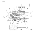
- the structure of the axial-flow blood pump according to the embodiment 1 is explained by referencing Fig. 1 .
- the axial-flow blood pump according to the embodiment 1 consists of the following configurations 1) to 5).
- Symbols 1a and 1b in Fig. 1 represent the direction of the blood flow.
- the end face opposite the inlet 11 of the first casing 5 placed at the upstream region and the end face opposite the outlet 12 of the second casing 3 placed at the downstream region are joined. These end surfaces are made to have the same internal diameter.
- the sealing quality of the junction is elevated by setting up an O ring 7 made of silicone rubber at the junction portion.
- Vanes (diffuser) that restores the rectilinear blood flow from the slewing blood flow is joined on the inside of the second casing 3 in order to restore slewing, by the rotation of the impeller 2, from rotation of the rotational blood flow.
- Both the first casing 5 and the second casing 3 are cylindrical and are tapered in a gentle manner.
- the first casing 5 is a tapered tube extending from the inlet 11 and the second casing 3 is a tapered tube extending from the outlet 12 as shown in Fig. 1 .
- the impeller 2 has a tapered shape storable on the inside of the first casing 5.
- the stator 6 constitutes a ring shape and the inner periphery thereof is tapered. The impeller 2 prevents falling off of the impeller itself by making the shape of the impeller 2 tapered to be storable on the inside of the first casing 5.
- the first casing 5 and the second casing 3 are constituted of rigid polymer.
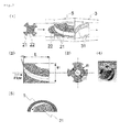
- the impeller 2 on the inside of the first casing 5 is equipped with a grooved axial-flow blade as shown in Fig. 2 (1) .
- an axial-flow pump in general has a structure including a blade
- the axial-flow blood pump according to the present invention includes an grooved axial-flow blade having an axial-flow fluid channel on the inside of the cylindrical first casing 5 due to the necessity to secure a large surface area for the purpose of using a hydrodynamic bearing in a combined usage. As is shown in Fig.
- the impeller 2 is designed aiming to gain angular momentum that is to say enough pressure even under low velocity considering the internal diameter of the first casing 5 at the occasion of designing the impeller 2 (design of geometry parameters of ⁇ 1, ⁇ 2, ⁇ , R).
- an impeller with an exterior as shown in Fig. 2 (4) is used.
- the dynamic bearing of the impeller 2 is a dynamic bearing of multi arcs (4 arcs in the case of Fig. 2 ) (refer to Fig. 2 (1)) and each arc is inclined so that the gap with the interior of the first casing 5 expands in the advancing direction (the direction of the arrow in Fig. 2 (5))
- the inner periphery of the ring shaped stator 6 is tapered and is fixed by fitting to the outer periphery of the first casing 5 that is a tapered tube, in a detachable manner.
- the stator 6 and the first casing 5 can be securely fixed by fitting at the position determined uniquely by the inner diameter of the stator 6 and the outer diameter of the first casing 5 due to the fact that the outer periphery of the first casing 5 and the inner periphery of the stator 6 are both tapered.
- the inner periphery of the socket member 4 is made to be tapered and is fixed by fitting to the outer periphery of the casing 3 with detachability.
- the socket member 4 and the second casing 3 can be securely fixed by fitting at the position determined uniquely by the inner diameter of the socket member 4 and outer diameter of the second casing 3 due to the fact that the outer periphery of the second casing 3 and the inner periphery of the socket member 4 are both tapered.
- the socket member 4 is equipped with a junction that joins with the ring shaped stator 6.
- the junction is nut structured, the socket member is equipped with a locking portion 45 and a screw thread 61 is disposed at the outer periphery of the stator 6.
- a box nut 41 has a screw groove 41 that is engaged with the locking section of the socket member 4 and is screwed together with the screw mountain 61 of the stator 6.
- Fig. 3 shows an exploded schematic diagram of the axial-flow blood pump according to the embodiment 1.
- the stator 6 described in 3) above and the power supply equipment (8, 81, 82) for supplying electric power to the stator 6 are connected by the connector 83 and these are detachable from the main body of the axial-flow pump and recyclable, and parts (the impeller 2, the first casing 5, the socket member 4, the second casing 3, the O ring 7 and the guide vanes (diffuser) 31) excluding the stator 6 and the power supply equipment (8,81,82 and 83) can be disposed after use.
- the impeller 2 and the socket member 4 are also made of rigid polymer such as poly carbonate and PEEK in the same manner as for the first casing 5 and the second casing 3.
- the stator 6 is made of stainless steel or ferrite core.
- a locking section can be disposed at the stator 6 and a screw thread 44 can be disposed at the outer peripheral edge of the socket member 4 for the junction structure of the stator 6 and the socket member 4 described above as shown in Fig. 4 . It is so arranged that the box nut 41 can be engaged with the locking section 62 of the stator 6 and can be screwed with the screw thread 44 of the socket member 4. By such arrangement, the stator 6 and the socket member 4 are joined and the first casing 5 and the second casing 3 are joined.
- a locking section is disposed at the outer peripheral part of the cylindrical second casing 3 and a screw thread 61 is disposed at the outer periphery of the stator 6 to be engaged with the box nut 41 having the groove 43 with the locking section of the outer periphery of the second casing 3 and to be screw-fitted with the screw thread 61 of the stator 6 without using the socket member 4 described in 5) above, to join the first casing 5 and the second casing 3.
- a locking section 6 is disposed at the stator 6 and a screw thread is disposed at the outer periphery of the cylindrical second casing 3 without socket member 4 as described in 5) above. It is acceptable that the first casing 5 and the second casing 3 are joined by the locking of the box nut 41 having the groove 43 with the locking portion of the stator 6 and by the screwing of the box nut 41 having the groove 43 to the screw thread of the outer periphery of the second casing 3.
- groove type impeller of the axial-flow blood pump
- the heat-capacity curve of the groove type impeller is compared with that of the air foil type impeller as a comparative example.
- a closed circuit was formed by the impeller and a soft reservoir was structured by using a vinyl chloride tube of 15mm inner diameter D and using ordinary tap-water, to measure fluid pressures at 2 points in upstream and downstream, respectively and a flow rate of 1 point.
- the heat-capacity curve is shown in Fig. 10 .
- the pressure needs to be multiplied by 1.056 to convert to that of blood because the density value remains at that of water.
- the generated pressure of the comparative example is 6k Pa and that of the embodiment (groove type impeller) is 13k Pa, it is consequently known that two times higher pressure is generated by the groove type impeller than that of the comparison example (air foil type impeller) at the same rotation number.
- a lower rotational number suffices generation of the predetermined pressure and improvement of hemolytic property can be expected.
- the pump portion weighs less than 200 g and the whole weight of the pump system including the power supply equipment 8 weighs only less than 400 g and the axial-flow blood pump here realizes about 1/4 weight of the current centrifugal pump.
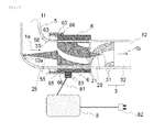
- Fig. 5 shows the structure of the axial-flow blood pump according to the embodiment 2.
- the axial-blood pump according to the embodiment 2 consists of the construction 2-1) to 2-5) as described below.
- the impeller 2 is not dynamic bearing but a pivot bearing.
- the shape of the pivot axis 25 is conical.
- the pivot bearing 10 that supports the impeller 2 in the rotation axis direction is formed on the inside of the first casing5.
- the pivot bearing 10 is rod-shaped with a small width and a length equal to the internal diameter of the first casing 5 in order to make the hindrance to the blood flow on the inside of the first casing 5 as small as possible.
- a locking section may be provided to the stator 6 and a screw thread 44 may be provided at the outer peripheral surface of the socket member 4, as shown in Fig. 4 , for constituting the structure of the junction between the stator 6 and the socket member 4.
- the first casing 5 and the second casing 3 may be joined by joining the stator 6 and the socket member 4 in a manner in which a box nut 41 is engaged with the locking section 62 of the stator 6 and screwed to the screw thread 44 of the socket member 4.
- Fig. 7 shows the structure of the axial-flow blood pump according to the embodiment 3.
- the shape of the pivot axis is spherical while the shape of the pivot axis in the axis-flow blood pump according to the embodiment 2 is conical.
- the shape of the pivot bearing 10 is the same as that in the embodiment 2 however, the shape of the pivot bearing is made to be spherical.
- Fig. 8 shows the structure of the axial-flow blood pump according to the embodiment 4.
- the first casing 5 is tube shaped, the tube being curved starting from the inlet 11, as was described in the axial-flow blood pump according to the embodiment 2, a pivot bearing 10a is disposed at the inner periphery of the first casing 5 and a stator fixing member 55 for fixing the stator 6 is disposed at the outer periphery of the first casing 5.
- the shapes of the first casing 5 and the second casing 3 are not of tapered ones. And the inner periphery of the stator 6 is not tapered also. Because the first casing 5 is tube shaped curved from the inlet 11, the stator 6 is mounted or dismounted from the edge opposite the inlet 11 in the first casing 5.
- a stator fixing member 55 is installed at the outer periphery of the first casing 5, and the screw thread 56 thereof is screwed to the groove 63 of the box nut.
- the box nut 65 is fitted with the protrusion like the locking section 66 of the stator 6.
- a locking section 67 is installed at the stator 6, a locking section 35 having a screw thread is installed at the outer periphery of the cylindrical second casing 3, a box nut 41 is engaged with the locking section 67 of the stator 6 and the screw thread of the locking section 35 installed at the outer periphery of the second casing 3 is screwed to the screw ditch 44, thus the first casing 5 and the second casing 3 are joined.
- first casing 5 and the second casing 3 both in cylindrical form with the same diameter can be integrally molded in advance, not molded by respective member, as shown in Fig. 9 .
- a stator fixation member 55 being installed at the outer periphery of the first casing 5, the screw thread 56 and the screw groove 63 of the box nut 65 being screwed together and further being engaged with the locking section 66 protruding out of the stator 6 by the box nut 65 and consequently the stator 6 being fixed to the outer periphery of the first casing 5.
- the axial-flow blood pump according to the present invention is useful as a circulation assistance pump conducted as a bridge before implantation of a long term artificial heart.
- the axial-flow blood pump 1 according to the present invention is installed in an extracorporeal environment and is used by continuously supplying electric power from the power supply equipment 8 attached to a belt worn around the waist.
- Fig. 11 shows a circumstance in which the axial-flow blood pump 1 according to the present invention is used as an auxiliary of the left heart.
Landscapes
- Engineering & Computer Science (AREA)
- Health & Medical Sciences (AREA)
- Mechanical Engineering (AREA)
- Heart & Thoracic Surgery (AREA)
- General Engineering & Computer Science (AREA)
- Hematology (AREA)
- Anesthesiology (AREA)
- Biomedical Technology (AREA)
- Cardiology (AREA)
- Life Sciences & Earth Sciences (AREA)
- Animal Behavior & Ethology (AREA)
- General Health & Medical Sciences (AREA)
- Public Health (AREA)
- Veterinary Medicine (AREA)
- External Artificial Organs (AREA)
- Structures Of Non-Positive Displacement Pumps (AREA)
Abstract
Description
- The present invention relates to a technology of a portable axial-flow blood pump that is practicable as a blood pump for extracorporeal circulation and as an implantable blood pump in the future.
- Conventionally, centrifugal pumps and roller pumps have been mainly used as assist pumps for extracorporeal circulation during and after cardiac operation (hereinafter "a blood pump") and as an advance preparation (bridge-to-decision) prior to an implant of long term artificial heart. (Refer to the
patent literature 1, for example) There has been little necessity for saving weight of the blood pump itself because blood pumps are ordinarily operated by being placed at the side of a surgical table in an operation room or at the side of the bed in medical wards along with drive means such as drive motors in many cases. - Also, centrifugal pumps are accepted as being economical within a certain scope though they take some cost due to usage of disposable pump heads, and they have the merit of high pressure generation even for high flow situation. However, centrifugal pumps have problems when they are operated as portable blood pumps because the centrifugal pumps contain motor drive units that are not disposed and weigh more than 1 Kg (1.6 Kg for example).
- On the other hand, roller pumps have an advantage of being economical because patient consumables are only tubes. However, it is difficult for roller pumps to be operated continuously for a long term such as more than a week due to fatigue breakdown of tubes.
- Recently, durability of mechanical circulatory support pumps has been improved and the demand for artificial heart becomes intense and consequently usage of blood pump mentioned above has increased and blood pumps of low cost, compact, lightweight and portable are required.
- Also, a configuration to place a stator at the periphery of a centrifugal pump has been conventionally known as a centrifugal pump used for a blood pump. However, there is a problem that such configuration makes a centrifugal pump itself larger in the diametrical direction and consequently the equipment becomes larger.
- Under such circumstances, inventors have already proposed a magnetic levitation pump with small sized dynamic pressure bearings (refer to patent literature 2) in which a stator and a rotor are disposed along the axis direction and the rotor is rotatable under the magnetic levitation status. The proposed magnetic levitation pump with small size dynamic pressure bearings is equipped with an axial-flow impeller and dynamic pressure bearings, and is also equipped with a rotation axis body having permanent magnets at each end and a magnetic coupling means disposed in such a manner that said magnetic coupling means faces each end of the rotation axis body.
- However, in the proposed magnetic levitation pump with dynamic pressure bearings, the magnetic coupling means was closely integrated to the pump main body and the magnetic coupling means was not easily dismounted from the pump main body. Once the proposed magnetic levitation pump is used as an auxiliary pump for internal circulation, it is currently difficult to use the magnetic levitation pump for other operations or other patients from a hygiene perspective and also a perspective of blood clot formation and the situation is that the magnetic levitation pump once used is disposed as it is.
- Also, an implantable axial-flow blood pump containing a blood immersed axle bearing is known as one type of axial-flow pump. (Refer to the patent literature 3) In the configuration of the axial-flow blood pump disclosed in the
patent literature 3, a cup 34 equipped with astator impeller 30 and a cup 54 equipped with an exit stator impeller 48 are attached to anterior and posterior balls (38, 52) of a pump rotor 20 that is housed in ahousing 12. Thestator impeller 30 and the exit stator impeller 48 fit the inner periphery of thehousing 12 to function as a bearing for the pump rotor 20. The pump rotor is equipped with arotor blade 44 that accelerates blood flow and the blood flow velocity is lowered by an exit stator blade 48 and the rotation is stopped to drain the blood toward the exit 18. Note that themotor stator 22 is secured in such a manner that themotor stator 22 encircles the periphery of thestator tube 23 that is secured on the inside of thehousing 12. (Refer tofigures 1 to 4 ; paragraphs 0013 to 0016 of the patent literature 3) - As has been mentioned above, it is observed in the configuration of the axial-flow blood pump disclosed in the
patent literature 3 that the structure of thehousing 12 is complicated and de-installation of themotor stator 22 is accordingly difficult. - Currently, the technology of implantable auxiliary artificial hearts made of Titanium is established almost completely. However, many patients to whom auxiliary artificial hearts cannot be applied exist. Those patients are children with antithrombogenicity at a low blood flow rate and also elderly people whose heart transplant registration is not permitted. Children requires blood pumps that are extremely compact and lightweight, with antithrombogenicity at a low blood flow, and for these reasons the pump has to be selected not from transplantable types but from extracorporeal types and consequently axial-flow pumps that can adopt long and thin motor magnets and can be made small are befitted. Also for elderly people, auxiliary artificial hearts must be made of polymer materials, not of metals, and must have a structure that realizes a pump with driving portion reusable, in consideration of the cost.
-
- [Patent literature 1]
JPA 2004-073400 - [Patent literature 2]
JPA 2003-214374 - [Patent literature 3]
JPA 2008-194482 - In view of the situation mentioned above, the present invention aims to provide an axial-flow blood pump having a stator and a power supply equipment that are removable in an easy manner and parts excluding the stator and the power supply equipment are disposable.
- In order to accomplish the objective mentioned above, the axial-flow blood pump based on the first viewpoint of the present invention is configured to be equipped with a first cylindrically shaped casing blood flows therein, a second casing with guide vanes (diffuser) arranged at the inner peripheral surface thereof, an impeller having a rotor that constitutes an axial-flow blade placed rotatably on the inside of the first casing, a cylindrical stator firmly fixed to the tube periphery of the first casing in a removable way for applying turning force to the rotor and a joint for enabling free assembling and disassembling of the first casing and the second casing.
- Under such configuration, the stator and the power supply equipment are easily disassembled and the pump member being in contact with blood, namely parts excluding the stator and the power supply equipment can be made to be disposable.
- Here, the shape of the stator can be freely selected so long as the stator shape concerned can be firmly attached to the peripheral portion of the first cylindrical casing by any one of fitting, engagement or screwing in a detachable manner. Namely, the cross-sectional shape orthogonally intersecting the longitudinal direction of the inner periphery of the stator can be freely selected among a circle or polygons so long as it is firmly attached to the outer periphery of the first cylindrical casing in a detachable manner. Accordingly, the shape of the outer periphery of the stator is not specifically limited.
- However, it is preferable that the stator has a cylindrical shape for achieving portability, convenience and miniaturization. By making the stator shape cylindrical, the stator can be firmly attached by fitting to the peripheral surface of the first casing and the stator can be made to be detachable from the first casing. Namely, assembling and disassembling of the axial-flow blood pump can be easily performed by dismantling the stator from the first casing or inserting the stator into the first casing like a ring.
- Also, guide vanes (diffuser) is installed at the inner peripheral surface of the second casing in order to restore the swirling liquid flow caused by the rotation of the impeller to the rectilinear liquid flow.
- Here, it is preferable, in the axial-flow blood pump according to the present invention, that the first casing is a tapered shape tube expanding from the inlet, the second casing is a tapered shape tube expanding from the discharge opening, the impeller has a tapered shape to be storable on the inside of the first casing and the inner periphery of the stator has a tapered shape.
- The inner periphery of the stator has a tapered shape so that the stator can be attached more firmly to the outer periphery of the first casing having a tube of a taper shape by either fitting or screwing in a detachable manner mo. The stator with its tapered inner periphery can be attached easily and firmly to the outer periphery of the casing and the stator can be made to be detachable from the casing in an easier manner, in comparison to a case in which the inner periphery of a stator is not tapered. Namely, easier assembling and disassembling become available such as the stator to be dismantled from the casing or inserted to the casing more easily.
- Also, it is preferable that the joining portion is firmly fixed to the outer periphery of the second casing by any one of fitting, engagement or screwing, and is composed of a socket member fitable to the stator, and an O ring is provided at the junction of the first casing and the second casing. For example, the shape of the socket member at the joining portion can be in any form as long as the joining portion can be firmly fixed by fitting to the outer periphery of the second cylindrical casing, namely the cross sectional shape orthogonally intersecting the longitudinal direction of the inner periphery of the socket member is somewhat like a circle or polygons which provides firm fixation by fitting to the outer periphery of the second cylindrical casing, as was the case of the stator mentioned above.
- It is preferable that the socket member is in a cylindrical form in order to aim for portability, convenience and miniaturization as was the case of the stator mentioned above. By making the shape of the socket member cylindrical, the socket member can be firmly fixed to the outer periphery of the second casing and furthermore, assembling and disassembling of the axial-flow pump can be easily performed by dismantling the socket member from the second casing or inserting the socket member into the second casing like a ring.
- Also, airtightness at the junction can be improved by installing an O ring at the junction of the first casing and the second casing.
- Also, the axial-flow blood pump based on the second viewpoint according to the present invention consists of the configuration as listed in 1) to 5) below with such a configuration in which the stator and the power supply equipment are detachable and reusable, and the parts excluding the stator and the power supply equipment are disposable.
- 1) An impeller, being an impeller that rotates around an axis line, being equipped with an axis-flow blade at the side face thereof and having a permanent magnet and a hydrodynamic bearing or a pivot bearing therein.
- 2) A first casing surrounding the periphery of an impeller and being equipped with an inlet.
- 3) A stator in a ring shape, to generate rotating magnetic field for the impeller, and to be firmly fixable to the outer periphery of the first casing.
- 4) A second casing equipped with an exhaust port and guide vanes (diffuser) at the inner periphery thereof.
- 5) A socket member equipped with a junction that can be firmly fitted to the outer periphery of the second casing and can be joined with said stator.
- According to the configuration described above, the stator and the power supply equipment can be easily detached and the parts except the stator and the power supply equipment can be disposable. Here, the power supply equipment involves either a system that draws in the electricity from the external power supply via a wall socket or a battery power source such as dry cells, including a power source cable. The power source cable here is connected to the stator and the stator can take in electric power from the external power source or a battery.
- In the configuration described above, an internal bladed wheel (impeller) rotates by the magnetic force of the ring-shaped stator. Such a rotation power of the impeller generates a pumping power that pushes out blood from the inlet of the casing toward the outlet to form a pump. For miniaturization of the pump, an axial flow type blade is employed as the blade.
- Also, the configurations 1) to 5) above enable assembling and disassembling. The stator can be detachable from the first casing like a ring because the stator is circular and can be firmly fixed by fitting to the outer periphery of the first cylindrical casing. An axial-flow blood pump with a disposable pump and a reusable motor can be realized due to the configuration in which the stator can be detached from the first casing like a ring.
- The impeller that rotates around the axis is equipped with a hydrodynamic bearing or a pivot bearing. In the case of the hydrodynamic bearing, the impeller can operate noncontact rotation and the impeller is supported in the state of rising on the inside of the first casing.
- Also, in the case of the pivot bearing, a pivot bearing that supports the impeller in the rotation axis direction is established on the inside of the first casing. The form of the pivot bearing is made to be small bar-shaped with a small supporting width, for example, in order to make obstruction of liquid flow as small as possible.
- Here, the end face far from the inlet of the first casing and the end face far from the outlet of the second facing are joined together. Accordingly, these end faces are formed to have the same shape, namely the same diameter in the case where the shape is a tube.
- Also, the second casing is hard and cylindrical, and vanes (diffuser) that restores the liquid flow from slewing one to rectilinear one are connected on the inside of the second casing. The reason for setting up guide vanes (diffuser) at the inner peripheral surface of the second casing is to restore the slewing liquid flow caused by the rotation of the impeller to a rectilinear liquid flow.
- Here, it is preferable that the first casing is a tapered tube expanding from the inlet, the second casing is a tapered tube expanding from the outlet, the impeller is tapered to be storable on the inside of the first casing and the inner periphery of the stator is tapered.
- The inner periphery of the stator is tapered and the stator can be firmly fixed by fitting with detachability to the outer periphery of the first casing which is a tapered tube. The stator can be firmly fixed by fitting easily and securely to the outer periphery of the casing, due to its tapered inner periphery, and the stator can be made to be detachable with ease from the casing, in comparison with a cylindrical casing not tapered. Namely, assembling and disassembling of the pump can be more easily performed by detaching the stator from the casing or inserting the stator into the casing.
- If the structure that enables the ring-shaped stator to be firmly fixed by fitting to the outer periphery of the first casing includes a tapered lateral surface of the first casing and also a tapered inner periphery of the stator, such a structure is simpler.
- Furthermore, dislodgment of the impeller itself can be prevented by making the structure of the impeller tapered to be storable on the inside of the first casing.
- Furthermore, in the axial-flow blood pump mentioned above, the junction has a nut structure, a locking section is arranged at the stator and a screw thread is arranged at the outer periphery of the socket member. And a nut is engaged to an engaging member of the stator to be screwed with a screw thread of the socket member. By such arrangement, the first casing and the second casing can be connected easily and firmly by connecting the socket member and the stator.
- And also in the axial-flow blood pump mentioned above, the junction includes a nut structure, a locking section is arranged at the socket member and a screw thread is arranged at the outer periphery of the stator. And a nut is engaged to an engaging member of the socket member to be screwed with a screw thread of the stator. By such arrangement, the first casing and the second casing can be joined easily and firmly by joining the stator and the socket member.
- Furthermore, in the axial-flow blood pump based on the second point of view of the present invention, an arrangement in which the first casing is a tube with a curve starting at the inlet, a pivot bearing is disposed at the inner periphery of the first casing and a stator fixing member for fixing said stator at the outer periphery of the first casing is disposed can be suitably used.
- A pivot bearing can be disposed on the inside of the inner periphery of the first casing by forming the first casing into a tube shape with its curve starting from the inlet. The shape of the pivot bearing can be a rod with a small width having the length of the internal diameter of the first casing and a pivot bearing is disposed on the inside of the inner periphery of the first casing to make effects of a hindrance against liquid flow smaller.
- For the axial-flow blood pump according to the present invention mentioned above, it is preferable that the axial-flow blade is of groove type and the fluid that circulates the outer surface of the impeller generates dynamic pressure between the outer surface of the impeller and the wall surface of the inner periphery of the first casing that accommodates the impeller.
- Dynamic pressure can be efficiently generated between the outer surface of the impeller and the wall surface of the inner periphery of the first casing that accommodates the impeller by the fluid that circulates the outer surface of the impeller based on the use of the axial flow blade of groove type that does not employ airfoil type as the axial flow blade, and the impeller can rotate in a noncontact manner against the first casing.
- The outer surface of the impeller becomes a hydrodynamic bearing of a multi circular arc type.
- Also, in the axial-flow blood pump according to the present invention mentioned above, it is preferable that the impeller body, the first casing, the second casing and the socket member are composed of resin material selected from polycarbonate, PEEK (polyether ether ketone), acrylic resin or vinyl chloride resin, and are disposed after use.
- The polymers described above are used as members of the pump parts such as the impeller main body, the casing and the socket excluding drive motors, permanent magnets and electric cables, for realizing weight saving of the axial-flow blood pump.
- It should be noted that the axial-flow blood pump based on the second viewpoint according to the present invention as mentioned above preferably contains an O ring at the junction between the first casing and the second casing. It is because preparation of an O ring at the junction between the end face far from the inlet of the first casing and the end face far from the outlet of the second casing provides higher air tightness of the junction.
- According to the axial-flow blood pump of the present invention, effects such as the stator and the power supply equipment can be easily detached and the parts excluding the stator and the power supply are disposable become available. Also, it is effective in making the blood flow pump miniaturized and weight reduced based on the employment of hard polymers as the pump member excluding the stator and the power supply equipment and accordingly making the axial flow blood pump portable.
-
- [
Fig. 1 ] An explanatory figure of the axial-flow blood pump structure according to theembodiment 1 - [
Fig. 2 ] An explanatory figure of the impeller of the axial-flow pump according to theembodiment 1 - [
Fig. 3 ] An exploded schematic diagram of the axial-flow blood pump according to theembodiment 1 - [
Fig. 4 ] An explanatory figure of the other nut structure of the axial-flow blood pump according to theembodiment 1 - [
Fig. 5 ] An explanatory figure of the axial-flow blood pump structure according to theembodiment 2 - [
Fig. 6 ] An explanatory figure of the pivot bearing of the axial-flow blood pump according to theembodiment 2 - [
Fig. 7 ] An explanatory figure of the axial-flow blood pump structure according to theembodiment 3 - [
Fig. 8 ] An explanatory figure of the axial-flow blood pump structure according to the embodiment 4 (1) - [
Fig. 9 ] An explanatory figure of the axial-flow blood pump structure according to the embodiment 4 (2) - [
Fig. 10 ] A lifting height curve of the pump - [
Fig. 11 ] A conceptual diagram of the axial-flow blood pump extracorporeally installed - Below, the modes for carrying out the present invention will be explained in detail by referencing figures. Note that the range of the present invention is not limited to the following embodiments and figures but many changes and transformation can be applicable.
- The structure of the axial-flow blood pump according to the
embodiment 1 is explained by referencingFig. 1 . The axial-flow blood pump according to theembodiment 1 consists of the following configurations 1) to 5). - 1) An
impeller 2 that rotates around the axis, being equipped with anaxial blade 21 at the outer peripheral side face thereof and a permanent magnet and a dynamic pressure bearing 22 on the inside thereof - 2) A cylindrical
first casing 5 encircling the side face of theimpeller 2, equipped with aninlet 11 - 3) A ring shaped stator capable of being fixed by fitting to the outer periphery of the first casing and capable of generating rotational magnetic field around the
impeller 2 - 4) A cylindrical
second casing 3 having anoutlet 12 and guide vanes (diffuser) at the inner peripheral surface thereof - 5) A
cylindrical socket member 4 to be adhered by fitting to the outer periphery of the cylindricalsecond casing 3 and also to be equipped with a junction portion capable of being joined to a ring shapedstator 6 -
Symbols Fig. 1 represent the direction of the blood flow. The end face opposite theinlet 11 of thefirst casing 5 placed at the upstream region and the end face opposite theoutlet 12 of thesecond casing 3 placed at the downstream region are joined. These end surfaces are made to have the same internal diameter. The sealing quality of the junction is elevated by setting up anO ring 7 made of silicone rubber at the junction portion. - Vanes (diffuser) that restores the rectilinear blood flow from the slewing blood flow is joined on the inside of the
second casing 3 in order to restore slewing, by the rotation of theimpeller 2, from rotation of the rotational blood flow. - Both the
first casing 5 and thesecond casing 3 are cylindrical and are tapered in a gentle manner. Namely, thefirst casing 5 is a tapered tube extending from theinlet 11 and thesecond casing 3 is a tapered tube extending from theoutlet 12 as shown inFig. 1 . Theimpeller 2 has a tapered shape storable on the inside of thefirst casing 5. Further, thestator 6 constitutes a ring shape and the inner periphery thereof is tapered. Theimpeller 2 prevents falling off of the impeller itself by making the shape of theimpeller 2 tapered to be storable on the inside of thefirst casing 5. - The
first casing 5 and thesecond casing 3 are constituted of rigid polymer. Theimpeller 2 on the inside of thefirst casing 5 is equipped with a grooved axial-flow blade as shown inFig. 2 (1) . Although an axial-flow pump in general has a structure including a blade, the axial-flow blood pump according to the present invention includes an grooved axial-flow blade having an axial-flow fluid channel on the inside of the cylindricalfirst casing 5 due to the necessity to secure a large surface area for the purpose of using a hydrodynamic bearing in a combined usage. As is shown inFig. 2 (2 ) and(3) , theimpeller 2 is designed aiming to gain angular momentum that is to say enough pressure even under low velocity considering the internal diameter of thefirst casing 5 at the occasion of designing the impeller 2 (design of geometry parameters ofφ 1,φ 2, α, R). In theembodiment 1, an impeller with an exterior as shown inFig. 2 (4) is used. The dynamic bearing of theimpeller 2 is a dynamic bearing of multi arcs (4 arcs in the case ofFig. 2 ) (refer toFig. 2 (1)) and each arc is inclined so that the gap with the interior of thefirst casing 5 expands in the advancing direction (the direction of the arrow inFig. 2 (5)) - Also, the inner periphery of the ring shaped
stator 6 is tapered and is fixed by fitting to the outer periphery of thefirst casing 5 that is a tapered tube, in a detachable manner. Thestator 6 and thefirst casing 5 can be securely fixed by fitting at the position determined uniquely by the inner diameter of thestator 6 and the outer diameter of thefirst casing 5 due to the fact that the outer periphery of thefirst casing 5 and the inner periphery of thestator 6 are both tapered. - Also, the inner periphery of the
socket member 4 is made to be tapered and is fixed by fitting to the outer periphery of thecasing 3 with detachability. Thesocket member 4 and thesecond casing 3 can be securely fixed by fitting at the position determined uniquely by the inner diameter of thesocket member 4 and outer diameter of thesecond casing 3 due to the fact that the outer periphery of thesecond casing 3 and the inner periphery of thesocket member 4 are both tapered. - The
socket member 4 is equipped with a junction that joins with the ring shapedstator 6. The junction is nut structured, the socket member is equipped with a lockingportion 45 and ascrew thread 61 is disposed at the outer periphery of thestator 6. And abox nut 41 has ascrew groove 41 that is engaged with the locking section of thesocket member 4 and is screwed together with thescrew mountain 61 of thestator 6. Thus, thestator 6 and thesocket member 4 are securely joined and thefirst casing 5 and thesecond casing 3 are joined. -
Fig. 3 shows an exploded schematic diagram of the axial-flow blood pump according to theembodiment 1. - The
stator 6 described in 3) above and the power supply equipment (8, 81, 82) for supplying electric power to thestator 6 are connected by theconnector 83 and these are detachable from the main body of the axial-flow pump and recyclable, and parts (theimpeller 2, thefirst casing 5, thesocket member 4, thesecond casing 3, theO ring 7 and the guide vanes (diffuser) 31) excluding thestator 6 and the power supply equipment (8,81,82 and 83) can be disposed after use. Theimpeller 2 and thesocket member 4 are also made of rigid polymer such as poly carbonate and PEEK in the same manner as for thefirst casing 5 and thesecond casing 3. And thestator 6 is made of stainless steel or ferrite core. - Note that a locking section can be disposed at the
stator 6 and ascrew thread 44 can be disposed at the outer peripheral edge of thesocket member 4 for the junction structure of thestator 6 and thesocket member 4 described above as shown inFig. 4 . It is so arranged that thebox nut 41 can be engaged with thelocking section 62 of thestator 6 and can be screwed with thescrew thread 44 of thesocket member 4. By such arrangement, thestator 6 and thesocket member 4 are joined and thefirst casing 5 and thesecond casing 3 are joined. - It can be acceptably arranged that a locking section is disposed at the outer peripheral part of the cylindrical
second casing 3 and ascrew thread 61 is disposed at the outer periphery of thestator 6 to be engaged with thebox nut 41 having thegroove 43 with the locking section of the outer periphery of thesecond casing 3 and to be screw-fitted with thescrew thread 61 of thestator 6 without using thesocket member 4 described in 5) above, to join thefirst casing 5 and thesecond casing 3. - Similarly, it can be acceptably arranged that a
locking section 6 is disposed at thestator 6 and a screw thread is disposed at the outer periphery of the cylindricalsecond casing 3 withoutsocket member 4 as described in 5) above. It is acceptable that thefirst casing 5 and thesecond casing 3 are joined by the locking of thebox nut 41 having thegroove 43 with the locking portion of thestator 6 and by the screwing of thebox nut 41 having thegroove 43 to the screw thread of the outer periphery of thesecond casing 3. - Next, the heat-capacity curve of the axial-flow blood pump according to the
embodiment 1 is explained. - With regard to the groove type axial-flow blade impeller (hereinafter "groove type impeller") of the axial-flow blood pump, the heat-capacity curve of the groove type impeller is compared with that of the air foil type impeller as a comparative example.
- In the comparative experiment, a closed circuit was formed by the impeller and a soft reservoir was structured by using a vinyl chloride tube of 15mm inner diameter D and using ordinary tap-water, to measure fluid pressures at 2 points in upstream and downstream, respectively and a flow rate of 1 point.
- The heat-capacity curve is shown in
Fig. 10 . Note that the pressure needs to be multiplied by 1.056 to convert to that of blood because the density value remains at that of water. When a comparison is made under the common condition of the rotation number at12500 rpm and the fluid volume at 5 litters/minute, the generated pressure of the comparative example (air foil type impeller) is 6k Pa and that of the embodiment (groove type impeller) is 13k Pa, it is consequently known that two times higher pressure is generated by the groove type impeller than that of the comparison example (air foil type impeller) at the same rotation number. Conversely, even a lower rotational number suffices generation of the predetermined pressure and improvement of hemolytic property can be expected. It is known that the hemolytic property was improved by 20% when comparison is made between the embodiment (the groove type impeller) where the rotation number was 12500 rpm and the peripheral velocity was 9.8 m/s corresponding to the pressure of 100mm Hg and the comparative example (air foil type impeller) where the rotation number was 15000 rpm and the peripheral velocity was 11.8 m/s. - For the axial-flow blood pump according to the
embodiment 1, the pump portion weighs less than 200 g and the whole weight of the pump system including thepower supply equipment 8 weighs only less than 400 g and the axial-flow blood pump here realizes about 1/4 weight of the current centrifugal pump. -
Fig. 5 shows the structure of the axial-flow blood pump according to theembodiment 2. The axial-blood pump according to theembodiment 2 consists of the construction 2-1) to 2-5) as described below. - 2-1) an impeller that rotates around the axis line having an axial-
flow blade 21 at the peripheral side face thereof, and a permanent magnet and apivot axis 25 on the inside thereof - 2-2) a first
cylindrical casing 5 surrounding the periphery of theimpeller 2 and being equipped with aninlet 11 - 2-3) a
stator 6, being ring shaped to be fixed by fitting to the outer periphery of thefirst casing 5, for generating a rotating magnetic field around theimpeller 2 - 2-4) a second
cylindrical casing 3 equipped with anoutlet 12 and guide vanes (diffuser) 31 at the inner periphery thereof - 2-5) the
cylindrical socket member 4 to be fixed by fitting to the outer periphery of the second cylindrical casing, further being equipped with a junction connectable to the ring shapedstator 6 - The explanation of each component is omitted because it is overlapped with the
embodiment 1. - The point that differs from the
embodiment 1 is that theimpeller 2 is not dynamic bearing but a pivot bearing. - Also, the shape of the
pivot axis 25 is conical. - As is shown in
Fig. 6 , with regard to the pivot bearing according to theembodiment 2, the pivot bearing 10 that supports theimpeller 2 in the rotation axis direction is formed on the inside of the first casing5. Thepivot bearing 10 is rod-shaped with a small width and a length equal to the internal diameter of thefirst casing 5 in order to make the hindrance to the blood flow on the inside of thefirst casing 5 as small as possible. - Note that a locking section may be provided to the
stator 6 and ascrew thread 44 may be provided at the outer peripheral surface of thesocket member 4, as shown inFig. 4 , for constituting the structure of the junction between thestator 6 and thesocket member 4. Thefirst casing 5 and thesecond casing 3 may be joined by joining thestator 6 and thesocket member 4 in a manner in which abox nut 41 is engaged with thelocking section 62 of thestator 6 and screwed to thescrew thread 44 of thesocket member 4. -
Fig. 7 shows the structure of the axial-flow blood pump according to theembodiment 3. In the axial flow blood pump according to theembodiment 3, the shape of the pivot axis is spherical while the shape of the pivot axis in the axis-flow blood pump according to theembodiment 2 is conical. The shape of the pivot bearing 10 is the same as that in theembodiment 2 however, the shape of the pivot bearing is made to be spherical. -
Fig. 8 shows the structure of the axial-flow blood pump according to theembodiment 4. In the axial-flow blood pump in theembodiment 4, thefirst casing 5 is tube shaped, the tube being curved starting from theinlet 11, as was described in the axial-flow blood pump according to theembodiment 2, apivot bearing 10a is disposed at the inner periphery of thefirst casing 5 and astator fixing member 55 for fixing thestator 6 is disposed at the outer periphery of thefirst casing 5. - In the case of the
embodiment 4, the shapes of thefirst casing 5 and thesecond casing 3 are not of tapered ones. And the inner periphery of thestator 6 is not tapered also. Because thefirst casing 5 is tube shaped curved from theinlet 11, thestator 6 is mounted or dismounted from the edge opposite theinlet 11 in thefirst casing 5. - As is shown in
Fig. 8 , astator fixing member 55 is installed at the outer periphery of thefirst casing 5, and thescrew thread 56 thereof is screwed to thegroove 63 of the box nut. Thebox nut 65 is fitted with the protrusion like thelocking section 66 of thestator 6. By such arrangement, thestator 6 is firmly fixed to the outer periphery of thefirst casing 5. - Also, a
locking section 67 is installed at thestator 6, alocking section 35 having a screw thread is installed at the outer periphery of the cylindricalsecond casing 3, abox nut 41 is engaged with thelocking section 67 of thestator 6 and the screw thread of thelocking section 35 installed at the outer periphery of thesecond casing 3 is screwed to thescrew ditch 44, thus thefirst casing 5 and thesecond casing 3 are joined. - Note that joining of the
first casing 5 and thesecond casing 3 by installing alocking section 35 at the outer periphery of the cylindricalsecond casing 3, installing a screw thread at the outer periphery of thestator 6, thebox nut 41 having screw groove being engaged with the locking section at the outer periphery of thesecond casing 3 and being screwed to the screw thread of thestator 6, is acceptable. - Also, the
first casing 5 and thesecond casing 3 both in cylindrical form with the same diameter can be integrally molded in advance, not molded by respective member, as shown inFig. 9 . In this case, it is acceptable only by astator fixation member 55 being installed at the outer periphery of thefirst casing 5, thescrew thread 56 and thescrew groove 63 of thebox nut 65 being screwed together and further being engaged with thelocking section 66 protruding out of thestator 6 by thebox nut 65 and consequently thestator 6 being fixed to the outer periphery of thefirst casing 5. - In this case, inserting and pulling out of the
stator 6 become conducted at the edge of thesecond casing 3 that constitutes a part of the integral mold of thefirst casing 5 and thesecond casing 3. Therefore, it becomes a prerequisite that thefirst casing 5 and thesecond casing 3 are both cylindrical having the same diameter and are not tapered. - The axial-flow blood pump according to the present invention is useful as a circulation assistance pump conducted as a bridge before implantation of a long term artificial heart. For example, as is shown in
Fig. 11 , the axial-flow blood pump 1 according to the present invention is installed in an extracorporeal environment and is used by continuously supplying electric power from thepower supply equipment 8 attached to a belt wore around the waist. Note thatFig. 11 shows a circumstance in which the axial-flow blood pump 1 according to the present invention is used as an auxiliary of the left heart. -
- 1
- Axial-flow blood pump
- 1a, 1b
- blood flow directions
- 2
- Impeller
- 3
- Second casing
- 4
- Socket member
- 5
- First casing
- 6
- Stator (motor stator)
- 7
- O ring
- 8
- Electric power supply equipment
- 10, 10a
- Pivot bearings
- 11
- Inlet
- 12
- Outlet
- 21
- Axial-flow blade
- 22
- Dynamic pressure bearing
- 23
- Groove
- 25, 26, 28, 29
- Pivot axis
- 31
- Guide vanes (diffuser)
- 35, 45, 62, 66, 67
- Locking section
- 41, 65
- Box nut
- 42
- Socket
- 43, 63
- Screw thread
- 44, 56, 61
- Screw groove
- 55
- Fixing member for stator
- 81
- Electric wire cable
- 82
- Consent
- 83
- Connector
Claims (10)
- An axial-flow blood pump, comprising:a first casing, having a cylindrical form, wherein blood flows;a second casing with guide vanes(diffuser) installed at the inner peripheral surface thereof;an impeller having a rotor to become an axial-flow impeller disposed to be freely rotatable on the inside of the first casing;a stator in cylindrical shape for adding rotational power to said rotor fixed detachably to the outer peripheral surface of the first casing; anda joint for joining the first casing and the second casing with free assembling and disassembling.
- An axial-flow blood pump, comprising:a first casing, having a cylindrical form, wherein blood flows;a second casing with guide vanes (diffuser) installed at the inner peripheral surface thereof;an impeller having a rotor to become an axial-flow impeller disposed to be freely rotatable on the inside of the first casing;a stator in cylindrical shape for adding rotational power to said rotor fixed detachably to the outer peripheral surface of the first casing;a joint for joining the first casing and the second casing with free assembling and disassembling;the first casing being a tapered tube expanding from an inlet;the second casing being a tapered tube expanding from an outlet;said impeller being tapered to be storable on the inside of the first casing; andthe inner periphery of said stator being tapered.
- An axial-flow blood pump as set forth in claim1 or claim 2, wherein further comprising:said joint consisting of a socket member joinable to the outer peripheral surface of the first casing and also joinable to said stator; andan O ring being disposed at the junction of the first casing and the second casing.
- An axial-flow blood pump, comprising:an impeller for rotating around an axis line, comprising an axis-flow blade disposed at a periphery side face thereof and a permanent magnet and a hydrodynamic bearing or a pivot bearing on the inside thereof;a 1st casing surrounding the side face of the impeller and equipped with an inlet;a stator, for generating rotational magnetic field in the impeller, being ring shaped to be fixed to the outer periphery of the 1st casing;a 2nd casing equipped with an outlet and having guide vanes (diffuser) at the inner periphery surface thereof ;a socket member equipped with a junction for being fixed to the outer periphery of the 2nd casing and also joinable to the stator;said stator and a power supply equipment being removable and reusable; andparts excluding said stator and said power supply equipment being made to be disposable.
- An axial-flow blood pump as set forth in claim 4, wherein further comprising:the first casing being a taper shaped tube expanding from an inlet;the second casing being a taper shaped tube expanding from an outlet;said impeller being taper shaped to be storable on the inside of the first casing; andthe inner periphery surface of said stator being tapered.
- An axial-flow blood pump as set forth in any one of claim 3 through claim 5, wherein further comprising:said junction having a nut structure;said stator being equipped with a locking section;said socket member being equipped with a screw thread at the outer peripheral surface thereof; andthe first casing and the second casing being joined by joining said stator and said socket member by having said stator engaged with said locking section and consequently having said socket member screwed to said screw thread by a nut.
- An axial-flow blood pump as set forth in any one of claim 3 through claim 5, wherein further comprising:said junction having a nut structure;said socket member being equipped with a locking part; andthe outer peripheral surface of said stator being equipped with a screw thread;the first casing and the second casing being joined by joining said stator and said socket member by having said socket member engaged with said locking section and consequently having said stator screwed to said screw thread by a nut.
- An axial-flow blood pump as set forth in claim 4, wherein further comprising:the first casing having a tube shape curved from an inlet;the first casing having said pivot bearing at the internal peripheral surface thereof; andthe first casing having fixing member for fixing said stator at the outer peripheral surface thereof.
- An axial-flow blood pump as set forth in any one of claim 1 through claim 8, wherein further comprising:said axial-flow blade being groove type;having a dynamic pressure generated between the outer peripheral surface of said impeller and the wall surface of the inner periphery of the first casing by fluid circulating the outer surface of said impeller.
- An axial-flow blood pump as set forth in any one of claim 3 through claim 9, wherein further comprising:the main body of said impeller, the first casing, the second casing and said socket member being made of a resin selected from poly-carbonated, PEEK (polyether ether ketone), acrylic resin or vinyl chloride resin, to be disposed of after use.
Applications Claiming Priority (2)
| Application Number | Priority Date | Filing Date | Title |
|---|---|---|---|
| JP2013000750 | 2013-01-07 | ||
| PCT/JP2013/007660 WO2014106885A1 (en) | 2013-01-07 | 2013-12-26 | Axial flow blood pump |
Publications (3)
| Publication Number | Publication Date |
|---|---|
| EP2942527A1 true EP2942527A1 (en) | 2015-11-11 |
| EP2942527A4 EP2942527A4 (en) | 2016-09-14 |
| EP2942527B1 EP2942527B1 (en) | 2018-04-11 |
Family
ID=51062208
Family Applications (1)
| Application Number | Title | Priority Date | Filing Date |
|---|---|---|---|
| EP13870230.3A Not-in-force EP2942527B1 (en) | 2013-01-07 | 2013-12-26 | Axial flow blood pump |
Country Status (4)
| Country | Link |
|---|---|
| US (1) | US9629947B2 (en) |
| EP (1) | EP2942527B1 (en) |
| JP (1) | JP6339023B2 (en) |
| WO (1) | WO2014106885A1 (en) |
Families Citing this family (23)
| Publication number | Priority date | Publication date | Assignee | Title |
|---|---|---|---|---|
| US9144638B2 (en) * | 2013-03-14 | 2015-09-29 | Thoratec Corporation | Blood pump rotor bearings |
| EP3222301B1 (en) * | 2016-03-23 | 2018-05-09 | Abiomed Europe GmbH | Blood pump |
| EP3634528B1 (en) | 2017-06-07 | 2023-06-07 | Shifamed Holdings, LLC | Intravascular fluid movement devices, systems, and methods of use |
| KR101952516B1 (en) * | 2017-09-04 | 2019-02-26 | 조길상 | Rotator of fulid apparatus |
| KR101952515B1 (en) * | 2017-09-04 | 2019-02-26 | 조길상 | Fulid apparatus and method thereof |
| US11511103B2 (en) | 2017-11-13 | 2022-11-29 | Shifamed Holdings, Llc | Intravascular fluid movement devices, systems, and methods of use |
| EP3746149B1 (en) | 2018-02-01 | 2025-08-06 | Shifamed Holdings, LLC | Intravascular blood pumps |
| US10722627B1 (en) * | 2018-05-24 | 2020-07-28 | RBTS Inc. | Blood pump bearing with integrated fluid diffuser/inducer system |
| WO2020028537A1 (en) | 2018-07-31 | 2020-02-06 | Shifamed Holdings, Llc | Intravascaular blood pumps and methods of use |
| WO2020073047A1 (en) | 2018-10-05 | 2020-04-09 | Shifamed Holdings, Llc | Intravascular blood pumps and methods of use |
| WO2021011473A1 (en) | 2019-07-12 | 2021-01-21 | Shifamed Holdings, Llc | Intravascular blood pumps and methods of manufacture and use |
| US11654275B2 (en) | 2019-07-22 | 2023-05-23 | Shifamed Holdings, Llc | Intravascular blood pumps with struts and methods of use and manufacture |
| US12465748B2 (en) | 2019-08-07 | 2025-11-11 | Supira Medical, Inc. | Catheter blood pumps and collapsible pump housings |
| WO2021062260A1 (en) | 2019-09-25 | 2021-04-01 | Shifamed Holdings, Llc | Catheter blood pumps and collapsible blood conduits |
| US11724089B2 (en) | 2019-09-25 | 2023-08-15 | Shifamed Holdings, Llc | Intravascular blood pump systems and methods of use and control thereof |
| EP4501393A3 (en) | 2019-09-25 | 2025-04-09 | Shifamed Holdings, LLC | Catheter blood pumps and collapsible pump housings |
| EP4072650A4 (en) | 2019-12-11 | 2024-01-10 | Shifamed Holdings, LLC | DESCENDING AORTA AND VEINA CAVA BLOOD PUMPS |
| EP4077947A4 (en) | 2019-12-19 | 2024-01-10 | Shifamed Holdings, LLC | Intravascular blood pumps, motors, and fluid control |
| US12589234B2 (en) | 2020-05-29 | 2026-03-31 | Supira Medical, Inc. | Intravascular blood pumps |
| WO2022061147A2 (en) | 2020-09-18 | 2022-03-24 | CardioDyme, Inc. | Systems and methods for pump-assisted blood circulation |
| CN117015411A (en) * | 2021-01-05 | 2023-11-07 | Tc1有限责任公司 | Coaxial cannula for extracorporeal membrane oxygenation system |
| JP2025528550A (en) * | 2022-09-06 | 2025-08-28 | ランダム コンセプツ ピーティーワイ リミテッド | Pump System |
| CN116271504B (en) * | 2023-02-02 | 2023-11-28 | 南京医科大学第二附属医院 | An interventional blood pump |
Family Cites Families (33)
| Publication number | Priority date | Publication date | Assignee | Title |
|---|---|---|---|---|
| JPS5974390A (en) | 1982-10-19 | 1984-04-26 | Akebono Brake Ind Co Ltd | Rotary pump |
| JPH0411715Y2 (en) * | 1985-08-30 | 1992-03-24 | ||
| US4846152A (en) | 1987-11-24 | 1989-07-11 | Nimbus Medical, Inc. | Single-stage axial flow blood pump |
| JP2927460B2 (en) * | 1989-09-20 | 1999-07-28 | テルモ株式会社 | pump |
| US5205721A (en) * | 1991-02-13 | 1993-04-27 | Nu-Tech Industries, Inc. | Split stator for motor/blood pump |
| US5527159A (en) * | 1993-11-10 | 1996-06-18 | The United States Of America As Represented By The Administrator Of The National Aeronautics And Space Administration | Rotary blood pump |
| US5707218A (en) | 1995-04-19 | 1998-01-13 | Nimbus, Inc. | Implantable electric axial-flow blood pump with blood cooled bearing |
| US5588812A (en) | 1995-04-19 | 1996-12-31 | Nimbus, Inc. | Implantable electric axial-flow blood pump |
| US5911685A (en) * | 1996-04-03 | 1999-06-15 | Guidant Corporation | Method and apparatus for cardiac blood flow assistance |
| US6244835B1 (en) * | 1996-06-26 | 2001-06-12 | James F. Antaki | Blood pump having a magnetically suspended rotor |
| JPH10179476A (en) * | 1996-12-19 | 1998-07-07 | Sanyo Electric Co Ltd | Freely expansion tube |
| US6210133B1 (en) * | 1998-09-30 | 2001-04-03 | A-Med Systems, Inc. | Blood pump with sterile motor housing |
| JP2001207988A (en) * | 2000-01-26 | 2001-08-03 | Nipro Corp | Magnetically driven axial flow pump |
| US6761532B2 (en) * | 2001-03-14 | 2004-07-13 | Vascor, Inc. | Touch down of blood pump impellers |
| JP4106484B2 (en) | 2002-01-23 | 2008-06-25 | 独立行政法人産業技術総合研究所 | Magnetic levitation pump with hydrodynamic bearing |
| US6716157B2 (en) * | 2002-02-28 | 2004-04-06 | Michael P. Goldowsky | Magnetic suspension blood pump |
| CA2374989A1 (en) * | 2002-03-08 | 2003-09-08 | Andre Garon | Ventricular assist device comprising a dual inlet hybrid flow blood pump |
| JP4107886B2 (en) | 2002-06-12 | 2008-06-25 | 三菱重工業株式会社 | Axial flow pump |
| US20060241335A1 (en) * | 2002-06-26 | 2006-10-26 | Benkowski Robert J | Method and system for physiologic control of a blood pump |
| JP2004073400A (en) | 2002-08-14 | 2004-03-11 | National Institute Of Advanced Industrial & Technology | Centrifugal blood pump. |
| US20080262289A1 (en) | 2003-05-28 | 2008-10-23 | Goldowsky Michael P | Blood Pump Having A Passive Non-Contacting Bearing Suspension |
| US7172550B2 (en) * | 2003-07-31 | 2007-02-06 | Terumo Corporation | Adjustable coupling mechanism for the conduit on a ventricular assist device |
| EP1670524A4 (en) | 2003-10-09 | 2012-12-26 | Thoratec Corp | Impeller |
| US7699586B2 (en) * | 2004-12-03 | 2010-04-20 | Heartware, Inc. | Wide blade, axial flow pump |
| EP1738783A1 (en) * | 2005-07-01 | 2007-01-03 | Universitätsspital Basel | Axial flow pump with helical blade |
| JP4209412B2 (en) * | 2005-09-13 | 2009-01-14 | 三菱重工業株式会社 | Artificial heart pump |
| AU2008219653B2 (en) * | 2007-02-26 | 2014-01-16 | Heartware, Inc. | Intravascular ventricular assist device |
| US7762941B2 (en) * | 2007-04-25 | 2010-07-27 | Robert Jarvik | Blood pump bearings with separated contact surfaces |
| EP2167158B1 (en) * | 2007-06-14 | 2016-03-16 | Calon Cardio Technology Ltd | Reduced diameter axial rotary pump for cardiac assist |
| US8376926B2 (en) * | 2007-11-29 | 2013-02-19 | Micromed Technology, Inc. | Rotary blood pump |
| CA2825354A1 (en) | 2011-01-21 | 2012-07-26 | Heartware, Inc. | Flow estimation in a blood pump |
| EP2607712B1 (en) * | 2011-12-22 | 2016-07-13 | ECP Entwicklungsgesellschaft mbH | Pump housing with an interior for holding a pump rotor |
| TR201207222A2 (en) * | 2012-06-21 | 2012-11-21 | Oran B�Lent | Intravenous heart support device. |
-
2013
- 2013-12-26 JP JP2014555401A patent/JP6339023B2/en not_active Expired - Fee Related
- 2013-12-26 US US14/759,219 patent/US9629947B2/en not_active Expired - Fee Related
- 2013-12-26 WO PCT/JP2013/007660 patent/WO2014106885A1/en not_active Ceased
- 2013-12-26 EP EP13870230.3A patent/EP2942527B1/en not_active Not-in-force
Also Published As
| Publication number | Publication date |
|---|---|
| US20150335803A1 (en) | 2015-11-26 |
| JP6339023B2 (en) | 2018-06-06 |
| WO2014106885A1 (en) | 2014-07-10 |
| EP2942527A4 (en) | 2016-09-14 |
| EP2942527B1 (en) | 2018-04-11 |
| JPWO2014106885A1 (en) | 2017-01-19 |
| US9629947B2 (en) | 2017-04-25 |
Similar Documents
| Publication | Publication Date | Title |
|---|---|---|
| EP2942527B1 (en) | Axial flow blood pump | |
| US12383725B2 (en) | Bearingless implantable blood pump | |
| US7699586B2 (en) | Wide blade, axial flow pump | |
| US7972122B2 (en) | Multiple rotor, wide blade, axial flow pump | |
| EP3033120B1 (en) | Impeller for axial flow pump | |
| ES2901005T3 (en) | catheter device | |
| CN111699009B (en) | Single-inflow double-suction centrifugal blood pump | |
| EP3219339B1 (en) | High efficiency blood pump | |
| EP2627366B1 (en) | Blood pump | |
| US11686318B2 (en) | Centrifugal blood pump device | |
| JP2014040833A (en) | Centrifugal rotary blood pump | |
| CA2250852A1 (en) | Intravascular blood pump | |
| JP5571087B2 (en) | Magnetic levitation blood pump and optimization method enabling miniaturization of the pump | |
| RU2629054C1 (en) | Axial pump of auxiliary circulation | |
| HK40038474B (en) | Single inflow double suction centrifugal blood pump |
Legal Events
| Date | Code | Title | Description |
|---|---|---|---|
| PUAI | Public reference made under article 153(3) epc to a published international application that has entered the european phase |
Free format text: ORIGINAL CODE: 0009012 |
|
| 17P | Request for examination filed |
Effective date: 20150805 |
|
| AK | Designated contracting states |
Kind code of ref document: A1 Designated state(s): AL AT BE BG CH CY CZ DE DK EE ES FI FR GB GR HR HU IE IS IT LI LT LU LV MC MK MT NL NO PL PT RO RS SE SI SK SM TR |
|
| AX | Request for extension of the european patent |
Extension state: BA ME |
|
| DAX | Request for extension of the european patent (deleted) | ||
| A4 | Supplementary search report drawn up and despatched |
Effective date: 20160817 |
|
| RIC1 | Information provided on ipc code assigned before grant |
Ipc: F04D 29/64 20060101ALI20160810BHEP Ipc: F04D 3/00 20060101ALI20160810BHEP Ipc: F04D 29/18 20060101ALI20160810BHEP Ipc: F04D 13/06 20060101ALI20160810BHEP Ipc: A61M 1/10 20060101AFI20160810BHEP Ipc: F04D 29/52 20060101ALI20160810BHEP |
|
| REG | Reference to a national code |
Ref country code: DE Ref legal event code: R079 Ref document number: 602013035912 Country of ref document: DE Free format text: PREVIOUS MAIN CLASS: F04D0013060000 Ipc: A61M0001100000 |
|
| GRAP | Despatch of communication of intention to grant a patent |
Free format text: ORIGINAL CODE: EPIDOSNIGR1 |
|
| RIC1 | Information provided on ipc code assigned before grant |
Ipc: F04D 29/64 20060101ALI20171026BHEP Ipc: F04D 29/52 20060101ALI20171026BHEP Ipc: F04D 3/00 20060101ALI20171026BHEP Ipc: A61M 1/12 20060101ALI20171026BHEP Ipc: A61M 1/10 20060101AFI20171026BHEP Ipc: F04D 29/54 20060101ALI20171026BHEP Ipc: F04D 29/18 20060101ALI20171026BHEP Ipc: F04D 13/06 20060101ALI20171026BHEP |
|
| INTG | Intention to grant announced |
Effective date: 20171124 |
|
| GRAS | Grant fee paid |
Free format text: ORIGINAL CODE: EPIDOSNIGR3 |
|
| GRAA | (expected) grant |
Free format text: ORIGINAL CODE: 0009210 |
|
| AK | Designated contracting states |
Kind code of ref document: B1 Designated state(s): AL AT BE BG CH CY CZ DE DK EE ES FI FR GB GR HR HU IE IS IT LI LT LU LV MC MK MT NL NO PL PT RO RS SE SI SK SM TR |
|
| REG | Reference to a national code |
Ref country code: GB Ref legal event code: FG4D |
|
| REG | Reference to a national code |
Ref country code: CH Ref legal event code: EP |
|
| REG | Reference to a national code |
Ref country code: AT Ref legal event code: REF Ref document number: 987316 Country of ref document: AT Kind code of ref document: T Effective date: 20180415 |
|
| REG | Reference to a national code |
Ref country code: IE Ref legal event code: FG4D |
|
| REG | Reference to a national code |
Ref country code: DE Ref legal event code: R096 Ref document number: 602013035912 Country of ref document: DE |
|
| REG | Reference to a national code |
Ref country code: NL Ref legal event code: MP Effective date: 20180411 |
|
| REG | Reference to a national code |
Ref country code: LT Ref legal event code: MG4D |
|
| PG25 | Lapsed in a contracting state [announced via postgrant information from national office to epo] |
Ref country code: NL Free format text: LAPSE BECAUSE OF FAILURE TO SUBMIT A TRANSLATION OF THE DESCRIPTION OR TO PAY THE FEE WITHIN THE PRESCRIBED TIME-LIMIT Effective date: 20180411 |
|
| PG25 | Lapsed in a contracting state [announced via postgrant information from national office to epo] |
Ref country code: NO Free format text: LAPSE BECAUSE OF FAILURE TO SUBMIT A TRANSLATION OF THE DESCRIPTION OR TO PAY THE FEE WITHIN THE PRESCRIBED TIME-LIMIT Effective date: 20180711 Ref country code: PL Free format text: LAPSE BECAUSE OF FAILURE TO SUBMIT A TRANSLATION OF THE DESCRIPTION OR TO PAY THE FEE WITHIN THE PRESCRIBED TIME-LIMIT Effective date: 20180411 Ref country code: LT Free format text: LAPSE BECAUSE OF FAILURE TO SUBMIT A TRANSLATION OF THE DESCRIPTION OR TO PAY THE FEE WITHIN THE PRESCRIBED TIME-LIMIT Effective date: 20180411 Ref country code: ES Free format text: LAPSE BECAUSE OF FAILURE TO SUBMIT A TRANSLATION OF THE DESCRIPTION OR TO PAY THE FEE WITHIN THE PRESCRIBED TIME-LIMIT Effective date: 20180411 Ref country code: SE Free format text: LAPSE BECAUSE OF FAILURE TO SUBMIT A TRANSLATION OF THE DESCRIPTION OR TO PAY THE FEE WITHIN THE PRESCRIBED TIME-LIMIT Effective date: 20180411 Ref country code: AL Free format text: LAPSE BECAUSE OF FAILURE TO SUBMIT A TRANSLATION OF THE DESCRIPTION OR TO PAY THE FEE WITHIN THE PRESCRIBED TIME-LIMIT Effective date: 20180411 Ref country code: FI Free format text: LAPSE BECAUSE OF FAILURE TO SUBMIT A TRANSLATION OF THE DESCRIPTION OR TO PAY THE FEE WITHIN THE PRESCRIBED TIME-LIMIT Effective date: 20180411 Ref country code: BG Free format text: LAPSE BECAUSE OF FAILURE TO SUBMIT A TRANSLATION OF THE DESCRIPTION OR TO PAY THE FEE WITHIN THE PRESCRIBED TIME-LIMIT Effective date: 20180711 |
|
| PG25 | Lapsed in a contracting state [announced via postgrant information from national office to epo] |
Ref country code: HR Free format text: LAPSE BECAUSE OF FAILURE TO SUBMIT A TRANSLATION OF THE DESCRIPTION OR TO PAY THE FEE WITHIN THE PRESCRIBED TIME-LIMIT Effective date: 20180411 Ref country code: LV Free format text: LAPSE BECAUSE OF FAILURE TO SUBMIT A TRANSLATION OF THE DESCRIPTION OR TO PAY THE FEE WITHIN THE PRESCRIBED TIME-LIMIT Effective date: 20180411 Ref country code: RS Free format text: LAPSE BECAUSE OF FAILURE TO SUBMIT A TRANSLATION OF THE DESCRIPTION OR TO PAY THE FEE WITHIN THE PRESCRIBED TIME-LIMIT Effective date: 20180411 Ref country code: GR Free format text: LAPSE BECAUSE OF FAILURE TO SUBMIT A TRANSLATION OF THE DESCRIPTION OR TO PAY THE FEE WITHIN THE PRESCRIBED TIME-LIMIT Effective date: 20180712 |
|
| REG | Reference to a national code |
Ref country code: AT Ref legal event code: MK05 Ref document number: 987316 Country of ref document: AT Kind code of ref document: T Effective date: 20180411 |
|
| PG25 | Lapsed in a contracting state [announced via postgrant information from national office to epo] |
Ref country code: PT Free format text: LAPSE BECAUSE OF FAILURE TO SUBMIT A TRANSLATION OF THE DESCRIPTION OR TO PAY THE FEE WITHIN THE PRESCRIBED TIME-LIMIT Effective date: 20180813 |
|
| REG | Reference to a national code |
Ref country code: DE Ref legal event code: R097 Ref document number: 602013035912 Country of ref document: DE |
|
| PG25 | Lapsed in a contracting state [announced via postgrant information from national office to epo] |
Ref country code: EE Free format text: LAPSE BECAUSE OF FAILURE TO SUBMIT A TRANSLATION OF THE DESCRIPTION OR TO PAY THE FEE WITHIN THE PRESCRIBED TIME-LIMIT Effective date: 20180411 Ref country code: DK Free format text: LAPSE BECAUSE OF FAILURE TO SUBMIT A TRANSLATION OF THE DESCRIPTION OR TO PAY THE FEE WITHIN THE PRESCRIBED TIME-LIMIT Effective date: 20180411 Ref country code: SK Free format text: LAPSE BECAUSE OF FAILURE TO SUBMIT A TRANSLATION OF THE DESCRIPTION OR TO PAY THE FEE WITHIN THE PRESCRIBED TIME-LIMIT Effective date: 20180411 Ref country code: AT Free format text: LAPSE BECAUSE OF FAILURE TO SUBMIT A TRANSLATION OF THE DESCRIPTION OR TO PAY THE FEE WITHIN THE PRESCRIBED TIME-LIMIT Effective date: 20180411 Ref country code: CZ Free format text: LAPSE BECAUSE OF FAILURE TO SUBMIT A TRANSLATION OF THE DESCRIPTION OR TO PAY THE FEE WITHIN THE PRESCRIBED TIME-LIMIT Effective date: 20180411 Ref country code: RO Free format text: LAPSE BECAUSE OF FAILURE TO SUBMIT A TRANSLATION OF THE DESCRIPTION OR TO PAY THE FEE WITHIN THE PRESCRIBED TIME-LIMIT Effective date: 20180411 |
|
| PLBE | No opposition filed within time limit |
Free format text: ORIGINAL CODE: 0009261 |
|
| STAA | Information on the status of an ep patent application or granted ep patent |
Free format text: STATUS: NO OPPOSITION FILED WITHIN TIME LIMIT |
|
| PG25 | Lapsed in a contracting state [announced via postgrant information from national office to epo] |
Ref country code: IT Free format text: LAPSE BECAUSE OF FAILURE TO SUBMIT A TRANSLATION OF THE DESCRIPTION OR TO PAY THE FEE WITHIN THE PRESCRIBED TIME-LIMIT Effective date: 20180411 Ref country code: SM Free format text: LAPSE BECAUSE OF FAILURE TO SUBMIT A TRANSLATION OF THE DESCRIPTION OR TO PAY THE FEE WITHIN THE PRESCRIBED TIME-LIMIT Effective date: 20180411 |
|
| 26N | No opposition filed |
Effective date: 20190114 |
|
| PG25 | Lapsed in a contracting state [announced via postgrant information from national office to epo] |
Ref country code: SI Free format text: LAPSE BECAUSE OF FAILURE TO SUBMIT A TRANSLATION OF THE DESCRIPTION OR TO PAY THE FEE WITHIN THE PRESCRIBED TIME-LIMIT Effective date: 20180411 |
|
| REG | Reference to a national code |
Ref country code: DE Ref legal event code: R084 Ref document number: 602013035912 Country of ref document: DE |
|
| REG | Reference to a national code |
Ref country code: DE Ref legal event code: R119 Ref document number: 602013035912 Country of ref document: DE |
|
| REG | Reference to a national code |
Ref country code: CH Ref legal event code: PL |
|
| GBPC | Gb: european patent ceased through non-payment of renewal fee |
Effective date: 20181226 |
|
| PG25 | Lapsed in a contracting state [announced via postgrant information from national office to epo] |
Ref country code: LU Free format text: LAPSE BECAUSE OF NON-PAYMENT OF DUE FEES Effective date: 20181226 Ref country code: MC Free format text: LAPSE BECAUSE OF FAILURE TO SUBMIT A TRANSLATION OF THE DESCRIPTION OR TO PAY THE FEE WITHIN THE PRESCRIBED TIME-LIMIT Effective date: 20180411 |
|
| REG | Reference to a national code |
Ref country code: IE Ref legal event code: MM4A |
|
| REG | Reference to a national code |
Ref country code: DE Ref legal event code: R073 Ref document number: 602013035912 Country of ref document: DE |
|
| REG | Reference to a national code |
Ref country code: BE Ref legal event code: MM Effective date: 20181231 |
|
| REG | Reference to a national code |
Ref country code: DE Ref legal event code: R074 Ref document number: 602013035912 Country of ref document: DE |
|
| PG25 | Lapsed in a contracting state [announced via postgrant information from national office to epo] |
Ref country code: FR Free format text: LAPSE BECAUSE OF NON-PAYMENT OF DUE FEES Effective date: 20181231 Ref country code: IE Free format text: LAPSE BECAUSE OF NON-PAYMENT OF DUE FEES Effective date: 20181226 Ref country code: DE Free format text: LAPSE BECAUSE OF NON-PAYMENT OF DUE FEES Effective date: 20190702 |
|
| PG25 | Lapsed in a contracting state [announced via postgrant information from national office to epo] |
Ref country code: BE Free format text: LAPSE BECAUSE OF NON-PAYMENT OF DUE FEES Effective date: 20181231 |
|
| PG25 | Lapsed in a contracting state [announced via postgrant information from national office to epo] |
Ref country code: LI Free format text: LAPSE BECAUSE OF NON-PAYMENT OF DUE FEES Effective date: 20181231 Ref country code: GB Free format text: LAPSE BECAUSE OF NON-PAYMENT OF DUE FEES Effective date: 20181226 Ref country code: CH Free format text: LAPSE BECAUSE OF NON-PAYMENT OF DUE FEES Effective date: 20181231 |
|
| PG25 | Lapsed in a contracting state [announced via postgrant information from national office to epo] |
Ref country code: MT Free format text: LAPSE BECAUSE OF NON-PAYMENT OF DUE FEES Effective date: 20181226 Ref country code: DE Free format text: LAPSE BECAUSE OF NON-PAYMENT OF DUE FEES Effective date: 20190702 |
|
| PGRI | Patent reinstated in contracting state [announced from national office to epo] |
Ref country code: DE Effective date: 20191015 |
|
| PG25 | Lapsed in a contracting state [announced via postgrant information from national office to epo] |
Ref country code: TR Free format text: LAPSE BECAUSE OF FAILURE TO SUBMIT A TRANSLATION OF THE DESCRIPTION OR TO PAY THE FEE WITHIN THE PRESCRIBED TIME-LIMIT Effective date: 20180411 |
|
| PGFP | Annual fee paid to national office [announced via postgrant information from national office to epo] |
Ref country code: DE Payment date: 20191219 Year of fee payment: 7 |
|
| PG25 | Lapsed in a contracting state [announced via postgrant information from national office to epo] |
Ref country code: HU Free format text: LAPSE BECAUSE OF FAILURE TO SUBMIT A TRANSLATION OF THE DESCRIPTION OR TO PAY THE FEE WITHIN THE PRESCRIBED TIME-LIMIT; INVALID AB INITIO Effective date: 20131226 Ref country code: CY Free format text: LAPSE BECAUSE OF FAILURE TO SUBMIT A TRANSLATION OF THE DESCRIPTION OR TO PAY THE FEE WITHIN THE PRESCRIBED TIME-LIMIT Effective date: 20180411 Ref country code: MK Free format text: LAPSE BECAUSE OF NON-PAYMENT OF DUE FEES Effective date: 20180411 |
|
| PG25 | Lapsed in a contracting state [announced via postgrant information from national office to epo] |
Ref country code: IS Free format text: LAPSE BECAUSE OF FAILURE TO SUBMIT A TRANSLATION OF THE DESCRIPTION OR TO PAY THE FEE WITHIN THE PRESCRIBED TIME-LIMIT Effective date: 20180811 |
|
| REG | Reference to a national code |
Ref country code: DE Ref legal event code: R079 Ref document number: 602013035912 Country of ref document: DE Free format text: PREVIOUS MAIN CLASS: A61M0001100000 Ipc: A61M0060000000 |
|
| REG | Reference to a national code |
Ref country code: DE Ref legal event code: R119 Ref document number: 602013035912 Country of ref document: DE |
|
| PG25 | Lapsed in a contracting state [announced via postgrant information from national office to epo] |
Ref country code: DE Free format text: LAPSE BECAUSE OF NON-PAYMENT OF DUE FEES Effective date: 20210701 |