EP2942488A1 - Blade, corresponding gas turbine engine and method of cooling - Google Patents
Blade, corresponding gas turbine engine and method of cooling Download PDFInfo
- Publication number
- EP2942488A1 EP2942488A1 EP15165906.7A EP15165906A EP2942488A1 EP 2942488 A1 EP2942488 A1 EP 2942488A1 EP 15165906 A EP15165906 A EP 15165906A EP 2942488 A1 EP2942488 A1 EP 2942488A1
- Authority
- EP
- European Patent Office
- Prior art keywords
- squealer
- airfoil
- blade
- tip
- pockets
- Prior art date
- Legal status (The legal status is an assumption and is not a legal conclusion. Google has not performed a legal analysis and makes no representation as to the accuracy of the status listed.)
- Granted
Links
Images


Classifications
-
- F—MECHANICAL ENGINEERING; LIGHTING; HEATING; WEAPONS; BLASTING
- F01—MACHINES OR ENGINES IN GENERAL; ENGINE PLANTS IN GENERAL; STEAM ENGINES
- F01D—NON-POSITIVE DISPLACEMENT MACHINES OR ENGINES, e.g. STEAM TURBINES
- F01D5/00—Blades; Blade-carrying members; Heating, heat-insulating, cooling or antivibration means on the blades or the members
- F01D5/12—Blades
- F01D5/14—Form or construction
- F01D5/18—Hollow blades, i.e. blades with cooling or heating channels or cavities; Heating, heat-insulating or cooling means on blades
- F01D5/187—Convection cooling
-
- F—MECHANICAL ENGINEERING; LIGHTING; HEATING; WEAPONS; BLASTING
- F01—MACHINES OR ENGINES IN GENERAL; ENGINE PLANTS IN GENERAL; STEAM ENGINES
- F01D—NON-POSITIVE DISPLACEMENT MACHINES OR ENGINES, e.g. STEAM TURBINES
- F01D5/00—Blades; Blade-carrying members; Heating, heat-insulating, cooling or antivibration means on the blades or the members
- F01D5/12—Blades
- F01D5/14—Form or construction
- F01D5/20—Specially-shaped blade tips to seal space between tips and stator
-
- F—MECHANICAL ENGINEERING; LIGHTING; HEATING; WEAPONS; BLASTING
- F05—INDEXING SCHEMES RELATING TO ENGINES OR PUMPS IN VARIOUS SUBCLASSES OF CLASSES F01-F04
- F05D—INDEXING SCHEME FOR ASPECTS RELATING TO NON-POSITIVE-DISPLACEMENT MACHINES OR ENGINES, GAS-TURBINES OR JET-PROPULSION PLANTS
- F05D2260/00—Function
- F05D2260/20—Heat transfer, e.g. cooling
Definitions
- This disclosure relates to a gas turbine engine blade, and more particularly, to squealer pockets used in the airfoil tip of some such blades.
- a gas turbine engine typically includes a fan section, a compressor section, a combustor section and a turbine section. Air entering the compressor section is compressed and delivered into the combustor section where it is mixed with fuel and ignited to generate a high-speed exhaust gas flow. The high-speed exhaust gas flow expands through the turbine section to drive the compressor and the fan section.
- the compressor section typically includes low and high pressure compressors, and the turbine section includes low and high pressure turbines.
- Blade tip burning is a well-known issue for turbine blades. To that end multiple tip configurations have been tried over the years to avoid tip burning.
- One common solution is a tip shelf, wherein the pressure side of the tip is recessed to a given depth and height and then cooling holes are drilled in the tip shelf.
- Another solution involves a single squealer pocket, wherein a recess is provided centrally in a portion of the airfoil tip. Cooling holes may or may not be provided to fluidly connect the squealer pocket to internal cooling passages.
- a blade for a gas turbine engine includes an airfoil having a tip with a terminal end surface and multiple squealer pockets recessed into the terminal end surface.
- the terminal end surface provides a perimeter wall circumscribing the tip.
- the squealer pockets are arranged interiorly of the perimeter wall.
- the tip includes at least one intermediate wall that interconnects opposing sides of the perimeter wall and separates adjoining squealer pockets.
- the intermediate wall extends in a thickness direction between pressure and suction sides of the airfoil.
- the airfoil includes at least one cooling passage that is arranged interiorly. Cooling holes fluidly connect at least one cooling passage to the squealer pockets.
- the squealer pockets have a depth of at least 20 mils (0.50 mm).
- one of the squealer pockets is arranged near the leading edge.
- one of the squealer pockets has a first depth near the leading edge that is different than a second depth located aftward of the first depth.
- a gas turbine engine in another exemplary embodiment, includes compressor and turbine sections.
- An airfoil is provided in one of the compressor and turbine sections.
- the airfoil has a tip with a terminal end surface. Multiple squealer pockets are recessed into the terminal end surface.
- the turbine section includes a turbine blade that has the airfoil.
- the terminal end surface provides a perimeter wall that circumscribes the tip.
- the squealer pockets are arranged interiorly of the perimeter wall.
- the tip includes at least one intermediate wall that interconnects opposing sides of the perimeter wall and separates adjoining squealer pockets.
- the intermediate wall extends in a thickness direction between pressure and suction sides of the airfoil.
- the airfoil includes at least one cooling passage that is arranged interiorly. Cooling holes fluidly connect at least one cooling passage to the squealer pockets.
- the squealer pockets have a depth of at least 20 mils (0.50 mm).
- one of the squealer pockets is arranged near the leading edge.
- one of the squealer pocket has a first depth near the leading edge that is different than a second depth located aftward of the first depth.
- a method of cooling a blade includes the steps of providing cooling fluid to a first squealer pocket in an airfoil tip and providing cooling fluid to a second squealer pocket in the airfoil tip in an amount that is different than that provided to the first squealer pocket.
- first and second squealer pockets are arranged adjacent to one another.
- the first squealer pocket is arranged near an airfoil leading edge.
- the first squealer pocket is provided more cooling fluid than the second squealer pocket.
- FIG. 1 schematically illustrates a gas turbine engine 20.
- the gas turbine engine 20 is disclosed herein as a two-spool turbofan that generally incorporates a fan section 22, a compressor section 24, a combustor section 26 and a turbine section 28.
- Alternative engines might include an augmenter section (not shown) among other systems or features.
- the fan section 22 drives air along a bypass flow path B in a bypass duct defined within a nacelle 15, while the compressor section 24 drives air along a core flow path C for compression and communication into the combustor section 26 then expansion through the turbine section 28.
- the exemplary engine 20 generally includes a low speed spool 30 and a high speed spool 32 mounted for rotation about an engine central longitudinal axis X relative to an engine static structure 36 via several bearing systems 38. It should be understood that various bearing systems 38 at various locations may alternatively or additionally be provided, and the location of bearing systems 38 may be varied as appropriate to the application.
- the low speed spool 30 generally includes an inner shaft 40 that interconnects a fan 42, a first (or low) pressure compressor 44 and a first (or low) pressure turbine 46.
- the inner shaft 40 is connected to the fan 42 through a speed change mechanism, which in exemplary gas turbine engine 20 is illustrated as a geared architecture 48 to drive the fan 42 at a lower speed than the low speed spool 30.
- the high speed spool 32 includes an outer shaft 50 that interconnects a second (or high) pressure compressor 52 and a second (or high) pressure turbine 54.
- a combustor 56 is arranged in exemplary gas turbine 20 between the high pressure compressor 52 and the high pressure turbine 54.
- a mid-turbine frame 57 of the engine static structure 36 is arranged generally between the high pressure turbine 54 and the low pressure turbine 46.
- the mid-turbine frame 57 further supports bearing systems 38 in the turbine section 28.
- the inner shaft 40 and the outer shaft 50 are concentric and rotate via bearing systems 38 about the engine central longitudinal axis X which is collinear with their longitudinal axes.
- the core airflow is compressed by the low pressure compressor 44 then the high pressure compressor 52, mixed and burned with fuel in the combustor 56, then expanded over the high pressure turbine 54 and low pressure turbine 46.
- the mid-turbine frame 57 includes airfoils 59 which are in the core airflow path C.
- the turbines 46, 54 rotationally drive the respective low speed spool 30 and high speed spool 32 in response to the expansion.
- gear system 48 may be located aft of combustor section 26 or even aft of turbine section 28, and fan section 22 may be positioned forward or aft of the location of gear system 48.
- the engine 20 in one example is a high-bypass geared aircraft engine.
- the engine 20 bypass ratio is greater than about six (6), with an example embodiment being greater than about ten (10)
- the geared architecture 48 is an epicyclic gear train, such as a planetary gear system or other gear system, with a gear reduction ratio of greater than about 2.3 and the low pressure turbine 46 has a pressure ratio that is greater than about five.
- the engine 20 bypass ratio is greater than about ten (10:1)
- the fan diameter is significantly larger than that of the low pressure compressor 44
- the low pressure turbine 46 has a pressure ratio that is greater than about five (5:1).
- Low pressure turbine 46 pressure ratio is pressure measured prior to inlet of low pressure turbine 46 as related to the pressure at the outlet of the low pressure turbine 46 prior to an exhaust nozzle.
- the geared architecture 48 may be an epicyclic gear train, such as a planetary gear system or other gear system, with a gear reduction ratio of greater than about 2.3:1. It should be understood, however, that the above parameters are only exemplary of one embodiment of a geared architecture engine and that the present invention is applicable to other gas turbine engines including direct drive turbofans.
- the fan section 22 of the engine 20 is designed for a particular flight condition - typically cruise at about 0.8 Mach and about 35,000 feet (10,700 meters).
- the flight condition of 0.8 Mach and 35,000 ft (10,700 meters), with the engine at its best fuel consumption - also known as "bucket cruise Thrust Specific Fuel Consumption ('TSFC')" - is the industry standard parameter of Ibm of fuel being burned divided by Ibf of thrust the engine produces at that minimum point.
- “Low fan pressure ratio” is the pressure ratio across the fan blade alone, without a Fan Exit Guide Vane (“FEGV”) system.
- the low fan pressure ratio as disclosed herein according to one non-limiting embodiment is less than about 1.45.
- Low corrected fan tip speed is the actual fan tip speed in ft/sec divided by an industry standard temperature correction of [(Tram °R) / (518.7 °R)] 0.5 .
- the "Low corrected fan tip speed” as disclosed herein according to one non-limiting embodiment is less than about 1150 ft / second (350 meters/second).
- each turbine blade 64 is mounted to the rotor disk (not shown).
- the disclosed airfoil may also be used in a compressor section.
- the turbine blade 64 includes a platform 76, which provides the inner flow path, supported by the root 74.
- An airfoil 78 extends in a radial direction R from the platform 76 to a tip 80.
- the turbine blades may be integrally formed with the rotor such that the roots are eliminated. In such a configuration, the platform is provided by the outer diameter of the rotor.
- the airfoil 78 provides leading and trailing edges 82, 84.
- the tip 80 is arranged adjacent to a blade outer air seal 89, which provide the outer flow path.
- the airfoil 78 of Figure 2B somewhat schematically illustrates exterior airfoil surface extending in a chord-wise direction C between a leading edge 82 to a trailing edge 84.
- the airfoil 78 is provided between pressure (typically concave) and suction (typically convex) wall 86, 88 in an airfoil thickness direction T, which is generally perpendicular to the chord-wise direction C.
- Multiple turbine blades 64 are arranged circumferentially in a circumferential direction A.
- the airfoil 78 extends from the platform 76 in the radial direction R, or spanwise, to the tip 80.
- the airfoil 78 includes one or more cooling passages provided between the pressure and suction walls 86, 88.
- the exterior airfoil surface may include multiple film cooling holes (not shown) in fluid communication with the cooling passages.
- the airfoil 78 may be formed by any suitable process.
- the tip 80 of the airfoil 78 includes a terminal end surface 90 that is arranged adjacent to a blade outer air seal 89 during engine operation.
- Multiple squealer pockets 92, 94 are provided in the terminal end surface 90.
- a perimeter wall 95 circumscribes the tip 80. Although two squealer pockets are shown, more than two pockets may be provided in the tip 80.
- the squealer pockets 92, 94 are arranged interiorly of and surrounded by the perimeter wall 95.
- An intermediate wall 96 interconnects opposing sides of the perimeter wall 95 to separate the adjoining squealer pockets 92, 94.
- the intermediate wall 96 extends in the thickness direction T in the example.
- the airfoil may be provided in the compressor and/or turbine sections.
- Cooling holes 98 fluidly interconnect the squealer pockets 92, 94 to cooling passages arranged internally within the airfoil 78.
- the cooling passages are formed by a correspondingly shaped core 112, which is shown in Figure 3 .
- the shaded portion of the core 112 represents a portion that extends beyond the tip 80 during the casting process.
- the cooling passages formed by this core 112 are supplied a cooling fluid from a cooling source 102, which may be provided by compressor bleed air.
- Example cooling passages 104, 106 are illustrated in Figure 4 . It should be understood that any suitable configuration of cooling passages may be provided in the airfoil 78 based upon the particular blade application.
- the squealer pockets 92, 94 have a depth of at least 20 mils (0.50 mm).
- the squealer pockets 92, 94 are arranged in areas of the tip 80 in which a boundary of cooling fluid is desired, such as near the leading edge 82 (e.g., the squealer pocket 92).
- the squealer pocket 94 is arranged adjacent to the squealer pocket 92, although the squealer pocket 94 may be spaced from, or remote from, the squealer pocket 92, for example, near the trailing edge 84.
- the intermediate wall 96 maintains the cooling fluid within the forward squealer pocket, for example, to prevent migration of the cooling fluid to areas where it is not needed, such as more aftwardly located regions of the tip 80.
- Other features also may be used to maintain the cooling fluid where desired.
- the squealer pocket 92 includes a stepped bottom surface 118 having first and second depths 114, 116. The first depth 114 is larger than the second depth 116 and located near the leading edge to better retain the cooling fluid near the leading edge.
- FIG. 5 Another example squealer pocket configuration 192 of an airfoil 178 is shown in Figure 5 in which the squealer pocket 192 has a bottom surface 120 that provides a generally uniform depth to the squealer pocket 192.
- the bottom may be flat or be curved to match the curvature of the blade tip.
- the example airfoil 278 shown in Figure 6 illustrates a forward sloped surface 122 that provides a decreased depth near the leading edge than a more aftward located portion of the squealer pocket 292.
- Squealer pockets having geometries other than shown may be used if desired.
- the squealer pocket 194 may be deeper than the squealer pocket 292, if desired.
- a desired amount of cooling fluid is provided to the squealer pocket 92.
- a different amount of cooling fluid may be provided to the second squealer pocket 94, in one example.
- more cooling fluid may be provided to the squealer pocket 92 near the leading edge, for example, where more cooling fluid is typically desired due to the hotter temperatures under which the leading edge operates.
Landscapes
- Engineering & Computer Science (AREA)
- Mechanical Engineering (AREA)
- General Engineering & Computer Science (AREA)
- Turbine Rotor Nozzle Sealing (AREA)
- Structures Of Non-Positive Displacement Pumps (AREA)
Abstract
Description
- This invention was made with US government support under Contract No. N68335-13-C-0005, awarded by the US Navy. The US Government has certain rights in this invention.
- This disclosure relates to a gas turbine engine blade, and more particularly, to squealer pockets used in the airfoil tip of some such blades.
- A gas turbine engine typically includes a fan section, a compressor section, a combustor section and a turbine section. Air entering the compressor section is compressed and delivered into the combustor section where it is mixed with fuel and ignited to generate a high-speed exhaust gas flow. The high-speed exhaust gas flow expands through the turbine section to drive the compressor and the fan section. The compressor section typically includes low and high pressure compressors, and the turbine section includes low and high pressure turbines.
- Blade tip burning is a well-known issue for turbine blades. To that end multiple tip configurations have been tried over the years to avoid tip burning. One common solution is a tip shelf, wherein the pressure side of the tip is recessed to a given depth and height and then cooling holes are drilled in the tip shelf. Another solution involves a single squealer pocket, wherein a recess is provided centrally in a portion of the airfoil tip. Cooling holes may or may not be provided to fluidly connect the squealer pocket to internal cooling passages.
- In one exemplary embodiment, a blade for a gas turbine engine includes an airfoil having a tip with a terminal end surface and multiple squealer pockets recessed into the terminal end surface.
- In a further embodiment of the above, the terminal end surface provides a perimeter wall circumscribing the tip. The squealer pockets are arranged interiorly of the perimeter wall.
- In a further embodiment of any of the above, the tip includes at least one intermediate wall that interconnects opposing sides of the perimeter wall and separates adjoining squealer pockets.
- In a further embodiment of any of the above, the intermediate wall extends in a thickness direction between pressure and suction sides of the airfoil.
- In a further embodiment of any of the above, the airfoil includes at least one cooling passage that is arranged interiorly. Cooling holes fluidly connect at least one cooling passage to the squealer pockets.
- In a further embodiment of any of the above, the squealer pockets have a depth of at least 20 mils (0.50 mm).
- In a further embodiment of any of the above, one of the squealer pockets is arranged near the leading edge.
- In a further embodiment of any of the above, one of the squealer pockets has a first depth near the leading edge that is different than a second depth located aftward of the first depth.
- In another exemplary embodiment, a gas turbine engine includes compressor and turbine sections. An airfoil is provided in one of the compressor and turbine sections. The airfoil has a tip with a terminal end surface. Multiple squealer pockets are recessed into the terminal end surface.
- In a further embodiment of the above, the turbine section includes a turbine blade that has the airfoil.
- In a further embodiment of any of the above, the terminal end surface provides a perimeter wall that circumscribes the tip. The squealer pockets are arranged interiorly of the perimeter wall.
- In a further embodiment of any of the above, the tip includes at least one intermediate wall that interconnects opposing sides of the perimeter wall and separates adjoining squealer pockets.
- In a further embodiment of any of the above, the intermediate wall extends in a thickness direction between pressure and suction sides of the airfoil.
- In a further embodiment of any of the above, the airfoil includes at least one cooling passage that is arranged interiorly. Cooling holes fluidly connect at least one cooling passage to the squealer pockets.
- In a further embodiment of any of the above, the squealer pockets have a depth of at least 20 mils (0.50 mm).
- In a further embodiment of any of the above, one of the squealer pockets is arranged near the leading edge.
- In a further embodiment of any of the above, one of the squealer pocket has a first depth near the leading edge that is different than a second depth located aftward of the first depth.
- In another exemplary embodiment, a method of cooling a blade includes the steps of providing cooling fluid to a first squealer pocket in an airfoil tip and providing cooling fluid to a second squealer pocket in the airfoil tip in an amount that is different than that provided to the first squealer pocket.
- In a further embodiment of any of the above, the first and second squealer pockets are arranged adjacent to one another.
- In a further embodiment of any of the above, the first squealer pocket is arranged near an airfoil leading edge.
- In a further embodiment of any of the above, the first squealer pocket is provided more cooling fluid than the second squealer pocket.
- The disclosure can be further understood by reference to the following detailed description when considered in connection with the accompanying drawings wherein:
-
Figure 1 schematically illustrates a gas turbine engine embodiment. -
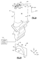
Figure 2A is a perspective view of the airfoil having the disclosed squealer pockets. -
Figure 2B is a plan view of the airfoil illustrating directional references. -
Figure 3 is a perspective view of a core used to produce correspondingly shaped cooling passages in the airfoil illustrated inFigure 2A . -
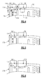
Figure 4 is a cross-sectional view of one example airfoil with multiple squealer pockets. -
Figure 5 is a cross-sectional view of another example airfoil with multiple squealer pockets. -
Figure 6 is a cross-sectional view of still another example airfoil with multiple squealer pockets. - The embodiments, examples and alternatives of the preceding paragraphs, the claims, or the following description and drawings, including any of their various aspects or respective individual features, may be taken independently or in any combination. Features described in connection with one embodiment are applicable to all embodiments, unless such features are incompatible.
-
Figure 1 schematically illustrates agas turbine engine 20. Thegas turbine engine 20 is disclosed herein as a two-spool turbofan that generally incorporates afan section 22, acompressor section 24, acombustor section 26 and aturbine section 28. Alternative engines might include an augmenter section (not shown) among other systems or features. Thefan section 22 drives air along a bypass flow path B in a bypass duct defined within anacelle 15, while thecompressor section 24 drives air along a core flow path C for compression and communication into thecombustor section 26 then expansion through theturbine section 28. Although depicted as a two-spool turbofan gas turbine engine in the disclosed non-limiting embodiment, it should be understood that the concepts described herein are not limited to use with two-spool turbofans as the teachings may be applied to other types of turbine engines including three-spool architectures. - The
exemplary engine 20 generally includes alow speed spool 30 and ahigh speed spool 32 mounted for rotation about an engine central longitudinal axis X relative to an enginestatic structure 36 viaseveral bearing systems 38. It should be understood thatvarious bearing systems 38 at various locations may alternatively or additionally be provided, and the location ofbearing systems 38 may be varied as appropriate to the application. - The
low speed spool 30 generally includes aninner shaft 40 that interconnects afan 42, a first (or low)pressure compressor 44 and a first (or low)pressure turbine 46. Theinner shaft 40 is connected to thefan 42 through a speed change mechanism, which in exemplarygas turbine engine 20 is illustrated as a gearedarchitecture 48 to drive thefan 42 at a lower speed than thelow speed spool 30. Thehigh speed spool 32 includes anouter shaft 50 that interconnects a second (or high)pressure compressor 52 and a second (or high)pressure turbine 54. Acombustor 56 is arranged inexemplary gas turbine 20 between thehigh pressure compressor 52 and thehigh pressure turbine 54. Amid-turbine frame 57 of the enginestatic structure 36 is arranged generally between thehigh pressure turbine 54 and thelow pressure turbine 46. Themid-turbine frame 57 furthersupports bearing systems 38 in theturbine section 28. Theinner shaft 40 and theouter shaft 50 are concentric and rotate via bearingsystems 38 about the engine central longitudinal axis X which is collinear with their longitudinal axes. - The core airflow is compressed by the
low pressure compressor 44 then thehigh pressure compressor 52, mixed and burned with fuel in thecombustor 56, then expanded over thehigh pressure turbine 54 andlow pressure turbine 46. Themid-turbine frame 57 includesairfoils 59 which are in the core airflow path C. Theturbines low speed spool 30 andhigh speed spool 32 in response to the expansion. It will be appreciated that each of the positions of thefan section 22,compressor section 24,combustor section 26,turbine section 28, and fandrive gear system 48 may be varied. For example,gear system 48 may be located aft ofcombustor section 26 or even aft ofturbine section 28, andfan section 22 may be positioned forward or aft of the location ofgear system 48. - The
engine 20 in one example is a high-bypass geared aircraft engine. In a further example, theengine 20 bypass ratio is greater than about six (6), with an example embodiment being greater than about ten (10), the gearedarchitecture 48 is an epicyclic gear train, such as a planetary gear system or other gear system, with a gear reduction ratio of greater than about 2.3 and thelow pressure turbine 46 has a pressure ratio that is greater than about five. In one disclosed embodiment, theengine 20 bypass ratio is greater than about ten (10:1), the fan diameter is significantly larger than that of thelow pressure compressor 44, and thelow pressure turbine 46 has a pressure ratio that is greater than about five (5:1).Low pressure turbine 46 pressure ratio is pressure measured prior to inlet oflow pressure turbine 46 as related to the pressure at the outlet of thelow pressure turbine 46 prior to an exhaust nozzle. The gearedarchitecture 48 may be an epicyclic gear train, such as a planetary gear system or other gear system, with a gear reduction ratio of greater than about 2.3:1. It should be understood, however, that the above parameters are only exemplary of one embodiment of a geared architecture engine and that the present invention is applicable to other gas turbine engines including direct drive turbofans. - A significant amount of thrust is provided by the bypass flow B due to the high bypass ratio. The
fan section 22 of theengine 20 is designed for a particular flight condition - typically cruise at about 0.8 Mach and about 35,000 feet (10,700 meters). The flight condition of 0.8 Mach and 35,000 ft (10,700 meters), with the engine at its best fuel consumption - also known as "bucket cruise Thrust Specific Fuel Consumption ('TSFC')" - is the industry standard parameter of Ibm of fuel being burned divided by Ibf of thrust the engine produces at that minimum point. "Low fan pressure ratio" is the pressure ratio across the fan blade alone, without a Fan Exit Guide Vane ("FEGV") system. The low fan pressure ratio as disclosed herein according to one non-limiting embodiment is less than about 1.45. "Low corrected fan tip speed" is the actual fan tip speed in ft/sec divided by an industry standard temperature correction of [(Tram °R) / (518.7 °R)]0.5. The "Low corrected fan tip speed" as disclosed herein according to one non-limiting embodiment is less than about 1150 ft / second (350 meters/second). - Referring to
Figures 2A and 2B , aroot 74 of eachturbine blade 64 is mounted to the rotor disk (not shown). The disclosed airfoil may also be used in a compressor section. Theturbine blade 64 includes aplatform 76, which provides the inner flow path, supported by theroot 74. Anairfoil 78 extends in a radial direction R from theplatform 76 to atip 80. It should be understood that the turbine blades may be integrally formed with the rotor such that the roots are eliminated. In such a configuration, the platform is provided by the outer diameter of the rotor. Theairfoil 78 provides leading and trailingedges tip 80 is arranged adjacent to a bladeouter air seal 89, which provide the outer flow path. - The
airfoil 78 ofFigure 2B somewhat schematically illustrates exterior airfoil surface extending in a chord-wise direction C between aleading edge 82 to a trailingedge 84. Theairfoil 78 is provided between pressure (typically concave) and suction (typically convex)wall Multiple turbine blades 64 are arranged circumferentially in a circumferential direction A. Theairfoil 78 extends from theplatform 76 in the radial direction R, or spanwise, to thetip 80. - The
airfoil 78 includes one or more cooling passages provided between the pressure andsuction walls airfoil 78 may be formed by any suitable process. - Referring to
Figure 2A , thetip 80 of theairfoil 78 includes aterminal end surface 90 that is arranged adjacent to a bladeouter air seal 89 during engine operation. Multiple squealer pockets 92, 94 are provided in theterminal end surface 90. In the example, aperimeter wall 95 circumscribes thetip 80. Although two squealer pockets are shown, more than two pockets may be provided in thetip 80. The squealer pockets 92, 94 are arranged interiorly of and surrounded by theperimeter wall 95. Anintermediate wall 96 interconnects opposing sides of theperimeter wall 95 to separate the adjoining squealer pockets 92, 94. Theintermediate wall 96 extends in the thickness direction T in the example. The airfoil may be provided in the compressor and/or turbine sections. - Cooling holes 98 fluidly interconnect the squealer pockets 92, 94 to cooling passages arranged internally within the
airfoil 78. The cooling passages are formed by a correspondingly shapedcore 112, which is shown inFigure 3 . The shaded portion of thecore 112 represents a portion that extends beyond thetip 80 during the casting process. The cooling passages formed by thiscore 112 are supplied a cooling fluid from acooling source 102, which may be provided by compressor bleed air.Example cooling passages Figure 4 . It should be understood that any suitable configuration of cooling passages may be provided in theairfoil 78 based upon the particular blade application. - In the example, the squealer pockets 92, 94 have a depth of at least 20 mils (0.50 mm). The squealer pockets 92, 94 are arranged in areas of the
tip 80 in which a boundary of cooling fluid is desired, such as near the leading edge 82 (e.g., the squealer pocket 92). In the example, thesquealer pocket 94 is arranged adjacent to thesquealer pocket 92, although thesquealer pocket 94 may be spaced from, or remote from, thesquealer pocket 92, for example, near the trailingedge 84. - The
intermediate wall 96 maintains the cooling fluid within the forward squealer pocket, for example, to prevent migration of the cooling fluid to areas where it is not needed, such as more aftwardly located regions of thetip 80. Other features also may be used to maintain the cooling fluid where desired. For example, referring toFigure 4 , thesquealer pocket 92 includes a steppedbottom surface 118 having first andsecond depths first depth 114 is larger than thesecond depth 116 and located near the leading edge to better retain the cooling fluid near the leading edge. - Another example
squealer pocket configuration 192 of anairfoil 178 is shown inFigure 5 in which thesquealer pocket 192 has abottom surface 120 that provides a generally uniform depth to thesquealer pocket 192. The bottom may be flat or be curved to match the curvature of the blade tip. - The
example airfoil 278 shown inFigure 6 illustrates a forward slopedsurface 122 that provides a decreased depth near the leading edge than a more aftward located portion of thesquealer pocket 292. Squealer pockets having geometries other than shown may be used if desired. Thesquealer pocket 194 may be deeper than thesquealer pocket 292, if desired. - A desired amount of cooling fluid is provided to the
squealer pocket 92. A different amount of cooling fluid may be provided to thesecond squealer pocket 94, in one example. Thus, more cooling fluid may be provided to thesquealer pocket 92 near the leading edge, for example, where more cooling fluid is typically desired due to the hotter temperatures under which the leading edge operates. - It should also be understood that although a particular component arrangement is disclosed in the illustrated embodiment, other arrangements will benefit herefrom. Although particular step sequences are shown, described, and claimed, it should be understood that steps may be performed in any order, separated or combined unless otherwise indicated and will still benefit from the present invention.
- Although the different examples have specific components shown in the illustrations, embodiments of this invention are not limited to those particular combinations. It is possible to use some of the components or features from one of the examples in combination with features or components from another one of the examples.
- Although an example embodiment has been disclosed, a worker of ordinary skill in this art would recognize that certain modifications would come within the scope of the claims. For that reason, the following claims should be studied to determine their true scope and content.
Claims (14)
- A blade for a gas turbine engine comprising:an airfoil having a tip with a terminal end surface, and multiple squealer pockets recessed into the terminal end surface.
- The blade according to claim 1, wherein the terminal end surface provides a perimeter wall circumscribing the tip, the squealer pockets arranged interiorly of the perimeter wall.
- The blade according to claim 2, wherein the tip includes at least one intermediate wall interconnecting opposing sides of the perimeter wall and separating adjoining squealer pockets.
- The blade according to claim 3, wherein the intermediate wall extends in a thickness direction between pressure and suction sides of the airfoil.
- The blade according to any preceding claim, wherein the airfoil includes at least one cooling passage arranged interiorly, and cooling holes fluidly connect the at least one cooling passage to the squealer pockets.
- The blade according to any preceding claim, wherein the squealer pockets have a depth of at least 20 mils (0.50 mm).
- The blade according to any preceding claim, wherein one of the squealer pockets is arranged near the leading edge.
- The blade according to claim 7, wherein the one of the squealer pocket has a first depth near the leading edge that is different than a second depth located aftward of the first depth.
- A gas turbine engine comprising:compressor and turbine sections; anda blade as claimed in any preceding claim provided in one of the compressor and turbine sections.
- The gas turbine engine according to claim 9, wherein the turbine section includes a turbine blade having the airfoil.
- A method of cooling a blade comprising the steps of:providing cooling fluid to a first squealer pocket in an airfoil tip; andproviding cooling fluid to a second squealer pocket in the airfoil tip in an amount that is different than that provided to the first squealer pocket.
- The method according to claim 11, wherein the first and second squealer pockets are arranged adjacent to one another.
- The method according to claim 11 or claim 12, wherein the first squealer pocket is arranged near an airfoil leading edge.
- The method according to any of claims 11 to 13, wherein the first squealer pocket is provided more cooling fluid than the second squealer pocket.
Applications Claiming Priority (1)
| Application Number | Priority Date | Filing Date | Title |
|---|---|---|---|
| US201461990153P | 2014-05-08 | 2014-05-08 |
Publications (2)
| Publication Number | Publication Date |
|---|---|
| EP2942488A1 true EP2942488A1 (en) | 2015-11-11 |
| EP2942488B1 EP2942488B1 (en) | 2023-04-26 |
Family
ID=53016544
Family Applications (1)
| Application Number | Title | Priority Date | Filing Date |
|---|---|---|---|
| EP15165906.7A Active EP2942488B1 (en) | 2014-05-08 | 2015-04-30 | Blade for a gas turbine engine, gas turbine engine and method of cooling a blade for a gas turbine engine |
Country Status (2)
| Country | Link |
|---|---|
| US (1) | US10041358B2 (en) |
| EP (1) | EP2942488B1 (en) |
Cited By (8)
| Publication number | Priority date | Publication date | Assignee | Title |
|---|---|---|---|---|
| US20180156042A1 (en) | 2016-12-05 | 2018-06-07 | United Technologies Corporation | Integrated squealer pocket tip and tip shelf with hybrid and tip flag core |
| EP3382152A1 (en) * | 2017-03-28 | 2018-10-03 | United Technologies Corporation | Blade tip cooling design |
| US10465529B2 (en) | 2016-12-05 | 2019-11-05 | United Technologies Corporation | Leading edge hybrid cavities and cores for airfoils of gas turbine engine |
| CN110566284A (en) * | 2019-10-09 | 2019-12-13 | 西北工业大学 | A grooved blade top structure with barrier ribs |
| US10563521B2 (en) | 2016-12-05 | 2020-02-18 | United Technologies Corporation | Aft flowing serpentine cavities and cores for airfoils of gas turbine engines |
| US10815800B2 (en) | 2016-12-05 | 2020-10-27 | Raytheon Technologies Corporation | Radially diffused tip flag |
| EP3808941A1 (en) * | 2019-10-16 | 2021-04-21 | Raytheon Technologies Corporation | Angled tip rods in a casting core for a turbine blade |
| US11773726B2 (en) | 2019-10-16 | 2023-10-03 | Rtx Corporation | Angled tip rods |
Families Citing this family (4)
| Publication number | Priority date | Publication date | Assignee | Title |
|---|---|---|---|---|
| FR3027951B1 (en) * | 2014-11-04 | 2019-12-13 | Safran Aircraft Engines | BATH OF SUMMIT OF DAWN OF A TURBINE OF TURBOMACHINE |
| US11021967B2 (en) * | 2017-04-03 | 2021-06-01 | General Electric Company | Turbine engine component with a core tie hole |
| US10941663B2 (en) * | 2018-05-07 | 2021-03-09 | Raytheon Technologies Corporation | Airfoil having improved leading edge cooling scheme and damage resistance |
| US10907479B2 (en) * | 2018-05-07 | 2021-02-02 | Raytheon Technologies Corporation | Airfoil having improved leading edge cooling scheme and damage resistance |
Citations (2)
| Publication number | Priority date | Publication date | Assignee | Title |
|---|---|---|---|---|
| GB2105415A (en) * | 1981-09-02 | 1983-03-23 | Westinghouse Electric Corp | Air-cooled turbine rotor blade with trailing edge recessed holes |
| EP2716870A1 (en) * | 2012-10-05 | 2014-04-09 | General Electric Company | Rotor blade, corresponding turbine and method for cooling a rotor blade |
Family Cites Families (10)
| Publication number | Priority date | Publication date | Assignee | Title |
|---|---|---|---|---|
| US3854842A (en) * | 1973-04-30 | 1974-12-17 | Gen Electric | Rotor blade having improved tip cap |
| US4010531A (en) * | 1975-09-02 | 1977-03-08 | General Electric Company | Tip cap apparatus and method of installation |
| US5183385A (en) | 1990-11-19 | 1993-02-02 | General Electric Company | Turbine blade squealer tip having air cooling holes contiguous with tip interior wall surface |
| US6672829B1 (en) | 2002-07-16 | 2004-01-06 | General Electric Company | Turbine blade having angled squealer tip |
| US7270514B2 (en) | 2004-10-21 | 2007-09-18 | General Electric Company | Turbine blade tip squealer and rebuild method |
| US8512003B2 (en) * | 2006-08-21 | 2013-08-20 | General Electric Company | Tip ramp turbine blade |
| US8425183B2 (en) * | 2006-11-20 | 2013-04-23 | General Electric Company | Triforial tip cavity airfoil |
| US8167572B2 (en) | 2008-07-14 | 2012-05-01 | Pratt & Whitney Canada Corp. | Dynamically tuned turbine blade growth pocket |
| US8092178B2 (en) | 2008-11-28 | 2012-01-10 | Pratt & Whitney Canada Corp. | Turbine blade for a gas turbine engine |
| US8313287B2 (en) | 2009-06-17 | 2012-11-20 | Siemens Energy, Inc. | Turbine blade squealer tip rail with fence members |
-
2015
- 2015-04-27 US US14/696,601 patent/US10041358B2/en active Active
- 2015-04-30 EP EP15165906.7A patent/EP2942488B1/en active Active
Patent Citations (2)
| Publication number | Priority date | Publication date | Assignee | Title |
|---|---|---|---|---|
| GB2105415A (en) * | 1981-09-02 | 1983-03-23 | Westinghouse Electric Corp | Air-cooled turbine rotor blade with trailing edge recessed holes |
| EP2716870A1 (en) * | 2012-10-05 | 2014-04-09 | General Electric Company | Rotor blade, corresponding turbine and method for cooling a rotor blade |
Cited By (13)
| Publication number | Priority date | Publication date | Assignee | Title |
|---|---|---|---|---|
| US10815800B2 (en) | 2016-12-05 | 2020-10-27 | Raytheon Technologies Corporation | Radially diffused tip flag |
| EP3342978A3 (en) * | 2016-12-05 | 2018-08-01 | United Technologies Corporation | Integrated squealer pocket tip and tip shelf with hybrid and tip flag core |
| US10465529B2 (en) | 2016-12-05 | 2019-11-05 | United Technologies Corporation | Leading edge hybrid cavities and cores for airfoils of gas turbine engine |
| US10563521B2 (en) | 2016-12-05 | 2020-02-18 | United Technologies Corporation | Aft flowing serpentine cavities and cores for airfoils of gas turbine engines |
| US20180156042A1 (en) | 2016-12-05 | 2018-06-07 | United Technologies Corporation | Integrated squealer pocket tip and tip shelf with hybrid and tip flag core |
| US10989056B2 (en) | 2016-12-05 | 2021-04-27 | Raytheon Technologies Corporation | Integrated squealer pocket tip and tip shelf with hybrid and tip flag core |
| US11725521B2 (en) | 2016-12-05 | 2023-08-15 | Raytheon Technologies Corporation | Leading edge hybrid cavities for airfoils of gas turbine engine |
| EP3382152A1 (en) * | 2017-03-28 | 2018-10-03 | United Technologies Corporation | Blade tip cooling design |
| US11434770B2 (en) | 2017-03-28 | 2022-09-06 | Raytheon Technologies Corporation | Tip cooling design |
| CN110566284A (en) * | 2019-10-09 | 2019-12-13 | 西北工业大学 | A grooved blade top structure with barrier ribs |
| EP3808941A1 (en) * | 2019-10-16 | 2021-04-21 | Raytheon Technologies Corporation | Angled tip rods in a casting core for a turbine blade |
| US11143035B2 (en) | 2019-10-16 | 2021-10-12 | Raytheon Technologies Corporation | Angled tip rods |
| US11773726B2 (en) | 2019-10-16 | 2023-10-03 | Rtx Corporation | Angled tip rods |
Also Published As
| Publication number | Publication date |
|---|---|
| US20160017719A1 (en) | 2016-01-21 |
| EP2942488B1 (en) | 2023-04-26 |
| US10041358B2 (en) | 2018-08-07 |
Similar Documents
| Publication | Publication Date | Title |
|---|---|---|
| EP2942488B1 (en) | Blade for a gas turbine engine, gas turbine engine and method of cooling a blade for a gas turbine engine | |
| US11148191B2 (en) | Core arrangement for turbine engine component | |
| EP2944764B1 (en) | Gas turbine engine component, corresponding gas turbine engine and method of cooling | |
| EP3009599A1 (en) | Gas turbine engine component with film cooling hole feature | |
| EP3043027B1 (en) | Gas turbine engine component with conformal fillet cooling path | |
| US10975705B2 (en) | Gas turbine engine airfoil with wishbone baffle cooling scheme | |
| EP3081753A1 (en) | Blade tip cooling arrangement | |
| EP2993304B1 (en) | Gas turbine engine component with film cooling hole | |
| EP4397841A2 (en) | Gas turbine engine airfoil turbulator for airfoil creep resistance | |
| EP2975215A1 (en) | Method of creating heat transfer features in high temperature alloys | |
| EP2993303B1 (en) | Gas turbine engine component with film cooling hole with pocket | |
| EP3112596A1 (en) | Gas turbine engine airfoil with bi-axial skin cooling passage and corresponding gas turbine engine | |
| EP3461993A1 (en) | Gas turbine engine airfoil | |
| EP3009600A1 (en) | Gas turbine engine turbine blade with cooled tip | |
| EP3045666B1 (en) | Airfoil platform with cooling feed orifices | |
| US10794207B2 (en) | Gas turbine engine airfoil component platform seal cooling | |
| EP3039247B1 (en) | Gas turbine engine airfoil crossover and pedestal rib cooling arrangement | |
| EP3059391A1 (en) | Gas turbine engine turbine blade cooling using upstream stator vane | |
| EP3061913B1 (en) | Gas turbine engine airfoil cooling configuration with pressure gradient separators | |
| EP2929955A1 (en) | Rib bumper system | |
| EP2942486B1 (en) | Gas turbine engine airfoil cooling passage configuration | |
| EP3477055A1 (en) | Gas turbine engine airfoil |
Legal Events
| Date | Code | Title | Description |
|---|---|---|---|
| PUAI | Public reference made under article 153(3) epc to a published international application that has entered the european phase |
Free format text: ORIGINAL CODE: 0009012 |
|
| AK | Designated contracting states |
Kind code of ref document: A1 Designated state(s): AL AT BE BG CH CY CZ DE DK EE ES FI FR GB GR HR HU IE IS IT LI LT LU LV MC MK MT NL NO PL PT RO RS SE SI SK SM TR |
|
| AX | Request for extension of the european patent |
Extension state: BA ME |
|
| 17P | Request for examination filed |
Effective date: 20160505 |
|
| RBV | Designated contracting states (corrected) |
Designated state(s): AL AT BE BG CH CY CZ DE DK EE ES FI FR GB GR HR HU IE IS IT LI LT LU LV MC MK MT NL NO PL PT RO RS SE SI SK SM TR |
|
| RAP1 | Party data changed (applicant data changed or rights of an application transferred) |
Owner name: UNITED TECHNOLOGIES CORPORATION |
|
| STAA | Information on the status of an ep patent application or granted ep patent |
Free format text: STATUS: EXAMINATION IS IN PROGRESS |
|
| 17Q | First examination report despatched |
Effective date: 20200204 |
|
| RAP1 | Party data changed (applicant data changed or rights of an application transferred) |
Owner name: RAYTHEON TECHNOLOGIES CORPORATION |
|
| GRAP | Despatch of communication of intention to grant a patent |
Free format text: ORIGINAL CODE: EPIDOSNIGR1 |
|
| STAA | Information on the status of an ep patent application or granted ep patent |
Free format text: STATUS: GRANT OF PATENT IS INTENDED |
|
| GRAS | Grant fee paid |
Free format text: ORIGINAL CODE: EPIDOSNIGR3 |
|
| INTG | Intention to grant announced |
Effective date: 20230214 |
|
| GRAA | (expected) grant |
Free format text: ORIGINAL CODE: 0009210 |
|
| STAA | Information on the status of an ep patent application or granted ep patent |
Free format text: STATUS: THE PATENT HAS BEEN GRANTED |
|
| AK | Designated contracting states |
Kind code of ref document: B1 Designated state(s): AL AT BE BG CH CY CZ DE DK EE ES FI FR GB GR HR HU IE IS IT LI LT LU LV MC MK MT NL NO PL PT RO RS SE SI SK SM TR |
|
| REG | Reference to a national code |
Ref country code: GB Ref legal event code: FG4D |
|
| REG | Reference to a national code |
Ref country code: CH Ref legal event code: EP |
|
| REG | Reference to a national code |
Ref country code: DE Ref legal event code: R096 Ref document number: 602015083281 Country of ref document: DE |
|
| REG | Reference to a national code |
Ref country code: AT Ref legal event code: REF Ref document number: 1562949 Country of ref document: AT Kind code of ref document: T Effective date: 20230515 |
|
| REG | Reference to a national code |
Ref country code: IE Ref legal event code: FG4D |
|
| P01 | Opt-out of the competence of the unified patent court (upc) registered |
Effective date: 20230603 |
|
| REG | Reference to a national code |
Ref country code: LT Ref legal event code: MG9D |
|
| REG | Reference to a national code |
Ref country code: NL Ref legal event code: MP Effective date: 20230426 |
|
| REG | Reference to a national code |
Ref country code: AT Ref legal event code: MK05 Ref document number: 1562949 Country of ref document: AT Kind code of ref document: T Effective date: 20230426 |
|
| PG25 | Lapsed in a contracting state [announced via postgrant information from national office to epo] |
Ref country code: NL Free format text: LAPSE BECAUSE OF FAILURE TO SUBMIT A TRANSLATION OF THE DESCRIPTION OR TO PAY THE FEE WITHIN THE PRESCRIBED TIME-LIMIT Effective date: 20230426 |
|
| PG25 | Lapsed in a contracting state [announced via postgrant information from national office to epo] |
Ref country code: SE Free format text: LAPSE BECAUSE OF FAILURE TO SUBMIT A TRANSLATION OF THE DESCRIPTION OR TO PAY THE FEE WITHIN THE PRESCRIBED TIME-LIMIT Effective date: 20230426 Ref country code: PT Free format text: LAPSE BECAUSE OF FAILURE TO SUBMIT A TRANSLATION OF THE DESCRIPTION OR TO PAY THE FEE WITHIN THE PRESCRIBED TIME-LIMIT Effective date: 20230828 Ref country code: NO Free format text: LAPSE BECAUSE OF FAILURE TO SUBMIT A TRANSLATION OF THE DESCRIPTION OR TO PAY THE FEE WITHIN THE PRESCRIBED TIME-LIMIT Effective date: 20230726 Ref country code: ES Free format text: LAPSE BECAUSE OF FAILURE TO SUBMIT A TRANSLATION OF THE DESCRIPTION OR TO PAY THE FEE WITHIN THE PRESCRIBED TIME-LIMIT Effective date: 20230426 Ref country code: AT Free format text: LAPSE BECAUSE OF FAILURE TO SUBMIT A TRANSLATION OF THE DESCRIPTION OR TO PAY THE FEE WITHIN THE PRESCRIBED TIME-LIMIT Effective date: 20230426 |
|
| RAP4 | Party data changed (patent owner data changed or rights of a patent transferred) |
Owner name: RTX CORPORATION |
|
| PG25 | Lapsed in a contracting state [announced via postgrant information from national office to epo] |
Ref country code: RS Free format text: LAPSE BECAUSE OF FAILURE TO SUBMIT A TRANSLATION OF THE DESCRIPTION OR TO PAY THE FEE WITHIN THE PRESCRIBED TIME-LIMIT Effective date: 20230426 Ref country code: PL Free format text: LAPSE BECAUSE OF FAILURE TO SUBMIT A TRANSLATION OF THE DESCRIPTION OR TO PAY THE FEE WITHIN THE PRESCRIBED TIME-LIMIT Effective date: 20230426 Ref country code: LV Free format text: LAPSE BECAUSE OF FAILURE TO SUBMIT A TRANSLATION OF THE DESCRIPTION OR TO PAY THE FEE WITHIN THE PRESCRIBED TIME-LIMIT Effective date: 20230426 Ref country code: LT Free format text: LAPSE BECAUSE OF FAILURE TO SUBMIT A TRANSLATION OF THE DESCRIPTION OR TO PAY THE FEE WITHIN THE PRESCRIBED TIME-LIMIT Effective date: 20230426 Ref country code: IS Free format text: LAPSE BECAUSE OF FAILURE TO SUBMIT A TRANSLATION OF THE DESCRIPTION OR TO PAY THE FEE WITHIN THE PRESCRIBED TIME-LIMIT Effective date: 20230826 Ref country code: HR Free format text: LAPSE BECAUSE OF FAILURE TO SUBMIT A TRANSLATION OF THE DESCRIPTION OR TO PAY THE FEE WITHIN THE PRESCRIBED TIME-LIMIT Effective date: 20230426 Ref country code: GR Free format text: LAPSE BECAUSE OF FAILURE TO SUBMIT A TRANSLATION OF THE DESCRIPTION OR TO PAY THE FEE WITHIN THE PRESCRIBED TIME-LIMIT Effective date: 20230727 |
|
| REG | Reference to a national code |
Ref country code: CH Ref legal event code: PL |
|
| PG25 | Lapsed in a contracting state [announced via postgrant information from national office to epo] |
Ref country code: LU Free format text: LAPSE BECAUSE OF NON-PAYMENT OF DUE FEES Effective date: 20230430 Ref country code: FI Free format text: LAPSE BECAUSE OF FAILURE TO SUBMIT A TRANSLATION OF THE DESCRIPTION OR TO PAY THE FEE WITHIN THE PRESCRIBED TIME-LIMIT Effective date: 20230426 |
|
| REG | Reference to a national code |
Ref country code: BE Ref legal event code: MM Effective date: 20230430 |
|
| PG25 | Lapsed in a contracting state [announced via postgrant information from national office to epo] |
Ref country code: SK Free format text: LAPSE BECAUSE OF FAILURE TO SUBMIT A TRANSLATION OF THE DESCRIPTION OR TO PAY THE FEE WITHIN THE PRESCRIBED TIME-LIMIT Effective date: 20230426 |
|
| PG25 | Lapsed in a contracting state [announced via postgrant information from national office to epo] |
Ref country code: MC Free format text: LAPSE BECAUSE OF FAILURE TO SUBMIT A TRANSLATION OF THE DESCRIPTION OR TO PAY THE FEE WITHIN THE PRESCRIBED TIME-LIMIT Effective date: 20230426 |
|
| REG | Reference to a national code |
Ref country code: DE Ref legal event code: R097 Ref document number: 602015083281 Country of ref document: DE |
|
| PG25 | Lapsed in a contracting state [announced via postgrant information from national office to epo] |
Ref country code: SM Free format text: LAPSE BECAUSE OF FAILURE TO SUBMIT A TRANSLATION OF THE DESCRIPTION OR TO PAY THE FEE WITHIN THE PRESCRIBED TIME-LIMIT Effective date: 20230426 Ref country code: SK Free format text: LAPSE BECAUSE OF FAILURE TO SUBMIT A TRANSLATION OF THE DESCRIPTION OR TO PAY THE FEE WITHIN THE PRESCRIBED TIME-LIMIT Effective date: 20230426 Ref country code: RO Free format text: LAPSE BECAUSE OF FAILURE TO SUBMIT A TRANSLATION OF THE DESCRIPTION OR TO PAY THE FEE WITHIN THE PRESCRIBED TIME-LIMIT Effective date: 20230426 Ref country code: MC Free format text: LAPSE BECAUSE OF FAILURE TO SUBMIT A TRANSLATION OF THE DESCRIPTION OR TO PAY THE FEE WITHIN THE PRESCRIBED TIME-LIMIT Effective date: 20230426 Ref country code: LI Free format text: LAPSE BECAUSE OF NON-PAYMENT OF DUE FEES Effective date: 20230430 Ref country code: EE Free format text: LAPSE BECAUSE OF FAILURE TO SUBMIT A TRANSLATION OF THE DESCRIPTION OR TO PAY THE FEE WITHIN THE PRESCRIBED TIME-LIMIT Effective date: 20230426 Ref country code: DK Free format text: LAPSE BECAUSE OF FAILURE TO SUBMIT A TRANSLATION OF THE DESCRIPTION OR TO PAY THE FEE WITHIN THE PRESCRIBED TIME-LIMIT Effective date: 20230426 Ref country code: CZ Free format text: LAPSE BECAUSE OF FAILURE TO SUBMIT A TRANSLATION OF THE DESCRIPTION OR TO PAY THE FEE WITHIN THE PRESCRIBED TIME-LIMIT Effective date: 20230426 Ref country code: CH Free format text: LAPSE BECAUSE OF NON-PAYMENT OF DUE FEES Effective date: 20230430 |
|
| REG | Reference to a national code |
Ref country code: IE Ref legal event code: MM4A |
|
| PG25 | Lapsed in a contracting state [announced via postgrant information from national office to epo] |
Ref country code: BE Free format text: LAPSE BECAUSE OF NON-PAYMENT OF DUE FEES Effective date: 20230430 |
|
| PLBE | No opposition filed within time limit |
Free format text: ORIGINAL CODE: 0009261 |
|
| STAA | Information on the status of an ep patent application or granted ep patent |
Free format text: STATUS: NO OPPOSITION FILED WITHIN TIME LIMIT |
|
| 26N | No opposition filed |
Effective date: 20240129 |
|
| PG25 | Lapsed in a contracting state [announced via postgrant information from national office to epo] |
Ref country code: IE Free format text: LAPSE BECAUSE OF NON-PAYMENT OF DUE FEES Effective date: 20230430 |
|
| PG25 | Lapsed in a contracting state [announced via postgrant information from national office to epo] |
Ref country code: IE Free format text: LAPSE BECAUSE OF NON-PAYMENT OF DUE FEES Effective date: 20230430 |
|
| PG25 | Lapsed in a contracting state [announced via postgrant information from national office to epo] |
Ref country code: SI Free format text: LAPSE BECAUSE OF FAILURE TO SUBMIT A TRANSLATION OF THE DESCRIPTION OR TO PAY THE FEE WITHIN THE PRESCRIBED TIME-LIMIT Effective date: 20230426 |
|
| PG25 | Lapsed in a contracting state [announced via postgrant information from national office to epo] |
Ref country code: SI Free format text: LAPSE BECAUSE OF FAILURE TO SUBMIT A TRANSLATION OF THE DESCRIPTION OR TO PAY THE FEE WITHIN THE PRESCRIBED TIME-LIMIT Effective date: 20230426 Ref country code: IT Free format text: LAPSE BECAUSE OF FAILURE TO SUBMIT A TRANSLATION OF THE DESCRIPTION OR TO PAY THE FEE WITHIN THE PRESCRIBED TIME-LIMIT Effective date: 20230426 |
|
| PG25 | Lapsed in a contracting state [announced via postgrant information from national office to epo] |
Ref country code: BG Free format text: LAPSE BECAUSE OF FAILURE TO SUBMIT A TRANSLATION OF THE DESCRIPTION OR TO PAY THE FEE WITHIN THE PRESCRIBED TIME-LIMIT Effective date: 20230426 |
|
| PG25 | Lapsed in a contracting state [announced via postgrant information from national office to epo] |
Ref country code: BG Free format text: LAPSE BECAUSE OF FAILURE TO SUBMIT A TRANSLATION OF THE DESCRIPTION OR TO PAY THE FEE WITHIN THE PRESCRIBED TIME-LIMIT Effective date: 20230426 |
|
| PGFP | Annual fee paid to national office [announced via postgrant information from national office to epo] |
Ref country code: DE Payment date: 20250319 Year of fee payment: 11 |
|
| PG25 | Lapsed in a contracting state [announced via postgrant information from national office to epo] |
Ref country code: CY Free format text: LAPSE BECAUSE OF FAILURE TO SUBMIT A TRANSLATION OF THE DESCRIPTION OR TO PAY THE FEE WITHIN THE PRESCRIBED TIME-LIMIT; INVALID AB INITIO Effective date: 20150430 |
|
| PG25 | Lapsed in a contracting state [announced via postgrant information from national office to epo] |
Ref country code: HU Free format text: LAPSE BECAUSE OF FAILURE TO SUBMIT A TRANSLATION OF THE DESCRIPTION OR TO PAY THE FEE WITHIN THE PRESCRIBED TIME-LIMIT; INVALID AB INITIO Effective date: 20150430 |
|
| REG | Reference to a national code |
Ref country code: DE Ref legal event code: R081 Ref document number: 602015083281 Country of ref document: DE Owner name: RTX CORPORATION (N.D.GES.D. STAATES DELAWARE),, US Free format text: FORMER OWNER: RAYTHEON TECHNOLOGIES CORPORATION, FARMINGTON, CT, US |
|
| PG25 | Lapsed in a contracting state [announced via postgrant information from national office to epo] |
Ref country code: TR Free format text: LAPSE BECAUSE OF FAILURE TO SUBMIT A TRANSLATION OF THE DESCRIPTION OR TO PAY THE FEE WITHIN THE PRESCRIBED TIME-LIMIT Effective date: 20230426 |
|
| PGFP | Annual fee paid to national office [announced via postgrant information from national office to epo] |
Ref country code: GB Payment date: 20260319 Year of fee payment: 12 |
|
| PGFP | Annual fee paid to national office [announced via postgrant information from national office to epo] |
Ref country code: FR Payment date: 20260320 Year of fee payment: 12 |