EP2942479A1 - Apparatus and method for inspecting a turbine blade tip shroud - Google Patents
Apparatus and method for inspecting a turbine blade tip shroud Download PDFInfo
- Publication number
- EP2942479A1 EP2942479A1 EP15165237.7A EP15165237A EP2942479A1 EP 2942479 A1 EP2942479 A1 EP 2942479A1 EP 15165237 A EP15165237 A EP 15165237A EP 2942479 A1 EP2942479 A1 EP 2942479A1
- Authority
- EP
- European Patent Office
- Prior art keywords
- notch
- tip shroud
- turbine blade
- blade tip
- frame
- Prior art date
- Legal status (The legal status is an assumption and is not a legal conclusion. Google has not performed a legal analysis and makes no representation as to the accuracy of the status listed.)
- Granted
Links
- 238000000034 method Methods 0.000 title claims description 25
- 238000007689 inspection Methods 0.000 claims abstract description 71
- 239000012530 fluid Substances 0.000 description 8
- 239000000463 material Substances 0.000 description 7
- 230000004048 modification Effects 0.000 description 7
- 238000012986 modification Methods 0.000 description 7
- 238000003908 quality control method Methods 0.000 description 3
- 238000013461 design Methods 0.000 description 2
- 238000009434 installation Methods 0.000 description 2
- 238000002156 mixing Methods 0.000 description 2
- 230000008439 repair process Effects 0.000 description 2
- 238000011144 upstream manufacturing Methods 0.000 description 2
- 230000000007 visual effect Effects 0.000 description 2
- 239000000567 combustion gas Substances 0.000 description 1
- 230000000295 complement effect Effects 0.000 description 1
- 238000010586 diagram Methods 0.000 description 1
- 230000003628 erosive effect Effects 0.000 description 1
- 239000011152 fibreglass Substances 0.000 description 1
- 230000006870 function Effects 0.000 description 1
- 239000007789 gas Substances 0.000 description 1
- 238000004519 manufacturing process Methods 0.000 description 1
- 238000013507 mapping Methods 0.000 description 1
- 238000005259 measurement Methods 0.000 description 1
- 239000002184 metal Substances 0.000 description 1
- 230000037361 pathway Effects 0.000 description 1
- 239000004033 plastic Substances 0.000 description 1
- 238000009419 refurbishment Methods 0.000 description 1
- 125000006850 spacer group Chemical group 0.000 description 1
- 238000011179 visual inspection Methods 0.000 description 1
- 239000002023 wood Substances 0.000 description 1
Images



Classifications
-
- F—MECHANICAL ENGINEERING; LIGHTING; HEATING; WEAPONS; BLASTING
- F01—MACHINES OR ENGINES IN GENERAL; ENGINE PLANTS IN GENERAL; STEAM ENGINES
- F01D—NON-POSITIVE DISPLACEMENT MACHINES OR ENGINES, e.g. STEAM TURBINES
- F01D21/00—Shutting-down of machines or engines, e.g. in emergency; Regulating, controlling, or safety means not otherwise provided for
- F01D21/003—Arrangements for testing or measuring
-
- F—MECHANICAL ENGINEERING; LIGHTING; HEATING; WEAPONS; BLASTING
- F01—MACHINES OR ENGINES IN GENERAL; ENGINE PLANTS IN GENERAL; STEAM ENGINES
- F01D—NON-POSITIVE DISPLACEMENT MACHINES OR ENGINES, e.g. STEAM TURBINES
- F01D25/00—Component parts, details, or accessories, not provided for in, or of interest apart from, other groups
-
- F—MECHANICAL ENGINEERING; LIGHTING; HEATING; WEAPONS; BLASTING
- F01—MACHINES OR ENGINES IN GENERAL; ENGINE PLANTS IN GENERAL; STEAM ENGINES
- F01D—NON-POSITIVE DISPLACEMENT MACHINES OR ENGINES, e.g. STEAM TURBINES
- F01D25/00—Component parts, details, or accessories, not provided for in, or of interest apart from, other groups
- F01D25/28—Supporting or mounting arrangements, e.g. for turbine casing
- F01D25/285—Temporary support structures, e.g. for testing, assembling, installing, repairing; Assembly methods using such structures
-
- F—MECHANICAL ENGINEERING; LIGHTING; HEATING; WEAPONS; BLASTING
- F01—MACHINES OR ENGINES IN GENERAL; ENGINE PLANTS IN GENERAL; STEAM ENGINES
- F01D—NON-POSITIVE DISPLACEMENT MACHINES OR ENGINES, e.g. STEAM TURBINES
- F01D5/00—Blades; Blade-carrying members; Heating, heat-insulating, cooling or antivibration means on the blades or the members
- F01D5/005—Repairing methods or devices
-
- F—MECHANICAL ENGINEERING; LIGHTING; HEATING; WEAPONS; BLASTING
- F05—INDEXING SCHEMES RELATING TO ENGINES OR PUMPS IN VARIOUS SUBCLASSES OF CLASSES F01-F04
- F05D—INDEXING SCHEME FOR ASPECTS RELATING TO NON-POSITIVE-DISPLACEMENT MACHINES OR ENGINES, GAS-TURBINES OR JET-PROPULSION PLANTS
- F05D2260/00—Function
- F05D2260/80—Diagnostics
Definitions
- the present invention generally involves an apparatus and method for inspecting a turbine blade tip shroud.
- the apparatus may facilitate a quality inspection check for turbine blade tip shroud z-notches.
- Turbines are widely used in industrial and commercial operations.
- a typical commercial steam or gas turbine used to generate electrical power includes alternating stages of stationary vanes and rotating blades.
- the stationary vanes may be attached to a stationary component such as a casing that surrounds the turbine, and the rotating blades may be attached to a rotor located along an axial centerline of the turbine.
- a compressed working fluid such as but not limited to steam, combustion gases, or air, flows through the turbine, and the stationary vanes accelerate and direct the compressed working fluid onto the subsequent stage of rotating blades to impart motion to the rotating blades, thus turning the rotor and performing work.
- the casing may include stationary shroud segments that surround each stage of rotating blades, and each rotating blade may include a tip shroud at an outer radial tip.
- Each tip shroud may include a seal rail that extends transversely across the tip shroud to form a seal between the rotating tip shroud and the stationary shroud segments.
- each tip shroud may include side surfaces that interlock with complementary side surfaces of adjacent tip shrouds to prevent adjacent tip shrouds from overlapping, reduce vibrations in the rotating blades, and enhance the seal between the rotating tip shrouds and the stationary shroud segments.
- an apparatus for inspecting a turbine blade tip shroud includes a frame comprising a top surface and a bottom surface that is alignable with the turbine blade tip shroud, and, at least one z-notch inspection slot that passes through the frame from the top surface to the bottom surface and is positioned to align with at least one z-notch of the turbine blade tip shroud when the frame is aligned on the turbine blade tip shroud.
- the apparatus further includes a removable z-notch inspection insert comprising a cross-sectional profile substantially matching the at least one z-notch inspection slot and comprising a z-notch guide face that faces the z-notch of the turbine blade tip shroud when the removable z-notch inspection insert is passed through the z-notch inspection slot.
- another apparatus for inspecting a turbine blade tip shroud includes a frame comprising a top surface and a bottom surface that is alignable with the turbine blade tip shroud, a first z-notch inspection slot that passes through the frame from the top surface to the bottom surface and is positioned to align with a first z-notch of the turbine blade tip shroud when the frame is aligned on the turbine blade tip shroud, and, a first removable z-notch inspection insert comprising a first cross-sectional profile substantially matching the first z-notch inspection slot and comprising a first z-notch guide face that faces the first z-notch of the turbine blade tip shroud when the first removable z-notch inspection insert is passed through the first z-notch inspection slot.
- Fig. 1 provides a top plan view of an exemplary turbine blade tip shroud 10.
- the tip shroud 10 is located at a radial tip of a rotating blade 12, with the outline of the rotating blade 12 beneath the tip shroud 10 shown in phantom in Fig. 1 .
- the tip shroud 10 generally includes a leading edge 14 and a trailing edge 16 that correspond to the direction of airflow over the rotating blade 12.
- the tip shroud 10 includes a first side surface 18 generally opposed to a second side surface 20, with a seal rail 22 extending across the tip shroud 10 from the first side surface 18 to the second side surface 20.
- the first and second side surfaces 18, 20 may additionally include scalloped surfaces 24 and hardened surfaces 26 designed to interlock with side surfaces of adjacent tip shrouds.
- the hardened surfaces 26 appear as z-notches 50 in the first and second side surfaces 18, 20.
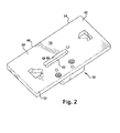
- Fig. 2 provides a top perspective view of an apparatus 30 for inspecting a turbine blade tip shroud 10 according to one embodiment of the present disclosure
- Fig. 3 provides a bottom perspective view of the apparatus 30 shown in Fig. 2
- the apparatus 30 generally includes a frame 32 that is alignable with the turbine blade tip shroud 10.
- "alignable" and (variants thereof) refers to a design that can be independently disposed on a plurality of turbine blade tip shrouds 10 by engaging with the standard or expected topographical profile of the turbine blade tip shroud 10 so that the relative of the position of the frame 32 with the turbine blade tip shroud 10 is consistent and repeatable when aligned thereon.
- the frame 32 may be made from wood, plastic, fiberglass, metal, or any other suitably durable materials capable of maintaining their shape.
- the frame 32 includes a top surface 38 and a bottom surface 40 and may further include one or more viewing holes 42 or other passages to allow visual observation of the tip shroud 10, and/or one or more aligning features such as a first stop 34, and/or a second stop 36 through the frame 32 as will become appreciated herein.
- the frame 32 further comprises at least one z-notch inspection slot 90 that passes through the frame 32 from the top surface 38 to the bottom surface 40.
- the at least one z-notch inspection slot 90 is positioned on the frame 32 to align with one of the z-notches 50 of the turbine blade tip shroud 10 when the frame 32 is aligned on the turbine blade tip shroud 10.
- the z-notch inspection slot 90 comprises an interior edge 92 configured to the acceptable dimensional limits of the z-notch 50 itself.
- the interior edge 92 of the z-notch slot 90 may thereby align with the z-notch 50 of the turbine blade tip shroud 10 to provide a quick visual inspection guide for dimensional conformity, quality or the like.
- the frame 32 may comprise first and second z-notch inspection slots 90 to individually align with first and second z-notches 50 respectively.
- the apparatus 30 further comprises a removable z-notch inspection insert 95 that comprises a cross-sectional profile substantially matching the at least one z-notch inspection slot 90.
- the removable z-notch inspection insert comprises a z-notch guide face 96 that faces the z-notch 90 of the turbine blade tip shroud 10 (and the interior edge 92 of the z-notch inspection slot 90) when the removable z-notch inspection insert 95 is passed through the z-notch inspection slot 90.
- the removable z-notch inspection insert 95 may be passed through the z-notch inspection slot 90 such that its z-notch guide face 96 passes by the interior edge 92 of the z-notch inspection slot and along the surface of the z-notch 50 itself.
- the removable z-notch inspection insert 95 will be blocked from passing through the z-notch inspection slot 90 by catching on the over built z-notch 50. This may lead to the tip shroud 10 being sent for additional work prior to (re)installation in a turbine.
- an under-dimensioned z-notch may be identified by leaving a gap between the z-notch 50 and the z-notch guide face 96 of the z-notch inspection insert 95 when passed through the z-notch inspection slot 90.
- the z-notch inspection slot 90 and the z-notch inspection insert 95 can thereby combine to provide a quick visual and/or physical quality control check on the dimensions of new or modified z-notches 90 of turbine bucket tip shrouds 10.
- the slot 48 may be oriented perpendicular to or parallel to the first surface 46, depending on the particular orientation of the first surface 46 of the first stop 34.
- the frame 32 may include an incremented scale adjacent to the slot 48 and/or second stop 36 to measure the amount of movement of the second stop 36 in the slot 48.
- the second stop 36 may ride in the slot 48 until the second stop 36 either contacts the specific portion of the second side surface 20 or the second stop 36 reaches the end of the slot 48. If the second stop 36 contacts the specific portion of the second side surface 20 before reaching the end of the slot 48, then the tip shroud 10 may be refurbished, for example, by restoring a hardened material to the first and/or second side surfaces 18, 20.
- the tip shroud 10 may require modification before the apparatus 30 may be utilized to verify the dimensional acceptability of the z-notches 50.
- the apparatus 30 may further additionally or alternatively comprise one or more other aligning features for aligning the frame 32 on the turbine blade tip shroud 10.
- the function of the one or more aligning features may be to longitudinally, transversely, and/or radially align the frame 32 with respect to the tip shroud 10.
- the structure for the means may include various combinations of resilient tabs and/or projections that extend from the bottom surface 40 of the frame 32.
- the aligning features for the frame 32 with respect to the tip shroud 10 includes a plurality of resilient tabs 60 that extend away from the frame 32.
- the resilient tabs 60 may be positioned on the frame 32 so that when the frame 32 is placed on the tip shroud 10, the resilient tabs 60 act as bumpers or guides around the leading and/or trailing edges 14, 16 of the tip shroud 10 to position the frame 32 longitudinally and/or transversely with respect to the tip shroud 10.
- the aligning features for the frame 32 with respect to the tip shroud 10 may include first projections 62 and/or second projections 64 on the bottom surface 40 of the frame 32.
- the first projections 62 may be positioned on the frame 32 to rest against or contact the seal rail 22 to position the frame 32 longitudinally with respect to the tip shroud 10.
- the second projections 64 may be positioned on the frame to act as spacers between the bottom surface 40 of the frame 32 and the tip shroud 10. In this manner, the second projections 64 may position the frame 32 radially with respect to the tip shroud 10.
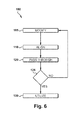
- a method 100 is illustrated for inspecting a turbine blade tip shroud 10.
- the method at least first comprises aligning a frame 32 on the turbine blade tip shroud 10 in step 110.
- the frame comprises at least one z-notch inspection slot 90 that passes through the top surface 38 to the bottom surface 40 and is positioned to align with at least one z-notch 50 of the turbine blade tip shroud 10 while the frame 32 is aligned on the turbine blade tip shroud 10.
- the method 100 may first comprise modifying the z-notch 50 of the turbine blade tip shroud 10 in step 105 prior to aligning the frame 32 with the turbine blade tip shroud 10 in step 110.
- Modifying may comprise any adjustment to the dimensional profile (e.g., size, shape, angle(s), etc.) of the z-notch 50 such as through weld build-up, blending and/or final contouring adjustments including from repair operations, restoration procedures or the like.
- the method may comprise a quality control tollgate in step 125 following the attempting passing of the z-notch inspection insert 95 through the z-notch inspection slot 90 in step 120.
- the turbine blade tip shroud 10 may be sent back to step 105 for further modification and to repeat the overall method 100.
- the turbine blade tip shroud 10 may be utilized for installation in a turbine in step 130.
- the apparatus 30 and methods described herein reduce the time required to consistently inspect z-notches 50 for a turbine blade tip shroud 10 to determine, for example, the dimensional acceptability of the part.
- the embodiments described herein may, in part, reliably identify only those tip shrouds 10 requiring modification, thus assisting in the quality control associated with the inspection and refurbishment of tip shrouds 10.
Landscapes
- Engineering & Computer Science (AREA)
- Mechanical Engineering (AREA)
- General Engineering & Computer Science (AREA)
- Turbine Rotor Nozzle Sealing (AREA)
Abstract
Description
- The present invention generally involves an apparatus and method for inspecting a turbine blade tip shroud. In particular embodiments, the apparatus may facilitate a quality inspection check for turbine blade tip shroud z-notches.
- Turbines are widely used in industrial and commercial operations. A typical commercial steam or gas turbine used to generate electrical power includes alternating stages of stationary vanes and rotating blades. The stationary vanes may be attached to a stationary component such as a casing that surrounds the turbine, and the rotating blades may be attached to a rotor located along an axial centerline of the turbine. A compressed working fluid, such as but not limited to steam, combustion gases, or air, flows through the turbine, and the stationary vanes accelerate and direct the compressed working fluid onto the subsequent stage of rotating blades to impart motion to the rotating blades, thus turning the rotor and performing work.
- Compressed working fluid that leaks around or bypasses the stationary vanes or rotating blades reduces the efficiency of the turbine. To reduce the amount of compressed working fluid that bypasses the rotating blades, the casing may include stationary shroud segments that surround each stage of rotating blades, and each rotating blade may include a tip shroud at an outer radial tip. Each tip shroud may include a seal rail that extends transversely across the tip shroud to form a seal between the rotating tip shroud and the stationary shroud segments. In addition, each tip shroud may include side surfaces that interlock with complementary side surfaces of adjacent tip shrouds to prevent adjacent tip shrouds from overlapping, reduce vibrations in the rotating blades, and enhance the seal between the rotating tip shrouds and the stationary shroud segments.
- Over time, the side surfaces of the tip shrouds may erode or wear, creating gaps between adjacent tip shrouds that allow the rotating blades to twist and/or vibrate and increase the amount of compressed working fluid that bypasses the rotating blades. As a result, hardened materials are typically plated onto the side surfaces and periodically inspected to determine the amount of wear to the hardened materials. If the amount of wear is excessive, the entire rotating blade may need to be replaced. Otherwise, the tip shroud may be refurbished to restore and/or increase the thickness of the hardened materials on the side surfaces.
- Previous efforts have been developed to determine the amount of erosion of the hardened materials. For example, measurements of various chord lengths across the tip shroud may be used to create a detailed coordinate map of the surface of the tip shroud. However, coordinate mapping is time-consuming and produces inconsistent results due to the geometric shape of the tip shroud. As a result, an alternative apparatus and method for inspecting a turbine blade tip shroud would be welcomed in the art.
- Aspects and advantages of the invention are set forth below in the following description, or may be obvious from the description, or may be learned through practice of the invention.
- In one embodiment an apparatus for inspecting a turbine blade tip shroud is disclosed. The apparatus includes a frame comprising a top surface and a bottom surface that is alignable with the turbine blade tip shroud, and, at least one z-notch inspection slot that passes through the frame from the top surface to the bottom surface and is positioned to align with at least one z-notch of the turbine blade tip shroud when the frame is aligned on the turbine blade tip shroud. The apparatus further includes a removable z-notch inspection insert comprising a cross-sectional profile substantially matching the at least one z-notch inspection slot and comprising a z-notch guide face that faces the z-notch of the turbine blade tip shroud when the removable z-notch inspection insert is passed through the z-notch inspection slot.
- In another embodiment, another apparatus for inspecting a turbine blade tip shroud is disclosed. The apparatus includes a frame comprising a top surface and a bottom surface that is alignable with the turbine blade tip shroud, a first z-notch inspection slot that passes through the frame from the top surface to the bottom surface and is positioned to align with a first z-notch of the turbine blade tip shroud when the frame is aligned on the turbine blade tip shroud, and, a first removable z-notch inspection insert comprising a first cross-sectional profile substantially matching the first z-notch inspection slot and comprising a first z-notch guide face that faces the first z-notch of the turbine blade tip shroud when the first removable z-notch inspection insert is passed through the first z-notch inspection slot. The apparatus further includes a second z-notch inspection slot that passes through the frame from the top surface to the bottom surface and is positioned to align with a second z-notch of the turbine blade tip shroud when the frame is aligned on the turbine blade tip shroud, and, a second removable z-notch inspection insert comprising a second cross-sectional profile substantially matching the second z-notch inspection slot and comprising a second z-notch guide face that faces the second z-notch of the turbine blade tip shroud when the second removable z-notch inspection insert is passed through the second z-notch inspection slot.
- In yet another embodiment, a method for inspecting a turbine blade tip shroud is disclosed. The method includes aligning a frame on the turbine blade tip shroud, wherein the frame comprises at least one z-notch inspection slot that passes through the top surface to the bottom surface and is positioned to align with at least one z-notch of the turbine blade tip shroud while the frame is aligned on the turbine blade tip shroud, and passing a removable z-notch inspection insert through the z-notch inspection slot, wherein a z-notch guide face of the z-notch inspection insert will pass by the at least one z-notch of the turbine blade tip shroud if the z-notch does not extend beyond the z-notch inspection slot.
- A full and enabling disclosure of the present invention, including the best mode thereof to one skilled in the art, is set forth more particularly in the remainder of the specification, including reference to the accompanying figures, in which:
-
Fig. 1 is a top plan view of an exemplary turbine blade tip shroud; -
Fig. 2 is a top perspective view of an apparatus for inspecting a turbine blade tip shroud according to one embodiment of the present invention; -
Fig. 3 is a bottom perspective view of the apparatus shown inFig. 2 ; -
Fig. 4 is a top plan view of the apparatus shown inFig. 2 positioned on the turbine blade tip shroud shown inFig. 1 ; -
Fig. 5 is a perspective view of the apparatus shown inFig. 2 positioned on the turbine blade tip shroud shown inFig. 1 ; and -
Fig. 6 is a flow diagram of a method for inspecting a turbine blade tip shroud. - Reference will now be made in detail to present embodiments of the invention, one or more examples of which are illustrated in the accompanying drawings. The detailed description uses numerical and letter designations to refer to features in the drawings. Like or similar designations in the drawings and description have been used to refer to like or similar parts of the invention. As used herein, the terms "first", "second", and "third" may be used interchangeably to distinguish one component from another and are not intended to signify location or importance of the individual components. In addition, the terms "upstream" and "downstream" refer to the relative location of components in a fluid pathway. For example, component A is upstream from component B if a fluid flows from component A to component B. Conversely, component B is downstream from component A if component B receives a fluid flow from component A.
- Each example is provided by way of explanation of the invention, not limitation of the invention. In fact, it will be apparent to those skilled in the art that modifications and variations can be made in the present invention without departing from the scope or spirit thereof. For instance, features illustrated or described as part of one embodiment may be used on another embodiment to yield a still further embodiment. Thus, it is intended that the present invention covers such modifications and variations as come within the scope of the appended claims and their equivalents.
- Various embodiments of the present disclosure include an apparatus and method for inspecting a turbine blade tip shroud. The apparatus generally includes a frame that can be placed over the tip shroud to identify an acceptable or non-acceptable dimension of one or both of the z-notches.
-
Fig. 1 provides a top plan view of an exemplary turbineblade tip shroud 10. Thetip shroud 10 is located at a radial tip of a rotatingblade 12, with the outline of therotating blade 12 beneath thetip shroud 10 shown in phantom inFig. 1 . Thetip shroud 10 generally includes a leadingedge 14 and atrailing edge 16 that correspond to the direction of airflow over the rotatingblade 12. In addition, thetip shroud 10 includes afirst side surface 18 generally opposed to asecond side surface 20, with aseal rail 22 extending across thetip shroud 10 from thefirst side surface 18 to thesecond side surface 20. The first andsecond side surfaces scalloped surfaces 24 and hardenedsurfaces 26 designed to interlock with side surfaces of adjacent tip shrouds. For example, in theexemplary tip shroud 10 shown inFig. 1 , the hardenedsurfaces 26 appear as z-notches 50 in the first andsecond side surfaces - As should be appreciated to those skilled in the art, the z-
notch 50 refers to a z-shaped profile design that reduces or substantially reduces stress in thetip shroud 10. Specifically, the z-notch 50 can help address cracks attributable to low cycle and/or high cycle fatigue. In some embodiments, the z-notch 50 may be present on anew tip shroud 10 from original manufacturing prior to thetip shroud 10 seeing service. In other embodiments, the z-notch 50 may be present after adjusting its dimensional profile through weld build-up, blending and/or contouring from any modification operations (e.g., repair, restoration or the like). -
Fig. 2 provides a top perspective view of anapparatus 30 for inspecting a turbineblade tip shroud 10 according to one embodiment of the present disclosure, andFig. 3 provides a bottom perspective view of theapparatus 30 shown inFig. 2 . Theapparatus 30 generally includes aframe 32 that is alignable with the turbineblade tip shroud 10. As used herein, "alignable" and (variants thereof) refers to a design that can be independently disposed on a plurality of turbineblade tip shrouds 10 by engaging with the standard or expected topographical profile of the turbineblade tip shroud 10 so that the relative of the position of theframe 32 with the turbineblade tip shroud 10 is consistent and repeatable when aligned thereon. Theframe 32 may be made from wood, plastic, fiberglass, metal, or any other suitably durable materials capable of maintaining their shape. Theframe 32 includes atop surface 38 and abottom surface 40 and may further include one or more viewing holes 42 or other passages to allow visual observation of thetip shroud 10, and/or one or more aligning features such as afirst stop 34, and/or asecond stop 36 through theframe 32 as will become appreciated herein. - The
frame 32 further comprises at least one z-notch inspection slot 90 that passes through theframe 32 from thetop surface 38 to thebottom surface 40. As best illustrated inFig. 4 , the at least one z-notch inspection slot 90 is positioned on theframe 32 to align with one of the z-notches 50 of the turbineblade tip shroud 10 when theframe 32 is aligned on the turbineblade tip shroud 10. Specifically, the z-notch inspection slot 90 comprises aninterior edge 92 configured to the acceptable dimensional limits of the z-notch 50 itself. As should be appreciated herein, theinterior edge 92 of the z-notch slot 90 may thereby align with the z-notch 50 of the turbineblade tip shroud 10 to provide a quick visual inspection guide for dimensional conformity, quality or the like. In some embodiments, such as that illustrated inFigs. 2-5 , theframe 32 may comprise first and second z-notch inspection slots 90 to individually align with first and second z-notches 50 respectively. - Referring now to
Fig. 5 , theapparatus 30 further comprises a removable z-notch inspection insert 95 that comprises a cross-sectional profile substantially matching the at least one z-notch inspection slot 90. Specifically, the removable z-notch inspection insert comprises a z-notch guide face 96 that faces the z-notch 90 of the turbine blade tip shroud 10 (and theinterior edge 92 of the z-notch inspection slot 90) when the removable z-notch inspection insert 95 is passed through the z-notch inspection slot 90. In use, the removable z-notch inspection insert 95 may be passed through the z-notch inspection slot 90 such that its z-notch guide face 96 passes by theinterior edge 92 of the z-notch inspection slot and along the surface of the z-notch 50 itself. If the z-notch 50 has excessive material (such as from excessive weld build up, less than required finishing, or other modification operations), the removable z-notch inspection insert 95 will be blocked from passing through the z-notch inspection slot 90 by catching on the over built z-notch 50. This may lead to thetip shroud 10 being sent for additional work prior to (re)installation in a turbine. Conversely, in some embodiments, an under-dimensioned z-notch may be identified by leaving a gap between the z-notch 50 and the z-notch guide face 96 of the z-notch inspection insert 95 when passed through the z-notch inspection slot 90. Thus, the z-notch inspection slot 90 and the z-notch inspection insert 95 can thereby combine to provide a quick visual and/or physical quality control check on the dimensions of new or modified z-notches 90 of turbine bucket tip shrouds 10. - Referring back to
Figs. 2-3 , first and potentially second stops 34, 36 may be positioned on theframe 32 to contact specific portions of the first and second side surfaces 18, 20, respectively to assist in aligning theframe 32 onto the turbineblade tip shroud 10. For example, abolt 44, screw, or other device may be used to releasably attach thefirst stop 34 to a particular location on theframe 32 so that afirst surface 46 of thefirst stop 34 is precisely aligned to contact a specific portion of thefirst side surface 18 of thetip shroud 10. In some embodiments, thefirst stop 34 and thefirst surface 46 may be repositioned and/or re-oriented on theframe 32 so that thesame apparatus 30 may be used to inspect multiple tip shrouds having different geometries. - In some embodiments, a
second stop 36 may similarly be releasably attached to a separate particular location on theframe 32 so that a surface of thesecond stop 36 is precisely aligned to contact a separate specific portion of thesecond side surface 20 of thetip shroud 10. However, in some embodiments, such as that illustrated inFig. 3 , thesecond stop 36 may be in sliding engagement with theframe 32 to contact a specific portion of thesecond side surface 20 of the turbineblade tip shroud 10. For example, as shown inFig. 3 , theframe 32 may include aslot 48 having a predetermined length and orientation with respect to thefirst stop 34. In particular embodiments, theslot 48 may be oriented perpendicular to or parallel to thefirst surface 46, depending on the particular orientation of thefirst surface 46 of thefirst stop 34. Alternately or in addition, theframe 32 may include an incremented scale adjacent to theslot 48 and/orsecond stop 36 to measure the amount of movement of thesecond stop 36 in theslot 48. In this manner, thesecond stop 36 may ride in theslot 48 until thesecond stop 36 either contacts the specific portion of thesecond side surface 20 or thesecond stop 36 reaches the end of theslot 48. If thesecond stop 36 contacts the specific portion of thesecond side surface 20 before reaching the end of theslot 48, then thetip shroud 10 may be refurbished, for example, by restoring a hardened material to the first and/or second side surfaces 18, 20. Alternately, if thesecond stop 36 reaches the end of theslot 48 before contacting the specific portion of thesecond side surface 20, then thetip shroud 10 may require modification before theapparatus 30 may be utilized to verify the dimensional acceptability of the z-notches 50. - As also illustrated in
Fig. 3 , theapparatus 30 may further additionally or alternatively comprise one or more other aligning features for aligning theframe 32 on the turbineblade tip shroud 10. In particular embodiments, the function of the one or more aligning features may be to longitudinally, transversely, and/or radially align theframe 32 with respect to thetip shroud 10. The structure for the means may include various combinations of resilient tabs and/or projections that extend from thebottom surface 40 of theframe 32. In the particular embodiment shown inFig. 3 , for example, the aligning features for theframe 32 with respect to thetip shroud 10 includes a plurality ofresilient tabs 60 that extend away from theframe 32. Theresilient tabs 60 may be positioned on theframe 32 so that when theframe 32 is placed on thetip shroud 10, theresilient tabs 60 act as bumpers or guides around the leading and/or trailingedges tip shroud 10 to position theframe 32 longitudinally and/or transversely with respect to thetip shroud 10. Alternately or in addition, the aligning features for theframe 32 with respect to thetip shroud 10 may includefirst projections 62 and/orsecond projections 64 on thebottom surface 40 of theframe 32. As shown inFig. 3 , thefirst projections 62 may be positioned on theframe 32 to rest against or contact theseal rail 22 to position theframe 32 longitudinally with respect to thetip shroud 10. Similarly, thesecond projections 64 may be positioned on the frame to act as spacers between thebottom surface 40 of theframe 32 and thetip shroud 10. In this manner, thesecond projections 64 may position theframe 32 radially with respect to thetip shroud 10. - Referring now additionally to
Fig. 6 , amethod 100 is illustrated for inspecting a turbineblade tip shroud 10. The method at least first comprises aligning aframe 32 on the turbineblade tip shroud 10 instep 110. As discussed above, the frame comprises at least one z-notch inspection slot 90 that passes through thetop surface 38 to thebottom surface 40 and is positioned to align with at least one z-notch 50 of the turbineblade tip shroud 10 while theframe 32 is aligned on the turbineblade tip shroud 10. - The
method 100 at least further comprises passing a z-notch inspection insert 95 through the z-notch inspection slot 90 instep 120, wherein a z-notch guide face 96 of the z-notch inspection insert 95 will pass by the at least one z-notch 50 of the turbineblade tip shroud 10 if the z-notch 50 does not extend beyond the z-notch inspection slot 90. - In some embodiments, the
method 100 may first comprise modifying the z-notch 50 of the turbineblade tip shroud 10 instep 105 prior to aligning theframe 32 with the turbineblade tip shroud 10 instep 110. Modifying may comprise any adjustment to the dimensional profile (e.g., size, shape, angle(s), etc.) of the z-notch 50 such as through weld build-up, blending and/or final contouring adjustments including from repair operations, restoration procedures or the like. - In even some embodiments, the method may comprise a quality control tollgate in
step 125 following the attempting passing of the z-notch inspection insert 95 through the z-notch inspection slot 90 instep 120. For example, if the z-notch inspection insert 95 cannot pass through the z-notch inspection slot 90 (e.g., due to an overly sized modified or repaired z-notch 50), then the turbineblade tip shroud 10 may be sent back to step 105 for further modification and to repeat theoverall method 100. Likewise, if the z-notch inspection insert 95 can pass through the z-notch inspection slot 90 (e.g., due to and indicating an appropriately sized z-notch 50), the turbineblade tip shroud 10 may be utilized for installation in a turbine instep 130. - One of ordinary skill in the art can readily appreciate that the
apparatus 30 and methods described herein reduce the time required to consistently inspect z-notches 50 for a turbineblade tip shroud 10 to determine, for example, the dimensional acceptability of the part. As a result, the embodiments described herein may, in part, reliably identify only those tip shrouds 10 requiring modification, thus assisting in the quality control associated with the inspection and refurbishment of tip shrouds 10. - This written description uses examples to disclose the invention, including the best mode, and also to enable any person skilled in the art to practice the invention, including making and using any devices or systems and performing any incorporated methods. The patentable scope of the invention is defined by the claims, and may include other examples that occur to those skilled in the art. Such other examples are intended to be within the scope of the claims if they include structural elements that do not differ from the literal language of the claims, or if they include equivalent structural elements with insubstantial differences from the literal languages of the claims.
Claims (14)
- An apparatus for inspecting a turbine blade tip shroud (10), the apparatus comprising:a frame (32) comprising a top surface (38) and a bottom surface (40) that is alignable with the turbine blade tip shroud (10);at least one z-notch inspection slot (90) that passes through the frame (32) from the top surface (38) to the bottom surface (40) and is positioned to align with at least one z-notch (50) of the turbine blade tip shroud (10) when the frame (32) is aligned on the turbine blade tip shroud (10); anda removable z-notch inspection insert (95) comprising a cross-sectional profile substantially matching the at least one z-notch inspection slot (90) and comprising a z-notch guide face (96) that faces the z-notch (50) of the turbine blade tip shroud (10) when the removable z-notch inspection insert (95) is passed through the z-notch inspection slot (90).
- The apparatus of claim 1, further comprising a first stop (34) connected to the bottom surface (40) of the frame (32) to contact a first side surface (18) of the turbine blade tip shroud (10).
- The apparatus of claim 1 or 2, further comprising a second stop (36) connected to the bottom surface (40) of the frame (32) to contact a second side surface (20) of the turbine blade tip shroud (10).
- The apparatus of claim 3, wherein the second stop (36) is in sliding engagement with the frame (32) to contact the second side surface (20).
- The apparatus of any of claims 1 to 4, further comprising a first plurality of projections (62) extending from the bottom surface (40) of the frame (32) to align the frame (32) on the turbine blade tip shroud (10) in a longitudinal direction.
- The apparatus of claim 5, further comprise a second plurality of projections (64) extending from the bottom surface (40) of the frame (32) to align the frame (32) on the turbine blade tip shroud (10) in a transverse direction.
- A method (100) for inspecting a turbine blade tip shroud (10), the method comprising:aligning (110) a frame (32) on the turbine blade tip shroud(10), wherein the frame (32) comprises at least one z-notch inspection slot (90) that passes through a top surface (38) to the bottom surface (40) of the frame and is positioned to align with at least one z-notch (50) of the turbine blade tip shroud (10) while the frame (32) is aligned on the turbine blade tip shroud (90);passing (120) a removable z-notch inspection insert (95) through the z-notch inspection slot (90), wherein a z-notch guide face (96) of the z-notch inspection insert (95) will pass by the at least one z-notch (50) of the turbine blade tip shroud (10) if the z-notch (50) does not extend beyond the z-notch inspection slot (90).
- The method of claim 7, further comprising modifying (105) the at least one z-notch (50) prior to aligning the frame on the turbine blade tip shroud (10).
- The method of claim 8, wherein modifying (105) the at least one z-notch (50) comprises adjusting a dimensional profile of the z-notch (50).
- The method of any of claims 7 to 9, further comprising modifying (105) the at least one z-notch (50) if the removable z-notch inspection insert (95) cannot pass through the at least one z-notch inspection slot (90).
- The method of any of claims 7 to 10, further comprising utilizing (130) the turbine blade tip shroud (10) in a turbine if the removable z-notch inspection insert (95) passes through the at least one z-notch inspection slot (90).
- The method of any of claims 7 to 11, wherein the frame (32) comprises a first stop (34) connected to the bottom surface (40) to contact a first side surface (18) of the turbine blade tip shroud (10), and, a second stop (36) connected to the bottom surface (40) to contact a second side surface (20) of the turbine blade tip shroud (10).
- The method of claim 12, wherein aligning (110) the frame (32) on the turbine blade tip shroud (10) comprises engaging the first stop (34) with the first side surface (18) of the turbine blade tip shroud (10), and, sliding the second stop (36) with respect to the frame (32) until the second stop (36) contacts a second side surface (20) of the turbine blade tip shroud (10).
- The method of any of claims 7 to 13, wherein the turbine blade tip shroud (10) comprises a used turbine blade tip shroud.
Applications Claiming Priority (1)
| Application Number | Priority Date | Filing Date | Title |
|---|---|---|---|
| US14/264,202 US9611753B2 (en) | 2014-04-29 | 2014-04-29 | Apparatus and method for inspecting a turbine blade tip shroud |
Publications (2)
| Publication Number | Publication Date |
|---|---|
| EP2942479A1 true EP2942479A1 (en) | 2015-11-11 |
| EP2942479B1 EP2942479B1 (en) | 2017-03-01 |
Family
ID=53008351
Family Applications (1)
| Application Number | Title | Priority Date | Filing Date |
|---|---|---|---|
| EP15165237.7A Not-in-force EP2942479B1 (en) | 2014-04-29 | 2015-04-27 | Apparatus and method for inspecting a turbine blade tip shroud |
Country Status (2)
| Country | Link |
|---|---|
| US (1) | US9611753B2 (en) |
| EP (1) | EP2942479B1 (en) |
Families Citing this family (3)
| Publication number | Priority date | Publication date | Assignee | Title |
|---|---|---|---|---|
| US10013752B2 (en) * | 2016-11-18 | 2018-07-03 | General Electric Company | Virtual blade inspection |
| US11434777B2 (en) * | 2020-12-18 | 2022-09-06 | General Electric Company | Turbomachine clearance control using magnetically responsive particles |
| FR3149375B1 (en) * | 2023-05-31 | 2025-06-20 | Safran Aircraft Engines | NON-INVASIVE METHOD FOR MONITORING WEAR OF A TURBOMACHINE BLADE |
Citations (3)
| Publication number | Priority date | Publication date | Assignee | Title |
|---|---|---|---|---|
| US4291448A (en) * | 1977-12-12 | 1981-09-29 | Turbine Components Corporation | Method of restoring the shrouds of turbine blades |
| US20070079507A1 (en) * | 2005-10-12 | 2007-04-12 | Kenny Cheng | Blade shroud repair |
| US20140003948A1 (en) * | 2012-07-02 | 2014-01-02 | Thomas Horace Milidantri | Repair Of A Shrouded Blade |
Family Cites Families (17)
| Publication number | Priority date | Publication date | Assignee | Title |
|---|---|---|---|---|
| US2977533A (en) | 1957-11-07 | 1961-03-28 | Sheffield Corp | Gaging device |
| US4333239A (en) * | 1980-06-02 | 1982-06-08 | United Technologies Corporation | Method and apparatus for inspecting shrouds of rotor blades |
| US5133643A (en) | 1989-11-22 | 1992-07-28 | Ortolano Ralph J | Shroud fitting |
| US5162659A (en) | 1991-03-06 | 1992-11-10 | Northwest Airlines, Inc. | Method and apparatus for noncontact inspection of engine blades |
| US6164916A (en) | 1998-11-02 | 2000-12-26 | General Electric Company | Method of applying wear-resistant materials to turbine blades, and turbine blades having wear-resistant materials |
| US6792655B2 (en) | 2001-11-09 | 2004-09-21 | General Electric Company | Apparatus for correcting airfoil twist |
| US6906808B2 (en) | 2002-05-30 | 2005-06-14 | General Electric Company | Methods and apparatus for measuring a surface contour of an object |
| US6701616B2 (en) | 2002-06-28 | 2004-03-09 | General Electric Company | Method of repairing shroud tip overlap on turbine buckets |
| US6842995B2 (en) | 2002-10-09 | 2005-01-18 | General Electric Company | Methods and apparatus for aligning components for inspection |
| US6910278B2 (en) | 2003-01-30 | 2005-06-28 | Lockheed Martin Corporation | Apparatus and method for inspecting and marking repair areas on a blade |
| US7080434B2 (en) | 2003-06-06 | 2006-07-25 | General Electric Company | Fixture having integrated datum locators |
| US7328496B2 (en) | 2003-10-31 | 2008-02-12 | General Electric Company | Apparatus for rebuilding gas turbine engine blades |
| US7024787B2 (en) | 2004-04-01 | 2006-04-11 | United Technologies Corporation | Template for evaluating parts and method of using same |
| JP4831830B2 (en) | 2006-11-01 | 2011-12-07 | 三菱重工業株式会社 | Vibration meter mounting mechanism |
| US7762004B2 (en) | 2007-01-31 | 2010-07-27 | General Electric Company | Inspection tool for measuring bucket Z notch position |
| US8043061B2 (en) | 2007-08-22 | 2011-10-25 | General Electric Company | Turbine bucket tip shroud edge profile |
| US7887295B2 (en) | 2007-11-08 | 2011-02-15 | General Electric Company | Z-Notch shape for a turbine blade |
-
2014
- 2014-04-29 US US14/264,202 patent/US9611753B2/en not_active Expired - Fee Related
-
2015
- 2015-04-27 EP EP15165237.7A patent/EP2942479B1/en not_active Not-in-force
Patent Citations (3)
| Publication number | Priority date | Publication date | Assignee | Title |
|---|---|---|---|---|
| US4291448A (en) * | 1977-12-12 | 1981-09-29 | Turbine Components Corporation | Method of restoring the shrouds of turbine blades |
| US20070079507A1 (en) * | 2005-10-12 | 2007-04-12 | Kenny Cheng | Blade shroud repair |
| US20140003948A1 (en) * | 2012-07-02 | 2014-01-02 | Thomas Horace Milidantri | Repair Of A Shrouded Blade |
Also Published As
| Publication number | Publication date |
|---|---|
| US20150308284A1 (en) | 2015-10-29 |
| EP2942479B1 (en) | 2017-03-01 |
| US9611753B2 (en) | 2017-04-04 |
Similar Documents
| Publication | Publication Date | Title |
|---|---|---|
| US7990547B2 (en) | Apparatus and a method of measuring erosion of an edge of a turbomachine aerofoil | |
| US8695445B2 (en) | Wear-indicating system for use with turbine engines and methods of inspecting same | |
| RU2598906C2 (en) | Method and device for measuring component in turbo machine | |
| EP3182102A1 (en) | System and method for inspecting turbine blades | |
| EP2990660B1 (en) | A wear monitor for a gas turbine engine | |
| JP6080174B2 (en) | Inspection method of impact marks observed in fan casing | |
| EP2942479B1 (en) | Apparatus and method for inspecting a turbine blade tip shroud | |
| US20150075265A1 (en) | Measurement device and method for evaluating turbomachine clearances | |
| US9567860B2 (en) | Fixture for an airfoil shroud and method for modifying an airfoil shroud | |
| EP3176377A1 (en) | Wear indication system and corresponding turbine engine component | |
| US20130180107A1 (en) | Method for refurbishing a turbo-machine component | |
| EP3719256B1 (en) | Aircraft component repair system and process | |
| US9109873B1 (en) | Apparatus and method for inspecting a turbine blade tip shroud | |
| US9803647B2 (en) | Method and system for repairing turbomachine dovetail slots | |
| US10760433B2 (en) | Method for inspecting a rotor blade unit | |
| US20250198735A1 (en) | Method for locating a mark on a turbomachine casing | |
| CN107894457A (en) | Method for the material inspection without destruction | |
| US9764422B2 (en) | Sequencing of multi-pass laser shock peening applications | |
| CN104265681A (en) | Method for changing inherent frequencies of blades | |
| Granovskiy et al. | Effects of blade degradation on turbine performance | |
| Anderson et al. | FCCU PRT Compressor Blade Failure Case Study | |
| US20130224028A1 (en) | Component blending tool assembly | |
| EP3163015A1 (en) | Power nozzle repair with cooling hardware installed | |
| RU2550055C2 (en) | Reconditioning of gas turbine plant including nozzle blades from nickel or cobalt alloys composed of multibank structure | |
| Wasuthalainan et al. | Stress Corrosion Cracking on Steam Turbine Rotor Grooves: Experiences and Countermeasures from EGAT Power Plants |
Legal Events
| Date | Code | Title | Description |
|---|---|---|---|
| PUAI | Public reference made under article 153(3) epc to a published international application that has entered the european phase |
Free format text: ORIGINAL CODE: 0009012 |
|
| AK | Designated contracting states |
Kind code of ref document: A1 Designated state(s): AL AT BE BG CH CY CZ DE DK EE ES FI FR GB GR HR HU IE IS IT LI LT LU LV MC MK MT NL NO PL PT RO RS SE SI SK SM TR |
|
| AX | Request for extension of the european patent |
Extension state: BA ME |
|
| 17P | Request for examination filed |
Effective date: 20160511 |
|
| RBV | Designated contracting states (corrected) |
Designated state(s): AL AT BE BG CH CY CZ DE DK EE ES FI FR GB GR HR HU IE IS IT LI LT LU LV MC MK MT NL NO PL PT RO RS SE SI SK SM TR |
|
| GRAP | Despatch of communication of intention to grant a patent |
Free format text: ORIGINAL CODE: EPIDOSNIGR1 |
|
| RIC1 | Information provided on ipc code assigned before grant |
Ipc: F01D 5/00 20060101AFI20160624BHEP Ipc: F01D 25/00 20060101ALI20160624BHEP Ipc: F01D 21/00 20060101ALI20160624BHEP |
|
| INTG | Intention to grant announced |
Effective date: 20160714 |
|
| GRAJ | Information related to disapproval of communication of intention to grant by the applicant or resumption of examination proceedings by the epo deleted |
Free format text: ORIGINAL CODE: EPIDOSDIGR1 |
|
| GRAP | Despatch of communication of intention to grant a patent |
Free format text: ORIGINAL CODE: EPIDOSNIGR1 |
|
| INTC | Intention to grant announced (deleted) | ||
| INTG | Intention to grant announced |
Effective date: 20161216 |
|
| GRAS | Grant fee paid |
Free format text: ORIGINAL CODE: EPIDOSNIGR3 |
|
| GRAA | (expected) grant |
Free format text: ORIGINAL CODE: 0009210 |
|
| AK | Designated contracting states |
Kind code of ref document: B1 Designated state(s): AL AT BE BG CH CY CZ DE DK EE ES FI FR GB GR HR HU IE IS IT LI LT LU LV MC MK MT NL NO PL PT RO RS SE SI SK SM TR |
|
| REG | Reference to a national code |
Ref country code: GB Ref legal event code: FG4D |
|
| REG | Reference to a national code |
Ref country code: CH Ref legal event code: EP Ref country code: AT Ref legal event code: REF Ref document number: 871596 Country of ref document: AT Kind code of ref document: T Effective date: 20170315 |
|
| REG | Reference to a national code |
Ref country code: IE Ref legal event code: FG4D |
|
| REG | Reference to a national code |
Ref country code: DE Ref legal event code: R096 Ref document number: 602015001606 Country of ref document: DE |
|
| REG | Reference to a national code |
Ref country code: NL Ref legal event code: MP Effective date: 20170301 |
|
| REG | Reference to a national code |
Ref country code: LT Ref legal event code: MG4D |
|
| REG | Reference to a national code |
Ref country code: AT Ref legal event code: MK05 Ref document number: 871596 Country of ref document: AT Kind code of ref document: T Effective date: 20170301 |
|
| PG25 | Lapsed in a contracting state [announced via postgrant information from national office to epo] |
Ref country code: FI Free format text: LAPSE BECAUSE OF FAILURE TO SUBMIT A TRANSLATION OF THE DESCRIPTION OR TO PAY THE FEE WITHIN THE PRESCRIBED TIME-LIMIT Effective date: 20170301 Ref country code: NO Free format text: LAPSE BECAUSE OF FAILURE TO SUBMIT A TRANSLATION OF THE DESCRIPTION OR TO PAY THE FEE WITHIN THE PRESCRIBED TIME-LIMIT Effective date: 20170601 Ref country code: GR Free format text: LAPSE BECAUSE OF FAILURE TO SUBMIT A TRANSLATION OF THE DESCRIPTION OR TO PAY THE FEE WITHIN THE PRESCRIBED TIME-LIMIT Effective date: 20170602 Ref country code: HR Free format text: LAPSE BECAUSE OF FAILURE TO SUBMIT A TRANSLATION OF THE DESCRIPTION OR TO PAY THE FEE WITHIN THE PRESCRIBED TIME-LIMIT Effective date: 20170301 Ref country code: LT Free format text: LAPSE BECAUSE OF FAILURE TO SUBMIT A TRANSLATION OF THE DESCRIPTION OR TO PAY THE FEE WITHIN THE PRESCRIBED TIME-LIMIT Effective date: 20170301 |
|
| PG25 | Lapsed in a contracting state [announced via postgrant information from national office to epo] |
Ref country code: SE Free format text: LAPSE BECAUSE OF FAILURE TO SUBMIT A TRANSLATION OF THE DESCRIPTION OR TO PAY THE FEE WITHIN THE PRESCRIBED TIME-LIMIT Effective date: 20170301 Ref country code: LV Free format text: LAPSE BECAUSE OF FAILURE TO SUBMIT A TRANSLATION OF THE DESCRIPTION OR TO PAY THE FEE WITHIN THE PRESCRIBED TIME-LIMIT Effective date: 20170301 Ref country code: BG Free format text: LAPSE BECAUSE OF FAILURE TO SUBMIT A TRANSLATION OF THE DESCRIPTION OR TO PAY THE FEE WITHIN THE PRESCRIBED TIME-LIMIT Effective date: 20170601 Ref country code: ES Free format text: LAPSE BECAUSE OF FAILURE TO SUBMIT A TRANSLATION OF THE DESCRIPTION OR TO PAY THE FEE WITHIN THE PRESCRIBED TIME-LIMIT Effective date: 20170301 Ref country code: AT Free format text: LAPSE BECAUSE OF FAILURE TO SUBMIT A TRANSLATION OF THE DESCRIPTION OR TO PAY THE FEE WITHIN THE PRESCRIBED TIME-LIMIT Effective date: 20170301 Ref country code: RS Free format text: LAPSE BECAUSE OF FAILURE TO SUBMIT A TRANSLATION OF THE DESCRIPTION OR TO PAY THE FEE WITHIN THE PRESCRIBED TIME-LIMIT Effective date: 20170301 |
|
| PG25 | Lapsed in a contracting state [announced via postgrant information from national office to epo] |
Ref country code: NL Free format text: LAPSE BECAUSE OF FAILURE TO SUBMIT A TRANSLATION OF THE DESCRIPTION OR TO PAY THE FEE WITHIN THE PRESCRIBED TIME-LIMIT Effective date: 20170301 |
|
| PG25 | Lapsed in a contracting state [announced via postgrant information from national office to epo] |
Ref country code: EE Free format text: LAPSE BECAUSE OF FAILURE TO SUBMIT A TRANSLATION OF THE DESCRIPTION OR TO PAY THE FEE WITHIN THE PRESCRIBED TIME-LIMIT Effective date: 20170301 Ref country code: SK Free format text: LAPSE BECAUSE OF FAILURE TO SUBMIT A TRANSLATION OF THE DESCRIPTION OR TO PAY THE FEE WITHIN THE PRESCRIBED TIME-LIMIT Effective date: 20170301 Ref country code: RO Free format text: LAPSE BECAUSE OF FAILURE TO SUBMIT A TRANSLATION OF THE DESCRIPTION OR TO PAY THE FEE WITHIN THE PRESCRIBED TIME-LIMIT Effective date: 20170301 Ref country code: CZ Free format text: LAPSE BECAUSE OF FAILURE TO SUBMIT A TRANSLATION OF THE DESCRIPTION OR TO PAY THE FEE WITHIN THE PRESCRIBED TIME-LIMIT Effective date: 20170301 |
|
| PG25 | Lapsed in a contracting state [announced via postgrant information from national office to epo] |
Ref country code: SM Free format text: LAPSE BECAUSE OF FAILURE TO SUBMIT A TRANSLATION OF THE DESCRIPTION OR TO PAY THE FEE WITHIN THE PRESCRIBED TIME-LIMIT Effective date: 20170301 Ref country code: PT Free format text: LAPSE BECAUSE OF FAILURE TO SUBMIT A TRANSLATION OF THE DESCRIPTION OR TO PAY THE FEE WITHIN THE PRESCRIBED TIME-LIMIT Effective date: 20170703 Ref country code: IS Free format text: LAPSE BECAUSE OF FAILURE TO SUBMIT A TRANSLATION OF THE DESCRIPTION OR TO PAY THE FEE WITHIN THE PRESCRIBED TIME-LIMIT Effective date: 20170701 Ref country code: PL Free format text: LAPSE BECAUSE OF FAILURE TO SUBMIT A TRANSLATION OF THE DESCRIPTION OR TO PAY THE FEE WITHIN THE PRESCRIBED TIME-LIMIT Effective date: 20170301 |
|
| REG | Reference to a national code |
Ref country code: DE Ref legal event code: R097 Ref document number: 602015001606 Country of ref document: DE |
|
| PLBE | No opposition filed within time limit |
Free format text: ORIGINAL CODE: 0009261 |
|
| STAA | Information on the status of an ep patent application or granted ep patent |
Free format text: STATUS: NO OPPOSITION FILED WITHIN TIME LIMIT |
|
| REG | Reference to a national code |
Ref country code: IE Ref legal event code: MM4A |
|
| REG | Reference to a national code |
Ref country code: FR Ref legal event code: ST Effective date: 20171229 |
|
| PG25 | Lapsed in a contracting state [announced via postgrant information from national office to epo] |
Ref country code: MC Free format text: LAPSE BECAUSE OF FAILURE TO SUBMIT A TRANSLATION OF THE DESCRIPTION OR TO PAY THE FEE WITHIN THE PRESCRIBED TIME-LIMIT Effective date: 20170301 Ref country code: DK Free format text: LAPSE BECAUSE OF FAILURE TO SUBMIT A TRANSLATION OF THE DESCRIPTION OR TO PAY THE FEE WITHIN THE PRESCRIBED TIME-LIMIT Effective date: 20170301 Ref country code: FR Free format text: LAPSE BECAUSE OF NON-PAYMENT OF DUE FEES Effective date: 20170502 |
|
| 26N | No opposition filed |
Effective date: 20171204 |
|
| PG25 | Lapsed in a contracting state [announced via postgrant information from national office to epo] |
Ref country code: LU Free format text: LAPSE BECAUSE OF NON-PAYMENT OF DUE FEES Effective date: 20170427 Ref country code: SI Free format text: LAPSE BECAUSE OF FAILURE TO SUBMIT A TRANSLATION OF THE DESCRIPTION OR TO PAY THE FEE WITHIN THE PRESCRIBED TIME-LIMIT Effective date: 20170301 |
|
| REG | Reference to a national code |
Ref country code: BE Ref legal event code: MM Effective date: 20170430 |
|
| PG25 | Lapsed in a contracting state [announced via postgrant information from national office to epo] |
Ref country code: IE Free format text: LAPSE BECAUSE OF NON-PAYMENT OF DUE FEES Effective date: 20170427 |
|
| PG25 | Lapsed in a contracting state [announced via postgrant information from national office to epo] |
Ref country code: BE Free format text: LAPSE BECAUSE OF NON-PAYMENT OF DUE FEES Effective date: 20170430 |
|
| PGFP | Annual fee paid to national office [announced via postgrant information from national office to epo] |
Ref country code: DE Payment date: 20180427 Year of fee payment: 4 |
|
| PG25 | Lapsed in a contracting state [announced via postgrant information from national office to epo] |
Ref country code: MT Free format text: LAPSE BECAUSE OF NON-PAYMENT OF DUE FEES Effective date: 20170427 |
|
| REG | Reference to a national code |
Ref country code: CH Ref legal event code: PL |
|
| PG25 | Lapsed in a contracting state [announced via postgrant information from national office to epo] |
Ref country code: LI Free format text: LAPSE BECAUSE OF NON-PAYMENT OF DUE FEES Effective date: 20180430 Ref country code: CH Free format text: LAPSE BECAUSE OF NON-PAYMENT OF DUE FEES Effective date: 20180430 |
|
| PGFP | Annual fee paid to national office [announced via postgrant information from national office to epo] |
Ref country code: IT Payment date: 20190321 Year of fee payment: 5 |
|
| PG25 | Lapsed in a contracting state [announced via postgrant information from national office to epo] |
Ref country code: HU Free format text: LAPSE BECAUSE OF FAILURE TO SUBMIT A TRANSLATION OF THE DESCRIPTION OR TO PAY THE FEE WITHIN THE PRESCRIBED TIME-LIMIT; INVALID AB INITIO Effective date: 20150427 |
|
| PG25 | Lapsed in a contracting state [announced via postgrant information from national office to epo] |
Ref country code: CY Free format text: LAPSE BECAUSE OF FAILURE TO SUBMIT A TRANSLATION OF THE DESCRIPTION OR TO PAY THE FEE WITHIN THE PRESCRIBED TIME-LIMIT Effective date: 20170301 |
|
| REG | Reference to a national code |
Ref country code: DE Ref legal event code: R119 Ref document number: 602015001606 Country of ref document: DE |
|
| PG25 | Lapsed in a contracting state [announced via postgrant information from national office to epo] |
Ref country code: MK Free format text: LAPSE BECAUSE OF FAILURE TO SUBMIT A TRANSLATION OF THE DESCRIPTION OR TO PAY THE FEE WITHIN THE PRESCRIBED TIME-LIMIT Effective date: 20170301 |
|
| GBPC | Gb: european patent ceased through non-payment of renewal fee |
Effective date: 20190427 |
|
| PG25 | Lapsed in a contracting state [announced via postgrant information from national office to epo] |
Ref country code: GB Free format text: LAPSE BECAUSE OF NON-PAYMENT OF DUE FEES Effective date: 20190427 Ref country code: DE Free format text: LAPSE BECAUSE OF NON-PAYMENT OF DUE FEES Effective date: 20191101 |
|
| PG25 | Lapsed in a contracting state [announced via postgrant information from national office to epo] |
Ref country code: TR Free format text: LAPSE BECAUSE OF FAILURE TO SUBMIT A TRANSLATION OF THE DESCRIPTION OR TO PAY THE FEE WITHIN THE PRESCRIBED TIME-LIMIT Effective date: 20170301 |
|
| PG25 | Lapsed in a contracting state [announced via postgrant information from national office to epo] |
Ref country code: AL Free format text: LAPSE BECAUSE OF FAILURE TO SUBMIT A TRANSLATION OF THE DESCRIPTION OR TO PAY THE FEE WITHIN THE PRESCRIBED TIME-LIMIT Effective date: 20170301 |
|
| PG25 | Lapsed in a contracting state [announced via postgrant information from national office to epo] |
Ref country code: IT Free format text: LAPSE BECAUSE OF NON-PAYMENT OF DUE FEES Effective date: 20200427 |