EP2942421A1 - Method and system for controlling coating in non-line-of-sight locations - Google Patents
Method and system for controlling coating in non-line-of-sight locations Download PDFInfo
- Publication number
- EP2942421A1 EP2942421A1 EP15164546.2A EP15164546A EP2942421A1 EP 2942421 A1 EP2942421 A1 EP 2942421A1 EP 15164546 A EP15164546 A EP 15164546A EP 2942421 A1 EP2942421 A1 EP 2942421A1
- Authority
- EP
- European Patent Office
- Prior art keywords
- coating
- component
- redirecting
- chamber
- desired portion
- Prior art date
- Legal status (The legal status is an assumption and is not a legal conclusion. Google has not performed a legal analysis and makes no representation as to the accuracy of the status listed.)
- Granted
Links
Images



Classifications
-
- C—CHEMISTRY; METALLURGY
- C23—COATING METALLIC MATERIAL; COATING MATERIAL WITH METALLIC MATERIAL; CHEMICAL SURFACE TREATMENT; DIFFUSION TREATMENT OF METALLIC MATERIAL; COATING BY VACUUM EVAPORATION, BY SPUTTERING, BY ION IMPLANTATION OR BY CHEMICAL VAPOUR DEPOSITION, IN GENERAL; INHIBITING CORROSION OF METALLIC MATERIAL OR INCRUSTATION IN GENERAL
- C23C—COATING METALLIC MATERIAL; COATING MATERIAL WITH METALLIC MATERIAL; SURFACE TREATMENT OF METALLIC MATERIAL BY DIFFUSION INTO THE SURFACE, BY CHEMICAL CONVERSION OR SUBSTITUTION; COATING BY VACUUM EVAPORATION, BY SPUTTERING, BY ION IMPLANTATION OR BY CHEMICAL VAPOUR DEPOSITION, IN GENERAL
- C23C16/00—Chemical coating by decomposition of gaseous compounds, without leaving reaction products of surface material in the coating, i.e. chemical vapour deposition [CVD] processes
- C23C16/44—Chemical coating by decomposition of gaseous compounds, without leaving reaction products of surface material in the coating, i.e. chemical vapour deposition [CVD] processes characterised by the method of coating
- C23C16/48—Chemical coating by decomposition of gaseous compounds, without leaving reaction products of surface material in the coating, i.e. chemical vapour deposition [CVD] processes characterised by the method of coating by irradiation, e.g. photolysis, radiolysis, particle radiation
- C23C16/483—Chemical coating by decomposition of gaseous compounds, without leaving reaction products of surface material in the coating, i.e. chemical vapour deposition [CVD] processes characterised by the method of coating by irradiation, e.g. photolysis, radiolysis, particle radiation using coherent light, UV to IR, e.g. lasers
-
- C—CHEMISTRY; METALLURGY
- C23—COATING METALLIC MATERIAL; COATING MATERIAL WITH METALLIC MATERIAL; CHEMICAL SURFACE TREATMENT; DIFFUSION TREATMENT OF METALLIC MATERIAL; COATING BY VACUUM EVAPORATION, BY SPUTTERING, BY ION IMPLANTATION OR BY CHEMICAL VAPOUR DEPOSITION, IN GENERAL; INHIBITING CORROSION OF METALLIC MATERIAL OR INCRUSTATION IN GENERAL
- C23C—COATING METALLIC MATERIAL; COATING MATERIAL WITH METALLIC MATERIAL; SURFACE TREATMENT OF METALLIC MATERIAL BY DIFFUSION INTO THE SURFACE, BY CHEMICAL CONVERSION OR SUBSTITUTION; COATING BY VACUUM EVAPORATION, BY SPUTTERING, BY ION IMPLANTATION OR BY CHEMICAL VAPOUR DEPOSITION, IN GENERAL
- C23C16/00—Chemical coating by decomposition of gaseous compounds, without leaving reaction products of surface material in the coating, i.e. chemical vapour deposition [CVD] processes
- C23C16/04—Coating on selected surface areas, e.g. using masks
- C23C16/045—Coating cavities or hollow spaces, e.g. interior of tubes; Infiltration of porous substrates
-
- C—CHEMISTRY; METALLURGY
- C23—COATING METALLIC MATERIAL; COATING MATERIAL WITH METALLIC MATERIAL; CHEMICAL SURFACE TREATMENT; DIFFUSION TREATMENT OF METALLIC MATERIAL; COATING BY VACUUM EVAPORATION, BY SPUTTERING, BY ION IMPLANTATION OR BY CHEMICAL VAPOUR DEPOSITION, IN GENERAL; INHIBITING CORROSION OF METALLIC MATERIAL OR INCRUSTATION IN GENERAL
- C23C—COATING METALLIC MATERIAL; COATING MATERIAL WITH METALLIC MATERIAL; SURFACE TREATMENT OF METALLIC MATERIAL BY DIFFUSION INTO THE SURFACE, BY CHEMICAL CONVERSION OR SUBSTITUTION; COATING BY VACUUM EVAPORATION, BY SPUTTERING, BY ION IMPLANTATION OR BY CHEMICAL VAPOUR DEPOSITION, IN GENERAL
- C23C16/00—Chemical coating by decomposition of gaseous compounds, without leaving reaction products of surface material in the coating, i.e. chemical vapour deposition [CVD] processes
- C23C16/04—Coating on selected surface areas, e.g. using masks
- C23C16/047—Coating on selected surface areas, e.g. using masks using irradiation by energy or particles
-
- C—CHEMISTRY; METALLURGY
- C23—COATING METALLIC MATERIAL; COATING MATERIAL WITH METALLIC MATERIAL; CHEMICAL SURFACE TREATMENT; DIFFUSION TREATMENT OF METALLIC MATERIAL; COATING BY VACUUM EVAPORATION, BY SPUTTERING, BY ION IMPLANTATION OR BY CHEMICAL VAPOUR DEPOSITION, IN GENERAL; INHIBITING CORROSION OF METALLIC MATERIAL OR INCRUSTATION IN GENERAL
- C23C—COATING METALLIC MATERIAL; COATING MATERIAL WITH METALLIC MATERIAL; SURFACE TREATMENT OF METALLIC MATERIAL BY DIFFUSION INTO THE SURFACE, BY CHEMICAL CONVERSION OR SUBSTITUTION; COATING BY VACUUM EVAPORATION, BY SPUTTERING, BY ION IMPLANTATION OR BY CHEMICAL VAPOUR DEPOSITION, IN GENERAL
- C23C16/00—Chemical coating by decomposition of gaseous compounds, without leaving reaction products of surface material in the coating, i.e. chemical vapour deposition [CVD] processes
- C23C16/22—Chemical coating by decomposition of gaseous compounds, without leaving reaction products of surface material in the coating, i.e. chemical vapour deposition [CVD] processes characterised by the deposition of inorganic material, other than metallic material
- C23C16/30—Deposition of compounds, mixtures or solid solutions, e.g. borides, carbides, nitrides
- C23C16/40—Oxides
- C23C16/405—Oxides of refractory metals or yttrium
-
- C—CHEMISTRY; METALLURGY
- C23—COATING METALLIC MATERIAL; COATING MATERIAL WITH METALLIC MATERIAL; CHEMICAL SURFACE TREATMENT; DIFFUSION TREATMENT OF METALLIC MATERIAL; COATING BY VACUUM EVAPORATION, BY SPUTTERING, BY ION IMPLANTATION OR BY CHEMICAL VAPOUR DEPOSITION, IN GENERAL; INHIBITING CORROSION OF METALLIC MATERIAL OR INCRUSTATION IN GENERAL
- C23C—COATING METALLIC MATERIAL; COATING MATERIAL WITH METALLIC MATERIAL; SURFACE TREATMENT OF METALLIC MATERIAL BY DIFFUSION INTO THE SURFACE, BY CHEMICAL CONVERSION OR SUBSTITUTION; COATING BY VACUUM EVAPORATION, BY SPUTTERING, BY ION IMPLANTATION OR BY CHEMICAL VAPOUR DEPOSITION, IN GENERAL
- C23C16/00—Chemical coating by decomposition of gaseous compounds, without leaving reaction products of surface material in the coating, i.e. chemical vapour deposition [CVD] processes
- C23C16/44—Chemical coating by decomposition of gaseous compounds, without leaving reaction products of surface material in the coating, i.e. chemical vapour deposition [CVD] processes characterised by the method of coating
- C23C16/455—Chemical coating by decomposition of gaseous compounds, without leaving reaction products of surface material in the coating, i.e. chemical vapour deposition [CVD] processes characterised by the method of coating characterised by the method used for introducing gases into reaction chamber or for modifying gas flows in reaction chamber
- C23C16/45517—Confinement of gases to vicinity of substrate
-
- C—CHEMISTRY; METALLURGY
- C23—COATING METALLIC MATERIAL; COATING MATERIAL WITH METALLIC MATERIAL; CHEMICAL SURFACE TREATMENT; DIFFUSION TREATMENT OF METALLIC MATERIAL; COATING BY VACUUM EVAPORATION, BY SPUTTERING, BY ION IMPLANTATION OR BY CHEMICAL VAPOUR DEPOSITION, IN GENERAL; INHIBITING CORROSION OF METALLIC MATERIAL OR INCRUSTATION IN GENERAL
- C23C—COATING METALLIC MATERIAL; COATING MATERIAL WITH METALLIC MATERIAL; SURFACE TREATMENT OF METALLIC MATERIAL BY DIFFUSION INTO THE SURFACE, BY CHEMICAL CONVERSION OR SUBSTITUTION; COATING BY VACUUM EVAPORATION, BY SPUTTERING, BY ION IMPLANTATION OR BY CHEMICAL VAPOUR DEPOSITION, IN GENERAL
- C23C16/00—Chemical coating by decomposition of gaseous compounds, without leaving reaction products of surface material in the coating, i.e. chemical vapour deposition [CVD] processes
- C23C16/44—Chemical coating by decomposition of gaseous compounds, without leaving reaction products of surface material in the coating, i.e. chemical vapour deposition [CVD] processes characterised by the method of coating
- C23C16/455—Chemical coating by decomposition of gaseous compounds, without leaving reaction products of surface material in the coating, i.e. chemical vapour deposition [CVD] processes characterised by the method of coating characterised by the method used for introducing gases into reaction chamber or for modifying gas flows in reaction chamber
- C23C16/45582—Expansion of gas before it reaches the substrate
-
- C—CHEMISTRY; METALLURGY
- C23—COATING METALLIC MATERIAL; COATING MATERIAL WITH METALLIC MATERIAL; CHEMICAL SURFACE TREATMENT; DIFFUSION TREATMENT OF METALLIC MATERIAL; COATING BY VACUUM EVAPORATION, BY SPUTTERING, BY ION IMPLANTATION OR BY CHEMICAL VAPOUR DEPOSITION, IN GENERAL; INHIBITING CORROSION OF METALLIC MATERIAL OR INCRUSTATION IN GENERAL
- C23C—COATING METALLIC MATERIAL; COATING MATERIAL WITH METALLIC MATERIAL; SURFACE TREATMENT OF METALLIC MATERIAL BY DIFFUSION INTO THE SURFACE, BY CHEMICAL CONVERSION OR SUBSTITUTION; COATING BY VACUUM EVAPORATION, BY SPUTTERING, BY ION IMPLANTATION OR BY CHEMICAL VAPOUR DEPOSITION, IN GENERAL
- C23C16/00—Chemical coating by decomposition of gaseous compounds, without leaving reaction products of surface material in the coating, i.e. chemical vapour deposition [CVD] processes
- C23C16/44—Chemical coating by decomposition of gaseous compounds, without leaving reaction products of surface material in the coating, i.e. chemical vapour deposition [CVD] processes characterised by the method of coating
- C23C16/48—Chemical coating by decomposition of gaseous compounds, without leaving reaction products of surface material in the coating, i.e. chemical vapour deposition [CVD] processes characterised by the method of coating by irradiation, e.g. photolysis, radiolysis, particle radiation
- C23C16/481—Chemical coating by decomposition of gaseous compounds, without leaving reaction products of surface material in the coating, i.e. chemical vapour deposition [CVD] processes characterised by the method of coating by irradiation, e.g. photolysis, radiolysis, particle radiation by radiant heating of the substrate
-
- F—MECHANICAL ENGINEERING; LIGHTING; HEATING; WEAPONS; BLASTING
- F01—MACHINES OR ENGINES IN GENERAL; ENGINE PLANTS IN GENERAL; STEAM ENGINES
- F01D—NON-POSITIVE DISPLACEMENT MACHINES OR ENGINES, e.g. STEAM TURBINES
- F01D5/00—Blades; Blade-carrying members; Heating, heat-insulating, cooling or antivibration means on the blades or the members
- F01D5/12—Blades
- F01D5/28—Selecting particular materials; Particular measures relating thereto; Measures against erosion or corrosion
- F01D5/284—Selection of ceramic materials
-
- F—MECHANICAL ENGINEERING; LIGHTING; HEATING; WEAPONS; BLASTING
- F01—MACHINES OR ENGINES IN GENERAL; ENGINE PLANTS IN GENERAL; STEAM ENGINES
- F01D—NON-POSITIVE DISPLACEMENT MACHINES OR ENGINES, e.g. STEAM TURBINES
- F01D5/00—Blades; Blade-carrying members; Heating, heat-insulating, cooling or antivibration means on the blades or the members
- F01D5/12—Blades
- F01D5/28—Selecting particular materials; Particular measures relating thereto; Measures against erosion or corrosion
- F01D5/288—Protective coatings for blades
-
- F—MECHANICAL ENGINEERING; LIGHTING; HEATING; WEAPONS; BLASTING
- F05—INDEXING SCHEMES RELATING TO ENGINES OR PUMPS IN VARIOUS SUBCLASSES OF CLASSES F01-F04
- F05D—INDEXING SCHEME FOR ASPECTS RELATING TO NON-POSITIVE-DISPLACEMENT MACHINES OR ENGINES, GAS-TURBINES OR JET-PROPULSION PLANTS
- F05D2230/00—Manufacture
- F05D2230/10—Manufacture by removing material
- F05D2230/13—Manufacture by removing material using lasers
Definitions
- the present disclosure is directed to a method and system for controlling the formation of a coating on non-line-of-sight locations on turbine engine components such as turbine airfoils.
- the components of the turbine stages should be able to withstand the thermal and oxidation conditions of the high temperature combustion gas during the course of operation.
- surfaces exposed to hot combustion gases are coated with metallic bond coats that provide oxidation and corrosion resistance, and with thermal barrier coatings (TBC) that provide thermal protection.
- Thermal protection is provided by a low thermal conductivity ceramic top coat that decreases the heat flux into the part.
- Hot section part coatings are often multilayer systems that include a thermally insulating porous ceramic overlay deposited on top of various interface layers that provide thermal and environmental protection and bonding to the metal alloy substrate. The total thickness of all coatings varies between approximately 0.005 to 0.020 inches (0.013-0.051 cm) thick.
- TBC layers are typically made up of yttria partially-stabilized zirconia (YSPZ).
- YSPZ yttria partially-stabilized zirconia
- the TBC has a very high melting temperature and low thermal conductivity and is resistant to oxidation and corrosion and has good phase stability.
- Modern TBCs can provide an extra 300°F (149°C) reduction in metal temperature; however, the TBC allows oxygen to freely diffuse through it, therefore, it does not provide any addition EBC benefit versus oxidation.
- the thermal expansion coefficient of the TBC should be similar to that of the alloy; otherwise the mismatch can induce cracking and spallation during thermal cyclic operation.
- EBC environmental barrier coatings
- metallic aluminide or platinum aluminide approximately 0.002 - 0.004 inches (0.005-0.010 cm) thick
- Chromide coatings provide good protection for high Cr base alloys against corrosion due to molten salts, pollutants, and sands in the environment.
- Aluminide bond coatings are a class of EBCs for nickel-based superalloys that are used in multilayered coating systems underneath ceramic overlays.
- TBCs are deposited on top of an alumina forming metallic bond coat that acts as an interface between the TBC and the superalloy substrate.
- the bond coat is used both for protection against oxidation, and to improve adherence to the metal substrate.
- the ceramic overlay TBC provides thermal protection while the interface bond EBC provides environmental protection to improve resistance against oxidation and corrosion.
- the aluminum improves the bond of the ceramic top coat to the metallic alloy substrate.
- the aluminide coating also acts as a reservoir of aluminum to reduce diffusion of Al to the surface. They typically are 0.002 inches (0.005 cm) thick bond coat with an inter-diffusion layer approximately 0.002 inches (0.005 cm) thick.
- the diffusion layer is non-load carrying.
- FIG. 1 there is shown a vane cluster 10 having a plurality of airfoils 12.
- Each airfoil 12 may interfere with the application of a coating to an adjacent airfoil(s) 12, in the regions 14. This is because the vane cluster geometry provides a mask which affects coating distribution on the hidden faces of the airfoils 12 in the regions 14, thereby reducing the amount of coating which is applied to those areas. Such non-uniformity may be further exacerbated by the absence of interference to the application of the coating on the surfaces at each end of the vane cluster. This is true even when so-called non-line of sight coating application methods, such as electron beam physical vapor deposition (EB-PVD), are used.
- EB-PVD electron beam physical vapor deposition
- the hidden areas may not receive adequate coating thickness due to the exposed areas on either end of the vane cluster reaching the coating thickness limit, thereby creating non-uniformity of coating profiles from vane to vane.
- the varying coating distribution between the two airfoils creates a situation of mismatched thermal gradients and thermal growth.
- Additive layer manufacturing (ALM) devices such as direct metal laser sintering (DMLS), selective laser melting (SLM), laser beam melting (LBM) and electron beam melting (EBM), provide for the fabrication of complex metal, alloy, polymer, ceramic and composite structures by the freeform construction of the material, layer by layer.
- DMLS direct metal laser sintering
- SLM selective laser melting
- LBM laser beam melting
- EBM electron beam melting
- the principle behind additive manufacturing processes involves the selective melting of atomized precursor powder beds by a directed energy source, producing the lithographic build up of material. The melting of the powder occurs in a small localized region of the energy beam, producing small volumes of melting, called melt pools, followed by rapid solidification, allowing for very precise control of the solidification process in the layer-by-layer fabrication of the material.
- melt pools small volumes of melting
- melt pools small volumes of melting
- rapid solidification allowing for very precise control of the solidification process in the layer-by-layer fabrication of the material.
- CAD computer aided design
- Laser Chemical Vapor Deposition is an additive manufacturing process that a solid deposit is formed from gaseous reactants which uses a laser to heat the substrate and enhance the surface reactions in a desired location.
- the LCVD pyrolytic process utilizes a non-reacting gas field to transport a target material onto a high temperature substrate.
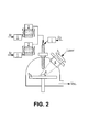
- a laser CVD apparatus which includes: mass flow controller 1, precursor evaporator 2, optical lens 3, quartz window 4, substrate holder 5, and substrate 6.
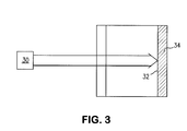
- LCVD utilizes a laser 30 within the gas field to locally enhance surface reactions for the directed deposition of coating material along the target surface 32. This allows for controlled growth of the target material onto the substrate 32.
- LCVD has been utilized since the early 1970s to create small feature objects such as carbon nanotubes.
- the deposited material is much more pure than a powder deposition dependent process and does not suffer from deposit degradation as similar additive processes such as delamination or high porosity.
- Another unique deposit characteristic in LCVD is to make conformal deposits 40 on concave or convex substrates 42 results in conformal layers 44 such as shown in FIG. 4A that conform to non-planar substrates 42.
- powderbed/powder deposition techniques as shown in FIG. 4B form planar layers 46 on the non-planar substrate 48.
- a method for coating a turbine engine component which method broadly comprises the steps of: placing the component into a chamber; injecting a non-reactive carrier gas containing a coating material into the chamber; and forming a coating on a desired portion of the component by locally heating the desired portion of the component by redirecting a directed energy beam onto the desired portion of the component.
- the redirecting step may comprise articulating a redirecting surface so that the directed energy beam is directed onto the desired portion of the component.
- the method may further comprise causing the redirecting surface to raster across the desired portion.
- the articulating step may comprise articulating a mirror.
- the injecting step may comprise injecting a gas containing materials for forming one of a bond coating, a thermal barrier coating, an environmental coating, and a ceramic metallic coating.
- the method may further comprise maintaining the non-reactive carrier gas containing the coating material at a temperature lower than the deposition temperature of the coating material.
- the component placing step may comprise placing a turbine vane pack having a plurality of airfoils in the chamber.
- the coating forming step may comprise forming a coating on hidden portions of the airfoils.
- the method may further comprise providing a laser for generating a laser beam; and the redirecting step may comprise redirecting the laser beam onto the desired portion of the component.
- a system for coating a turbine engine component which system broadly comprises: a chamber for holding the component to be coated; a non-reactive carrier gas containing a coating material to be injected into the chamber; a directed energy beam source for generating an energy beam; and a redirecting surface for redirecting the energy beam onto a desired portion of the component.
- the chamber may have an inlet for the non-reactive carrier gas.
- the chamber may have a transparent layer through which the energy beam is directed to the redirecting surface.
- the coating material may comprise one of a bond coating material, a thermal barrier coating material, an environmental coating material, and a ceramic environmental coating material.
- the directed energy beam source may comprise a laser for generating a laser beam.
- the redirecting surface may comprise an articulated redirecting surface for redirecting the energy beam so that a desired portion of the component is locally heated.
- the articulated redirecting surface may be attached to a wall of the chamber.
- the component may comprise a turbine vane pack having a platform and a plurality of airfoils having hidden portions to be coated.
- the redirecting surface may comprise a mirror.
- the present disclosure relates to a LCVD method and system that distributes a coating to hidden portions of a gas turbine engine component, such as an airfoil vane pack, a turbine blade, and other hot section components that are difficult to coat.
- a gas turbine engine component such as an airfoil vane pack, a turbine blade, and other hot section components that are difficult to coat.
- the method and system described herein are useful for coating complex shaped parts because it allows one to locally control the coating thickness distribution to be either more uniform or thicker in areas where it is needed and thinner in other areas.
- typical double vane packs have a portion 14 that does not lend itself to being coated using traditional coating processes of direct plasma spray or electron-beam vapor deposition.
- FIG. 5 illustrates a turbine vane pack 50 to be coated. While the present disclosure will be presented in the context of forming a coating on hidden portions of a turbine vane pack, as discussed above, the method and system described herein can be used to coat other gas turbine engine components such as turbine blades, turbine airfoils, and other hot section components that are difficult to coat.
- the turbine vane pack 50 includes a platform 52, a plurality of airfoils 54, and a fillet region 56.
- the turbine vane pack 50 and its elements may be formed from any suitable material known in the art, such as a metal, a metal alloy, a monolithic ceramic material, or a composite material (e.g. a ceramic matrix composite material).
- the turbine vane pack 50 may be formed from one of these materials or a combination of these materials.
- FIG. 6 illustrates a system 60 in accordance with the present disclosure for applying a coating to hidden portions 61 and 62 of the component being coated such as the airfoils 54 of the turbine vane pack 50.
- the system 60 includes a chamber 64 having a transparent layer 66.
- the turbine vane pack 50 to be coated is placed within the chamber 64.
- the system 60 further includes a directed energy source 68, such as a laser.
- the directed energy source 68 applies an energy beam 70 through the transparent layer 66.
- Mounted within the chamber 64 is an articulated redirecting surface 72 such as a mirror.
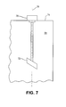
- the redirecting surface 72 may be used to reflect the energy beam 70 or cause refraction of the energy beam 70. As shown in FIG. 7 , the redirecting surface 72 may be mounted to a wall 74 of the chamber 64.
- a device 76 for rotating the articulated redirecting surface 72 about an axis 78 may also be provided. Still further, the redirecting surface 72 may be adapted to rotate and otherwise move about multiple axes so that the desired coating may be achieved. For example, the redirecting surface 72 may be mounted so that it can move in two axes at an angle to the axis 78.
- the system 60 further includes an inlet 80 for injecting into the chamber 64 a non-reacting material carrier gas containing a material or materials to be deposited onto the hidden portions 61 and 62.
- the gas is injected into the chamber 64 so that the turbine vane pack 50 is immersed in a non-reacting gas cloud at a temperature subsequently lower than the deposition temperature of the constituent material for forming the desired coating on the hidden portions 61 and 62.
- an energy beam 70 from the directed energy source 68 such as a laser beam from a laser
- the laser strike causes a very high and very local temperature strike on the surface of the one airfoil 54 causing the coating material in the chamber 64 to debond from the carrier gas and deposit on the surface of the airfoil 54.
- the directed energy source locally applies a coating to the airfoil 54 through local heating of the airfoil surface.
- the redirecting surface 72 is articulated to cause the energy beam 70 to raster across the area where the coating is desired. In this way, the hidden areas 61 and 62 may have a coating applied to them.
- the coating material which may be deposited onto the desired surfaces of the airfoil 54 may include a bond coat, a thermal barrier coating, an environmental coating, such as a metallic environmental coating, or a ceramic environmental barrier coating.
- Coatings which may be formed using the process described herein include yttria partially-stabilized zirconia, aluminides, platinum aluminides, chromides, barium strontium aluminosilicates, yttrium silicates, silicon nitrides, molybdenum, tantalum, titanium, titanium nitrides, niobium oxides, tungsten, and tungsten carbides.
- the method described herein may use vaporized zirconium dipivaloylmethanate, Zr(dpm), and yttrium dipivaloylmethanate Y(dpm) as the precursor gas(es).
- the vaporization temperatures of these are 573°K and 443°K, respectively.
- the precursors may be delivered by a carrier gas, such as Argon, Ar, with oxygen O 2 , introduced from a separate nozzle in order to react with Zr and produce zirconia, ZrO 2 , on a substrate.
- the coatings formed by the method and system described herein may have a controlled columnar microstructure through sintering direction. If desired, relative to a concave or convex surface, one can use the directed energy beam angle to produce a column that is not necessarily perpendicular to the surface.
- the method and system described herein have a number of benefits. These may include a dramatic increase for part durability in shadowed locations; an increase part life by 2 to 5 times; an increase in thrust specific fuel consumption (TSFC) through the turbine inlet temperature (T4) increases due to part capability increases; and better coating performance through the entirety of the part through better conformal application of the coating microstructure.
- TSFC thrust specific fuel consumption
- T4 turbine inlet temperature
- the method and system described herein allow batch coating of larger amounts of turbine engine components, such as turbine blades, in a more uniform manner without necessarily needing a tertiary motion system.
Landscapes
- Chemical & Material Sciences (AREA)
- Engineering & Computer Science (AREA)
- Mechanical Engineering (AREA)
- Materials Engineering (AREA)
- Metallurgy (AREA)
- General Chemical & Material Sciences (AREA)
- Chemical Kinetics & Catalysis (AREA)
- Organic Chemistry (AREA)
- Health & Medical Sciences (AREA)
- Toxicology (AREA)
- General Engineering & Computer Science (AREA)
- Ceramic Engineering (AREA)
- Physics & Mathematics (AREA)
- Optics & Photonics (AREA)
- Inorganic Chemistry (AREA)
- Turbine Rotor Nozzle Sealing (AREA)
Abstract
Description
- The present disclosure is directed to a method and system for controlling the formation of a coating on non-line-of-sight locations on turbine engine components such as turbine airfoils.
- In the pursuit of ever higher efficiencies, gas turbine engine manufacturers have relied on higher and higher turbine inlet temperatures to provide boosts to overall engine performance. In typical modern engine applications, the gas path temperatures within the turbine may exceed the melting point of the component constituent materials. Due to this possibility, dedicated cooling air is extracted from the compressor and used to cool the gas path components, including rotating blades and stator vanes, in the turbine. As a result, significant cycle penalties may be incurred.
- The components of the turbine stages (e.g. vanes and blades) should be able to withstand the thermal and oxidation conditions of the high temperature combustion gas during the course of operation. To protect turbine engine components from the extreme conditions, surfaces exposed to hot combustion gases are coated with metallic bond coats that provide oxidation and corrosion resistance, and with thermal barrier coatings (TBC) that provide thermal protection. Thermal protection is provided by a low thermal conductivity ceramic top coat that decreases the heat flux into the part. Hot section part coatings are often multilayer systems that include a thermally insulating porous ceramic overlay deposited on top of various interface layers that provide thermal and environmental protection and bonding to the metal alloy substrate. The total thickness of all coatings varies between approximately 0.005 to 0.020 inches (0.013-0.051 cm) thick. TBC layers are typically made up of yttria partially-stabilized zirconia (YSPZ). The TBC has a very high melting temperature and low thermal conductivity and is resistant to oxidation and corrosion and has good phase stability. Modern TBCs can provide an extra 300°F (149°C) reduction in metal temperature; however, the TBC allows oxygen to freely diffuse through it, therefore, it does not provide any addition EBC benefit versus oxidation. In addition, the thermal expansion coefficient of the TBC should be similar to that of the alloy; otherwise the mismatch can induce cracking and spallation during thermal cyclic operation.
- In order to protect the turbine components constructed from nickel-based superalloy, environmental barrier coatings (EBC), usually metallic aluminide or platinum aluminide approximately 0.002 - 0.004 inches (0.005-0.010 cm) thick, provide oxidation and corrosion protection. The most common is NiCoCrAlY, containing 12% aluminum. Chromide coatings provide good protection for high Cr base alloys against corrosion due to molten salts, pollutants, and sands in the environment.
- Aluminide bond coatings, or diffusion coatings, are a class of EBCs for nickel-based superalloys that are used in multilayered coating systems underneath ceramic overlays. TBCs are deposited on top of an alumina forming metallic bond coat that acts as an interface between the TBC and the superalloy substrate. The bond coat is used both for protection against oxidation, and to improve adherence to the metal substrate. The ceramic overlay TBC provides thermal protection while the interface bond EBC provides environmental protection to improve resistance against oxidation and corrosion. The aluminum improves the bond of the ceramic top coat to the metallic alloy substrate. The aluminide coating also acts as a reservoir of aluminum to reduce diffusion of Al to the surface. They typically are 0.002 inches (0.005 cm) thick bond coat with an inter-diffusion layer approximately 0.002 inches (0.005 cm) thick. The diffusion layer is non-load carrying.
- Referring now to
FIG. 1 , there is shown avane cluster 10 having a plurality ofairfoils 12. Eachairfoil 12 may interfere with the application of a coating to an adjacent airfoil(s) 12, in theregions 14. This is because the vane cluster geometry provides a mask which affects coating distribution on the hidden faces of theairfoils 12 in theregions 14, thereby reducing the amount of coating which is applied to those areas. Such non-uniformity may be further exacerbated by the absence of interference to the application of the coating on the surfaces at each end of the vane cluster. This is true even when so-called non-line of sight coating application methods, such as electron beam physical vapor deposition (EB-PVD), are used. The hidden areas may not receive adequate coating thickness due to the exposed areas on either end of the vane cluster reaching the coating thickness limit, thereby creating non-uniformity of coating profiles from vane to vane. The varying coating distribution between the two airfoils creates a situation of mismatched thermal gradients and thermal growth. - Additive layer manufacturing (ALM) devices, such as direct metal laser sintering (DMLS), selective laser melting (SLM), laser beam melting (LBM) and electron beam melting (EBM), provide for the fabrication of complex metal, alloy, polymer, ceramic and composite structures by the freeform construction of the material, layer by layer. The principle behind additive manufacturing processes involves the selective melting of atomized precursor powder beds by a directed energy source, producing the lithographic build up of material. The melting of the powder occurs in a small localized region of the energy beam, producing small volumes of melting, called melt pools, followed by rapid solidification, allowing for very precise control of the solidification process in the layer-by-layer fabrication of the material. These devices are directed by three-dimensional geometry solid models developed in computer aided design (CAD) software systems. This allows for the fabrication of very complex and multifunctional components from a wide variety of precursor materials.
- Laser Chemical Vapor Deposition (LCVD) is an additive manufacturing process that a solid deposit is formed from gaseous reactants which uses a laser to heat the substrate and enhance the surface reactions in a desired location. Building off of the chemical deposition process, the LCVD pyrolytic process utilizes a non-reacting gas field to transport a target material onto a high temperature substrate. Referring now to
FIG. 2 , there is shown a laser CVD apparatus which includes:mass flow controller 1,precursor evaporator 2, optical lens 3, quartz window 4, substrate holder 5, and substrate 6. Referring now toFIG. 3 , LCVD utilizes alaser 30 within the gas field to locally enhance surface reactions for the directed deposition of coating material along thetarget surface 32. This allows for controlled growth of the target material onto thesubstrate 32. The LCVD process has been utilized since the early 1970s to create small feature objects such as carbon nanotubes. Relative to powder bed systems such as DMLS or electron beam melting machines, LCVD utilizes a maskless process that does not need oscillatory material layering. Further, as a consequence of the gaseous material transport, the deposited material is much more pure than a powder deposition dependent process and does not suffer from deposit degradation as similar additive processes such as delamination or high porosity. Another unique deposit characteristic in LCVD is to makeconformal deposits 40 on concave orconvex substrates 42 results inconformal layers 44 such as shown inFIG. 4A that conform to non-planarsubstrates 42. In comparison, powderbed/powder deposition techniques as shown inFIG. 4B formplanar layers 46 on thenon-planar substrate 48. - In accordance with the present disclosure, there is provided a method for coating a turbine engine component, which method broadly comprises the steps of: placing the component into a chamber; injecting a non-reactive carrier gas containing a coating material into the chamber; and forming a coating on a desired portion of the component by locally heating the desired portion of the component by redirecting a directed energy beam onto the desired portion of the component.
- In another and alternative embodiment, the redirecting step may comprise articulating a redirecting surface so that the directed energy beam is directed onto the desired portion of the component.
- In another and alternative embodiment, the method may further comprise causing the redirecting surface to raster across the desired portion.
- In another and alternative embodiment, the articulating step may comprise articulating a mirror.
- In another and alternative embodiment, the injecting step may comprise injecting a gas containing materials for forming one of a bond coating, a thermal barrier coating, an environmental coating, and a ceramic metallic coating.
- In another and alternative embodiment, the method may further comprise maintaining the non-reactive carrier gas containing the coating material at a temperature lower than the deposition temperature of the coating material.
- In another and alternative embodiment, the component placing step may comprise placing a turbine vane pack having a plurality of airfoils in the chamber.
- In another and alternative embodiment, the coating forming step may comprise forming a coating on hidden portions of the airfoils.
- In another and alternative embodiment, the method may further comprise providing a laser for generating a laser beam; and the redirecting step may comprise redirecting the laser beam onto the desired portion of the component.
- Further in accordance with the present disclosure, there is provide a system for coating a turbine engine component, which system broadly comprises: a chamber for holding the component to be coated; a non-reactive carrier gas containing a coating material to be injected into the chamber; a directed energy beam source for generating an energy beam; and a redirecting surface for redirecting the energy beam onto a desired portion of the component.
- In another and alternative embodiment, the chamber may have an inlet for the non-reactive carrier gas.
- In another and alternative embodiment, the chamber may have a transparent layer through which the energy beam is directed to the redirecting surface.
- In another and alternative embodiment, the coating material may comprise one of a bond coating material, a thermal barrier coating material, an environmental coating material, and a ceramic environmental coating material.
- In another and alternative embodiment, the directed energy beam source may comprise a laser for generating a laser beam.
- In another and alternative embodiment, the redirecting surface may comprise an articulated redirecting surface for redirecting the energy beam so that a desired portion of the component is locally heated.
- In another and alternative embodiment, the articulated redirecting surface may be attached to a wall of the chamber.
- In another and alternative embodiment, the component may comprise a turbine vane pack having a platform and a plurality of airfoils having hidden portions to be coated.
- In another and alternative embodiment, the redirecting surface may comprise a mirror.
- Other details of the method and system for controlling coating in non-line of sight locations are set forth, by way of example only, in the following detailed description and the accompanying drawings, wherein like reference numerals depict like elements.
-
-
FIG. 1 is a schematic representation of a portion of a vane cluster showing shadowed regions; -
FIG. 2 is a schematic representation of a deposition process showing gasification of pure silicon; -
FIG. 3 is a schematic representation of a LCVD deposition process; -
FIGS. 4A and 4B illustration between the conformal layers formed using an LCVD deposition process and the planar layers formed using a powderbed/powder deposition process; -
FIG. 5 is a perspective view of a turbine vane pack; -
FIG. 6 is a schematic representation of a system for applying a protective coating to hidden areas of the turbine vane pack ofFIG. 5 ; and -
FIG. 7 illustrates a schematic representation of a portion of the system ofFIG. 6 . - As described herein, by way of example only, the present disclosure relates to a LCVD method and system that distributes a coating to hidden portions of a gas turbine engine component, such as an airfoil vane pack, a turbine blade, and other hot section components that are difficult to coat. The method and system described herein are useful for coating complex shaped parts because it allows one to locally control the coating thickness distribution to be either more uniform or thicker in areas where it is needed and thinner in other areas.
- As shown in
FIG. 1 , typical double vane packs have aportion 14 that does not lend itself to being coated using traditional coating processes of direct plasma spray or electron-beam vapor deposition. -
FIG. 5 illustrates aturbine vane pack 50 to be coated. While the present disclosure will be presented in the context of forming a coating on hidden portions of a turbine vane pack, as discussed above, the method and system described herein can be used to coat other gas turbine engine components such as turbine blades, turbine airfoils, and other hot section components that are difficult to coat. Theturbine vane pack 50 includes aplatform 52, a plurality ofairfoils 54, and afillet region 56. Theturbine vane pack 50 and its elements may be formed from any suitable material known in the art, such as a metal, a metal alloy, a monolithic ceramic material, or a composite material (e.g. a ceramic matrix composite material). Theturbine vane pack 50 may be formed from one of these materials or a combination of these materials. -
FIG. 6 illustrates asystem 60 in accordance with the present disclosure for applying a coating to hiddenportions airfoils 54 of theturbine vane pack 50. Thesystem 60 includes achamber 64 having atransparent layer 66. Theturbine vane pack 50 to be coated is placed within thechamber 64. Thesystem 60 further includes a directedenergy source 68, such as a laser. The directedenergy source 68 applies anenergy beam 70 through thetransparent layer 66. Mounted within thechamber 64 is an articulated redirectingsurface 72 such as a mirror. The redirectingsurface 72 may be used to reflect theenergy beam 70 or cause refraction of theenergy beam 70. As shown inFIG. 7 , the redirectingsurface 72 may be mounted to awall 74 of thechamber 64. Adevice 76 for rotating the articulated redirectingsurface 72 about anaxis 78 may also be provided. Still further, the redirectingsurface 72 may be adapted to rotate and otherwise move about multiple axes so that the desired coating may be achieved. For example, the redirectingsurface 72 may be mounted so that it can move in two axes at an angle to theaxis 78. - The
system 60 further includes aninlet 80 for injecting into the chamber 64 a non-reacting material carrier gas containing a material or materials to be deposited onto thehidden portions chamber 64 so that theturbine vane pack 50 is immersed in a non-reacting gas cloud at a temperature subsequently lower than the deposition temperature of the constituent material for forming the desired coating on thehidden portions - During the coating process, an
energy beam 70 from the directedenergy source 68, such as a laser beam from a laser, is shot at the redirectingsurface 72 and reflected to a desired location on one of thesurfaces airfoils 54 where the deposition of the coating is desired. The laser strike causes a very high and very local temperature strike on the surface of the oneairfoil 54 causing the coating material in thechamber 64 to debond from the carrier gas and deposit on the surface of theairfoil 54. As can be seen from the foregoing discussion, the directed energy source locally applies a coating to theairfoil 54 through local heating of the airfoil surface. As the coating is grown, the redirectingsurface 72 is articulated to cause theenergy beam 70 to raster across the area where the coating is desired. In this way, thehidden areas - The coating material which may be deposited onto the desired surfaces of the
airfoil 54 may include a bond coat, a thermal barrier coating, an environmental coating, such as a metallic environmental coating, or a ceramic environmental barrier coating. Coatings which may be formed using the process described herein include yttria partially-stabilized zirconia, aluminides, platinum aluminides, chromides, barium strontium aluminosilicates, yttrium silicates, silicon nitrides, molybdenum, tantalum, titanium, titanium nitrides, niobium oxides, tungsten, and tungsten carbides. - The method described herein may use vaporized zirconium dipivaloylmethanate, Zr(dpm), and yttrium dipivaloylmethanate Y(dpm) as the precursor gas(es). The vaporization temperatures of these are 573°K and 443°K, respectively. The precursors may be delivered by a carrier gas, such as Argon, Ar, with oxygen O2, introduced from a separate nozzle in order to react with Zr and produce zirconia, ZrO2, on a substrate.
- The coatings formed by the method and system described herein may have a controlled columnar microstructure through sintering direction. If desired, relative to a concave or convex surface, one can use the directed energy beam angle to produce a column that is not necessarily perpendicular to the surface.
- The method and system described herein have a number of benefits. These may include a dramatic increase for part durability in shadowed locations; an increase part life by 2 to 5 times; an increase in thrust specific fuel consumption (TSFC) through the turbine inlet temperature (T4) increases due to part capability increases; and better coating performance through the entirety of the part through better conformal application of the coating microstructure.
- The method and system described herein allow batch coating of larger amounts of turbine engine components, such as turbine blades, in a more uniform manner without necessarily needing a tertiary motion system.
- While the method and system of the present disclosure have been describe in the context of coating hidden portions on airfoils of a turbine vane pack, the method and system could be used to coat hidden portions on other gas turbine engine parts.
- There has been described a method and a system for forming controlled coatings in non-line of sight locations. While the method and system have been described in the context of specific embodiments thereof, other unforeseeable alternatives, modifications, and variations may become apparent to those skilled in the art having read the foregoing description. Accordingly, it is intended to embrace those alternatives, modifications, and variations as fall within the broad scope of the appended claims.
Claims (15)
- A method for coating a turbine engine component (50), said method comprising the steps of:placing said component into a chamber (64);injecting a non-reactive carrier gas containing a coating material into said chamber; andforming a coating on a desired portion (61; 62) of said component by locally heating said desired portion of said component by redirecting a directed energy beam (70) onto said desired portion of said component.
- The method of claim 1, wherein said redirecting step comprises articulating a redirecting surface (72) so that the directed energy beam is directed onto said desired portion of said component, and preferably causing said redirecting surface to raster across the desired portion.
- The method of claim 2, wherein said articulating step comprises articulating a mirror.
- The method of any preceding claim, wherein said injecting step comprises injecting a gas containing materials for forming one of a bond coat, a thermal barrier coating, an environmental coating, and a ceramic metallic environmental coating.
- The method of any preceding claim, further comprising maintaining said non-reactive carrier gas containing said coating material at a temperature lower than the deposition temperature of said coating material.
- The method of any preceding claim, wherein said component placing step comprises placing a turbine vane pack (50) having a plurality of airfoils (54) in said chamber.
- The method of claim 6, wherein said coating forming step comprises forming a coating on hidden portions (61, 62) of said airfoils.
- The method of any preceding claim, further comprising providing a laser (68) for generating a laser beam; and said redirecting step comprising redirecting said laser beam onto said desired portion of said component.
- A system (60) for coating a turbine engine component (50), said system comprising:a chamber (64) for holding said component to be coated;a non-reactive carrier gas containing a coating material to be injected into the chamber;a directed energy beam source (68) for generating an energy beam (70); anda redirecting surface (72) for redirecting said energy beam onto a desired portion of said component.
- The system of claim 9, wherein said chamber has an inlet (80) for said non-reactive carrier gas, and preferably wherein said chamber has a transparent layer (66) through which said energy beam is directed to said redirecting surface.
- The system of claims 9 or 10, wherein said coating material comprises one of a bond coat, a thermal barrier coating, an environmental coating material, and a ceramic environmental coating material.
- The system of any of claims 9 to 11, wherein said directed energy beam source comprises a laser for generating a laser beam.
- The system of any of claims 9 to 12, wherein said redirecting surface comprises an articulated redirecting surface for redirecting said energy beam so that a desired portion of said component is locally heated, and preferably wherein said articulated redirecting surface is attached to a wall (74) of said chamber.
- The system of any of claims 9 to 13, wherein said component comprises a turbine vane pack (30) having a platform (52) and a plurality of airfoils (54) having hidden portions (61, 62) to be coated.
- The system of claims 9 to 14, wherein said redirecting surface comprises a mirror.
Applications Claiming Priority (1)
| Application Number | Priority Date | Filing Date | Title |
|---|---|---|---|
| US201461983597P | 2014-04-24 | 2014-04-24 |
Publications (2)
| Publication Number | Publication Date |
|---|---|
| EP2942421A1 true EP2942421A1 (en) | 2015-11-11 |
| EP2942421B1 EP2942421B1 (en) | 2020-12-09 |
Family
ID=52997340
Family Applications (1)
| Application Number | Title | Priority Date | Filing Date |
|---|---|---|---|
| EP15164546.2A Active EP2942421B1 (en) | 2014-04-24 | 2015-04-21 | Method and system for controlling coating in non-line-of-sight locations |
Country Status (2)
| Country | Link |
|---|---|
| US (1) | US10179948B2 (en) |
| EP (1) | EP2942421B1 (en) |
Families Citing this family (1)
| Publication number | Priority date | Publication date | Assignee | Title |
|---|---|---|---|---|
| US10174412B2 (en) | 2016-12-02 | 2019-01-08 | General Electric Company | Methods for forming vertically cracked thermal barrier coatings and articles including vertically cracked thermal barrier coatings |
Citations (6)
| Publication number | Priority date | Publication date | Assignee | Title |
|---|---|---|---|---|
| GB2212819A (en) * | 1987-11-30 | 1989-08-02 | Gen Electric | Laser chemical vapor deposition |
| US5547716A (en) * | 1993-05-17 | 1996-08-20 | Mcdonnell Douglas Corporation | Laser absorption wave deposition process and apparatus |
| US5847357A (en) * | 1997-08-25 | 1998-12-08 | General Electric Company | Laser-assisted material spray processing |
| US20100176097A1 (en) * | 2009-01-12 | 2010-07-15 | Rolls-Royce Deutschland Ltd & Co Kg | Arrangement for the repair of the blades of blisk drums by means of laser deposition welding |
| WO2012072475A2 (en) * | 2010-11-29 | 2012-06-07 | Forschungszentrum Jülich GmbH | Cleaning of surfaces in vacuum apparatuses using laser |
| EP2511396A1 (en) * | 2011-04-11 | 2012-10-17 | United Technologies Corporation | Guided non-line of sight coating |
Family Cites Families (27)
| Publication number | Priority date | Publication date | Assignee | Title |
|---|---|---|---|---|
| US4859496A (en) * | 1986-09-02 | 1989-08-22 | Matsushita Electric Industrial Co., Ltd. | Method of producing an electrically-conductive transparent film |
| USH1264H (en) * | 1988-04-04 | 1993-12-07 | Xerox Corporation | Method of in situ stoiciometric and geometrical photo induced modifications to compound thin films during epitaxial growth and applications thereof |
| US5060595A (en) * | 1988-04-12 | 1991-10-29 | Ziv Alan R | Via filling by selective laser chemical vapor deposition |
| US5276012A (en) * | 1991-02-12 | 1994-01-04 | Ngk Spark Plug Co., Ltd. | Laser-assisted CVD process forming oxide superconducting films |
| US5648114A (en) * | 1991-12-13 | 1997-07-15 | Symetrix Corporation | Chemical vapor deposition process for fabricating layered superlattice materials |
| US5212118A (en) * | 1991-08-09 | 1993-05-18 | Saxena Arjun N | Method for selective chemical vapor deposition of dielectric, semiconductor and conductive films on semiconductor and metallic substrates |
| US5174826A (en) * | 1991-12-06 | 1992-12-29 | General Electric Company | Laser-assisted chemical vapor deposition |
| WO1994014530A1 (en) * | 1992-12-28 | 1994-07-07 | Kao Corporation | Method of manufacturing fine ceramic particles and apparatus therefor |
| US6033721A (en) * | 1994-10-26 | 2000-03-07 | Revise, Inc. | Image-based three-axis positioner for laser direct write microchemical reaction |
| US5786023A (en) * | 1996-02-13 | 1998-07-28 | Maxwell; James L. | Method and apparatus for the freeform growth of three-dimensional structures using pressurized precursor flows and growth rate control |
| US5952047A (en) * | 1997-03-28 | 1999-09-14 | Dowa Mining Co., Ltd. | CVD precursors and film preparation method using the same |
| US6751516B1 (en) * | 2000-08-10 | 2004-06-15 | Richardson Technologies, Inc. | Method and system for direct writing, editing and transmitting a three dimensional part and imaging systems therefor |
| EP1295970A1 (en) | 2001-09-22 | 2003-03-26 | ALSTOM (Switzerland) Ltd | MCrAlY type alloy coating |
| CA2482085C (en) * | 2002-04-12 | 2010-09-28 | Sulzer Metco Ag | A plasma spraying method |
| CA2460296C (en) * | 2003-05-23 | 2012-02-14 | Sulzer Metco Ag | A hybrid method for the coating of a substrate by a thermal application of the coating |
| US7404986B2 (en) * | 2004-05-07 | 2008-07-29 | United Technologies Corporation | Multi-component deposition |
| US7404983B1 (en) * | 2004-08-04 | 2008-07-29 | The United States Of America, As Represented By The Secretary Of The Navy | Method and apparatus for open-air coating by laser-induced chemical vapor deposition |
| WO2007005832A2 (en) * | 2005-06-30 | 2007-01-11 | University Of Virginia Patent Foundation | Reliant thermal barrier coating system and related methods and apparatus of making the same |
| GB201118698D0 (en) | 2011-10-28 | 2011-12-14 | Laser Fusion Technologies Ltd | Deposition of coatings on subtrates |
| US10156359B2 (en) * | 2012-12-28 | 2018-12-18 | United Technologies Corporation | Gas turbine engine component having vascular engineered lattice structure |
| US9499909B2 (en) * | 2013-03-15 | 2016-11-22 | Applied Materials, Inc. | Methods for photo-excitation of precursors in epitaxial processes using a rotary scanning unit |
| US20150003997A1 (en) * | 2013-07-01 | 2015-01-01 | United Technologies Corporation | Method of forming hybrid metal ceramic components |
| US9932841B2 (en) * | 2014-01-17 | 2018-04-03 | United Technologies Corporation | Workpiece manufactured from an additive manufacturing system having a particle separator and method of operation |
| US10012088B2 (en) * | 2014-01-20 | 2018-07-03 | United Technologies Corporation | Additive manufacturing system utilizing an epitaxy process and method of operation |
| US9845524B2 (en) * | 2014-01-22 | 2017-12-19 | United Technologies Corporation | Fixture for application of coatings and method of using same |
| US10167555B2 (en) * | 2014-08-18 | 2019-01-01 | Dynetics, Inc. | Method and apparatus for fabricating fibers and microstructures from disparate molar mass precursors |
| US9957810B2 (en) * | 2014-10-20 | 2018-05-01 | United Technologies Corporation | Film hole with protruding flow accumulator |
-
2015
- 2015-04-17 US US14/689,461 patent/US10179948B2/en active Active
- 2015-04-21 EP EP15164546.2A patent/EP2942421B1/en active Active
Patent Citations (6)
| Publication number | Priority date | Publication date | Assignee | Title |
|---|---|---|---|---|
| GB2212819A (en) * | 1987-11-30 | 1989-08-02 | Gen Electric | Laser chemical vapor deposition |
| US5547716A (en) * | 1993-05-17 | 1996-08-20 | Mcdonnell Douglas Corporation | Laser absorption wave deposition process and apparatus |
| US5847357A (en) * | 1997-08-25 | 1998-12-08 | General Electric Company | Laser-assisted material spray processing |
| US20100176097A1 (en) * | 2009-01-12 | 2010-07-15 | Rolls-Royce Deutschland Ltd & Co Kg | Arrangement for the repair of the blades of blisk drums by means of laser deposition welding |
| WO2012072475A2 (en) * | 2010-11-29 | 2012-06-07 | Forschungszentrum Jülich GmbH | Cleaning of surfaces in vacuum apparatuses using laser |
| EP2511396A1 (en) * | 2011-04-11 | 2012-10-17 | United Technologies Corporation | Guided non-line of sight coating |
Also Published As
| Publication number | Publication date |
|---|---|
| US20150307990A1 (en) | 2015-10-29 |
| US10179948B2 (en) | 2019-01-15 |
| EP2942421B1 (en) | 2020-12-09 |
Similar Documents
| Publication | Publication Date | Title |
|---|---|---|
| JP5209228B2 (en) | Method for producing a coating | |
| EP1897967B1 (en) | Nanolaminate thermal barrier coatings | |
| US6054184A (en) | Method for forming a multilayer thermal barrier coating | |
| US7833586B2 (en) | Alumina-based protective coatings for thermal barrier coatings | |
| EP2258889B1 (en) | Method and apparatus for applying a thermal barrier coating | |
| US20090274850A1 (en) | Low cost non-line-of -sight protective coatings | |
| US20150147479A1 (en) | Methods for the formation of cooling channels, and related articles of manufacture | |
| US20120231211A1 (en) | Method for the manufacture of a thermal barrier coating structure | |
| US20100154425A1 (en) | Strain tolerant thermal barrier coating system | |
| JP2007231422A (en) | Coating process and coated article | |
| JP2012102731A (en) | Method of fabricating component using fugitive coating | |
| CN101204863A (en) | Thermal barrier coating system and method for coating components | |
| JP2010121211A (en) | Method of forming abradable coating | |
| JP2012082519A (en) | Method of manufacturing thermal barrier coating structure | |
| JPH11311103A (en) | High-temperature components, high-temperature components for gas turbines, and methods for producing them | |
| US20120034471A1 (en) | Thermal barrier systems including yttrium gradient layers and methods for the formation thereof | |
| CN102644483A (en) | Turbine component with near-surface cooling passage and process therefor | |
| JP2003239086A (en) | Thermal barrier coating | |
| EP3492622A1 (en) | Methods of forming a porous thermal barrier coating | |
| US20200095666A1 (en) | Abradable coating | |
| EP1889948A2 (en) | Dual layer ceramic coating | |
| EP2093307B1 (en) | Cathodic arc deposition coatings for turbine engine components | |
| Igumenov et al. | Thermal barrier coatings on gas turbine blades: Chemical vapor deposition | |
| US10179948B2 (en) | Method and system for controlling coating in non-line-of-sight locations | |
| US20220349312A1 (en) | Hybrid Thermal Barrier Coating |
Legal Events
| Date | Code | Title | Description |
|---|---|---|---|
| PUAI | Public reference made under article 153(3) epc to a published international application that has entered the european phase |
Free format text: ORIGINAL CODE: 0009012 |
|
| AK | Designated contracting states |
Kind code of ref document: A1 Designated state(s): AL AT BE BG CH CY CZ DE DK EE ES FI FR GB GR HR HU IE IS IT LI LT LU LV MC MK MT NL NO PL PT RO RS SE SI SK SM TR |
|
| AX | Request for extension of the european patent |
Extension state: BA ME |
|
| 17P | Request for examination filed |
Effective date: 20160511 |
|
| RBV | Designated contracting states (corrected) |
Designated state(s): AL AT BE BG CH CY CZ DE DK EE ES FI FR GB GR HR HU IE IS IT LI LT LU LV MC MK MT NL NO PL PT RO RS SE SI SK SM TR |
|
| RAP1 | Party data changed (applicant data changed or rights of an application transferred) |
Owner name: UNITED TECHNOLOGIES CORPORATION |
|
| STAA | Information on the status of an ep patent application or granted ep patent |
Free format text: STATUS: EXAMINATION IS IN PROGRESS |
|
| 17Q | First examination report despatched |
Effective date: 20180712 |
|
| GRAP | Despatch of communication of intention to grant a patent |
Free format text: ORIGINAL CODE: EPIDOSNIGR1 |
|
| STAA | Information on the status of an ep patent application or granted ep patent |
Free format text: STATUS: GRANT OF PATENT IS INTENDED |
|
| RIC1 | Information provided on ipc code assigned before grant |
Ipc: F01D 5/28 20060101ALI20191212BHEP Ipc: C23C 16/04 20060101AFI20191212BHEP |
|
| INTG | Intention to grant announced |
Effective date: 20200109 |
|
| GRAJ | Information related to disapproval of communication of intention to grant by the applicant or resumption of examination proceedings by the epo deleted |
Free format text: ORIGINAL CODE: EPIDOSDIGR1 |
|
| STAA | Information on the status of an ep patent application or granted ep patent |
Free format text: STATUS: EXAMINATION IS IN PROGRESS |
|
| GRAP | Despatch of communication of intention to grant a patent |
Free format text: ORIGINAL CODE: EPIDOSNIGR1 |
|
| STAA | Information on the status of an ep patent application or granted ep patent |
Free format text: STATUS: GRANT OF PATENT IS INTENDED |
|
| INTC | Intention to grant announced (deleted) | ||
| INTG | Intention to grant announced |
Effective date: 20200622 |
|
| GRAS | Grant fee paid |
Free format text: ORIGINAL CODE: EPIDOSNIGR3 |
|
| GRAA | (expected) grant |
Free format text: ORIGINAL CODE: 0009210 |
|
| STAA | Information on the status of an ep patent application or granted ep patent |
Free format text: STATUS: THE PATENT HAS BEEN GRANTED |
|
| AK | Designated contracting states |
Kind code of ref document: B1 Designated state(s): AL AT BE BG CH CY CZ DE DK EE ES FI FR GB GR HR HU IE IS IT LI LT LU LV MC MK MT NL NO PL PT RO RS SE SI SK SM TR |
|
| REG | Reference to a national code |
Ref country code: GB Ref legal event code: FG4D |
|
| REG | Reference to a national code |
Ref country code: AT Ref legal event code: REF Ref document number: 1343544 Country of ref document: AT Kind code of ref document: T Effective date: 20201215 Ref country code: CH Ref legal event code: EP |
|
| REG | Reference to a national code |
Ref country code: DE Ref legal event code: R096 Ref document number: 602015063135 Country of ref document: DE |
|
| REG | Reference to a national code |
Ref country code: IE Ref legal event code: FG4D |
|
| RAP2 | Party data changed (patent owner data changed or rights of a patent transferred) |
Owner name: RAYTHEON TECHNOLOGIES CORPORATION |
|
| PG25 | Lapsed in a contracting state [announced via postgrant information from national office to epo] |
Ref country code: GR Free format text: LAPSE BECAUSE OF FAILURE TO SUBMIT A TRANSLATION OF THE DESCRIPTION OR TO PAY THE FEE WITHIN THE PRESCRIBED TIME-LIMIT Effective date: 20210310 Ref country code: FI Free format text: LAPSE BECAUSE OF FAILURE TO SUBMIT A TRANSLATION OF THE DESCRIPTION OR TO PAY THE FEE WITHIN THE PRESCRIBED TIME-LIMIT Effective date: 20201209 Ref country code: RS Free format text: LAPSE BECAUSE OF FAILURE TO SUBMIT A TRANSLATION OF THE DESCRIPTION OR TO PAY THE FEE WITHIN THE PRESCRIBED TIME-LIMIT Effective date: 20201209 Ref country code: NO Free format text: LAPSE BECAUSE OF FAILURE TO SUBMIT A TRANSLATION OF THE DESCRIPTION OR TO PAY THE FEE WITHIN THE PRESCRIBED TIME-LIMIT Effective date: 20210309 |
|
| REG | Reference to a national code |
Ref country code: AT Ref legal event code: MK05 Ref document number: 1343544 Country of ref document: AT Kind code of ref document: T Effective date: 20201209 |
|
| PG25 | Lapsed in a contracting state [announced via postgrant information from national office to epo] |
Ref country code: BG Free format text: LAPSE BECAUSE OF FAILURE TO SUBMIT A TRANSLATION OF THE DESCRIPTION OR TO PAY THE FEE WITHIN THE PRESCRIBED TIME-LIMIT Effective date: 20210309 Ref country code: LV Free format text: LAPSE BECAUSE OF FAILURE TO SUBMIT A TRANSLATION OF THE DESCRIPTION OR TO PAY THE FEE WITHIN THE PRESCRIBED TIME-LIMIT Effective date: 20201209 Ref country code: SE Free format text: LAPSE BECAUSE OF FAILURE TO SUBMIT A TRANSLATION OF THE DESCRIPTION OR TO PAY THE FEE WITHIN THE PRESCRIBED TIME-LIMIT Effective date: 20201209 |
|
| REG | Reference to a national code |
Ref country code: NL Ref legal event code: MP Effective date: 20201209 |
|
| PG25 | Lapsed in a contracting state [announced via postgrant information from national office to epo] |
Ref country code: HR Free format text: LAPSE BECAUSE OF FAILURE TO SUBMIT A TRANSLATION OF THE DESCRIPTION OR TO PAY THE FEE WITHIN THE PRESCRIBED TIME-LIMIT Effective date: 20201209 Ref country code: NL Free format text: LAPSE BECAUSE OF FAILURE TO SUBMIT A TRANSLATION OF THE DESCRIPTION OR TO PAY THE FEE WITHIN THE PRESCRIBED TIME-LIMIT Effective date: 20201209 |
|
| REG | Reference to a national code |
Ref country code: LT Ref legal event code: MG9D |
|
| PG25 | Lapsed in a contracting state [announced via postgrant information from national office to epo] |
Ref country code: LT Free format text: LAPSE BECAUSE OF FAILURE TO SUBMIT A TRANSLATION OF THE DESCRIPTION OR TO PAY THE FEE WITHIN THE PRESCRIBED TIME-LIMIT Effective date: 20201209 Ref country code: RO Free format text: LAPSE BECAUSE OF FAILURE TO SUBMIT A TRANSLATION OF THE DESCRIPTION OR TO PAY THE FEE WITHIN THE PRESCRIBED TIME-LIMIT Effective date: 20201209 Ref country code: SK Free format text: LAPSE BECAUSE OF FAILURE TO SUBMIT A TRANSLATION OF THE DESCRIPTION OR TO PAY THE FEE WITHIN THE PRESCRIBED TIME-LIMIT Effective date: 20201209 Ref country code: PT Free format text: LAPSE BECAUSE OF FAILURE TO SUBMIT A TRANSLATION OF THE DESCRIPTION OR TO PAY THE FEE WITHIN THE PRESCRIBED TIME-LIMIT Effective date: 20210409 Ref country code: CZ Free format text: LAPSE BECAUSE OF FAILURE TO SUBMIT A TRANSLATION OF THE DESCRIPTION OR TO PAY THE FEE WITHIN THE PRESCRIBED TIME-LIMIT Effective date: 20201209 Ref country code: EE Free format text: LAPSE BECAUSE OF FAILURE TO SUBMIT A TRANSLATION OF THE DESCRIPTION OR TO PAY THE FEE WITHIN THE PRESCRIBED TIME-LIMIT Effective date: 20201209 Ref country code: SM Free format text: LAPSE BECAUSE OF FAILURE TO SUBMIT A TRANSLATION OF THE DESCRIPTION OR TO PAY THE FEE WITHIN THE PRESCRIBED TIME-LIMIT Effective date: 20201209 |
|
| PG25 | Lapsed in a contracting state [announced via postgrant information from national office to epo] |
Ref country code: PL Free format text: LAPSE BECAUSE OF FAILURE TO SUBMIT A TRANSLATION OF THE DESCRIPTION OR TO PAY THE FEE WITHIN THE PRESCRIBED TIME-LIMIT Effective date: 20201209 Ref country code: AT Free format text: LAPSE BECAUSE OF FAILURE TO SUBMIT A TRANSLATION OF THE DESCRIPTION OR TO PAY THE FEE WITHIN THE PRESCRIBED TIME-LIMIT Effective date: 20201209 |
|
| REG | Reference to a national code |
Ref country code: DE Ref legal event code: R097 Ref document number: 602015063135 Country of ref document: DE |
|
| PG25 | Lapsed in a contracting state [announced via postgrant information from national office to epo] |
Ref country code: IS Free format text: LAPSE BECAUSE OF FAILURE TO SUBMIT A TRANSLATION OF THE DESCRIPTION OR TO PAY THE FEE WITHIN THE PRESCRIBED TIME-LIMIT Effective date: 20210409 |
|
| PLBE | No opposition filed within time limit |
Free format text: ORIGINAL CODE: 0009261 |
|
| STAA | Information on the status of an ep patent application or granted ep patent |
Free format text: STATUS: NO OPPOSITION FILED WITHIN TIME LIMIT |
|
| PG25 | Lapsed in a contracting state [announced via postgrant information from national office to epo] |
Ref country code: AL Free format text: LAPSE BECAUSE OF FAILURE TO SUBMIT A TRANSLATION OF THE DESCRIPTION OR TO PAY THE FEE WITHIN THE PRESCRIBED TIME-LIMIT Effective date: 20201209 Ref country code: IT Free format text: LAPSE BECAUSE OF FAILURE TO SUBMIT A TRANSLATION OF THE DESCRIPTION OR TO PAY THE FEE WITHIN THE PRESCRIBED TIME-LIMIT Effective date: 20201209 |
|
| 26N | No opposition filed |
Effective date: 20210910 |
|
| PG25 | Lapsed in a contracting state [announced via postgrant information from national office to epo] |
Ref country code: ES Free format text: LAPSE BECAUSE OF FAILURE TO SUBMIT A TRANSLATION OF THE DESCRIPTION OR TO PAY THE FEE WITHIN THE PRESCRIBED TIME-LIMIT Effective date: 20201209 Ref country code: DK Free format text: LAPSE BECAUSE OF FAILURE TO SUBMIT A TRANSLATION OF THE DESCRIPTION OR TO PAY THE FEE WITHIN THE PRESCRIBED TIME-LIMIT Effective date: 20201209 Ref country code: MC Free format text: LAPSE BECAUSE OF FAILURE TO SUBMIT A TRANSLATION OF THE DESCRIPTION OR TO PAY THE FEE WITHIN THE PRESCRIBED TIME-LIMIT Effective date: 20201209 Ref country code: SI Free format text: LAPSE BECAUSE OF FAILURE TO SUBMIT A TRANSLATION OF THE DESCRIPTION OR TO PAY THE FEE WITHIN THE PRESCRIBED TIME-LIMIT Effective date: 20201209 |
|
| PG25 | Lapsed in a contracting state [announced via postgrant information from national office to epo] |
Ref country code: LU Free format text: LAPSE BECAUSE OF NON-PAYMENT OF DUE FEES Effective date: 20210421 |
|
| REG | Reference to a national code |
Ref country code: BE Ref legal event code: MM Effective date: 20210430 |
|
| PG25 | Lapsed in a contracting state [announced via postgrant information from national office to epo] |
Ref country code: CH Free format text: LAPSE BECAUSE OF NON-PAYMENT OF DUE FEES Effective date: 20210430 Ref country code: LI Free format text: LAPSE BECAUSE OF NON-PAYMENT OF DUE FEES Effective date: 20210430 |
|
| PG25 | Lapsed in a contracting state [announced via postgrant information from national office to epo] |
Ref country code: IE Free format text: LAPSE BECAUSE OF NON-PAYMENT OF DUE FEES Effective date: 20210421 |
|
| PG25 | Lapsed in a contracting state [announced via postgrant information from national office to epo] |
Ref country code: IS Free format text: LAPSE BECAUSE OF FAILURE TO SUBMIT A TRANSLATION OF THE DESCRIPTION OR TO PAY THE FEE WITHIN THE PRESCRIBED TIME-LIMIT Effective date: 20210409 |
|
| PG25 | Lapsed in a contracting state [announced via postgrant information from national office to epo] |
Ref country code: BE Free format text: LAPSE BECAUSE OF NON-PAYMENT OF DUE FEES Effective date: 20210430 |
|
| PG25 | Lapsed in a contracting state [announced via postgrant information from national office to epo] |
Ref country code: HU Free format text: LAPSE BECAUSE OF FAILURE TO SUBMIT A TRANSLATION OF THE DESCRIPTION OR TO PAY THE FEE WITHIN THE PRESCRIBED TIME-LIMIT; INVALID AB INITIO Effective date: 20150421 |
|
| P01 | Opt-out of the competence of the unified patent court (upc) registered |
Effective date: 20230520 |
|
| PG25 | Lapsed in a contracting state [announced via postgrant information from national office to epo] |
Ref country code: CY Free format text: LAPSE BECAUSE OF FAILURE TO SUBMIT A TRANSLATION OF THE DESCRIPTION OR TO PAY THE FEE WITHIN THE PRESCRIBED TIME-LIMIT Effective date: 20201209 |
|
| PG25 | Lapsed in a contracting state [announced via postgrant information from national office to epo] |
Ref country code: MK Free format text: LAPSE BECAUSE OF FAILURE TO SUBMIT A TRANSLATION OF THE DESCRIPTION OR TO PAY THE FEE WITHIN THE PRESCRIBED TIME-LIMIT Effective date: 20201209 |
|
| PG25 | Lapsed in a contracting state [announced via postgrant information from national office to epo] |
Ref country code: TR Free format text: LAPSE BECAUSE OF FAILURE TO SUBMIT A TRANSLATION OF THE DESCRIPTION OR TO PAY THE FEE WITHIN THE PRESCRIBED TIME-LIMIT Effective date: 20201209 |
|
| PG25 | Lapsed in a contracting state [announced via postgrant information from national office to epo] |
Ref country code: MT Free format text: LAPSE BECAUSE OF FAILURE TO SUBMIT A TRANSLATION OF THE DESCRIPTION OR TO PAY THE FEE WITHIN THE PRESCRIBED TIME-LIMIT Effective date: 20201209 |
|
| PGFP | Annual fee paid to national office [announced via postgrant information from national office to epo] |
Ref country code: FR Payment date: 20250319 Year of fee payment: 11 |
|
| PGFP | Annual fee paid to national office [announced via postgrant information from national office to epo] |
Ref country code: GB Payment date: 20250319 Year of fee payment: 11 |
|
| PGFP | Annual fee paid to national office [announced via postgrant information from national office to epo] |
Ref country code: DE Payment date: 20250319 Year of fee payment: 11 |
|
| REG | Reference to a national code |
Ref country code: DE Ref legal event code: R081 Ref document number: 602015063135 Country of ref document: DE Owner name: RTX CORPORATION (N.D.GES.D. STAATES DELAWARE),, US Free format text: FORMER OWNER: UNITED TECHNOLOGIES CORPORATION, FARMINGTON, CONN., US |