EP2942373A1 - Surface treatment of powders - Google Patents
Surface treatment of powders Download PDFInfo
- Publication number
- EP2942373A1 EP2942373A1 EP15167218.5A EP15167218A EP2942373A1 EP 2942373 A1 EP2942373 A1 EP 2942373A1 EP 15167218 A EP15167218 A EP 15167218A EP 2942373 A1 EP2942373 A1 EP 2942373A1
- Authority
- EP
- European Patent Office
- Prior art keywords
- powder
- surface treatment
- coating
- fluidized bed
- bed vessel
- Prior art date
- Legal status (The legal status is an assumption and is not a legal conclusion. Google has not performed a legal analysis and makes no representation as to the accuracy of the status listed.)
- Granted
Links
- 0 NC*C1CC1 Chemical compound NC*C1CC1 0.000 description 2
Images


Classifications
-
- C—CHEMISTRY; METALLURGY
- C09—DYES; PAINTS; POLISHES; NATURAL RESINS; ADHESIVES; COMPOSITIONS NOT OTHERWISE PROVIDED FOR; APPLICATIONS OF MATERIALS NOT OTHERWISE PROVIDED FOR
- C09C—TREATMENT OF INORGANIC MATERIALS, OTHER THAN FIBROUS FILLERS, TO ENHANCE THEIR PIGMENTING OR FILLING PROPERTIES ; PREPARATION OF CARBON BLACK ; PREPARATION OF INORGANIC MATERIALS WHICH ARE NO SINGLE CHEMICAL COMPOUNDS AND WHICH ARE MAINLY USED AS PIGMENTS OR FILLERS
- C09C1/00—Treatment of specific inorganic materials other than fibrous fillers; Preparation of carbon black
- C09C1/62—Metallic pigments or fillers
- C09C1/64—Aluminium
- C09C1/644—Aluminium treated with organic compounds, e.g. polymers
-
- B—PERFORMING OPERATIONS; TRANSPORTING
- B33—ADDITIVE MANUFACTURING TECHNOLOGY
- B33Y—ADDITIVE MANUFACTURING, i.e. MANUFACTURING OF THREE-DIMENSIONAL [3D] OBJECTS BY ADDITIVE DEPOSITION, ADDITIVE AGGLOMERATION OR ADDITIVE LAYERING, e.g. BY 3D PRINTING, STEREOLITHOGRAPHY OR SELECTIVE LASER SINTERING
- B33Y40/00—Auxiliary operations or equipment, e.g. for material handling
- B33Y40/10—Pre-treatment
-
- B—PERFORMING OPERATIONS; TRANSPORTING
- B05—SPRAYING OR ATOMISING IN GENERAL; APPLYING FLUENT MATERIALS TO SURFACES, IN GENERAL
- B05C—APPARATUS FOR APPLYING FLUENT MATERIALS TO SURFACES, IN GENERAL
- B05C11/00—Component parts, details or accessories not specifically provided for in groups B05C1/00 - B05C9/00
- B05C11/10—Storage, supply or control of liquid or other fluent material; Recovery of excess liquid or other fluent material
-
- B—PERFORMING OPERATIONS; TRANSPORTING
- B05—SPRAYING OR ATOMISING IN GENERAL; APPLYING FLUENT MATERIALS TO SURFACES, IN GENERAL
- B05C—APPARATUS FOR APPLYING FLUENT MATERIALS TO SURFACES, IN GENERAL
- B05C9/00—Apparatus or plant for applying liquid or other fluent material to surfaces by means not covered by any preceding group, or in which the means of applying the liquid or other fluent material is not important
- B05C9/08—Apparatus or plant for applying liquid or other fluent material to surfaces by means not covered by any preceding group, or in which the means of applying the liquid or other fluent material is not important for applying liquid or other fluent material and performing an auxiliary operation
- B05C9/10—Apparatus or plant for applying liquid or other fluent material to surfaces by means not covered by any preceding group, or in which the means of applying the liquid or other fluent material is not important for applying liquid or other fluent material and performing an auxiliary operation the auxiliary operation being performed before the application
-
- B—PERFORMING OPERATIONS; TRANSPORTING
- B22—CASTING; POWDER METALLURGY
- B22F—WORKING METALLIC POWDER; MANUFACTURE OF ARTICLES FROM METALLIC POWDER; MAKING METALLIC POWDER; APPARATUS OR DEVICES SPECIALLY ADAPTED FOR METALLIC POWDER
- B22F1/00—Metallic powder; Treatment of metallic powder, e.g. to facilitate working or to improve properties
- B22F1/10—Metallic powder containing lubricating or binding agents; Metallic powder containing organic material
- B22F1/102—Metallic powder coated with organic material
-
- C—CHEMISTRY; METALLURGY
- C09—DYES; PAINTS; POLISHES; NATURAL RESINS; ADHESIVES; COMPOSITIONS NOT OTHERWISE PROVIDED FOR; APPLICATIONS OF MATERIALS NOT OTHERWISE PROVIDED FOR
- C09C—TREATMENT OF INORGANIC MATERIALS, OTHER THAN FIBROUS FILLERS, TO ENHANCE THEIR PIGMENTING OR FILLING PROPERTIES ; PREPARATION OF CARBON BLACK ; PREPARATION OF INORGANIC MATERIALS WHICH ARE NO SINGLE CHEMICAL COMPOUNDS AND WHICH ARE MAINLY USED AS PIGMENTS OR FILLERS
- C09C1/00—Treatment of specific inorganic materials other than fibrous fillers; Preparation of carbon black
- C09C1/62—Metallic pigments or fillers
-
- C—CHEMISTRY; METALLURGY
- C09—DYES; PAINTS; POLISHES; NATURAL RESINS; ADHESIVES; COMPOSITIONS NOT OTHERWISE PROVIDED FOR; APPLICATIONS OF MATERIALS NOT OTHERWISE PROVIDED FOR
- C09C—TREATMENT OF INORGANIC MATERIALS, OTHER THAN FIBROUS FILLERS, TO ENHANCE THEIR PIGMENTING OR FILLING PROPERTIES ; PREPARATION OF CARBON BLACK ; PREPARATION OF INORGANIC MATERIALS WHICH ARE NO SINGLE CHEMICAL COMPOUNDS AND WHICH ARE MAINLY USED AS PIGMENTS OR FILLERS
- C09C3/00—Treatment in general of inorganic materials, other than fibrous fillers, to enhance their pigmenting or filling properties
- C09C3/12—Treatment with organosilicon compounds
-
- B—PERFORMING OPERATIONS; TRANSPORTING
- B33—ADDITIVE MANUFACTURING TECHNOLOGY
- B33Y—ADDITIVE MANUFACTURING, i.e. MANUFACTURING OF THREE-DIMENSIONAL [3D] OBJECTS BY ADDITIVE DEPOSITION, ADDITIVE AGGLOMERATION OR ADDITIVE LAYERING, e.g. BY 3D PRINTING, STEREOLITHOGRAPHY OR SELECTIVE LASER SINTERING
- B33Y10/00—Processes of additive manufacturing
Definitions
- the present invention relates to a surface treatment of powders.
- the invention relates to a surface treatment of powders to be used in additive manufacturing processes.
- Additive manufacturing is an established but growing technology. In its broadest definition, additive manufacturing is any layerwise construction or articles from thin layers of feed material. Additive manufacturing may involve applying liquid, layer, or particle material to a workstage, then sintering, curing, melting, and/or cutting to create a layer. The process is repeated up to several thousand times to construct the desired field finished component or article.
- Pre-treatment may include coating, degassing and heat treating the powder.
- the powder particles can be coated in order to prevent oxidation of the particles during the additive manufacturing process.
- U.S. Patent No. 7,141,207 discloses applying a copper coating to aluminum powder.
- Degassing can be used to remove water vapor from the powder particles. Surfaces of the powder can become oxidized very quickly during the manufacturing process when exposed to the environment. Water vapor can absorb into the oxide, which can cause voids in the material formed with the additive manufacturing process. Methods of removing water from the manufactured materials can cause the forming of hydrogen which can make the final material more brittle. Previous methods of removing water vapor from the powder include various methods of degassing. For example, U.S. Pat. No. 5,976,456 describes a degassing method using heating aluminum powder in a vacuum to very high temperatures. However, complications can occur with maintaining a very low pressure vacuum during the degassing.
- cold spray additive manufacturing requires removal of moisture and hydroxides on the surface of aluminum alloys at elevated temperatures to avoid detrimental effects in the final article such as blistering.
- a powder treatment method includes loading powder into a fluidized bed vessel. At least some of the powder is fluidized in the fluidized bed vessel using an inert gas. While fluidized, the powder is heated in the fluidized bed vessel. A surface treatment coating is then applied to the powder.
- a powder treatment apparatus includes a fluidized bed vessel.
- a heat source for introducing heat in to the fluidized bed vessel is included in the powder treatment apparatus.
- Powder is disposed within the fluidized bed vessel.
- a surface treatment unit is fluidly connected to the fluidized bed vessel.
- a powder treatment method includes loading powder into a fluidized bed vessel. At least some of the powder is fluidized in the fluidized bed vessel using an inert gas. While fluidized, the powder is heated in the fluidized bed vessel. A surface treatment coating is applied to the powder. The surface treatment coating includes a siloxane based coating. The surface treatment coated powder is then used to additively manufacture an article.
- the powder treatment method for cold-spray additive manufacturing in the present disclosure includes the surface treatment of powder particles to prevent the attachment or reactivity of water molecules, as well as increasing the flowability of the powder surfaces to prevent powder feeder blockages.
- the disclosed method provides a solution for these issues through the removal of high moisture levels by heat treatment followed by treatment of the powder particles surface with a chemical agent to prevent moisture reabsorption upon exposure to ambient conditions.
- the disclosed method allows for cost effective powder storage conditions, easier handling, and increased flowability.
- the disclosed method also provides for the availability of scalable processes to existing powder preparation methods.
- FIG. 1 shows a schematic block diagram of powder treatment method 10.
- Powder treatment method 10 includes a series of steps to prepare powder for use in an additive manufacturing process.
- step 12 the powder is loaded into a fluidized bed vessel.
- step 14 involves fluidizing at least some of the powder in the fluidized bed vessel.
- step 16 the fluidized powder is heated in the fluidized bed vessel.
- step 18 involves transferring the powder to a surface treatment unit. Alternatively, the same fluidized bed unit or assembly can be utilized to surface treat the powder.
- Step 20 includes applying a surface treatment coating to the powder.
- the powder is removed from the surface treatment unit to be stored in a storage container at ambient conditions.
- Step 24 involves additively manufacturing an article using the surface treatment coated powder.
- the powder may be received with significant amounts of absorbed or reacted moisture.
- the types of powders used may include metal alloy powders, non-metallic powders, magnetic powders, non-magnetic powders, ceramic powders, glass powders, or polymer powders.
- the powder comprises metallic alloys such as aluminum alloys. Additional metallic alloys that can be utilized may include titanium alloys or copper alloys.
- the powder is fluidized in step 14. Fluidization of the powder occurs as the powder is entrained in a flow of inert gas.
- the fluidized powder may also be heat treated in step 16 either during the fluidization process or after the powder is fluidized.
- the range of temperatures and time periods used during the heating process may depend on the powder material. Temperatures used during step 16 for aluminum alloys can range up to 600° C. In general for metallic powders, it is desirable to heat the metallic powder to a temperature lower than its sintering temperature.
- Step 20 includes applying a surface treatment coating to the powder particles.
- the surface treatment coating may be applied to the powder by a surface treatment unit.
- the coating applied to the powder may be between 1 to 5 nm in thickness.
- the coatings may be siloxane based, and in particular comprise a polysiloxane coating, a polydimethylsiloxane (“PDMS”) coating, a polymethylhydrosiloxane coating and combinations thereof, as well as non-silicone based coatings including stearate salts, stearamides, copolymers of ethyl oxide and propylene oxide, combinations thereof, or other chemistries commonly known to enhance the hydrophobic and/or flowability properties of a powder.
- PDMS polydimethylsiloxane
- non-silicone based coatings including stearate salts, stearamides, copolymers of ethyl oxide and propylene oxide, combinations thereof, or other chemistries commonly known to enhance
- Applying the surface treatment coating to the powder may include subjecting the powder to an increased temperature for a period of time.
- applying the surface treatment coating to the powder may include vaporizing PDMS and applying the vaporized PDMS to the powder.
- the surface coating treatment may increase the hydrophobic, flow, and slip properties of the powder so that the powder repels water and contains an increased capacity for flowability.
- Flowability may include the ability of the powder too flow at a given rate or for the particular powder particles to flow passed one another. A higher flow rate allows for less adhesion between particular powder particles and allows the powder to flow more freely through containers and passages.
- a low flow rate may be caused by a greater adhesion force between particular powder particles and cause the powder to flow less freely through containers and passages.
- Other properties affecting flow rate of a powder may include bulk density, friction coefficient, contact angle, permeability, and angle of repose.
- the surface treatment coating may be applied while the powder remains in the fluidized bed vessel without transferring the powder to a surface treatment unit before applying a surface treatment coating to the powder.
- Coating the powder enables it to be stored in ambient and not tightly controlled and inerted conditions for longer periods of time before being used in an additive manufacturing process.
- Step 22 includes removing the surface treatment coated powder from the surface treatment unit and moving it to a storage container.
- Step 24 includes additively manufacturing an article using the surface treatment coated powder.
- powder treatment method 10 may be used to prepare powder for use in a cold spray deposition additive manufacturing process.
- the powder is not melted such that the microstructure of the powder particle before the deposition process remains the same after a final article is formed.
- cold spray deposition processes benefit from having powder particles that will deform well and that will bond well.
- an inert gas such as argon
- the fluidizing gas can be used to clean the powder to facilitate bonding.
- a hydrogen fluidizing gas can be used to remove oxides.
- nitrogen or boron gas can be used to prevent the formation of oxidation on the powder.
- Powder treatment method 10 may allow for increased prevention of physical and chemical attachment of water on the powder through the manufacturing of hydrophobic layers on the powder. Storage of powders at ambient conditions without the need for a tightly controlled atmosphere is also enabled by powder treatment method 10. Powder treatment method 10 may also eliminate the need of additional process requirements since the removal of the surface treatment or modifying agent can be completed under the conditions currently used in cold-spray processes. Furthermore, a steady stream of powder flow is facilitated by powder treatment method 10 since the particles are prevented from agglomerating, resulting in reproducible and predictable coatings, increased additive manufacturing process control, and higher quality end products. In addition, powder treatment method 10 produces a higher range of utilizable powders for cold-spray and other additive manufacturing methods, and a scalable process through the incorporation of the surface treatment step to an existing fluidized bed vessel.
- FIG. 2 shows a simplified block diagram of first powder treatment apparatus 23.
- First powder treatment apparatus 23 may include received powder 24, first storage vessel 26, first fluidized bed vessel 28, inert gas heater 29, surface treatment unit 30, surface coated powder 32, second storage vessel 34, powder feeder 36, cold-spray apparatus ultrasonic nozzle 38, sprayed powder 40, substrate 42, and/or spray-platform 44.
- Received powder 24 is stored in first storage vessel 26.
- First storage vessel 26 is fluidly connected to first fluidized bed vessel 28.
- Surface treatment unit 30 is fluidly connected to first fluidized bed vessel 28.
- Surface coated powder 32 is located in second storage vessel 34 which is fluidly connected to surface treatment unit 30.
- Powder feeder 36 is fluidly connected to cold-spray apparatus ultrasonic nozzle 38.
- Sprayed powder 40 is ejected from cold-spray apparatus ultrasonic nozzle 38. Sprayed powder 40 forms as substrate 42 onto spray-platform 44.
- Received powder 24 is transferred from first storage vessel 26 and loaded into first fluidized bed vessel 28, where received powder 24 is fluidized and heat treated by an inert gas stream. After the powder is heat treated it is transferred to surface treatment unit 30.
- Surface treatment unit 30 acts to provide the powder with a coating that enhances its hydrophobic and flowability properties as disclosed above.
- Surface treatment unit 30 may be disposed separately from first fluidized bed vessel 28 (as shown in FIG. 2 ), or alternatively can be integrated with and/or attached to first fluidized bed vessel 28.
- surface coated powder 32 is removed from surface treatment unit 30, surface coated powder 32 is placed into second storage vessel 34, which may include an ambient atmosphere due to the increase hydrophobic properties of surface coated powder 32.
- surface coated powder 32 is placed in powder feeder 36.
- Powder feeder 36 feeds coated powder 32 to cold-spray apparatus ultrasonic nozzle 38.
- Cold-spray apparatus ultrasonic nozzle 38 then deposits coated powder 32 onto substrate 42 which forms on spray-platform 44.
- coated powder 32 may enhance the contact angle, flow through an orifice, and angle of repose characteristics of coated powder 32. Enhancement in these characteristics prevents coated powder 32 from agglomeration during the additive manufacturing process.
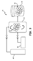
- FIG. 3 shows a simplified schematic diagram of second powder treatment apparatus 46 according to an alternate embodiment of the present disclosure.
- Second powder treatment apparatus 46 may include gas heater 48, surface treatment reactor 50, fluidized powder 52, second fluidized bed vessel 54, PDMS coated powder 56, and third storage vessel 58.
- Gas heater 48 prepares and heats a fluidization gas to be used to fluidize the powder within second fluidized bed vessel 54.
- Gas heater is fluidly connect to second fluidized bed vessel 54.
- Surface treatment reactor 50 is also fluidly connected to second fluidized bed vessel 54.
- Surface treatment reactor 50 provides a surface coating treatment to fluidized powder 52 while fluidized powder 52 is contained in second fluidized bed vessel 54.
- An example of the coating applied to fluidized powder 52 may include a PDMS coating.
- PDMS coated powder 56 is then stored in third storage vessel 58 until it is needed for an additive manufacturing process.
- gas heater 48 can be situated as shown in FIG. 2 .
- surface treatment reactor 50 can be situated as shown in FIG. 2 .
- a powder treatment method may include loading powder into a fluidized bed vessel. At least some of the powder may be fluidized in the fluidized bed vessel using an inert gas. While fluidized, the powder may be heated in the fluidized bed vessel. A surface treatment coating may be then applied to the powder.
- the powder treatment method of the preceding paragraph can optionally include, additionally and/or alternatively, any one or more of the following features, configurations and/or additional components:
- a powder treatment apparatus includes a fluidized bed vessel.
- a heat source for introducing heat in to the fluidized bed vessel is included in the powder treatment apparatus.
- Powder is disposed within the fluidized bed vessel.
- a surface treatment unit is fluidly connected to the fluidized bed vessel.
- the powder treatment apparatus of the preceding paragraph can optionally include, additionally and/or alternatively, any one or more of the following features, configurations and/or additional components:
- a powder treatment method may include loading powder into a fluidized bed vessel. At least some of the powder may be fluidized in the fluidized bed vessel using an inert gas. While fluidized, the powder may be heated in the fluidized bed vessel.
- a surface treatment coating may be applied to the powder.
- the surface treatment coating may include a siloxane based coating, a polymethylhydrosiloxane coating and combinations thereof, or a non-silicone based coating, including stearate salts, stearamides, copolymers of ethyl oxide and propylene oxide, and combinations thereof.
- the surface treatment coated powder may be then used to additively manufacture an article.
- the powder treatment method of the preceding paragraph can optionally include, additionally and/or alternatively, any one or more of the following features, configurations and/or additional components:
Landscapes
- Chemical & Material Sciences (AREA)
- Organic Chemistry (AREA)
- Engineering & Computer Science (AREA)
- Manufacturing & Machinery (AREA)
- Materials Engineering (AREA)
- Glanulating (AREA)
- Powder Metallurgy (AREA)
Abstract
Description
- The present invention relates to a surface treatment of powders. In particular, the invention relates to a surface treatment of powders to be used in additive manufacturing processes.
- Additive manufacturing is an established but growing technology. In its broadest definition, additive manufacturing is any layerwise construction or articles from thin layers of feed material. Additive manufacturing may involve applying liquid, layer, or particle material to a workstage, then sintering, curing, melting, and/or cutting to create a layer. The process is repeated up to several thousand times to construct the desired field finished component or article.
- Often times it is necessary to pre-treat raw powder used in some of the additive manufacturing processes. Pre-treatment may include coating, degassing and heat treating the powder. The powder particles can be coated in order to prevent oxidation of the particles during the additive manufacturing process. For example,
U.S. Patent No. 7,141,207 discloses applying a copper coating to aluminum powder. - Degassing can be used to remove water vapor from the powder particles. Surfaces of the powder can become oxidized very quickly during the manufacturing process when exposed to the environment. Water vapor can absorb into the oxide, which can cause voids in the material formed with the additive manufacturing process. Methods of removing water from the manufactured materials can cause the forming of hydrogen which can make the final material more brittle. Previous methods of removing water vapor from the powder include various methods of degassing. For example,
U.S. Pat. No. 5,976,456 describes a degassing method using heating aluminum powder in a vacuum to very high temperatures. However, complications can occur with maintaining a very low pressure vacuum during the degassing. - Additionally, traditional methods of high temperature heat treatment of gases can cause unwanted sintering of the powder. For example, fluidized beds have been used in conjunction with heat treating of powder to prevent agglomeration, as discussed in
U.S. Pat. No. 6,811,765 . - In particular, cold spray additive manufacturing requires removal of moisture and hydroxides on the surface of aluminum alloys at elevated temperatures to avoid detrimental effects in the final article such as blistering.
- A powder treatment method includes loading powder into a fluidized bed vessel. At least some of the powder is fluidized in the fluidized bed vessel using an inert gas. While fluidized, the powder is heated in the fluidized bed vessel. A surface treatment coating is then applied to the powder.
- A powder treatment apparatus includes a fluidized bed vessel. A heat source for introducing heat in to the fluidized bed vessel is included in the powder treatment apparatus. Powder is disposed within the fluidized bed vessel. A surface treatment unit is fluidly connected to the fluidized bed vessel.
- A powder treatment method includes loading powder into a fluidized bed vessel. At least some of the powder is fluidized in the fluidized bed vessel using an inert gas. While fluidized, the powder is heated in the fluidized bed vessel. A surface treatment coating is applied to the powder. The surface treatment coating includes a siloxane based coating. The surface treatment coated powder is then used to additively manufacture an article.
-
-
FIG. 1 is a schematic flow chart illustrating a powder treatment method. -
FIG. 2 is a simplified block diagram illustrating a powder treatment method. -
FIG. 3 is a simplified schematic diagram illustrating a powder treatment method according to an alternate embodiment. - The powder treatment method for cold-spray additive manufacturing in the present disclosure includes the surface treatment of powder particles to prevent the attachment or reactivity of water molecules, as well as increasing the flowability of the powder surfaces to prevent powder feeder blockages. The disclosed method provides a solution for these issues through the removal of high moisture levels by heat treatment followed by treatment of the powder particles surface with a chemical agent to prevent moisture reabsorption upon exposure to ambient conditions. The disclosed method allows for cost effective powder storage conditions, easier handling, and increased flowability. The disclosed method also provides for the availability of scalable processes to existing powder preparation methods.
- An example of a fluidized bed for degassing and heat treating powders is disclosed in
U.S. App. No. 61/815,359 (Nardi -
FIG. 1 shows a schematic block diagram ofpowder treatment method 10.Powder treatment method 10 includes a series of steps to prepare powder for use in an additive manufacturing process. Instep 12, the powder is loaded into a fluidized bed vessel.Step 14 involves fluidizing at least some of the powder in the fluidized bed vessel. Instep 16, the fluidized powder is heated in the fluidized bed vessel.Step 18 involves transferring the powder to a surface treatment unit. Alternatively, the same fluidized bed unit or assembly can be utilized to surface treat the powder.Step 20 includes applying a surface treatment coating to the powder. Instep 22, the powder is removed from the surface treatment unit to be stored in a storage container at ambient conditions.Step 24 involves additively manufacturing an article using the surface treatment coated powder. - With regards to
step 12, before the powder is loaded into the fluidized bed vessel, the powder may be received with significant amounts of absorbed or reacted moisture. The types of powders used may include metal alloy powders, non-metallic powders, magnetic powders, non-magnetic powders, ceramic powders, glass powders, or polymer powders. In an exemplary case the powder comprises metallic alloys such as aluminum alloys. Additional metallic alloys that can be utilized may include titanium alloys or copper alloys. - After the powder is loaded into the fluidized bed vessel, the powder is fluidized in
step 14. Fluidization of the powder occurs as the powder is entrained in a flow of inert gas. The fluidized powder may also be heat treated instep 16 either during the fluidization process or after the powder is fluidized. The range of temperatures and time periods used during the heating process may depend on the powder material. Temperatures used duringstep 16 for aluminum alloys can range up to 600° C. In general for metallic powders, it is desirable to heat the metallic powder to a temperature lower than its sintering temperature. -
Step 20 includes applying a surface treatment coating to the powder particles. The surface treatment coating may be applied to the powder by a surface treatment unit. The coating applied to the powder may be between 1 to 5 nm in thickness. The coatings may be siloxane based, and in particular comprise a polysiloxane coating, a polydimethylsiloxane ("PDMS") coating, a polymethylhydrosiloxane coating and combinations thereof, as well as non-silicone based coatings including stearate salts, stearamides, copolymers of ethyl oxide and propylene oxide, combinations thereof, or other chemistries commonly known to enhance the hydrophobic and/or flowability properties of a powder. Additionally, chemicals that are commonly known to increase electro-static repulsion may be applied to the powder to enhance the flowability of the powder. Applying the surface treatment coating to the powder may include subjecting the powder to an increased temperature for a period of time. Particularly, applying the surface treatment coating to the powder may include vaporizing PDMS and applying the vaporized PDMS to the powder. The surface coating treatment may increase the hydrophobic, flow, and slip properties of the powder so that the powder repels water and contains an increased capacity for flowability. Flowability may include the ability of the powder too flow at a given rate or for the particular powder particles to flow passed one another. A higher flow rate allows for less adhesion between particular powder particles and allows the powder to flow more freely through containers and passages. A low flow rate may be caused by a greater adhesion force between particular powder particles and cause the powder to flow less freely through containers and passages. Other properties affecting flow rate of a powder may include bulk density, friction coefficient, contact angle, permeability, and angle of repose. - Alternatively, the surface treatment coating may be applied while the powder remains in the fluidized bed vessel without transferring the powder to a surface treatment unit before applying a surface treatment coating to the powder.
- Coating the powder enables it to be stored in ambient and not tightly controlled and inerted conditions for longer periods of time before being used in an additive manufacturing process.
-
Step 22 includes removing the surface treatment coated powder from the surface treatment unit and moving it to a storage container.Step 24 includes additively manufacturing an article using the surface treatment coated powder. - In some embodiments,
powder treatment method 10 may be used to prepare powder for use in a cold spray deposition additive manufacturing process. In such a process, the powder is not melted such that the microstructure of the powder particle before the deposition process remains the same after a final article is formed. Thus, it becomes advantageous to manipulate the microstructure to a desirable state before the additive manufacturing process begins. In particular, cold spray deposition processes benefit from having powder particles that will deform well and that will bond well. In various embodiments, an inert gas, such as argon, can be used as the fluidizing gas. Simultaneously, the fluidizing gas can be used to clean the powder to facilitate bonding. Thus, in one embodiment, a hydrogen fluidizing gas can be used to remove oxides. In other embodiments, nitrogen or boron gas can be used to prevent the formation of oxidation on the powder. -
Powder treatment method 10 may allow for increased prevention of physical and chemical attachment of water on the powder through the manufacturing of hydrophobic layers on the powder. Storage of powders at ambient conditions without the need for a tightly controlled atmosphere is also enabled bypowder treatment method 10.Powder treatment method 10 may also eliminate the need of additional process requirements since the removal of the surface treatment or modifying agent can be completed under the conditions currently used in cold-spray processes. Furthermore, a steady stream of powder flow is facilitated bypowder treatment method 10 since the particles are prevented from agglomerating, resulting in reproducible and predictable coatings, increased additive manufacturing process control, and higher quality end products. In addition,powder treatment method 10 produces a higher range of utilizable powders for cold-spray and other additive manufacturing methods, and a scalable process through the incorporation of the surface treatment step to an existing fluidized bed vessel. -
FIG. 2 shows a simplified block diagram of firstpowder treatment apparatus 23. Firstpowder treatment apparatus 23 may include receivedpowder 24,first storage vessel 26, firstfluidized bed vessel 28,inert gas heater 29,surface treatment unit 30, surface coatedpowder 32,second storage vessel 34,powder feeder 36, cold-spray apparatusultrasonic nozzle 38, sprayedpowder 40,substrate 42, and/or spray-platform 44. -
Received powder 24 is stored infirst storage vessel 26.First storage vessel 26 is fluidly connected to firstfluidized bed vessel 28.Surface treatment unit 30 is fluidly connected to firstfluidized bed vessel 28. Surface coatedpowder 32 is located insecond storage vessel 34 which is fluidly connected to surfacetreatment unit 30.Powder feeder 36 is fluidly connected to cold-spray apparatusultrasonic nozzle 38. Sprayedpowder 40 is ejected from cold-spray apparatusultrasonic nozzle 38. Sprayedpowder 40 forms assubstrate 42 onto spray-platform 44. -
Received powder 24 is transferred fromfirst storage vessel 26 and loaded into firstfluidized bed vessel 28, where receivedpowder 24 is fluidized and heat treated by an inert gas stream. After the powder is heat treated it is transferred to surfacetreatment unit 30. -
Surface treatment unit 30 acts to provide the powder with a coating that enhances its hydrophobic and flowability properties as disclosed above.Surface treatment unit 30 may be disposed separately from first fluidized bed vessel 28 (as shown inFIG. 2 ), or alternatively can be integrated with and/or attached to firstfluidized bed vessel 28. - After the surface coated
powder 32 is removed fromsurface treatment unit 30, surface coatedpowder 32 is placed intosecond storage vessel 34, which may include an ambient atmosphere due to the increase hydrophobic properties of surface coatedpowder 32. - Upon initiation of an additive manufacturing process, surface coated
powder 32 is placed inpowder feeder 36.Powder feeder 36 feeds coatedpowder 32 to cold-spray apparatusultrasonic nozzle 38. Cold-spray apparatusultrasonic nozzle 38 then deposits coatedpowder 32 ontosubstrate 42 which forms on spray-platform 44. - The increased flowability of coated
powder 32 may enhance the contact angle, flow through an orifice, and angle of repose characteristics of coatedpowder 32. Enhancement in these characteristics preventscoated powder 32 from agglomeration during the additive manufacturing process. -
FIG. 3 shows a simplified schematic diagram of secondpowder treatment apparatus 46 according to an alternate embodiment of the present disclosure. Secondpowder treatment apparatus 46 may includegas heater 48,surface treatment reactor 50,fluidized powder 52, secondfluidized bed vessel 54, PDMS coatedpowder 56, andthird storage vessel 58. -
Gas heater 48 prepares and heats a fluidization gas to be used to fluidize the powder within secondfluidized bed vessel 54. Gas heater is fluidly connect to secondfluidized bed vessel 54.Surface treatment reactor 50 is also fluidly connected to secondfluidized bed vessel 54.Surface treatment reactor 50 provides a surface coating treatment to fluidizedpowder 52 whilefluidized powder 52 is contained in secondfluidized bed vessel 54. An example of the coating applied tofluidized powder 52 may include a PDMS coating. After the fluidization and coating steps are complete, PDMS coatedpowder 56 is then stored inthird storage vessel 58 until it is needed for an additive manufacturing process. - Alternatively, the locations of
gas heater 48,surface treatment reactor 50, and secondfluidized bed vessel 54 can be situated as shown inFIG. 2 . - The following are non-exclusive descriptions of possible embodiments of the present invention.
- A powder treatment method may include loading powder into a fluidized bed vessel. At least some of the powder may be fluidized in the fluidized bed vessel using an inert gas. While fluidized, the powder may be heated in the fluidized bed vessel. A surface treatment coating may be then applied to the powder.
- The powder treatment method of the preceding paragraph can optionally include, additionally and/or alternatively, any one or more of the following features, configurations and/or additional components:
- the surface treatment coating may comprise a siloxane based coating, a polymethylhydrosiloxane coating and combinations thereof, or a non-silicone based coating, including stearate salts, stearamides, copolymers of ethyl oxide and propylene oxide, and combinations thereof;
- the surface treatment coating may comprise a polydimethylsiloxane coating;
- the surface treatment coating may be configured to prevent agglomeration of the powder;
- the surface treatment coating may be configured to impart hydrophobic properties onto the powder;
- heating of the powder may include raising the temperature of the inert gas by an inert gas heater, wherein the inert gas is selected from the group consisting of nitrogen, hydrogen, boron, and argon;
- heating of the powder may include raising the temperature of the powder to a temperature below a sintering temperature of the powder;
- transferring the powder to a surface treatment unit before applying the surface coating treatment to the powder; and
- additively manufacturing an article using a surface treatment coated powder.
- A powder treatment apparatus includes a fluidized bed vessel. A heat source for introducing heat in to the fluidized bed vessel is included in the powder treatment apparatus. Powder is disposed within the fluidized bed vessel. A surface treatment unit is fluidly connected to the fluidized bed vessel.
- The powder treatment apparatus of the preceding paragraph can optionally include, additionally and/or alternatively, any one or more of the following features, configurations and/or additional components:
- a storage vessel may be fluidly connected to the surface treatment unit;
- the surface treatment unit may be configured to apply a surface treatment coating to a powder;
- the fluidized bed vessel may be configured to receive an inert gas; and
- the inert gas may be selected from the group consisting of nitrogen, hydrogen, boron, and argon.
- A powder treatment method may include loading powder into a fluidized bed vessel. At least some of the powder may be fluidized in the fluidized bed vessel using an inert gas. While fluidized, the powder may be heated in the fluidized bed vessel. A surface treatment coating may be applied to the powder. The surface treatment coating may include a siloxane based coating, a polymethylhydrosiloxane coating and combinations thereof, or a non-silicone based coating, including stearate salts, stearamides, copolymers of ethyl oxide and propylene oxide, and combinations thereof. The surface treatment coated powder may be then used to additively manufacture an article.
- The powder treatment method of the preceding paragraph can optionally include, additionally and/or alternatively, any one or more of the following features, configurations and/or additional components:
- the powder may be selected from the group consisting of metal, ceramic, glass, and polymer powder;
- the surface treatment coating may be configured to prevent agglomeration of the powder; and
- the surface treatment coating may be configured to impart hydrophobic properties onto the powder.
- While the invention has been described with reference to an exemplary embodiment(s), it will be understood by those skilled in the art that various changes may be made and equivalents may be substituted for elements thereof without departing from the scope of the invention. In addition, many modifications may be made to adapt a particular situation or material to the teachings of the invention without departing from the essential scope thereof. Therefore, it is intended that the invention not be limited to the particular embodiment(s) disclosed, but that the invention will include all embodiments falling within the scope of the appended claims.
Claims (15)
- A powder treatment method comprising:loading a powder into a fluidized bed vessel;fluidizing at least some of the powder in the fluidized bed vessel using an inert gas;heating the powder while fluidized in the fluidized bed vessel; andapplying a surface treatment coating to the powder.
- The method of claim 1, wherein the surface treatment coating comprises:a siloxane based coating, a polymethylhydrosiloxane coating or combinations thereof; ora non-silicone based coating, including stearate salts, stearamides, copolymers of ethyl oxide and propylene oxide, or combinations thereof
- The method of claim 1 or 2, wherein the surface treatment coating comprises a polydimethylsiloxane coating.
- The method of any of claims 1 to 3, wherein the surface treatment coating is configured to prevent agglomeration of the powder.
- The method of any preceding claim, wherein the surface treatment coating is configured to impart hydrophobic properties onto the powder.
- The method of any preceding claim, wherein heating the powder comprises raising the temperature of the inert gas by an inert gas heater, wherein the inert gas is selected from the group consisting of nitrogen, hydrogen, boron, and argon.
- The method of any preceding claim, wherein heating the powder comprises raising the temperature of the powder to a temperature below a sintering temperature of the powder.
- The method of any preceding claim, further comprising transferring the powder to a surface treatment unit before applying the surface coating treatment to the powder.
- The method of any preceding claim, further comprising additively manufacturing an article using a surface treatment coated powder.
- The method of any preceding claim, wherein the powder is selected from the group consisting of metal, ceramic, glass, and polymer powder.
- A powder treatment apparatus comprising:a fluidized bed vessel;a heat source configured to introduce heat into the fluidized bed vessel; anda surface treatment unit fluidly connected to the fluidized bed vessel.
- The apparatus of claim 11, further comprising a storage vessel fluidly connected to the surface treatment unit.
- The apparatus of claim 11 or 12, wherein the surface treatment unit is configured to apply a surface treatment coating to a powder.
- The apparatus of any of claims 11 to 13, wherein the fluidized bed vessel is configured to receive an inert gas.
- The apparatus of claim 14, wherein the inert gas is nitrogen, hydrogen, boron or argon.
Applications Claiming Priority (1)
| Application Number | Priority Date | Filing Date | Title |
|---|---|---|---|
| US201461990954P | 2014-05-09 | 2014-05-09 |
Publications (2)
| Publication Number | Publication Date |
|---|---|
| EP2942373A1 true EP2942373A1 (en) | 2015-11-11 |
| EP2942373B1 EP2942373B1 (en) | 2024-01-24 |
Family
ID=53174878
Family Applications (1)
| Application Number | Title | Priority Date | Filing Date |
|---|---|---|---|
| EP15167218.5A Active EP2942373B1 (en) | 2014-05-09 | 2015-05-11 | Surface treatment of powders |
Country Status (2)
| Country | Link |
|---|---|
| US (2) | US10058918B2 (en) |
| EP (1) | EP2942373B1 (en) |
Cited By (2)
| Publication number | Priority date | Publication date | Assignee | Title |
|---|---|---|---|---|
| EP3248714A1 (en) * | 2016-05-26 | 2017-11-29 | United Technologies Corporation | Powder processing system and method for powder heat treatment |
| EP3348670A1 (en) * | 2017-01-13 | 2018-07-18 | United Technologies Corporation | Cold spray system with variable tailored feedstock cartridges |
Families Citing this family (9)
| Publication number | Priority date | Publication date | Assignee | Title |
|---|---|---|---|---|
| US10041171B2 (en) * | 2015-08-10 | 2018-08-07 | Delavan Inc. | Particulates for additive manufacturing techniques |
| US10576541B2 (en) | 2016-06-22 | 2020-03-03 | United Technologies Corporation | Structured powder particles for feedstock improvement for laser based additive manufacturing |
| US10626503B2 (en) | 2016-08-18 | 2020-04-21 | Hamilton Sundstrand Corporation | Particulates and methods of making particulates |
| CA3098314C (en) * | 2016-09-07 | 2022-04-12 | Tessonics, Inc. | Hopper with microreactor and cartridge for low pressure cold spraying |
| EP3634718B1 (en) * | 2017-07-20 | 2022-12-14 | Hewlett-Packard Development Company, L.P. | Build material recycling system and method of a three-dimensional (3d) printer |
| CN113195127A (en) | 2018-12-14 | 2021-07-30 | 速尔特技术有限公司 | Additive manufacturing system for creating objects from powder using high-throughput laser for two-dimensional printing |
| CN118439623A (en) * | 2019-02-21 | 2024-08-06 | 三菱化学株式会社 | Silica particles and method for producing same, silanol group measurement method, polishing composition, polishing method, method for producing semiconductor wafer, and method for producing semiconductor device |
| US12599962B2 (en) | 2020-01-30 | 2026-04-14 | Ap&C Advanced Powders & Coatings Inc. | System and method for treating additive powder |
| CN115230147B (en) * | 2022-07-22 | 2025-12-05 | 南京航空航天大学 | An integrated drying and powder feeding device and method for high-quality laser additive manufacturing |
Citations (5)
| Publication number | Priority date | Publication date | Assignee | Title |
|---|---|---|---|---|
| DE2454138A1 (en) * | 1973-11-22 | 1975-05-28 | Int Standard Electric Corp | Coating powder particles in fluidised bed - using gas phase reaction in bed to form coating |
| EP0924269A1 (en) * | 1997-12-22 | 1999-06-23 | Degussa Aktiengesellschaft | Hydrophobic, pyrogenically prepared oxides |
| US5976456A (en) | 1998-03-12 | 1999-11-02 | National Research Council Of Canada | Method for producing aluminum alloy powder compacts |
| US6811765B1 (en) | 1997-11-14 | 2004-11-02 | Epion Corporation | Thermal treatment of fine grain materials in a coarse-grain fluidized bed |
| US7141207B2 (en) | 2004-08-30 | 2006-11-28 | General Motors Corporation | Aluminum/magnesium 3D-Printing rapid prototyping |
Family Cites Families (3)
| Publication number | Priority date | Publication date | Assignee | Title |
|---|---|---|---|---|
| US6316050B1 (en) * | 1997-12-22 | 2001-11-13 | Degussa | Method of producing hydrophobic pyrogenically produced oxides |
| WO2007045000A2 (en) * | 2005-10-14 | 2007-04-19 | Vantus Technology Corporation | Personal fit medical implants and orthopedic surgical instruments and methods for making |
| DE102007055879A1 (en) * | 2007-12-19 | 2009-06-25 | Wacker Chemie Ag | Hydrophobization of silicas and oxidizing conditions |
-
2015
- 2015-04-28 US US14/697,853 patent/US10058918B2/en active Active
- 2015-05-11 EP EP15167218.5A patent/EP2942373B1/en active Active
-
2018
- 2018-07-27 US US16/047,332 patent/US20180339336A1/en not_active Abandoned
Patent Citations (5)
| Publication number | Priority date | Publication date | Assignee | Title |
|---|---|---|---|---|
| DE2454138A1 (en) * | 1973-11-22 | 1975-05-28 | Int Standard Electric Corp | Coating powder particles in fluidised bed - using gas phase reaction in bed to form coating |
| US6811765B1 (en) | 1997-11-14 | 2004-11-02 | Epion Corporation | Thermal treatment of fine grain materials in a coarse-grain fluidized bed |
| EP0924269A1 (en) * | 1997-12-22 | 1999-06-23 | Degussa Aktiengesellschaft | Hydrophobic, pyrogenically prepared oxides |
| US5976456A (en) | 1998-03-12 | 1999-11-02 | National Research Council Of Canada | Method for producing aluminum alloy powder compacts |
| US7141207B2 (en) | 2004-08-30 | 2006-11-28 | General Motors Corporation | Aluminum/magnesium 3D-Printing rapid prototyping |
Cited By (3)
| Publication number | Priority date | Publication date | Assignee | Title |
|---|---|---|---|---|
| EP3248714A1 (en) * | 2016-05-26 | 2017-11-29 | United Technologies Corporation | Powder processing system and method for powder heat treatment |
| EP3348670A1 (en) * | 2017-01-13 | 2018-07-18 | United Technologies Corporation | Cold spray system with variable tailored feedstock cartridges |
| US10226791B2 (en) | 2017-01-13 | 2019-03-12 | United Technologies Corporation | Cold spray system with variable tailored feedstock cartridges |
Also Published As
| Publication number | Publication date |
|---|---|
| US10058918B2 (en) | 2018-08-28 |
| US20150321253A1 (en) | 2015-11-12 |
| EP2942373B1 (en) | 2024-01-24 |
| US20180339336A1 (en) | 2018-11-29 |
Similar Documents
| Publication | Publication Date | Title |
|---|---|---|
| EP2942373B1 (en) | Surface treatment of powders | |
| US20250250681A1 (en) | Use of reactive fluids in additive manufacturing and the products made therefrom | |
| EP2988895B1 (en) | Fluidized bed for degassing and heat treating powders | |
| CN105377476B (en) | For the high temperature fluidized bed of powder-processed | |
| US8591986B1 (en) | Cold spray deposition method | |
| US9732422B2 (en) | Method of coating metallic powder particles | |
| US9938624B2 (en) | Method for enhancing bond strength through in-situ peening | |
| US8080278B2 (en) | Cold gas spraying method | |
| EP3348670B1 (en) | Cold spray system with variable tailored feedstock cartridges | |
| EP3254784A1 (en) | Method of coating metallic powder particles with silicon | |
| CN109338264B (en) | Preparation method and system of metal alloy coating in atmospheric atmosphere | |
| US3644133A (en) | Layer lattice structured dry lubricant coating method | |
| CN111690925B (en) | A kind of titanium and titanium alloy surface hardening and surface functionalization treatment process | |
| CA3003981C (en) | Apparatus and method for cold spraying and coating processing | |
| EP3248714A1 (en) | Powder processing system and method for powder heat treatment | |
| JP2021059754A (en) | Method of manufacturing magnetic particle formation | |
| Moghtaderi et al. | Combustion prevention of iron powders by a novel coating method | |
| WO2015019316A2 (en) | Method for forming a coating on a solid substrate, and article thus obtained | |
| CN106222600A (en) | A kind of method that atmospheric environment moderate supersonic speed plasma spraying prepares Ti TiN gradient coating | |
| JP2016140864A5 (en) | ||
| JP2015151622A (en) | Powder for flame spray, production method of powder for flame spray, and production method of sprayed coating | |
| KR20140082085A (en) | Thermal spray coating method for amorphous phase metal coating |
Legal Events
| Date | Code | Title | Description |
|---|---|---|---|
| PUAI | Public reference made under article 153(3) epc to a published international application that has entered the european phase |
Free format text: ORIGINAL CODE: 0009012 |
|
| AK | Designated contracting states |
Kind code of ref document: A1 Designated state(s): AL AT BE BG CH CY CZ DE DK EE ES FI FR GB GR HR HU IE IS IT LI LT LU LV MC MK MT NL NO PL PT RO RS SE SI SK SM TR |
|
| AX | Request for extension of the european patent |
Extension state: BA ME |
|
| 17P | Request for examination filed |
Effective date: 20160418 |
|
| RBV | Designated contracting states (corrected) |
Designated state(s): AL AT BE BG CH CY CZ DE DK EE ES FI FR GB GR HR HU IE IS IT LI LT LU LV MC MK MT NL NO PL PT RO RS SE SI SK SM TR |
|
| RAP1 | Party data changed (applicant data changed or rights of an application transferred) |
Owner name: UNITED TECHNOLOGIES CORPORATION |
|
| STAA | Information on the status of an ep patent application or granted ep patent |
Free format text: STATUS: EXAMINATION IS IN PROGRESS |
|
| 17Q | First examination report despatched |
Effective date: 20161028 |
|
| RAP1 | Party data changed (applicant data changed or rights of an application transferred) |
Owner name: RAYTHEON TECHNOLOGIES CORPORATION |
|
| RIC1 | Information provided on ipc code assigned before grant |
Ipc: B33Y 40/10 20200101ALI20230724BHEP Ipc: B22F 1/102 20220101ALI20230724BHEP Ipc: C09C 1/64 20060101ALI20230724BHEP Ipc: C09C 3/12 20060101ALI20230724BHEP Ipc: C09C 1/62 20060101AFI20230724BHEP |
|
| GRAP | Despatch of communication of intention to grant a patent |
Free format text: ORIGINAL CODE: EPIDOSNIGR1 |
|
| STAA | Information on the status of an ep patent application or granted ep patent |
Free format text: STATUS: GRANT OF PATENT IS INTENDED |
|
| INTG | Intention to grant announced |
Effective date: 20230906 |
|
| RAP3 | Party data changed (applicant data changed or rights of an application transferred) |
Owner name: RTX CORPORATION |
|
| GRAS | Grant fee paid |
Free format text: ORIGINAL CODE: EPIDOSNIGR3 |
|
| GRAA | (expected) grant |
Free format text: ORIGINAL CODE: 0009210 |
|
| STAA | Information on the status of an ep patent application or granted ep patent |
Free format text: STATUS: THE PATENT HAS BEEN GRANTED |
|
| AK | Designated contracting states |
Kind code of ref document: B1 Designated state(s): AL AT BE BG CH CY CZ DE DK EE ES FI FR GB GR HR HU IE IS IT LI LT LU LV MC MK MT NL NO PL PT RO RS SE SI SK SM TR |
|
| REG | Reference to a national code |
Ref country code: GB Ref legal event code: FG4D |
|
| REG | Reference to a national code |
Ref country code: CH Ref legal event code: EP |
|
| REG | Reference to a national code |
Ref country code: IE Ref legal event code: FG4D |
|
| REG | Reference to a national code |
Ref country code: DE Ref legal event code: R096 Ref document number: 602015087345 Country of ref document: DE |
|
| REG | Reference to a national code |
Ref country code: LT Ref legal event code: MG9D |
|
| REG | Reference to a national code |
Ref country code: NL Ref legal event code: MP Effective date: 20240124 |
|
| PG25 | Lapsed in a contracting state [announced via postgrant information from national office to epo] |
Ref country code: NL Free format text: LAPSE BECAUSE OF FAILURE TO SUBMIT A TRANSLATION OF THE DESCRIPTION OR TO PAY THE FEE WITHIN THE PRESCRIBED TIME-LIMIT Effective date: 20240124 |
|
| PG25 | Lapsed in a contracting state [announced via postgrant information from national office to epo] |
Ref country code: NL Free format text: LAPSE BECAUSE OF FAILURE TO SUBMIT A TRANSLATION OF THE DESCRIPTION OR TO PAY THE FEE WITHIN THE PRESCRIBED TIME-LIMIT Effective date: 20240124 |
|
| PG25 | Lapsed in a contracting state [announced via postgrant information from national office to epo] |
Ref country code: IS Free format text: LAPSE BECAUSE OF FAILURE TO SUBMIT A TRANSLATION OF THE DESCRIPTION OR TO PAY THE FEE WITHIN THE PRESCRIBED TIME-LIMIT Effective date: 20240524 |
|
| PG25 | Lapsed in a contracting state [announced via postgrant information from national office to epo] |
Ref country code: LT Free format text: LAPSE BECAUSE OF FAILURE TO SUBMIT A TRANSLATION OF THE DESCRIPTION OR TO PAY THE FEE WITHIN THE PRESCRIBED TIME-LIMIT Effective date: 20240124 |
|
| PG25 | Lapsed in a contracting state [announced via postgrant information from national office to epo] |
Ref country code: GR Free format text: LAPSE BECAUSE OF FAILURE TO SUBMIT A TRANSLATION OF THE DESCRIPTION OR TO PAY THE FEE WITHIN THE PRESCRIBED TIME-LIMIT Effective date: 20240425 |
|
| REG | Reference to a national code |
Ref country code: AT Ref legal event code: MK05 Ref document number: 1652196 Country of ref document: AT Kind code of ref document: T Effective date: 20240124 |
|
| PG25 | Lapsed in a contracting state [announced via postgrant information from national office to epo] |
Ref country code: RS Free format text: LAPSE BECAUSE OF FAILURE TO SUBMIT A TRANSLATION OF THE DESCRIPTION OR TO PAY THE FEE WITHIN THE PRESCRIBED TIME-LIMIT Effective date: 20240424 Ref country code: HR Free format text: LAPSE BECAUSE OF FAILURE TO SUBMIT A TRANSLATION OF THE DESCRIPTION OR TO PAY THE FEE WITHIN THE PRESCRIBED TIME-LIMIT Effective date: 20240124 |
|
| PG25 | Lapsed in a contracting state [announced via postgrant information from national office to epo] |
Ref country code: ES Free format text: LAPSE BECAUSE OF FAILURE TO SUBMIT A TRANSLATION OF THE DESCRIPTION OR TO PAY THE FEE WITHIN THE PRESCRIBED TIME-LIMIT Effective date: 20240124 |
|
| PG25 | Lapsed in a contracting state [announced via postgrant information from national office to epo] |
Ref country code: AT Free format text: LAPSE BECAUSE OF FAILURE TO SUBMIT A TRANSLATION OF THE DESCRIPTION OR TO PAY THE FEE WITHIN THE PRESCRIBED TIME-LIMIT Effective date: 20240124 |
|
| PG25 | Lapsed in a contracting state [announced via postgrant information from national office to epo] |
Ref country code: RS Free format text: LAPSE BECAUSE OF FAILURE TO SUBMIT A TRANSLATION OF THE DESCRIPTION OR TO PAY THE FEE WITHIN THE PRESCRIBED TIME-LIMIT Effective date: 20240424 Ref country code: NO Free format text: LAPSE BECAUSE OF FAILURE TO SUBMIT A TRANSLATION OF THE DESCRIPTION OR TO PAY THE FEE WITHIN THE PRESCRIBED TIME-LIMIT Effective date: 20240424 Ref country code: LT Free format text: LAPSE BECAUSE OF FAILURE TO SUBMIT A TRANSLATION OF THE DESCRIPTION OR TO PAY THE FEE WITHIN THE PRESCRIBED TIME-LIMIT Effective date: 20240124 Ref country code: IS Free format text: LAPSE BECAUSE OF FAILURE TO SUBMIT A TRANSLATION OF THE DESCRIPTION OR TO PAY THE FEE WITHIN THE PRESCRIBED TIME-LIMIT Effective date: 20240524 Ref country code: HR Free format text: LAPSE BECAUSE OF FAILURE TO SUBMIT A TRANSLATION OF THE DESCRIPTION OR TO PAY THE FEE WITHIN THE PRESCRIBED TIME-LIMIT Effective date: 20240124 Ref country code: GR Free format text: LAPSE BECAUSE OF FAILURE TO SUBMIT A TRANSLATION OF THE DESCRIPTION OR TO PAY THE FEE WITHIN THE PRESCRIBED TIME-LIMIT Effective date: 20240425 Ref country code: FI Free format text: LAPSE BECAUSE OF FAILURE TO SUBMIT A TRANSLATION OF THE DESCRIPTION OR TO PAY THE FEE WITHIN THE PRESCRIBED TIME-LIMIT Effective date: 20240124 Ref country code: ES Free format text: LAPSE BECAUSE OF FAILURE TO SUBMIT A TRANSLATION OF THE DESCRIPTION OR TO PAY THE FEE WITHIN THE PRESCRIBED TIME-LIMIT Effective date: 20240124 Ref country code: BG Free format text: LAPSE BECAUSE OF FAILURE TO SUBMIT A TRANSLATION OF THE DESCRIPTION OR TO PAY THE FEE WITHIN THE PRESCRIBED TIME-LIMIT Effective date: 20240124 Ref country code: AT Free format text: LAPSE BECAUSE OF FAILURE TO SUBMIT A TRANSLATION OF THE DESCRIPTION OR TO PAY THE FEE WITHIN THE PRESCRIBED TIME-LIMIT Effective date: 20240124 |
|
| PG25 | Lapsed in a contracting state [announced via postgrant information from national office to epo] |
Ref country code: PT Free format text: LAPSE BECAUSE OF FAILURE TO SUBMIT A TRANSLATION OF THE DESCRIPTION OR TO PAY THE FEE WITHIN THE PRESCRIBED TIME-LIMIT Effective date: 20240524 Ref country code: PL Free format text: LAPSE BECAUSE OF FAILURE TO SUBMIT A TRANSLATION OF THE DESCRIPTION OR TO PAY THE FEE WITHIN THE PRESCRIBED TIME-LIMIT Effective date: 20240124 |
|
| PG25 | Lapsed in a contracting state [announced via postgrant information from national office to epo] |
Ref country code: SE Free format text: LAPSE BECAUSE OF FAILURE TO SUBMIT A TRANSLATION OF THE DESCRIPTION OR TO PAY THE FEE WITHIN THE PRESCRIBED TIME-LIMIT Effective date: 20240124 Ref country code: PT Free format text: LAPSE BECAUSE OF FAILURE TO SUBMIT A TRANSLATION OF THE DESCRIPTION OR TO PAY THE FEE WITHIN THE PRESCRIBED TIME-LIMIT Effective date: 20240524 Ref country code: PL Free format text: LAPSE BECAUSE OF FAILURE TO SUBMIT A TRANSLATION OF THE DESCRIPTION OR TO PAY THE FEE WITHIN THE PRESCRIBED TIME-LIMIT Effective date: 20240124 Ref country code: LV Free format text: LAPSE BECAUSE OF FAILURE TO SUBMIT A TRANSLATION OF THE DESCRIPTION OR TO PAY THE FEE WITHIN THE PRESCRIBED TIME-LIMIT Effective date: 20240124 |
|
| PG25 | Lapsed in a contracting state [announced via postgrant information from national office to epo] |
Ref country code: DK Free format text: LAPSE BECAUSE OF FAILURE TO SUBMIT A TRANSLATION OF THE DESCRIPTION OR TO PAY THE FEE WITHIN THE PRESCRIBED TIME-LIMIT Effective date: 20240124 |
|
| PG25 | Lapsed in a contracting state [announced via postgrant information from national office to epo] |
Ref country code: SM Free format text: LAPSE BECAUSE OF FAILURE TO SUBMIT A TRANSLATION OF THE DESCRIPTION OR TO PAY THE FEE WITHIN THE PRESCRIBED TIME-LIMIT Effective date: 20240124 |
|
| PG25 | Lapsed in a contracting state [announced via postgrant information from national office to epo] |
Ref country code: EE Free format text: LAPSE BECAUSE OF FAILURE TO SUBMIT A TRANSLATION OF THE DESCRIPTION OR TO PAY THE FEE WITHIN THE PRESCRIBED TIME-LIMIT Effective date: 20240124 Ref country code: CZ Free format text: LAPSE BECAUSE OF FAILURE TO SUBMIT A TRANSLATION OF THE DESCRIPTION OR TO PAY THE FEE WITHIN THE PRESCRIBED TIME-LIMIT Effective date: 20240124 |
|
| REG | Reference to a national code |
Ref country code: DE Ref legal event code: R097 Ref document number: 602015087345 Country of ref document: DE |
|
| PG25 | Lapsed in a contracting state [announced via postgrant information from national office to epo] |
Ref country code: SK Free format text: LAPSE BECAUSE OF FAILURE TO SUBMIT A TRANSLATION OF THE DESCRIPTION OR TO PAY THE FEE WITHIN THE PRESCRIBED TIME-LIMIT Effective date: 20240124 |
|
| PG25 | Lapsed in a contracting state [announced via postgrant information from national office to epo] |
Ref country code: SM Free format text: LAPSE BECAUSE OF FAILURE TO SUBMIT A TRANSLATION OF THE DESCRIPTION OR TO PAY THE FEE WITHIN THE PRESCRIBED TIME-LIMIT Effective date: 20240124 Ref country code: SK Free format text: LAPSE BECAUSE OF FAILURE TO SUBMIT A TRANSLATION OF THE DESCRIPTION OR TO PAY THE FEE WITHIN THE PRESCRIBED TIME-LIMIT Effective date: 20240124 Ref country code: RO Free format text: LAPSE BECAUSE OF FAILURE TO SUBMIT A TRANSLATION OF THE DESCRIPTION OR TO PAY THE FEE WITHIN THE PRESCRIBED TIME-LIMIT Effective date: 20240124 Ref country code: EE Free format text: LAPSE BECAUSE OF FAILURE TO SUBMIT A TRANSLATION OF THE DESCRIPTION OR TO PAY THE FEE WITHIN THE PRESCRIBED TIME-LIMIT Effective date: 20240124 Ref country code: DK Free format text: LAPSE BECAUSE OF FAILURE TO SUBMIT A TRANSLATION OF THE DESCRIPTION OR TO PAY THE FEE WITHIN THE PRESCRIBED TIME-LIMIT Effective date: 20240124 Ref country code: CZ Free format text: LAPSE BECAUSE OF FAILURE TO SUBMIT A TRANSLATION OF THE DESCRIPTION OR TO PAY THE FEE WITHIN THE PRESCRIBED TIME-LIMIT Effective date: 20240124 |
|
| PLBE | No opposition filed within time limit |
Free format text: ORIGINAL CODE: 0009261 |
|
| STAA | Information on the status of an ep patent application or granted ep patent |
Free format text: STATUS: NO OPPOSITION FILED WITHIN TIME LIMIT |
|
| PG25 | Lapsed in a contracting state [announced via postgrant information from national office to epo] |
Ref country code: IT Free format text: LAPSE BECAUSE OF FAILURE TO SUBMIT A TRANSLATION OF THE DESCRIPTION OR TO PAY THE FEE WITHIN THE PRESCRIBED TIME-LIMIT Effective date: 20240124 |
|
| REG | Reference to a national code |
Ref country code: CH Ref legal event code: PL |
|
| PG25 | Lapsed in a contracting state [announced via postgrant information from national office to epo] |
Ref country code: IT Free format text: LAPSE BECAUSE OF FAILURE TO SUBMIT A TRANSLATION OF THE DESCRIPTION OR TO PAY THE FEE WITHIN THE PRESCRIBED TIME-LIMIT Effective date: 20240124 |
|
| 26N | No opposition filed |
Effective date: 20241025 |
|
| PG25 | Lapsed in a contracting state [announced via postgrant information from national office to epo] |
Ref country code: MC Free format text: LAPSE BECAUSE OF FAILURE TO SUBMIT A TRANSLATION OF THE DESCRIPTION OR TO PAY THE FEE WITHIN THE PRESCRIBED TIME-LIMIT Effective date: 20240124 |
|
| PG25 | Lapsed in a contracting state [announced via postgrant information from national office to epo] |
Ref country code: LU Free format text: LAPSE BECAUSE OF NON-PAYMENT OF DUE FEES Effective date: 20240511 |
|
| PG25 | Lapsed in a contracting state [announced via postgrant information from national office to epo] |
Ref country code: MC Free format text: LAPSE BECAUSE OF FAILURE TO SUBMIT A TRANSLATION OF THE DESCRIPTION OR TO PAY THE FEE WITHIN THE PRESCRIBED TIME-LIMIT Effective date: 20240124 Ref country code: LU Free format text: LAPSE BECAUSE OF NON-PAYMENT OF DUE FEES Effective date: 20240511 Ref country code: CH Free format text: LAPSE BECAUSE OF NON-PAYMENT OF DUE FEES Effective date: 20240531 |
|
| REG | Reference to a national code |
Ref country code: BE Ref legal event code: MM Effective date: 20240531 |
|
| PG25 | Lapsed in a contracting state [announced via postgrant information from national office to epo] |
Ref country code: IE Free format text: LAPSE BECAUSE OF NON-PAYMENT OF DUE FEES Effective date: 20240511 |
|
| PG25 | Lapsed in a contracting state [announced via postgrant information from national office to epo] |
Ref country code: SI Free format text: LAPSE BECAUSE OF FAILURE TO SUBMIT A TRANSLATION OF THE DESCRIPTION OR TO PAY THE FEE WITHIN THE PRESCRIBED TIME-LIMIT Effective date: 20240124 Ref country code: BE Free format text: LAPSE BECAUSE OF NON-PAYMENT OF DUE FEES Effective date: 20240531 |
|
| PGFP | Annual fee paid to national office [announced via postgrant information from national office to epo] |
Ref country code: DE Payment date: 20250423 Year of fee payment: 11 |
|
| PGFP | Annual fee paid to national office [announced via postgrant information from national office to epo] |
Ref country code: GB Payment date: 20250423 Year of fee payment: 11 |
|
| PGFP | Annual fee paid to national office [announced via postgrant information from national office to epo] |
Ref country code: FR Payment date: 20250424 Year of fee payment: 11 |
|
| PG25 | Lapsed in a contracting state [announced via postgrant information from national office to epo] |
Ref country code: CY Free format text: LAPSE BECAUSE OF FAILURE TO SUBMIT A TRANSLATION OF THE DESCRIPTION OR TO PAY THE FEE WITHIN THE PRESCRIBED TIME-LIMIT; INVALID AB INITIO Effective date: 20150511 |
|
| PG25 | Lapsed in a contracting state [announced via postgrant information from national office to epo] |
Ref country code: HU Free format text: LAPSE BECAUSE OF FAILURE TO SUBMIT A TRANSLATION OF THE DESCRIPTION OR TO PAY THE FEE WITHIN THE PRESCRIBED TIME-LIMIT; INVALID AB INITIO Effective date: 20150511 |