EP2942305A1 - Hinged-lid package - Google Patents
Hinged-lid package Download PDFInfo
- Publication number
- EP2942305A1 EP2942305A1 EP12891060.1A EP12891060A EP2942305A1 EP 2942305 A1 EP2942305 A1 EP 2942305A1 EP 12891060 A EP12891060 A EP 12891060A EP 2942305 A1 EP2942305 A1 EP 2942305A1
- Authority
- EP
- European Patent Office
- Prior art keywords
- lid
- package
- wall
- edge
- front side
- Prior art date
- Legal status (The legal status is an assumption and is not a legal conclusion. Google has not performed a legal analysis and makes no representation as to the accuracy of the status listed.)
- Withdrawn
Links
Images






Classifications
-
- B—PERFORMING OPERATIONS; TRANSPORTING
- B65—CONVEYING; PACKING; STORING; HANDLING THIN OR FILAMENTARY MATERIAL
- B65D—CONTAINERS FOR STORAGE OR TRANSPORT OF ARTICLES OR MATERIALS, e.g. BAGS, BARRELS, BOTTLES, BOXES, CANS, CARTONS, CRATES, DRUMS, JARS, TANKS, HOPPERS, FORWARDING CONTAINERS; ACCESSORIES, CLOSURES, OR FITTINGS THEREFOR; PACKAGING ELEMENTS; PACKAGES
- B65D85/00—Containers, packaging elements or packages, specially adapted for particular articles or materials
- B65D85/07—Containers, packaging elements or packages, specially adapted for particular articles or materials for compressible or flexible articles
- B65D85/08—Containers, packaging elements or packages, specially adapted for particular articles or materials for compressible or flexible articles rod-shaped or tubular
- B65D85/10—Containers, packaging elements or packages, specially adapted for particular articles or materials for compressible or flexible articles rod-shaped or tubular for cigarettes
- B65D85/1036—Containers formed by erecting a rigid or semi-rigid blank
- B65D85/1045—Containers formed by erecting a rigid or semi-rigid blank having a cap-like lid hinged to an edge
-
- B—PERFORMING OPERATIONS; TRANSPORTING
- B65—CONVEYING; PACKING; STORING; HANDLING THIN OR FILAMENTARY MATERIAL
- B65D—CONTAINERS FOR STORAGE OR TRANSPORT OF ARTICLES OR MATERIALS, e.g. BAGS, BARRELS, BOTTLES, BOXES, CANS, CARTONS, CRATES, DRUMS, JARS, TANKS, HOPPERS, FORWARDING CONTAINERS; ACCESSORIES, CLOSURES, OR FITTINGS THEREFOR; PACKAGING ELEMENTS; PACKAGES
- B65D85/00—Containers, packaging elements or packages, specially adapted for particular articles or materials
- B65D85/07—Containers, packaging elements or packages, specially adapted for particular articles or materials for compressible or flexible articles
- B65D85/08—Containers, packaging elements or packages, specially adapted for particular articles or materials for compressible or flexible articles rod-shaped or tubular
- B65D85/10—Containers, packaging elements or packages, specially adapted for particular articles or materials for compressible or flexible articles rod-shaped or tubular for cigarettes
- B65D85/1036—Containers formed by erecting a rigid or semi-rigid blank
- B65D85/1045—Containers formed by erecting a rigid or semi-rigid blank having a cap-like lid hinged to an edge
- B65D85/1048—Containers formed by erecting a rigid or semi-rigid blank having a cap-like lid hinged to an edge characterized by the shape of the container
-
- B—PERFORMING OPERATIONS; TRANSPORTING
- B65—CONVEYING; PACKING; STORING; HANDLING THIN OR FILAMENTARY MATERIAL
- B65D—CONTAINERS FOR STORAGE OR TRANSPORT OF ARTICLES OR MATERIALS, e.g. BAGS, BARRELS, BOTTLES, BOXES, CANS, CARTONS, CRATES, DRUMS, JARS, TANKS, HOPPERS, FORWARDING CONTAINERS; ACCESSORIES, CLOSURES, OR FITTINGS THEREFOR; PACKAGING ELEMENTS; PACKAGES
- B65D85/00—Containers, packaging elements or packages, specially adapted for particular articles or materials
- B65D85/07—Containers, packaging elements or packages, specially adapted for particular articles or materials for compressible or flexible articles
- B65D85/08—Containers, packaging elements or packages, specially adapted for particular articles or materials for compressible or flexible articles rod-shaped or tubular
- B65D85/10—Containers, packaging elements or packages, specially adapted for particular articles or materials for compressible or flexible articles rod-shaped or tubular for cigarettes
- B65D85/1036—Containers formed by erecting a rigid or semi-rigid blank
- B65D85/1045—Containers formed by erecting a rigid or semi-rigid blank having a cap-like lid hinged to an edge
- B65D85/1054—Containers formed by erecting a rigid or semi-rigid blank having a cap-like lid hinged to an edge combined with an outer sleeve connected to the lid
-
- B—PERFORMING OPERATIONS; TRANSPORTING
- B65—CONVEYING; PACKING; STORING; HANDLING THIN OR FILAMENTARY MATERIAL
- B65D—CONTAINERS FOR STORAGE OR TRANSPORT OF ARTICLES OR MATERIALS, e.g. BAGS, BARRELS, BOTTLES, BOXES, CANS, CARTONS, CRATES, DRUMS, JARS, TANKS, HOPPERS, FORWARDING CONTAINERS; ACCESSORIES, CLOSURES, OR FITTINGS THEREFOR; PACKAGING ELEMENTS; PACKAGES
- B65D85/00—Containers, packaging elements or packages, specially adapted for particular articles or materials
- B65D85/07—Containers, packaging elements or packages, specially adapted for particular articles or materials for compressible or flexible articles
- B65D85/08—Containers, packaging elements or packages, specially adapted for particular articles or materials for compressible or flexible articles rod-shaped or tubular
- B65D85/10—Containers, packaging elements or packages, specially adapted for particular articles or materials for compressible or flexible articles rod-shaped or tubular for cigarettes
- B65D85/1036—Containers formed by erecting a rigid or semi-rigid blank
- B65D85/1045—Containers formed by erecting a rigid or semi-rigid blank having a cap-like lid hinged to an edge
- B65D85/1056—Containers formed by erecting a rigid or semi-rigid blank having a cap-like lid hinged to an edge characterized by the lid
-
- B—PERFORMING OPERATIONS; TRANSPORTING
- B65—CONVEYING; PACKING; STORING; HANDLING THIN OR FILAMENTARY MATERIAL
- B65D—CONTAINERS FOR STORAGE OR TRANSPORT OF ARTICLES OR MATERIALS, e.g. BAGS, BARRELS, BOTTLES, BOXES, CANS, CARTONS, CRATES, DRUMS, JARS, TANKS, HOPPERS, FORWARDING CONTAINERS; ACCESSORIES, CLOSURES, OR FITTINGS THEREFOR; PACKAGING ELEMENTS; PACKAGES
- B65D85/00—Containers, packaging elements or packages, specially adapted for particular articles or materials
- B65D85/07—Containers, packaging elements or packages, specially adapted for particular articles or materials for compressible or flexible articles
- B65D85/08—Containers, packaging elements or packages, specially adapted for particular articles or materials for compressible or flexible articles rod-shaped or tubular
- B65D85/10—Containers, packaging elements or packages, specially adapted for particular articles or materials for compressible or flexible articles rod-shaped or tubular for cigarettes
- B65D85/1036—Containers formed by erecting a rigid or semi-rigid blank
- B65D85/1045—Containers formed by erecting a rigid or semi-rigid blank having a cap-like lid hinged to an edge
- B65D85/1056—Containers formed by erecting a rigid or semi-rigid blank having a cap-like lid hinged to an edge characterized by the lid
- B65D85/10564—Containers formed by erecting a rigid or semi-rigid blank having a cap-like lid hinged to an edge characterized by the lid having means for holding the lid in a closed position
-
- B—PERFORMING OPERATIONS; TRANSPORTING
- B65—CONVEYING; PACKING; STORING; HANDLING THIN OR FILAMENTARY MATERIAL
- B65D—CONTAINERS FOR STORAGE OR TRANSPORT OF ARTICLES OR MATERIALS, e.g. BAGS, BARRELS, BOTTLES, BOXES, CANS, CARTONS, CRATES, DRUMS, JARS, TANKS, HOPPERS, FORWARDING CONTAINERS; ACCESSORIES, CLOSURES, OR FITTINGS THEREFOR; PACKAGING ELEMENTS; PACKAGES
- B65D5/00—Rigid or semi-rigid containers of polygonal cross-section, e.g. boxes, cartons or trays, formed by folding or erecting one or more blanks made of paper
- B65D5/42—Details of containers or of foldable or erectable container blanks
- B65D5/64—Lids
- B65D5/66—Hinged lids
- B65D5/6602—Hinged lids formed by folding one or more extensions hinged to the upper edge of a tubular container body
Definitions
- the present invention relates to a hinged-lid package.
- a package that contains an object to be contained such as a tobacco product
- soft pack type packages such as a tobacco product
- hard packages there have been conventionally known soft pack type packages, hard packages and the like.
- a hinged-lid package including a lid portion (lid).
- a containing portion that has a box-shaped outer shape and contains an object to be contained, and a lid portion for opening and closing an open end that is formed at an upper portion of the containing portion are generally connected rotatably via a hinge that is provided along an edge portion of the open end.
- a hinged-lid package adopts a mechanism that connects the containing portion and the lid portion rotatably via a hinge, and therefore, has a problem that the lid portion is easily opened accidentally.
- a hinged-lid package including a locking mechanism (hereinafter, also called “a lock mechanism”) at the lid portion, which prevents accidental opening of the lid portion is also proposed (See Patent document 1 or the like, for example.).
- lock mechanisms of the lid portions as above are each formed by a combination of a locking portion formed of a cutout that is formed in an inner frame, a cut and raised piece that is formed by cutting and raising a part of the inner frame and the like, and a locked piece that is provided on an inner surface side of the lid portion so as to be locked to the locking portion when the lid portion is closed.
- Patent document 1 Japanese Patent No. 3559153
- an inner frame generally protrudes upward from the open end of a containing portion
- the protruding region is sometimes used as a display space (hereinafter, called "a display space for advertisement or the like") where advertisement/publicity and the other information relating to a product and a manufacturer.
- a display space for advertisement or the like a display space where advertisement/publicity and the other information relating to a product and a manufacturer.
- the inner frame is a member for reinforcing the containing portion of the package, there arises the fear that the strength and rigidity of the inner frame are reduced by forming cutouts, and cut and raised pieces.
- the present invention is made in the light of the problem as above, and has an object to provide a hinged-lid package excellent in lid closing performance without causing inconveniences such as insufficiency of a display space for advertisement or the like, reduction in strength and rigidity of a package and the like.
- a locked portion is formed at an edge portion side that connects a front wall and a side wall of a lid portion, and a locking portion capable of locking the locked portion when the lid portion is closed is provided at a containing portion side.
- a hinged-lid package includes a box-shaped containing portion that has an open end at an upper portion, and is capable of containing an object to be contained inside, a lid portion that is rotatably connected to a rear side open edge of the open end via a hinge, and is put on the open end to open and close the open end, a locked portion that is formed at a front side edge portion at a lid portion side that connects a front wall and a side wall of the lid portion, and a locking portion that is provided at the containing portion side, and locks the locked portion when the lid portion is closed.
- the locked portion which is formed at the lid portion side is locked by the locking portion which is formed at the containing portion side when the lid portion is closed, whereby the hinged-lid package can be restrained from being accidentally opened.
- the locked portion is formed at the front side edge portion of the lid portion, and the locking portion is provided at a site at the containing portion side which engages with the locked portion when the lid portion is closed, and therefore, the hinged-lid package excellent in lid closing performance while sufficiently ensuring a display space for advertisement and the like which displays advertisement/publicity and other information concerning the product and the manufacturer can be provided.
- the locking portion in the present invention may be formed at a wall surface which forms the containing portion, or may be formed on a wall surface of a fitting member which is fitted to the containing portion. The latter mode is also included in the concept that "the locking portion is provided at the containing portion side".
- the locked portion may be a protruded claw that is protruded downward from a lower end of the front side edge portion of the lid portion.
- the locking portion may be an inclined surface locking edge that is formed by diagonally cutting off an upper end of a front side edge portion at the containing portion side that connects a front wall and a side wall of the containing portion.
- the front side edge portion at the lid portion side is disposed at an inner side in a cross sectional direction of the package as compared with the front side edge portion at the containing portion side
- the inclined surface locking edge may be constructed to lock the locked portion which rides over the inclined surface locking edge to an inner surface side from an outer surface side when the lid portion is closed.
- the front side edge portion at the lid portion side where the locked portion is formed may have a chamfered shape or a circular-arc shape, and the front side edge portion at the containing portion side where the locking portion is formed may be constructed to have a square shape.
- the locking portion may be an inclined surface locking edge that is formed by diagonally cutting off an upper end of an outer front side edge portion that connects a front wall and a side wall of an outer member that is fitted to an outer side of the containing portion.
- the front side edge portion at the lid portion side may be disposed at an inner side in a cross sectional direction of the package as compared with the outer front side edge portion of the lid portion, and the inclined surface locking edge may be constructed to lock the locked portion which rides over the inclined surface locking edge to an inner surface side from an outer surface side when the lid portion is closed.
- the front side edge portion at the lid portion side where the locked portion is formed may have a chamfered shape or a circular-arc shape
- the outer front side edge portion where the locking portion is formed may have a square shape
- the front side edge portion at the lid portion side where the locked portion is formed may be constructed to have a chamfered shape or a circular-arc shape
- the outer front side edge portion where the locking portion is formed may be constructed to have a square shape.
- the locked portions may be formed at both of front side edge portions in the lid portion. Further, the locking portions may be formed at both of front side edge portions in the containing portion, or the outer member.
- the objects to be contained which are contained in the hinged-lid package according to the present invention are not specially limited, but tobacco products, for example, can be preferably illustrated as the objects to be contained.
- tobacco products for example, cigarettes (filter cigarettes, plain cigarettes (without filters)), cigars (rolls of tobacco leaves), cigarillos, snus, snuff, chewing tobacco, electronic cigarettes and the like can be illustrated.
- the hard package according to the present invention may be a package that contains sweets, chewing gum and the like, for example.
- the hinged-lid package excellent in lid closing performance without causing inconveniences such as insufficiency of a display space for advertisement and the like and reduction in strength and rigidity of the package can be provided.
- Figs. 1 and 2 are perspective views of a hinged-lid package (hereinafter, simply called “a package”) 1 according to a first embodiment.
- Figs. 1 and 2 are perspective views of the package 1 seen from a diagonally front side of a frontage.
- the package 1 is a box-shaped package with a hinge lid that forms a substantially rectangular parallelepiped-shape as a whole.
- the package 1 includes an outer box 2 as a containing portion, a lid 3 as a lid portion that is connected to the outer box 2 rotatably via a hinge 5, and an inner frame 4 that is fitted to the outer box 2.
- a frontage side of the package 1 is defined as “a front side”, and a back side is defined as “a rear side” except for a case specially mentioned.
- a lid side of the package 1 is defined as “an upper side”, and an opposite side (a bottom side of the package) is defined as “a lower side”.
- a material that is used for the package 1 a paper material such as cardboard, and manila board is preferably used, but the material of the package 1 is not limited to this.
- the material of the package 1 not only a resin material such as a plastic but also other materials can be properly used.
- the outer box 2 is a box body having a shape in which an upper end side of a rectangular parallelepiped-shape is diagonally cut out.
- the outer box 2 has a front wall 21, a rear wall 22, a pair of side walls 23 and a bottom wall 24.
- the front wall 21 forms a substantially rectangular shape
- the rear wall 22 forms a rectangular shape
- the front wall 21 and the rear wall 22 are disposed to face each other.
- the front wall 21 has a hexagonal shape in which upper corner portions of a rectangular shape are diagonally cut off.
- the rear wall 22 has a height dimension longer than the front wall 21.
- the side walls 23 connect both side edges of the front wall 21 and the rear wall 22 to one another.
- the bottom wall 24 is connected to lower ends of the front wall 21, the rear wall 22 and the side walls 23, and has a rectangular shape.
- An upper end edge 23a of the side wall 23 connects an upper end of the front wall 21 and an upper end of the rear wall 22.
- the outer box 2 has a diagonal open end 25 at an upper portion.
- the outer box 2 has a front side edge portion 26 having a square (a right angle) shape.
- the front side edge portions 26 form boundary portions of the front wall 21 and the respective side walls 23, and are edge portions that connect the front wall 21 and the side walls 23.
- the front side edge portion 26 is a so-called square edge, and corresponds to a front side edge portion at a containing portion side according to the present invention.
- inclined surface locking edges 27 that are formed by diagonally cutting off upper end portions of the respective front side edge portions 26 are formed.
- the inclined surface locking edge 27 corresponds to a locking portion according to the present invention.
- the hinge 5 is provided at a rear side opening edge of the outer box 2, namely, an upper end of the rear wall 22.
- the hinge 5 extends along the rear wall 22 of the outer box 2, and rotatably connects the lid 3 to the rear wall 22.
- embossing, flock finishing by using staple pile (flock), pseudo embossing by applying varnish (varnishing) thickly or the like may be properly applied to an outer surface of the outer box 2.
- the lid 3 is a box-shaped lid member having a front wall 31, a rear wall 32, a pair of side walls 33 and a top wall 34.
- the lid 3 corresponds to a lid portion according to the present invention.
- the front wall 31 and the top wall 34 have substantially rectangular shapes
- the rear wall 32 has a rectangular shape.
- the rear wall 32 of the lid 3 is connected to the rear wall 22 of the outer box 2 via the hinge 5, and is disposed to face the front wall 31.
- the top wall 34 is connected to the rear wall 32 to be orthogonal to the rear wall 32.
- the pair of side walls 33 connect the rear wall 32, the top wall 34 and the front wall 31, and have substantially trapezoidal shapes.
- the lid 3 which is formed as above is capable of rotating with respect to the outer box 2 with the hinge 5 as a center, and opens and closes the open end 25 by being put on the open end 25 of the outer box 2. Note that when the lid 3 is closed, lower end edges of the side walls 33 of the lid 3 coincide with the upper end edges of the side walls 23 in the outer box 2.
- the lid 3 has front side edge portions 36 each having a chamfered shape.
- the front side edge portions 36 form boundary portions of the front wall 31 and the respective side walls 33, and are edge portions that connect the front wall 31 and the side walls 33.
- the front side edge portion 36 is a so-called chamfered edge, and corresponds to a front side edge portion of the lid portion according to the present invention.
- protruded claws 37 At lower ends of the respective front side edge portions 36, protruded claws 37 that protrude downward are formed. In the present embodiment, the protruded claw 37 corresponds to a locked portion according to the present invention.
- the inner frame 4 has a front surface frame 41 that forms a substantially U-shape, and a pair of side surface frames 42 that are connected to both side edges of the front surface frame 41. Further, in the inner frame 4, an edge portion 43 that connects the front surface frame 41 and the side surface frame 42 is in a so-called chamfered shape. A width (a chamfered width) of the edge portion (hereinafter, called “the front side edge portion”) 43 in the inner frame 4, and a width (a chamfered width) of the front side edge portion 36 in the lid 3 are substantially equal, and the lid 3 and the inner frame 4 do not interfere with each other when the lid 3 is closed.
- the inner frame 4 is bonded to an inner surface of the outer box 2 in a state in which the inner frame 4 is partially protruded upward from the open end 25 of the upper portion of the outer box 2.
- the front surface frame 41 is bonded to the front wall 21 in a lap region in which the front surface frame 41 and the front wall 21 of the outer box 2 are laid on each other, but a method and a mode of fixing the inner frame 4 to the outer box 2 are not limited to this.
- the inner frame 4 reinforces the open end 25 of the outer box 2, and also functions as a guide member that guides opening and closing of the lid 3.
- the front surface frame 41 has a substantially rectangular cutout concave portion 41a.
- the cutout concave portion 41a widely opens a front surface of the inner frame 4, and facilitates extraction of cigarettes.
- the package 1 is formed by folding and bonding respective parts of a first blank B1 for forming the outer box 2 and the lid 3, and a second blank B2 for forming the inner frame 4.
- Fig. 3 illustrates the first blank B1
- Fig. 4 illustrates the second blank B2.
- a paper material such as cardboard and manila board, or a resin such as a plastic sheet can be used, but the material is not limited to them.
- explanation is made with the up and down directions in the drawings as a reference.
- the first blank B1 has an outer box zone R1 to be the outer box 2, and a lid zone R2 to be the lid 3.
- the outer box zone R1 has a front wall panel P1 to be the front wall 21 of the outer box 2, and side wall panels P2 and P2 to be the side walls 23 of the outer box 2 connect to both side edges of the front wall panel P1.
- a bottom wall panel P3 to be the bottom wall 24 of the outer box 2 connects to an upper edge (an upper edge in Fig. 4 ) of the front wall panel P1.
- a rear wall panel P4 that is located at a side opposite from the front wall panel P1 to be the rear wall 22 of the outer box 2 connects to the bottom wall panel P3.
- Inner side panels P5 and P5 that face the side wall panels P2 connect to both side edges of the rear wall panel P4.
- inner bottom flaps P6 connect to lower edges of the respective inner side panels P5, and the inner bottom flaps P6 are laid on the bottom wall panel P3 and reinforce the bottom wall 24 of the outer box 2.
- the lid zone R2 has a rear wall panel P7 to be the rear wall 31 of the lid 3, and a lower edge of the rear wall panel P7 is connected to the rear wall panel P4 in the outer box zone R1 via a folding line and a slit S1. Further, a top wall panel P8 to be the top wall 34 of the lid 3 connects to an upper edge of the rear wall panel P7 in the lid zone R2. Further, inner side flaps P9 to be parts of the side walls 33 of the lid 3 respectively connect to both side edges of the rear wall panel P7. Inner top flaps P10 connect to upper edges of the respective inner side flaps P9, and these inner top flaps P10 are laid on the top wall panel P8 to reinforce the top wall 34.
- a front wall panel P11 that is located at a side opposite from the rear wall panel P7 to be the front wall 31 of the lid 3 connects to an upper edge of the top wall panel P8.
- An inner font flap P12 further connects to an upper edge of the front wall panel P11.
- the inner front flap P12 is folded inside and is laid on the front wall panel P11, and thereby reinforces the front wall 31 of the lid 3.
- side wall panels P14 to be the side walls 33 of the lid 3 respectively connect to both side edges of the front wall panel P11 via edge portion panels P13 to be the front side edge portions 36 of the lid 3.
- the aforementioned inner side flaps P9 are laid on the side wall panels P14 and are bonded, and thereby reinforce the side walls 34.
- a protruded portion is formed on upper end sides of the edge portion panel P13 and the side wall panel P14 in such a manner as to be astride the edge portion panel P13 and the side wall panel P14, and the protruded claw 37 of the lid 3 is formed by the protruded portion.
- the second blank B2 has a front surface panel P15 to be the front surface frame 41 of the inner frame 4, and side surface panels P17 to be the side surface frames 42 connect to both side edges of the front panel P15 via edge portion panels P16 to be the front side edge portions 43 of the inner frame 4.
- the first blank B1 and the second blank B2 which are described above are respectively folded along folding lines illustrated by broken lines in Figs. 3 and 4 .
- the package 1 including the outer box 2, the lid 3 and the inner frame 4 as illustrated in Fig. 1 and Fig. 2 is formed.
- the outer box zone R1 of the first blank B1 folding is performed along the respective folding lines, the inner bottom flaps P6 are laid on the bottom wall panel P3, and the inner side flaps P5 are laid on and bonded to the side wall panels P2, whereby the outer box 2 is formed.
- the front surface panel P15 of the second blank B2 is bonded to the front wall panel P1 of the outer box zone R1, whereby the outer box 2 and the inner frame 4 are integrated.
- the inner top flap P10 is laid on the top wall panel P8, and the inner side flaps P9 are laid on and bonded to the side wall panels P14, whereby the lid 3 is formed.
- the inner front flap P12 in the lid zone R2 is not bonded to the front wall panel P11, but may be bonded to the front wall panel P11.
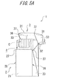
- FIG. 5A illustrates a state in which the lid 3 of the package 1 is opened. In this state, a user accesses the cigarettes which are the objects to be contained which are contained inside the outer box 2, and can freely extract the cigarettes.
- Fig. 5C illustrates a state in which the lid 3 in the package 1 is completely closed, that is, a state in which the package 1 is closed.
- Fig. 5B illustrates a state in which the lid 3 is substantially closed.
- the lock mechanism of the package 1 is a mechanism for restraining the closed lid 3 from being accidentally opened against an intention of the user, in order to improve lid closure of the package 1 (the lid 3).
- the lock mechanism of the package 1 is formed by a combination of the inclined surface locking edge 27 which is provided at the outer box 2 side, and the protruded claw 37 which engages with the inclined surface locking edge 27 and is provided at the lid 3 side.
- the protruded claw 37 is formed to protrude toward the lower side of the lid 3, from a lower end of the front side edge portion 36 which connects the front wall 31 and the side wall 33 in the lid 3.
- the inclined surface locking edge 27 is formed by diagonally cutting off the upper end of the front side edge portion 26 by which the front wall 21 and the side wall 22 of the outer box 2 are connected, and is constructed to be able to receive the protruded claw 37 which is provided at the lid 3 side when the lid 3 is closed.
- the protruded claws 37 are formed at both the front side edge portions 36 in the lid 3, that is, a pair of respective front side edge portions 36.
- the inclined surface locking edges 27 are formed at both of the front side edge portions 26 in the outer box 2, that is, a pair of the respective front side edge portions 26.
- the lock mechanism of the package 1 is constructed by the combinations of the protruded claws 37 and the inclined surface locking edges 27 which are formed to be engaged with one another at a left and a right of the package 1. Accordingly, the package 1 according to the present embodiment includes the two pairs of lock mechanisms in total at a left front side and a right front side of the package 1.
- Fig. 5C illustrates the state immediately before the lock mechanism of the package 1 operates, that is, immediately before the corresponding protruded claws 37 and inclined surface locking edges 27 are engaged with one another.
- the front side edge portions 26 which connect the front wall 21 and the respective side walls 23 of the outer box 2 are square edges having square shapes
- the front side edge portions 36 which connect the front wall 31 and the side walls 33 of the lid 3 are chamfered edges having chamfered shapes.
- a relative relation of the front side edge portion 26 and the front side edge portion 36 is specified so that the front side edge portion 36 of the lid 3 is disposed in the inner side in the cross sectional direction of the package 1, from the front side edge portion 26 of the outer box 2.
- the front side edge portion 36 at the lid 3 side is disposed at the inner side from the front side edge portion 26 of the outer box 2, and therefore, when an operation of closing the lid 3 is performed by relatively rotating the outer box 2 and the lid 3 with the hinge 5 which is formed at the back side of the package 1 as the center, a tip end side of the protruded claw 37 which protrudes from the lower end of the lid 3 engages with the inclined surface locking edge 27 which is provided at the outer box 2. More specifically, the protruded claw 37 collides with an outer surface side of the inclined surface locking edge 27.
- the protruded claw 37 rides over the inclined surface locking edge 27 from the outer surface side to an inner surface side of the inclined surface locking edge 27.
- the protruded claw 37 of the lid 3 is locked by the inclined surface locking edge 27 of the outer box 2, and the lid 3 is brought into the closed state.
- the protruded claw 37 of the lid 3 is locked by the inclined surface locking edge 27 of the outer box 2, whereby the rotational operation in the opening direction of the lid 3 is restricted as long as the protruded claw 37 of the lid 3 does not ride over the inclined surface locking edge 27 from the inner surface side to the outer surface side again.
- lid closing performance of the package 1 can be improved. Namely, the package 1 which is excellent in lid closing performance can be provided.
- the lock mechanism thereof is constructed by the combinations of the protruded claws 37 and the inclined surface locking edges 27 which are provided at the respective front side edge portions in the lid 3 and the outer box 2.
- the locking portions are not provided in sites near centers which have high utility value as display spaces for advertisement and the like which display advertisement/publicity and the other information relating to the product and the manufacturer of the front wall 21 and the side walls 23 in the outer box 2 side, the protruded region of the inner frame 4, and sites near to centers of the front wall 31 and the side walls 33 in the lid 3 side, and therefore, the display space for advertisement and the like of the package 1 can be sufficiently secured.
- the new and novel lock method which is not found in the prior art, like the lock mechanism which is constructed by the combinations of the protruded claws 37 which are provided at the front side edge portions 36 of the lid 3 and the inclined surface locking edges 27 which are provided at the front side edge portions 26 of the outer box 2, eagerness to buy of consumers can be aroused. As a result, the commercial value of the package 1, or the product containing the objects to be contained can be further enhanced. Further, according to the lock mechanism adopted by the package 1, the cutouts, the cut and raised pieces and the like which are to be the locking portions do not need to be formed in the inner frame as in the prior art, and therefore, reduction in strength and rigidity of the package 1 also can be avoided.
- the hinged-lid package excellent in lid closing performance without causing inconveniences such as insufficiency of a display space for advertisement and the like, and reduction in strength and rigidity of the package can be provided.
- the structure of the lock mechanism may be changed. That is to say, another mode may be adopted as the lock mechanism if the lock mechanism is constructed by the combinations of the locking portions and the locked portions which are provided at the respective front side edge portions in the lid 3 and the outer box 2, and the lock mechanism is not limited to the combinations of the protruded claws and the inclined surface locking edges which are described above.
- the locked portions at the lid 3 side do not always need to be provided at the lower ends of the front side edge portions 36
- the locking portions at the outer box 2 side do not always need to be provided at the upper ends of the front side edge portions 26, and the disposition positions may be changed as long as the disposition positions do not depart from the gist of the present invention.
- the front side edge portion 26 is made the square edge
- the front side edge portion 36 is made the chamfered edge so that the front side edge portion 36 of the lid 3 is disposed at the inner side of the package 1 from the front side edge portion 26 of the outer box 2, in the state in which the lid 3 is closed, but other shapes may be adopted as the shapes of the respective front side edge portions 26 and 36.
- the front side edge portion 26 at the outer box 2 side may be made a square edge
- the front side edge portion 36 at the lid 3 side may be made a round edge in a circular-arc shape.
- a combination of the shapes of the front side edge portion 26 at the outer box 2 side and the front side edge portion 36 at the lid 3 side is not limited to the above described illustration, and various shapes can be adopted.
- the package 100 is a hinged-lid package similarly to the package 1 according to the first embodiment.
- Figs. 6 to 9 are perspective views of the package 100 according to the second embodiment.
- Fig. 10 is a side view of the package 100 according to the second embodiment.
- Figs. 6 and 7 illustrate the package 100 in a closed state
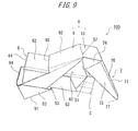
- Figs. 8 to 10 illustrate the package 100 in an opened state. Note that respective orientations of an up, a down, a front, a rear, a left and a right in the package 100 are as illustrated in Figs. 6 and 7 .
- the package 100 has an outer box 6 as a containing portion, a lid 7 as a lid portion that is connected to the outer box 6 rotatably via a first hinge 51, an outer tray 8 and the like.
- the outer box 6 is a box body in which an upper end side of a rectangular parallelepiped-shape is an open end.
- the outer box 6 has a front wall 61, a rear wall 62, a pair of side walls 63 and a bottom wall 64.
- the front wall 61 and the rear wall 62 are disposed to face each other, and both side edges of them are connected to one another by the pair of side walls 63.
- the bottom wall 64 is connected to lower ends of the front wall 61, the rear wall 62 and the side walls 63.
- the outer box 6 which is constructed as above has a diagonal open end 65 at an upper portion.
- An edge portion that is formed in a boundary position of the front wall 61 and the side wall 63 of the outer box 6, and an edge portion that is formed in a boundary position of the rear wall 62 and the side wall 63 have chamfered shapes, and form so-called chamfered edges.
- the first hinge 51 extends along the rear wall 62 of the outer box 6, and rotatably connects the lid 7 to the rear wall 62.
- the lid 7 is a lid member having a front wall 71, a rear wall 72, a pair of side walls 73 and a top wall 74.
- the lid 7 corresponds to a lid portion according to the present invention.
- the rear wall 72 of the lid 7 is disposed to face the front wall 71.
- the top wall 74 is connected to the front wall 71 and the rear wall 72 to be orthogonal to the front wall 71 and the rear wall 72.
- the lid 7 which is constructed as above is capable of relatively rotating to the outer box 6 with the first hinge 51 as a center, and opens and closes the open end 65 by being put on the open end 65 of the outer box 6.
- the lid 7 has front side edge portions 76 having chamfered shapes.
- the front side edge portions 76 form boundary portions of the front wall 71 and the respective side walls 73, and are edge portions that connect the front wall 71 and the side walls 73.
- the front side edge portion 76 is a so-called chamfered edge, and corresponds to a front side edge portion of the lid portion according to the present invention.
- protruded claws 77 that protrude downward are formed.
- the protruded claw 77 corresponds to a locked portion according to the present invention.
- the outer tray 8 is a cover member (an exterior member) that is provided at the rear wall 62 (the back) side of the outer box 6.
- the outer tray 8 is held to be in a posture along the respective rear wall surfaces 62 and 72 so as to cover both of the rear wall 62 of the outer box 6 and the rear wall 72 of the lid 7 when the lid 7 is in a closed state.
- the outer tray 8 is a member which plays a role of raising (setting up) the outer box 6, with the opening operation of the lid 3.
- the outer tray 8 corresponds to an outer member according to the present invention.
- the outer tray 8 has a first tray portion 9 and a second tray portion 10.
- the first tray portion 9 is joined (bonded) to the outer box 6, and the second tray portion 10 is joined (bonded) to the lid 7. Further, in a boundary position of the first tray portion 9 and the second tray portion 10, a second hinge 52 is formed, and the first tray portion 9 and the second tray portion 10 are rotatable relatively to each other with the second hinge 52 as a boundary.
- the first tray portion 9 of the outer tray 8 has a front wall 91, a rear wall 92, a pair of side walls 93 and a bottom wall 94.
- the front wall 91 and the rear wall 92 are disposed to face each other, and both side edges of them are connected to one another by the pair of side walls 93.
- the bottom wall 94 is connected to lower ends of the front wall 91, the rear wall 92 and the side walls 93.
- the bottom wall 94 of the first tray portion 9 has substantially the same shapes and sizes as the bottom wall 64 of the outer box 6, and in the state in which the lid 7 is closed, the bottom wall 64 in the outer box 6 and the rear wall 92 in the first tray portion 9 are laid on each other.
- the rear wall 92 of the first tray portion 9 has a substantially rectangular shape, and a height dimension thereof is substantially equal to a sum of a height dimension of the rear wall 62 in the outer box 6 and a height dimension of the rear wall 72 in the lid 7. Further, a width dimension of the rear wall 92 is slightly larger than a width dimension of the rear wall 62 in the outer box 6. Further, in a region of a substantially lower half in the rear wall 92, an opening portion 95 is formed. The opening portion 95 is formed throughout an entire width of the rear wall 92. Accordingly, an opening width of the opening portion 95 is substantially equal to or slightly larger than the width dimension of the rear wall 62 in the outer box 6. Note that an edge portion that is formed in a boundary position of the rear wall 92 and the side wall 93 in the first tray portion 9 has a chamfered shape, and is a so-called chamfered edge.
- the front wall 91 of the first tray portion 9 has a substantially rectangular shape, and a height dimension thereof is substantially equal to a dimension that is obtained by subtracting a height dimension of the front wall 71 in the lid 7 from a height dimension of the package 100. Namely, a sum of the height dimension of the front wall 91 in the first tray portion 9 and the height dimension of the front wall 71 in the lid 7 is substantially equal to the height dimension of the package 100. Further, a width dimension of the front wall 91 in the first tray portion 9 is substantially equal to a width dimension of the front wall 71 in the lid 7, and is slightly larger than a width dimension of the front wall 61 in the outer box 6.
- the front wall 91 of the first tray portion 9 is joined to the front wall 61 of the outer box 6 to be relatively rotatable, via a third hinge 53.
- the third hinge 53 is formed to extend along an upper end edge of the front wall 91 in the first tray portion 9.
- Respective front side edge portions 96 that are formed in boundary positions of the front wall 91 and the respective side walls 93 in the first tray portion 9 have square shapes.
- the front side edge portion 96 is a so-called square edge, and corresponds to an outer front side edge portion according to the present invention.
- inclined surface locking edges 97 that are formed by diagonally cutting off the upper end portions are formed.
- the inclined surface locking edge 97 corresponds to the locking portion according to the present invention
- the second tray portion 10 of the outer tray 8 has a substantially rectangular shape.
- the second tray portion 10 has a substantially same size as the top wall 74 of the lid 7, and in the state in which the lid 7 is closed, the second tray portion 10 of the outer tray 8 is laid on the top wall 74 of the lid 7.
- the second tray portion 10 is joined to a fourth hinge 54 that is formed at a front side edge portion of the top wall 74 in the lid 7, namely, an edge portion forming a boundary of the top wall 74 and the front wall 71 to be relatively rotatable.
- the first to the fourth hinges 51, 52, 53 and 54 are parallel with one another, and are formed along a width direction of the package 100.
- the package 100 is formed by folding and bonding respective parts of a third blank B3 forming the outer box 6 and a part of the lid 7, and a fourth blank B4 forming the outer tray 8 and a remaining part of the lid 7.
- Fig. 11 illustrates the third blank B3
- Fig. 12 illustrates the fourth blank B4.
- a paper material such as cardboard and manila board, or a resin such as a plastic sheet can be used, but the material of the blanks is not limited to these materials. Further, in explanation of the blanks, explanation will be made with the up and down direction in the drawings as a reference.
- the third blank B3 has an outer box zone R3 to be the outer box 6, and a first lid zone R4 to be a part of the lid 7.
- the outer box zone R3 has a front wall panel P21 to be the front wall 61 of the outer box 6, and side wall panels P22 and P22 to be the side walls 63 of the outer box 6 connect to both side edges of the front wall panel P21.
- a bottom wall panel P23 to be the bottom wall 64 of the outer box 6 connects to an upper edge (an upper edge in Fig. 11 ) of the front wall panel P21.
- a rear wall panel P24 that is located at a side opposite from the front wall panel P21 to be the rear wall 62 of the outer box 6 connects to the bottom wall panel P23.
- Inner side panels P25 and P25 facing the side wall panels P22 connect to both side edges of the rear wall panel P24.
- inner bottom flaps P26 connect to lower edges of the respective inner side panels P25, and the inner bottom flaps P26 are laid on the bottom wall panel P23, and reinforce the bottom wall 64 of the outer box 6.
- the first lid zone R4 has a rear wall panel P27 to be the rear wall 71 of the lid 7, and a lower edge of the rear wall panel P27 is connected to the rear wall panel P24 in the outer box zone R3 via a folding line and a slit S2. Further, a top wall panel P28 to be the top wall 74 of the lid 7 connects to an upper edge of the rear wall panel P27 in the first lid zone R4. Further, inner side flaps P29 to be parts of the side walls 73 of the lid 7 respectively connect to both side edges of the rear wall panel P27. Inner top flaps P30 connect to upper edges of the respective inner side flaps P29, and the inner top flaps P30 are laid on the top wall panel P28 and reinforce the top wall 74 in the lid 7.
- the fourth blank B4 has a second lid zone R5 to be a remaining part of the lid 7, and an outer tray zone R6 to be the outer tray 8.
- the second lid zone R5 has a front wall panel P31 to be the front wall 71 of the lid 3, and an inner front flap P32 that reinforces the front wall panel P31 connects to an upper edge of the front wall panel P31.
- side panels P33 to be the side walls 73 of the lid 7 respectively connect to both side edges of the front wall panel P31.
- protruded portions that protrude upward are formed in boundary portions of the front wall panel P31 and the side wall panels P33 which connect to the front wall panel P31, and by the protruded portions, the protruded claws 77 of the lid 7 are formed.
- a top panel P34 to be the second tray portion 10 of the outer tray 8 connects to the front wall panel P31 in the second lid zone R5.
- a rear wall panel P35 to be the rear wall 92 in the first tray portion 9 connects to a lower edge of the top panel P34.
- side wall panels P36 to be the side walls 93 in the first tray portion 9 respectively connect to both side edges of the rear wall panel P35.
- a bottom wall panel P37 to be the bottom wall 94 in the first tray portion 9 connects to a lower edge in one of the side wall panels P36.
- a first reinforcement side panel P38 that reinforces the side wall 93 of the first tray portion 9 by being laid on the other side wall panel P36 connects to a lower edge of the bottom wall panel P37.
- a front wall panel P39 to be the front wall 91 in the first tray portion 9 connects to a right edge of the bottom wall panel P37.
- a second reinforcement side panel P40 that reinforces the side wall 93 of the first tray portion 9 by being laid on one of the side wall panels P36 connects to an upper edge of the front wall panel P39.
- a third reinforcement side panel P41 that reinforces the side wall 93 of the first tray portion 9 by being laid on the other side wall panel P36 connects to a lower edge of the front wall panel P39.
- a junction panel P42 that is bonded to the front wall panel P21 of the outer box zone R3 in the third blank B3 connects to a right edge of the front wall panel P39.
- the third blank B3 and the fourth blank B4 which are described above are folded at folding lines illustrated by the broken lines in Figs. 11 and 12 .
- the package 100 including the outer box 6, the lid 7 and the outer tray 8 as illustrated in Figs. 6 to 10 is formed.
- the inner bottom flaps P26 are laid on the bottom wall panel P23 and the inner side flaps P25 are laid on the side wall panels P22 to be bonded, whereby the outer box 6 is formed.
- the chamfered edges which connect the front wall 61 and the side walls 63 of the outer box 6 are formed.
- the chamfered edges which connect the rear wall 62 and the side walls 63 of the outer box 6 are formed.
- the inner top flaps P30 are laid on the top wall panel P28, and the inner side flaps P29 are laid on the side wall panels P33 to be bonded, whereby the lid 7 is formed.
- the inner front flap P32 may be bonded to the front wall panel P31, or does not have to be bonded.
- the chamfered edges that connect the front wall 71 and the side walls 73 of the lid 7 are formed.
- the second reinforcement side panel P40 is bonded to the one side wall panel P36, and the first reinforcement side panel P38 and the third reinforcement side panel P41 are bonded to the other side wall panel P36.
- the junction panel P42 is bonded to the front wall panel P21 of the third blank B3, whereby the outer tray 8 is formed. Note that by double folding lines in boundary positions of the rear wall panel P35 and the side wall panels P36 in the outer tray zone R6, the chamfered edges which connect the rear wall 92 and the side walls 93 in the first tray portion 9 are formed.
- first hinge 51 of the package 100 is formed by the folding line and the slit S2 which form a boundary of the rear wall panel P24 in the outer box zone R3, and the rear wall panel P27 in the first lid zone R4.
- second hinge 52 of the package 100 is formed by a folding line that forms a boundary of the rear wall panel P35 and the top panel P34 in the outer tray zone R6.
- third hinge 53 of the package 100 is formed by a folding line that forms a boundary of the junction panel P42 and the front wall panel P39 in the outer tray zone R6.
- fourth hinge 54 of the package 100 is formed by a folding line that forms a boundary of the front wall panel P31 in the second lid zone R5 and the top panel P34 in the outer tray zone R6.
- a depth dimension of the bottom wall 94 is equal to a depth dimension of the bottom wall 64 in the outer box 6, and a height dimension of the rear wall 92 is equal to a sum of a height dimension of the rear wall 62 of the outer box 6 and a height dimension of the rear wall 72 of the lid 7.
- a depth dimension of the second tray portion 10 is equal to a depth dimension of the top wall 74 in the lid 7. Therefore, as illustrated in Figs.
- the first tray portion 9 of the outer tray 8 can be disposed along an outer surface of the outer box 6 without interfering with the outer box 6. Further, the second tray portion 10 of the outer tray 8 can be disposed along the top wall 74 of the lid 7. Thereby, a whole of the package 100 can be restrained from being bulky when the lid 7 of the package 100 is closed.
- the package 100 is assumed to be placed on a horizontal surface such as a table, for convenience.
- an operator performs an opening operation of the lid 7 by grasping both of the side walls 93 in the first tray portion 9 of the outer tray 8 with one hand, picking the lid 7 with the other hand, and the like. Namely, the lid 7 is rotated with respect to the outer box 6 with the first hinge 51 as a center.
- the first tray portion 9 is rotatably joined to the outer box 6 of the package 100 via the third hinge 53. Further, the second tray portion 10 is rotatably joined to the lid 7 via the fourth hinge 54. Furthermore, the first tray portion 9 and the second tray portion 10 are rotatably connected via the second hinge 52. Accordingly, when the opening operation of the lid 7 is performed, in an interlocking manner with the opening operation, the first tray portion 9 and the second tray portion 10 rotate with the second hinge 52 as the center, the first tray portion 9 rotates with respect to the outer box 6 with the third hinge 53 as the center, and the second tray portion 10 rotates with respect to the lid 7 with the fourth hinge 54 as the center.
- the second tray portion 10 which is laid on the top wall 74 of the lid 7 separates from the top plate 74, and the rear wall 92 of the first tray portion 9 which is laid on the rear wall 62 of the outer box 6 separates from the rear wall 62 of the outer box 6.
- the first tray portion 9 can be relatively rotated with respect to the outer box 6 with the third hinge 53 as the center without interfering with the rear wall 62 of the outer box 6, because in the rear wall 92 of the first tray portion 9, the opening portion 95 having an opening width which is equal to or slightly larger than the width dimension of the rear wall 62 of the outer box 6 is formed.
- the outer box 6 operates to rise from the outer tray 8 while the lid 7 is opened, as illustrated in Figs. 8 to 10 .
- the outer tray 8 is included, and therefore, the outer box 6 can be automatically raised from the outer tray 8 in the interlocking manner with the opening operation of the lid 7. Thereby, the operator can easily extract the cigarettes contained inside the package 100. Further, the rising operation of the outer box 6 which is in the interlocking manner with the opening action of the lid 7 as described above is a new action which is not found in the prior art. By adopting the new opening and closing method like this, the package 100 can stimulate the eagerness to buy of consumers, and can enhance the commercial value of the product including the package 100.
- the package 100 includes the lock mechanism for realizing favorable lid closure similarly to the package 1 according to the first embodiment.
- the lock mechanism is constructed by the protruded claws 77 which are provided at the lid 7, and the inclined surface locking edges 97 which are provided at the first tray portion 9 of the outer tray 8 and are engaged with the protruded claws 77.
- the protruded claws 77 are formed at both of the respective front side edge portions 76 in the lid 7, that is, a pair of the front side edge portions 76.
- the inclined surface locking edges 97 are formed at both of the respective front side edge portions 96 in the first tray portion 9, that is, a pair of front side edge portions 96.
- the package 100 includes two pairs of lock mechanisms in total at the left front side and the right front side of the package 100.
- the front side edge portion 96 of the first tray portion 9 in which the inclined surface locking edge 97 is formed at the upper end is made a square edge
- the front side edge portion 76 of the lid 7 in which the protruded claw 77 is formed at the lower end is made a chamfered edge. Therefore, in the state in which the lid 7 is closed, the front side edge portion 76 at the lid 7 side is brought into a state disposed at the inner side in the cross sectional direction of the package 100, as compared with the front side edge portion 96 of the first tray portion 9.
- the relative relation of the front side edge portion 96 and the front side edge portion 76 is specified so that the front side edge portion 76 of the lid 7 is disposed at an inner side in the cross sectional direction of the package 100 from the front side edge portion 96 of the first tray portion 9, in the state in which the lid 7 is closed.
- the protruded claw 77 provided at the lid 7 side is received and locked by the inclined surface locking edge 97 which is provided at the outer tray 8 side, when the lid 7 is closed.
- the protruded claw 77 of the lid 7 collides with an outer surface side of the inclined surface locking edge 97 of the outer tray 8.
- the protruded claw 77 of the lid 7 rides over the inclined surface locking edge 97 to the inner surface side from the outer surface side of the inclined surface locking edge 97.
- the protruded claw 77 of the lid 7 is locked by the inclined surface locking edge 97, and the lid 7 is locked to the closed state. Thereby, the lid 7 is restrained from being accidentally opened. Thereby, lid closing performance of the package 100 can be improved.
Landscapes
- Engineering & Computer Science (AREA)
- Mechanical Engineering (AREA)
- Cartons (AREA)
- Packaging Of Annular Or Rod-Shaped Articles, Wearing Apparel, Cassettes, Or The Like (AREA)
- Closures For Containers (AREA)
Abstract
Description
- The present invention relates to a hinged-lid package.
- As a package that contains an object to be contained such as a tobacco product, there have been conventionally known soft pack type packages, hard packages and the like. As one form of the hard packages, there is known a hinged-lid package including a lid portion (lid). In each of the hinged-lid packages of this kind, a containing portion that has a box-shaped outer shape and contains an object to be contained, and a lid portion for opening and closing an open end that is formed at an upper portion of the containing portion are generally connected rotatably via a hinge that is provided along an edge portion of the open end.
- A hinged-lid package adopts a mechanism that connects the containing portion and the lid portion rotatably via a hinge, and therefore, has a problem that the lid portion is easily opened accidentally. In regard to this, a hinged-lid package including a locking mechanism (hereinafter, also called "a lock mechanism") at the lid portion, which prevents accidental opening of the lid portion, is also proposed (See
Patent document 1 or the like, for example.). - Many of the lock mechanisms of the lid portions as above are each formed by a combination of a locking portion formed of a cutout that is formed in an inner frame, a cut and raised piece that is formed by cutting and raising a part of the inner frame and the like, and a locked piece that is provided on an inner surface side of the lid portion so as to be locked to the locking portion when the lid portion is closed.
- Patent document 1: Japanese Patent No.
3559153 - Incidentally, while an inner frame generally protrudes upward from the open end of a containing portion, the protruding region is sometimes used as a display space (hereinafter, called "a display space for advertisement or the like") where advertisement/publicity and the other information relating to a product and a manufacturer. However, when a locking portion is formed in the protruding region of the inner frame as in the conventional lid locking mechanism, there arises the fear of the display space for advertisement and the like being unable to be secured sufficiently. Further, as the inner frame is a member for reinforcing the containing portion of the package, there arises the fear that the strength and rigidity of the inner frame are reduced by forming cutouts, and cut and raised pieces.
- The present invention is made in the light of the problem as above, and has an object to provide a hinged-lid package excellent in lid closing performance without causing inconveniences such as insufficiency of a display space for advertisement or the like, reduction in strength and rigidity of a package and the like.
- In order to solve the above described problem, in a hinged-lid package according to the present invention, a locked portion is formed at an edge portion side that connects a front wall and a side wall of a lid portion, and a locking portion capable of locking the locked portion when the lid portion is closed is provided at a containing portion side.
- In more detail, a hinged-lid package according to the present invention includes a box-shaped containing portion that has an open end at an upper portion, and is capable of containing an object to be contained inside, a lid portion that is rotatably connected to a rear side open edge of the open end via a hinge, and is put on the open end to open and close the open end, a locked portion that is formed at a front side edge portion at a lid portion side that connects a front wall and a side wall of the lid portion, and a locking portion that is provided at the containing portion side, and locks the locked portion when the lid portion is closed.
- According to the above described structure, the locked portion which is formed at the lid portion side is locked by the locking portion which is formed at the containing portion side when the lid portion is closed, whereby the hinged-lid package can be restrained from being accidentally opened. In the present invention, the locked portion is formed at the front side edge portion of the lid portion, and the locking portion is provided at a site at the containing portion side which engages with the locked portion when the lid portion is closed, and therefore, the hinged-lid package excellent in lid closing performance while sufficiently ensuring a display space for advertisement and the like which displays advertisement/publicity and other information concerning the product and the manufacturer can be provided. Further, according to the present invention, there is no need to form cutouts, cut and raised pieces and the like to be the locking portion in the inner frame, and therefore, reduction in strength and rigidity of the package can be restrained. Note that the locking portion in the present invention may be formed at a wall surface which forms the containing portion, or may be formed on a wall surface of a fitting member which is fitted to the containing portion. The latter mode is also included in the concept that "the locking portion is provided at the containing portion side".
- Further, in the hinged-lid package according to the present invention, the locked portion may be a protruded claw that is protruded downward from a lower end of the front side edge portion of the lid portion. Further, the locking portion may be an inclined surface locking edge that is formed by diagonally cutting off an upper end of a front side edge portion at the containing portion side that connects a front wall and a side wall of the containing portion. In this case, the front side edge portion at the lid portion side is disposed at an inner side in a cross sectional direction of the package as compared with the front side edge portion at the containing portion side, and the inclined surface locking edge may be constructed to lock the locked portion which rides over the inclined surface locking edge to an inner surface side from an outer surface side when the lid portion is closed. Further, the front side edge portion at the lid portion side where the locked portion is formed may have a chamfered shape or a circular-arc shape, and the front side edge portion at the containing portion side where the locking portion is formed may be constructed to have a square shape.
- Further, in the hinged-lid package according to the present invention, the locking portion may be an inclined surface locking edge that is formed by diagonally cutting off an upper end of an outer front side edge portion that connects a front wall and a side wall of an outer member that is fitted to an outer side of the containing portion. In this case, the front side edge portion at the lid portion side may be disposed at an inner side in a cross sectional direction of the package as compared with the outer front side edge portion of the lid portion, and the inclined surface locking edge may be constructed to lock the locked portion which rides over the inclined surface locking edge to an inner surface side from an outer surface side when the lid portion is closed. Further, the front side edge portion at the lid portion side where the locked portion is formed may have a chamfered shape or a circular-arc shape, and the outer front side edge portion where the locking portion is formed may have a square shape. The front side edge portion at the lid portion side where the locked portion is formed may be constructed to have a chamfered shape or a circular-arc shape, and the outer front side edge portion where the locking portion is formed may be constructed to have a square shape.
- Further, in the hinged-lid package according to the present invention, the locked portions may be formed at both of front side edge portions in the lid portion. Further, the locking portions may be formed at both of front side edge portions in the containing portion, or the outer member.
- Note that the objects to be contained which are contained in the hinged-lid package according to the present invention are not specially limited, but tobacco products, for example, can be preferably illustrated as the objects to be contained. As the tobacco products, for example, cigarettes (filter cigarettes, plain cigarettes (without filters)), cigars (rolls of tobacco leaves), cigarillos, snus, snuff, chewing tobacco, electronic cigarettes and the like can be illustrated. Further, the hard package according to the present invention may be a package that contains sweets, chewing gum and the like, for example.
- Further, the means for solving the problem in the present invention can be adopted by being combined wherever possible.
- According to the present invention, the hinged-lid package excellent in lid closing performance without causing inconveniences such as insufficiency of a display space for advertisement and the like and reduction in strength and rigidity of the package can be provided.
-
- [
Fig. 1] Fig. 1 is a perspective view of a package according to a first embodiment. - [
Fig. 2] Fig. 2 is a perspective view of the package according to the first embodiment. - [
Fig. 3] Fig. 3 is a view illustrating a first blank according to the first embodiment. - [
Fig. 4] Fig. 4 is a view illustrating a second blank according to the first embodiment. - [
Fig. 5A] Fig. 5A is a view explaining an opening and closing operation of the package according to the first embodiment. - [
Fig. 5B] Fig. 5B is a view explaining the opening and closing operation of the package according to the first embodiment. - [
Fig. 5C] Fig. 5C is a view explaining the opening and closing operation of the package according to the first embodiment. - [
Fig. 6] Fig. 6 is a perspective view of a package according to a second embodiment. - [
Fig. 7] Fig. 7 is a perspective view of the package according to the second embodiment. - [
Fig. 8] Fig. 8 is a perspective view of the package according to the second embodiment. - [
Fig. 9] Fig. 9 is a perspective view of the package according to the second embodiment. - [
Fig. 10] Fig. 10 is a side view of the package according to the second embodiment. - [
Fig. 11] Fig. 11 is a view illustrating a third blank according to the second embodiment. - [
Fig. 12] Fig. 12 is a view illustrating a fourth blank according to the second embodiment. - Here, embodiments of a hinged-lid package according to the present invention will be described based on the drawings. An object to be contained that is contained in the package to which the present invention is applied is not limited to a specific object, and here, a case of containing cigarettes in the package will be described as an example.
-
Figs. 1 and2 are perspective views of a hinged-lid package (hereinafter, simply called "a package") 1 according to a first embodiment.Figs. 1 and2 are perspective views of thepackage 1 seen from a diagonally front side of a frontage. Thepackage 1 is a box-shaped package with a hinge lid that forms a substantially rectangular parallelepiped-shape as a whole. Thepackage 1 includes anouter box 2 as a containing portion, alid 3 as a lid portion that is connected to theouter box 2 rotatably via ahinge 5, and aninner frame 4 that is fitted to theouter box 2. Hereinafter, in the present description, a frontage side of thepackage 1 is defined as "a front side", and a back side is defined as "a rear side" except for a case specially mentioned. Further, a lid side of thepackage 1 is defined as "an upper side", and an opposite side (a bottom side of the package) is defined as "a lower side". As a material that is used for thepackage 1, a paper material such as cardboard, and manila board is preferably used, but the material of thepackage 1 is not limited to this. For example, as the material of thepackage 1, not only a resin material such as a plastic but also other materials can be properly used. In the case of using a paper material for the material of thepackage 1, a paper material with a basic weight of 100 g/m2 or more and 400 g/m2 or less, for example, may be used. - The
outer box 2 is a box body having a shape in which an upper end side of a rectangular parallelepiped-shape is diagonally cut out. Theouter box 2 has afront wall 21, arear wall 22, a pair ofside walls 23 and abottom wall 24. Thefront wall 21 forms a substantially rectangular shape, therear wall 22 forms a rectangular shape, and thefront wall 21 and therear wall 22 are disposed to face each other. In more detail, thefront wall 21 has a hexagonal shape in which upper corner portions of a rectangular shape are diagonally cut off. Further, therear wall 22 has a height dimension longer than thefront wall 21. Theside walls 23 connect both side edges of thefront wall 21 and therear wall 22 to one another. Thebottom wall 24 is connected to lower ends of thefront wall 21, therear wall 22 and theside walls 23, and has a rectangular shape. An upper end edge 23a of theside wall 23 connects an upper end of thefront wall 21 and an upper end of therear wall 22. Theouter box 2 has a diagonalopen end 25 at an upper portion. - The
outer box 2 has a frontside edge portion 26 having a square (a right angle) shape. The frontside edge portions 26 form boundary portions of thefront wall 21 and therespective side walls 23, and are edge portions that connect thefront wall 21 and theside walls 23. The frontside edge portion 26 is a so-called square edge, and corresponds to a front side edge portion at a containing portion side according to the present invention. Further, at upper ends of the respective frontside edge portions 26, inclinedsurface locking edges 27 that are formed by diagonally cutting off upper end portions of the respective frontside edge portions 26 are formed. In the present embodiment, the inclinedsurface locking edge 27 corresponds to a locking portion according to the present invention. - Further, the
hinge 5 is provided at a rear side opening edge of theouter box 2, namely, an upper end of therear wall 22. Thehinge 5 extends along therear wall 22 of theouter box 2, and rotatably connects thelid 3 to therear wall 22. Note that for the purpose of improving the beauty, feel or the like, embossing, flock finishing by using staple pile (flock), pseudo embossing by applying varnish (varnishing) thickly or the like may be properly applied to an outer surface of theouter box 2. - The
lid 3 is a box-shaped lid member having afront wall 31, arear wall 32, a pair ofside walls 33 and atop wall 34. In the present embodiment, thelid 3 corresponds to a lid portion according to the present invention. In thelid 3, thefront wall 31 and thetop wall 34 have substantially rectangular shapes, and therear wall 32 has a rectangular shape. Therear wall 32 of thelid 3 is connected to therear wall 22 of theouter box 2 via thehinge 5, and is disposed to face thefront wall 31. Further, thetop wall 34 is connected to therear wall 32 to be orthogonal to therear wall 32. Further, the pair ofside walls 33 connect therear wall 32, thetop wall 34 and thefront wall 31, and have substantially trapezoidal shapes. Thelid 3 which is formed as above is capable of rotating with respect to theouter box 2 with thehinge 5 as a center, and opens and closes theopen end 25 by being put on theopen end 25 of theouter box 2. Note that when thelid 3 is closed, lower end edges of theside walls 33 of thelid 3 coincide with the upper end edges of theside walls 23 in theouter box 2. - The
lid 3 has frontside edge portions 36 each having a chamfered shape. The frontside edge portions 36 form boundary portions of thefront wall 31 and therespective side walls 33, and are edge portions that connect thefront wall 31 and theside walls 33. The frontside edge portion 36 is a so-called chamfered edge, and corresponds to a front side edge portion of the lid portion according to the present invention. At lower ends of the respective frontside edge portions 36, protrudedclaws 37 that protrude downward are formed. In the present embodiment, the protrudedclaw 37 corresponds to a locked portion according to the present invention. - The
inner frame 4 has afront surface frame 41 that forms a substantially U-shape, and a pair of side surface frames 42 that are connected to both side edges of thefront surface frame 41. Further, in theinner frame 4, anedge portion 43 that connects thefront surface frame 41 and theside surface frame 42 is in a so-called chamfered shape. A width (a chamfered width) of the edge portion (hereinafter, called "the front side edge portion") 43 in theinner frame 4, and a width (a chamfered width) of the frontside edge portion 36 in thelid 3 are substantially equal, and thelid 3 and theinner frame 4 do not interfere with each other when thelid 3 is closed. Further, theinner frame 4 is bonded to an inner surface of theouter box 2 in a state in which theinner frame 4 is partially protruded upward from theopen end 25 of the upper portion of theouter box 2. In the present embodiment, thefront surface frame 41 is bonded to thefront wall 21 in a lap region in which thefront surface frame 41 and thefront wall 21 of theouter box 2 are laid on each other, but a method and a mode of fixing theinner frame 4 to theouter box 2 are not limited to this. - The
inner frame 4 reinforces theopen end 25 of theouter box 2, and also functions as a guide member that guides opening and closing of thelid 3. As is obvious fromFig. 2 , thefront surface frame 41 has a substantially rectangular cutoutconcave portion 41a. The cutoutconcave portion 41a widely opens a front surface of theinner frame 4, and facilitates extraction of cigarettes. - In the present embodiment, the
package 1 is formed by folding and bonding respective parts of a first blank B1 for forming theouter box 2 and thelid 3, and a second blank B2 for forming theinner frame 4.Fig. 3 illustrates the first blank B1, andFig. 4 illustrates the second blank B2. For the first blank B1 and the second blank B2, a paper material such as cardboard and manila board, or a resin such as a plastic sheet can be used, but the material is not limited to them. Further, in explanation of the blanks, explanation is made with the up and down directions in the drawings as a reference. - As illustrated in
Fig. 3 , the first blank B1 has an outer box zone R1 to be theouter box 2, and a lid zone R2 to be thelid 3. The outer box zone R1 has a front wall panel P1 to be thefront wall 21 of theouter box 2, and side wall panels P2 and P2 to be theside walls 23 of theouter box 2 connect to both side edges of the front wall panel P1. - Further, a bottom wall panel P3 to be the
bottom wall 24 of theouter box 2 connects to an upper edge (an upper edge inFig. 4 ) of the front wall panel P1. A rear wall panel P4 that is located at a side opposite from the front wall panel P1 to be therear wall 22 of theouter box 2 connects to the bottom wall panel P3. Inner side panels P5 and P5 that face the side wall panels P2 connect to both side edges of the rear wall panel P4. Further, inner bottom flaps P6 connect to lower edges of the respective inner side panels P5, and the inner bottom flaps P6 are laid on the bottom wall panel P3 and reinforce thebottom wall 24 of theouter box 2. - The lid zone R2 has a rear wall panel P7 to be the
rear wall 31 of thelid 3, and a lower edge of the rear wall panel P7 is connected to the rear wall panel P4 in the outer box zone R1 via a folding line and a slit S1. Further, a top wall panel P8 to be thetop wall 34 of thelid 3 connects to an upper edge of the rear wall panel P7 in the lid zone R2. Further, inner side flaps P9 to be parts of theside walls 33 of thelid 3 respectively connect to both side edges of the rear wall panel P7. Inner top flaps P10 connect to upper edges of the respective inner side flaps P9, and these inner top flaps P10 are laid on the top wall panel P8 to reinforce thetop wall 34. - Further, a front wall panel P11 that is located at a side opposite from the rear wall panel P7 to be the
front wall 31 of thelid 3 connects to an upper edge of the top wall panel P8. An inner font flap P12 further connects to an upper edge of the front wall panel P11. The inner front flap P12 is folded inside and is laid on the front wall panel P11, and thereby reinforces thefront wall 31 of thelid 3. Further, side wall panels P14 to be theside walls 33 of thelid 3 respectively connect to both side edges of the front wall panel P11 via edge portion panels P13 to be the frontside edge portions 36 of thelid 3. The aforementioned inner side flaps P9 are laid on the side wall panels P14 and are bonded, and thereby reinforce theside walls 34. Further, a protruded portion is formed on upper end sides of the edge portion panel P13 and the side wall panel P14 in such a manner as to be astride the edge portion panel P13 and the side wall panel P14, and the protrudedclaw 37 of thelid 3 is formed by the protruded portion. - As illustrated in
Fig. 4 , the second blank B2 has a front surface panel P15 to be thefront surface frame 41 of theinner frame 4, and side surface panels P17 to be the side surface frames 42 connect to both side edges of the front panel P15 via edge portion panels P16 to be the frontside edge portions 43 of theinner frame 4. - The first blank B1 and the second blank B2 which are described above are respectively folded along folding lines illustrated by broken lines in
Figs. 3 and 4 . As a result, thepackage 1 including theouter box 2, thelid 3 and theinner frame 4 as illustrated inFig. 1 andFig. 2 is formed. In more detail, in the outer box zone R1 of the first blank B1, folding is performed along the respective folding lines, the inner bottom flaps P6 are laid on the bottom wall panel P3, and the inner side flaps P5 are laid on and bonded to the side wall panels P2, whereby theouter box 2 is formed. Subsequently, the front surface panel P15 of the second blank B2 is bonded to the front wall panel P1 of the outer box zone R1, whereby theouter box 2 and theinner frame 4 are integrated. - Meanwhile, in the lid zone R2 of the first blank B1, folding is performed along the respective folding lines, the inner top flap P10 is laid on the top wall panel P8, and the inner side flaps P9 are laid on and bonded to the side wall panels P14, whereby the
lid 3 is formed. Note that in the present embodiment, the inner front flap P12 in the lid zone R2 is not bonded to the front wall panel P11, but may be bonded to the front wall panel P11. - Referring to
Figs. 5A to 5C , an opening and closing operation of thepackage 1 and a lock mechanism included by thepackage 1 will be described. InFigs. 5A to C , reference numerals and symbols common to those inFigs. 1 an 2 indicate the same members.Fig. 5A illustrates a state in which thelid 3 of thepackage 1 is opened. In this state, a user accesses the cigarettes which are the objects to be contained which are contained inside theouter box 2, and can freely extract the cigarettes.Fig. 5C illustrates a state in which thelid 3 in thepackage 1 is completely closed, that is, a state in which thepackage 1 is closed.Fig. 5B illustrates a state in which thelid 3 is substantially closed. - The lock mechanism of the
package 1 is a mechanism for restraining theclosed lid 3 from being accidentally opened against an intention of the user, in order to improve lid closure of the package 1 (the lid 3). In the present embodiment, the lock mechanism of thepackage 1 is formed by a combination of the inclinedsurface locking edge 27 which is provided at theouter box 2 side, and the protrudedclaw 37 which engages with the inclinedsurface locking edge 27 and is provided at thelid 3 side. Note that as described above, the protrudedclaw 37 is formed to protrude toward the lower side of thelid 3, from a lower end of the frontside edge portion 36 which connects thefront wall 31 and theside wall 33 in thelid 3. Further, the inclinedsurface locking edge 27 is formed by diagonally cutting off the upper end of the frontside edge portion 26 by which thefront wall 21 and theside wall 22 of theouter box 2 are connected, and is constructed to be able to receive the protrudedclaw 37 which is provided at thelid 3 side when thelid 3 is closed. - Further, as illustrated in
Figs. 1 ,2 and5A to C , the protrudedclaws 37 are formed at both the frontside edge portions 36 in thelid 3, that is, a pair of respective frontside edge portions 36. Further, the inclinedsurface locking edges 27 are formed at both of the frontside edge portions 26 in theouter box 2, that is, a pair of the respective frontside edge portions 26. The lock mechanism of thepackage 1 is constructed by the combinations of the protrudedclaws 37 and the inclinedsurface locking edges 27 which are formed to be engaged with one another at a left and a right of thepackage 1. Accordingly, thepackage 1 according to the present embodiment includes the two pairs of lock mechanisms in total at a left front side and a right front side of thepackage 1. - Next, an operation at a time of opening and closing the
package 1 will be explained based on the drawings. First, when thelid 3 of thepackage 1 is closed, thepackage 1 sequentially shifts to the state illustrated inFig. 5C via the states illustrated inFigs. 5A and5B. Fig. 5B illustrates the state immediately before the lock mechanism of thepackage 1 operates, that is, immediately before the corresponding protrudedclaws 37 and inclinedsurface locking edges 27 are engaged with one another. - As described above, in the
package 1, the frontside edge portions 26 which connect thefront wall 21 and therespective side walls 23 of theouter box 2 are square edges having square shapes, and the frontside edge portions 36 which connect thefront wall 31 and theside walls 33 of thelid 3 are chamfered edges having chamfered shapes. As a result, in the state in which thelid 3 is closed, the frontside edge portion 36 at thelid 3 side is disposed at an inner side in a cross sectional direction of thepackage 1 as compared with the frontside edge portion 26 of theouter box 2. In other words, a relative relation of the frontside edge portion 26 and the frontside edge portion 36 is specified so that the frontside edge portion 36 of thelid 3 is disposed in the inner side in the cross sectional direction of thepackage 1, from the frontside edge portion 26 of theouter box 2. - As described above, in the
package 1, in the cross sectional direction, the frontside edge portion 36 at thelid 3 side is disposed at the inner side from the frontside edge portion 26 of theouter box 2, and therefore, when an operation of closing thelid 3 is performed by relatively rotating theouter box 2 and thelid 3 with thehinge 5 which is formed at the back side of thepackage 1 as the center, a tip end side of the protrudedclaw 37 which protrudes from the lower end of thelid 3 engages with the inclinedsurface locking edge 27 which is provided at theouter box 2. More specifically, the protrudedclaw 37 collides with an outer surface side of the inclinedsurface locking edge 27. Subsequently, when thelid 3 is further operated to rotate in a closing direction, the protrudedclaw 37 rides over the inclinedsurface locking edge 27 from the outer surface side to an inner surface side of the inclinedsurface locking edge 27. Thereby, as illustrated inFig. 5C , the protrudedclaw 37 of thelid 3 is locked by the inclinedsurface locking edge 27 of theouter box 2, and thelid 3 is brought into the closed state. - As above, when the
lid 3 is closed, the protrudedclaw 37 of thelid 3 is locked by the inclinedsurface locking edge 27 of theouter box 2, whereby the rotational operation in the opening direction of thelid 3 is restricted as long as theprotruded claw 37 of thelid 3 does not ride over the inclinedsurface locking edge 27 from the inner surface side to the outer surface side again. Thereby, an accidental opening operation of thelid 3 which is not intended by a user can be prevented, and lid closing performance of thepackage 1 can be improved. Namely, thepackage 1 which is excellent in lid closing performance can be provided. - Note that when a force is applied in the opening direction of the
lid 3 to open thepackage 1 by the intention of the user, from the state illustrated inFig. 5C , the protrudedclaw 37 of thelid 3 rides over the inclinedsurface locking edge 27 from the inner surface side to the outer surface side, whereby lock of thelid 3 by the inclinedsurface locking edge 27 is released. Thereby, thelid 3 can be freely rotated in the opening direction, and the user can open thelid 3. - As above, according to the
package 1 according to the present embodiment, excellent lid closing performance is included, and the lock mechanism thereof is constructed by the combinations of the protrudedclaws 37 and the inclinedsurface locking edges 27 which are provided at the respective front side edge portions in thelid 3 and theouter box 2. According to the above, the locking portions are not provided in sites near centers which have high utility value as display spaces for advertisement and the like which display advertisement/publicity and the other information relating to the product and the manufacturer of thefront wall 21 and theside walls 23 in theouter box 2 side, the protruded region of theinner frame 4, and sites near to centers of thefront wall 31 and theside walls 33 in thelid 3 side, and therefore, the display space for advertisement and the like of thepackage 1 can be sufficiently secured. - Further, by adopting the new and novel lock method which is not found in the prior art, like the lock mechanism which is constructed by the combinations of the protruded
claws 37 which are provided at the frontside edge portions 36 of thelid 3 and the inclinedsurface locking edges 27 which are provided at the frontside edge portions 26 of theouter box 2, eagerness to buy of consumers can be aroused. As a result, the commercial value of thepackage 1, or the product containing the objects to be contained can be further enhanced. Further, according to the lock mechanism adopted by thepackage 1, the cutouts, the cut and raised pieces and the like which are to be the locking portions do not need to be formed in the inner frame as in the prior art, and therefore, reduction in strength and rigidity of thepackage 1 also can be avoided. - As above, according to the
package 1 according to the present embodiment, the hinged-lid package excellent in lid closing performance without causing inconveniences such as insufficiency of a display space for advertisement and the like, and reduction in strength and rigidity of the package can be provided. - The preferred embodiment of the present invention is described as above, and proper changes can be added to the above described embodiment within the range without departing from the gist of the present invention. For example, as a modification of the
package 1, the structure of the lock mechanism may be changed. That is to say, another mode may be adopted as the lock mechanism if the lock mechanism is constructed by the combinations of the locking portions and the locked portions which are provided at the respective front side edge portions in thelid 3 and theouter box 2, and the lock mechanism is not limited to the combinations of the protruded claws and the inclined surface locking edges which are described above. Further, the locked portions at thelid 3 side do not always need to be provided at the lower ends of the frontside edge portions 36, the locking portions at theouter box 2 side do not always need to be provided at the upper ends of the frontside edge portions 26, and the disposition positions may be changed as long as the disposition positions do not depart from the gist of the present invention. - Further, in the present embodiment, the front
side edge portion 26 is made the square edge, and the frontside edge portion 36 is made the chamfered edge so that the frontside edge portion 36 of thelid 3 is disposed at the inner side of thepackage 1 from the frontside edge portion 26 of theouter box 2, in the state in which thelid 3 is closed, but other shapes may be adopted as the shapes of the respective frontside edge portions side edge portion 26 at theouter box 2 side may be made a square edge, and the frontside edge portion 36 at thelid 3 side may be made a round edge in a circular-arc shape. Further, if only the frontside edge portion 36 of thelid 3 is disposed at the inner side of thepackage 1 from the frontside edge portion 26 of theouter box 2, a combination of the shapes of the frontside edge portion 26 at theouter box 2 side and the frontside edge portion 36 at thelid 3 side is not limited to the above described illustration, and various shapes can be adopted. - Next, a
package 100 according to a second embodiment will be described. Thepackage 100 is a hinged-lid package similarly to thepackage 1 according to the first embodiment.Figs. 6 to 9 are perspective views of thepackage 100 according to the second embodiment.Fig. 10 is a side view of thepackage 100 according to the second embodiment.Figs. 6 and7 illustrate thepackage 100 in a closed state, andFigs. 8 to 10 illustrate thepackage 100 in an opened state. Note that respective orientations of an up, a down, a front, a rear, a left and a right in thepackage 100 are as illustrated inFigs. 6 and7 . - The
package 100 has anouter box 6 as a containing portion, alid 7 as a lid portion that is connected to theouter box 6 rotatably via afirst hinge 51, anouter tray 8 and the like. - The
outer box 6 is a box body in which an upper end side of a rectangular parallelepiped-shape is an open end. Theouter box 6 has afront wall 61, arear wall 62, a pair ofside walls 63 and abottom wall 64. Thefront wall 61 and therear wall 62 are disposed to face each other, and both side edges of them are connected to one another by the pair ofside walls 63. Thebottom wall 64 is connected to lower ends of thefront wall 61, therear wall 62 and theside walls 63. Theouter box 6 which is constructed as above has a diagonalopen end 65 at an upper portion. An edge portion that is formed in a boundary position of thefront wall 61 and theside wall 63 of theouter box 6, and an edge portion that is formed in a boundary position of therear wall 62 and theside wall 63 have chamfered shapes, and form so-called chamfered edges. - Further, at a rear side opening edge of the
outer box 6, namely, an upper end of therear wall 62, thefirst hinge 51 is provided. Thefirst hinge 51 extends along therear wall 62 of theouter box 6, and rotatably connects thelid 7 to therear wall 62. Thelid 7 is a lid member having afront wall 71, arear wall 72, a pair ofside walls 73 and atop wall 74. In the present embodiment, thelid 7 corresponds to a lid portion according to the present invention. Therear wall 72 of thelid 7 is disposed to face thefront wall 71. Further, thetop wall 74 is connected to thefront wall 71 and therear wall 72 to be orthogonal to thefront wall 71 and therear wall 72. Further, the pair ofside walls 73 connect therear wall 72, thetop wall 74 and thefront wall 71. Thelid 7 which is constructed as above is capable of relatively rotating to theouter box 6 with thefirst hinge 51 as a center, and opens and closes theopen end 65 by being put on theopen end 65 of theouter box 6. - The
lid 7 has frontside edge portions 76 having chamfered shapes. The frontside edge portions 76 form boundary portions of thefront wall 71 and therespective side walls 73, and are edge portions that connect thefront wall 71 and theside walls 73. The frontside edge portion 76 is a so-called chamfered edge, and corresponds to a front side edge portion of the lid portion according to the present invention. Further, at lower ends of the respective frontside edge portions 76, protrudedclaws 77 that protrude downward are formed. In the present embodiment, the protrudedclaw 77 corresponds to a locked portion according to the present invention. - The
outer tray 8 is a cover member (an exterior member) that is provided at the rear wall 62 (the back) side of theouter box 6. Theouter tray 8 is held to be in a posture along the respective rear wall surfaces 62 and 72 so as to cover both of therear wall 62 of theouter box 6 and therear wall 72 of thelid 7 when thelid 7 is in a closed state. Meanwhile, theouter tray 8 is a member which plays a role of raising (setting up) theouter box 6, with the opening operation of thelid 3. In the present embodiment, theouter tray 8 corresponds to an outer member according to the present invention. - The
outer tray 8 has afirst tray portion 9 and asecond tray portion 10. Thefirst tray portion 9 is joined (bonded) to theouter box 6, and thesecond tray portion 10 is joined (bonded) to thelid 7. Further, in a boundary position of thefirst tray portion 9 and thesecond tray portion 10, asecond hinge 52 is formed, and thefirst tray portion 9 and thesecond tray portion 10 are rotatable relatively to each other with thesecond hinge 52 as a boundary. - The
first tray portion 9 of theouter tray 8 has afront wall 91, arear wall 92, a pair ofside walls 93 and abottom wall 94. Thefront wall 91 and therear wall 92 are disposed to face each other, and both side edges of them are connected to one another by the pair ofside walls 93. Thebottom wall 94 is connected to lower ends of thefront wall 91, therear wall 92 and theside walls 93. Thebottom wall 94 of thefirst tray portion 9 has substantially the same shapes and sizes as thebottom wall 64 of theouter box 6, and in the state in which thelid 7 is closed, thebottom wall 64 in theouter box 6 and therear wall 92 in thefirst tray portion 9 are laid on each other. - The
rear wall 92 of thefirst tray portion 9 has a substantially rectangular shape, and a height dimension thereof is substantially equal to a sum of a height dimension of therear wall 62 in theouter box 6 and a height dimension of therear wall 72 in thelid 7. Further, a width dimension of therear wall 92 is slightly larger than a width dimension of therear wall 62 in theouter box 6. Further, in a region of a substantially lower half in therear wall 92, an openingportion 95 is formed. The openingportion 95 is formed throughout an entire width of therear wall 92. Accordingly, an opening width of the openingportion 95 is substantially equal to or slightly larger than the width dimension of therear wall 62 in theouter box 6. Note that an edge portion that is formed in a boundary position of therear wall 92 and theside wall 93 in thefirst tray portion 9 has a chamfered shape, and is a so-called chamfered edge. - The
front wall 91 of thefirst tray portion 9 has a substantially rectangular shape, and a height dimension thereof is substantially equal to a dimension that is obtained by subtracting a height dimension of thefront wall 71 in thelid 7 from a height dimension of thepackage 100. Namely, a sum of the height dimension of thefront wall 91 in thefirst tray portion 9 and the height dimension of thefront wall 71 in thelid 7 is substantially equal to the height dimension of thepackage 100. Further, a width dimension of thefront wall 91 in thefirst tray portion 9 is substantially equal to a width dimension of thefront wall 71 in thelid 7, and is slightly larger than a width dimension of thefront wall 61 in theouter box 6. Further, thefront wall 91 of thefirst tray portion 9 is joined to thefront wall 61 of theouter box 6 to be relatively rotatable, via athird hinge 53. Thethird hinge 53 is formed to extend along an upper end edge of thefront wall 91 in thefirst tray portion 9. - Respective front
side edge portions 96 that are formed in boundary positions of thefront wall 91 and therespective side walls 93 in thefirst tray portion 9 have square shapes. The frontside edge portion 96 is a so-called square edge, and corresponds to an outer front side edge portion according to the present invention. Further, at upper ends of the respective frontside edge portions 96 in thefirst tray portion 9, inclinedsurface locking edges 97 that are formed by diagonally cutting off the upper end portions are formed. In the present embodiment, the inclinedsurface locking edge 97 corresponds to the locking portion according to the present invention - Further, the
second tray portion 10 of theouter tray 8 has a substantially rectangular shape. Thesecond tray portion 10 has a substantially same size as thetop wall 74 of thelid 7, and in the state in which thelid 7 is closed, thesecond tray portion 10 of theouter tray 8 is laid on thetop wall 74 of thelid 7. Further, thesecond tray portion 10 is joined to afourth hinge 54 that is formed at a front side edge portion of thetop wall 74 in thelid 7, namely, an edge portion forming a boundary of thetop wall 74 and thefront wall 71 to be relatively rotatable. Note that the first to the fourth hinges 51, 52, 53 and 54 are parallel with one another, and are formed along a width direction of thepackage 100. - <Blank> In the present embodiment, the
package 100 is formed by folding and bonding respective parts of a third blank B3 forming theouter box 6 and a part of thelid 7, and a fourth blank B4 forming theouter tray 8 and a remaining part of thelid 7.Fig. 11 illustrates the third blank B3, andFig. 12 illustrates the fourth blank B4. For the third blank B3 and the fourth blank B4, a paper material such as cardboard and manila board, or a resin such as a plastic sheet can be used, but the material of the blanks is not limited to these materials. Further, in explanation of the blanks, explanation will be made with the up and down direction in the drawings as a reference. - As illustrated in
Fig. 11 , the third blank B3 has an outer box zone R3 to be theouter box 6, and a first lid zone R4 to be a part of thelid 7. The outer box zone R3 has a front wall panel P21 to be thefront wall 61 of theouter box 6, and side wall panels P22 and P22 to be theside walls 63 of theouter box 6 connect to both side edges of the front wall panel P21. - Further, a bottom wall panel P23 to be the
bottom wall 64 of theouter box 6 connects to an upper edge (an upper edge inFig. 11 ) of the front wall panel P21. A rear wall panel P24 that is located at a side opposite from the front wall panel P21 to be therear wall 62 of theouter box 6 connects to the bottom wall panel P23. Inner side panels P25 and P25 facing the side wall panels P22 connect to both side edges of the rear wall panel P24. Further, inner bottom flaps P26 connect to lower edges of the respective inner side panels P25, and the inner bottom flaps P26 are laid on the bottom wall panel P23, and reinforce thebottom wall 64 of theouter box 6. - The first lid zone R4 has a rear wall panel P27 to be the
rear wall 71 of thelid 7, and a lower edge of the rear wall panel P27 is connected to the rear wall panel P24 in the outer box zone R3 via a folding line and a slit S2. Further, a top wall panel P28 to be thetop wall 74 of thelid 7 connects to an upper edge of the rear wall panel P27 in the first lid zone R4. Further, inner side flaps P29 to be parts of theside walls 73 of thelid 7 respectively connect to both side edges of the rear wall panel P27. Inner top flaps P30 connect to upper edges of the respective inner side flaps P29, and the inner top flaps P30 are laid on the top wall panel P28 and reinforce thetop wall 74 in thelid 7. - As illustrated in
Fig. 12 , the fourth blank B4 has a second lid zone R5 to be a remaining part of thelid 7, and an outer tray zone R6 to be theouter tray 8. The second lid zone R5 has a front wall panel P31 to be thefront wall 71 of thelid 3, and an inner front flap P32 that reinforces the front wall panel P31 connects to an upper edge of the front wall panel P31. Further, side panels P33 to be theside walls 73 of thelid 7 respectively connect to both side edges of the front wall panel P31. Further, protruded portions that protrude upward are formed in boundary portions of the front wall panel P31 and the side wall panels P33 which connect to the front wall panel P31, and by the protruded portions, the protrudedclaws 77 of thelid 7 are formed. - In the outer tray zone R6, a top panel P34 to be the
second tray portion 10 of theouter tray 8 connects to the front wall panel P31 in the second lid zone R5. Further, a rear wall panel P35 to be therear wall 92 in thefirst tray portion 9 connects to a lower edge of the top panel P34. Further, side wall panels P36 to be theside walls 93 in thefirst tray portion 9 respectively connect to both side edges of the rear wall panel P35. Further, a bottom wall panel P37 to be thebottom wall 94 in thefirst tray portion 9 connects to a lower edge in one of the side wall panels P36. Further, a first reinforcement side panel P38 that reinforces theside wall 93 of thefirst tray portion 9 by being laid on the other side wall panel P36 connects to a lower edge of the bottom wall panel P37. - Further, a front wall panel P39 to be the
front wall 91 in thefirst tray portion 9 connects to a right edge of the bottom wall panel P37. A second reinforcement side panel P40 that reinforces theside wall 93 of thefirst tray portion 9 by being laid on one of the side wall panels P36 connects to an upper edge of the front wall panel P39. Further, a third reinforcement side panel P41 that reinforces theside wall 93 of thefirst tray portion 9 by being laid on the other side wall panel P36 connects to a lower edge of the front wall panel P39. Further, a junction panel P42 that is bonded to the front wall panel P21 of the outer box zone R3 in the third blank B3 connects to a right edge of the front wall panel P39. - The third blank B3 and the fourth blank B4 which are described above are folded at folding lines illustrated by the broken lines in
Figs. 11 and12 . As a result, thepackage 100 including theouter box 6, thelid 7 and theouter tray 8 as illustrated inFigs. 6 to 10 is formed. - In more detail, the inner bottom flaps P26 are laid on the bottom wall panel P23 and the inner side flaps P25 are laid on the side wall panels P22 to be bonded, whereby the
outer box 6 is formed. Note that by double folding lines in the boundary positions of the front wall panel P21 and the side wall panels P22, the chamfered edges which connect thefront wall 61 and theside walls 63 of theouter box 6 are formed. Further, by double folding lines in boundary positions of the rear wall panel P24 and the inner side panels P25, the chamfered edges which connect therear wall 62 and theside walls 63 of theouter box 6 are formed. - Further, the inner top flaps P30 are laid on the top wall panel P28, and the inner side flaps P29 are laid on the side wall panels P33 to be bonded, whereby the
lid 7 is formed. Note that after the inner front flap P32 is folded back to the front wall panel P31, the inner front flap P32 may be bonded to the front wall panel P31, or does not have to be bonded. Further, by double folding lines in boundary positions of the front wall panel P31 and the side wall panels P33, the chamfered edges that connect thefront wall 71 and theside walls 73 of thelid 7 are formed. - Further, in the outer tray zone R6 of the fourth blank B4, the second reinforcement side panel P40 is bonded to the one side wall panel P36, and the first reinforcement side panel P38 and the third reinforcement side panel P41 are bonded to the other side wall panel P36. Subsequently, the junction panel P42 is bonded to the front wall panel P21 of the third blank B3, whereby the
outer tray 8 is formed. Note that by double folding lines in boundary positions of the rear wall panel P35 and the side wall panels P36 in the outer tray zone R6, the chamfered edges which connect therear wall 92 and theside walls 93 in thefirst tray portion 9 are formed. - Further, the
first hinge 51 of thepackage 100 is formed by the folding line and the slit S2 which form a boundary of the rear wall panel P24 in the outer box zone R3, and the rear wall panel P27 in the first lid zone R4. Further, thesecond hinge 52 of thepackage 100 is formed by a folding line that forms a boundary of the rear wall panel P35 and the top panel P34 in the outer tray zone R6. Further, thethird hinge 53 of thepackage 100 is formed by a folding line that forms a boundary of the junction panel P42 and the front wall panel P39 in the outer tray zone R6. Further, thefourth hinge 54 of thepackage 100 is formed by a folding line that forms a boundary of the front wall panel P31 in the second lid zone R5 and the top panel P34 in the outer tray zone R6. - Next, with reference to
Figs. 6 to 10 , an opening and closing operation of thepackage 100 and a lock mechanism included by thepackage 1 will be described. In thepackage 100, in thefirst tray portion 9 of theouter tray 8, a depth dimension of thebottom wall 94 is equal to a depth dimension of thebottom wall 64 in theouter box 6, and a height dimension of therear wall 92 is equal to a sum of a height dimension of therear wall 62 of theouter box 6 and a height dimension of therear wall 72 of thelid 7. Further, a depth dimension of thesecond tray portion 10 is equal to a depth dimension of thetop wall 74 in thelid 7. Therefore, as illustrated inFigs. 6 and7 , in the state in which thelid 7 is closed, thefirst tray portion 9 of theouter tray 8 can be disposed along an outer surface of theouter box 6 without interfering with theouter box 6. Further, thesecond tray portion 10 of theouter tray 8 can be disposed along thetop wall 74 of thelid 7. Thereby, a whole of thepackage 100 can be restrained from being bulky when thelid 7 of thepackage 100 is closed. - For example, the
package 100 is assumed to be placed on a horizontal surface such as a table, for convenience. When the cigarette contained in thepackage 100 is to be extracted, an operator performs an opening operation of thelid 7 by grasping both of theside walls 93 in thefirst tray portion 9 of theouter tray 8 with one hand, picking thelid 7 with the other hand, and the like. Namely, thelid 7 is rotated with respect to theouter box 6 with thefirst hinge 51 as a center. - The
first tray portion 9 is rotatably joined to theouter box 6 of thepackage 100 via thethird hinge 53. Further, thesecond tray portion 10 is rotatably joined to thelid 7 via thefourth hinge 54. Furthermore, thefirst tray portion 9 and thesecond tray portion 10 are rotatably connected via thesecond hinge 52. Accordingly, when the opening operation of thelid 7 is performed, in an interlocking manner with the opening operation, thefirst tray portion 9 and thesecond tray portion 10 rotate with thesecond hinge 52 as the center, thefirst tray portion 9 rotates with respect to theouter box 6 with thethird hinge 53 as the center, and thesecond tray portion 10 rotates with respect to thelid 7 with thefourth hinge 54 as the center. - As a result, the
second tray portion 10 which is laid on thetop wall 74 of thelid 7 separates from thetop plate 74, and therear wall 92 of thefirst tray portion 9 which is laid on therear wall 62 of theouter box 6 separates from therear wall 62 of theouter box 6. At this time, thefirst tray portion 9 can be relatively rotated with respect to theouter box 6 with thethird hinge 53 as the center without interfering with therear wall 62 of theouter box 6, because in therear wall 92 of thefirst tray portion 9, the openingportion 95 having an opening width which is equal to or slightly larger than the width dimension of therear wall 62 of theouter box 6 is formed. By doing so, theouter box 6 operates to rise from theouter tray 8 while thelid 7 is opened, as illustrated inFigs. 8 to 10 . - Meanwhile, when the
lid 7 is operated in a closing direction by the operator from the state illustrated inFigs. 8 to 10 , in the interlocking manner with the rotating operation of thelid 7, thefirst tray portion 9 and thesecond tray portion 10 rotate with thesecond hinge 52 as the center, thefirst tray portion 9 rotates with respect to theouter box 6 with thethird hinge 53 as the center, and thesecond tray portion 10 rotates with respect to thelid 7 with thefourth hinge 54 as the center, respectively. As a result, an inclination angle of theouter box 6 to theouter tray 8 decreases. Namely, theouter box 6 which is raised with respect to theouter tray 8 falls down to be in a posture along theouter tray 8 again, and is brought into the state illustrated inFigs. 6 and7 . - As above, according to the
package 100 in the present embodiment, theouter tray 8 is included, and therefore, theouter box 6 can be automatically raised from theouter tray 8 in the interlocking manner with the opening operation of thelid 7. Thereby, the operator can easily extract the cigarettes contained inside thepackage 100. Further, the rising operation of theouter box 6 which is in the interlocking manner with the opening action of thelid 7 as described above is a new action which is not found in the prior art. By adopting the new opening and closing method like this, thepackage 100 can stimulate the eagerness to buy of consumers, and can enhance the commercial value of the product including thepackage 100. - Furthermore, the
package 100 includes the lock mechanism for realizing favorable lid closure similarly to thepackage 1 according to the first embodiment. The lock mechanism is constructed by the protrudedclaws 77 which are provided at thelid 7, and the inclinedsurface locking edges 97 which are provided at thefirst tray portion 9 of theouter tray 8 and are engaged with the protrudedclaws 77. As is also illustrated inFigs. 8 ,9 and the like, the protrudedclaws 77 are formed at both of the respective frontside edge portions 76 in thelid 7, that is, a pair of the frontside edge portions 76. Further, the inclinedsurface locking edges 97 are formed at both of the respective frontside edge portions 96 in thefirst tray portion 9, that is, a pair of frontside edge portions 96. Namely, thepackage 100 includes two pairs of lock mechanisms in total at the left front side and the right front side of thepackage 100. - In the
package 100, the frontside edge portion 96 of thefirst tray portion 9 in which the inclinedsurface locking edge 97 is formed at the upper end is made a square edge, and the frontside edge portion 76 of thelid 7 in which the protrudedclaw 77 is formed at the lower end is made a chamfered edge. Therefore, in the state in which thelid 7 is closed, the frontside edge portion 76 at thelid 7 side is brought into a state disposed at the inner side in the cross sectional direction of thepackage 100, as compared with the frontside edge portion 96 of thefirst tray portion 9. Namely, in thepackage 100, the relative relation of the frontside edge portion 96 and the frontside edge portion 76 is specified so that the frontside edge portion 76 of thelid 7 is disposed at an inner side in the cross sectional direction of thepackage 100 from the frontside edge portion 96 of thefirst tray portion 9, in the state in which thelid 7 is closed. - According to the
package 100, the protrudedclaw 77 provided at thelid 7 side is received and locked by the inclinedsurface locking edge 97 which is provided at theouter tray 8 side, when thelid 7 is closed. In more detail, in a process in which thelid 3 in the opened state is closed, the protrudedclaw 77 of thelid 7 collides with an outer surface side of the inclinedsurface locking edge 97 of theouter tray 8. When thelid 7 is further rotated in the closing direction from the above state, the protrudedclaw 77 of thelid 7 rides over the inclinedsurface locking edge 97 to the inner surface side from the outer surface side of the inclinedsurface locking edge 97. As a result, the protrudedclaw 77 of thelid 7 is locked by the inclinedsurface locking edge 97, and thelid 7 is locked to the closed state. Thereby, thelid 7 is restrained from being accidentally opened. Thereby, lid closing performance of thepackage 100 can be improved. - Note that in the respective embodiments described above, the case of containing tobacco products such as filter cigarettes and plain cigarettes in the package is described as the preferred application example of the objects to be contained which are contained in the
package 1, but the objects to be contained are not limited to this, and articles such as sweets and chewing gum may be contained, for example. -
- 1
- Package
- 2
- Outer box
- 3
- Lid
- 4
- Inner frame
- 5
- Hinge
- 26
- Front side edge portion
- 27
- Inclined surface locking edge
- 36
- Front side edge portion
- 37
- Protruded claw
Claims (8)
- A hinged-lid package, comprising:a box-shaped containing portion that has an open end at an upper portion, and is capable of containing an object to be contained inside;a lid portion that is rotatably connected to a rear side open edge of the open end via a hinge, and is put on the open end to open and close the open end;a locked portion that is formed at a front side edge portion at a lid portion side that connects a front wall and a side wall of the lid portion; anda locking portion that is provided at the containing portion side, and locks the locked portion when the lid portion is closed.
- The hinged-lid package according to claim 1,
wherein the locked portion is a protruded claw that is protruded downward from a lower end of the front side edge portion of the lid portion side. - The hinged-lid package according to claim 1 or 2,
wherein the locking portion is an inclined surface locking edge that is formed by diagonally cutting off an upper end of a front side edge portion at the containing portion side that connects a front wall and a side wall of the containing portion. - The hinged-lid package according to claim 3,
wherein the front side edge portion at the lid portion side is disposed at an inner side in a cross sectional direction of the package as compared with the front side edge portion at the containing portion side, and
the inclined surface locking edge locks the locked portion which rides over the inclined surface locking edge to an inner surface side from an outer surface side when the lid portion is closed. - The hinged-lid package according to claim 4,
wherein the front side edge portion at the lid portion side where the locked portion is formed has a chamfered shape or a circular-arc shape, and
the front side edge portion at the containing portion side where the locking portion is formed has a square shape. - The hinged-lid package according to claim 1 or 2,
wherein the locking portion is an inclined surface locking edge that is formed by diagonally cutting off an upper end of an outer front side edge portion that connects a front wall and a side wall of an outer member that is fitted to an outer side of the containing portion. - The hinged-lid package according to claim 6,
wherein the front side edge portion at the lid portion side is disposed at an inner side in a cross sectional direction of the package as compared with the outer front side edge portion, and
the inclined surface locking edge locks the locked portion which rides over the inclined surface locking edge to an inner surface side from an outer surface side when the lid portion is closed. - The hinged-lid package according to claim 7,
wherein the front side edge portion at the lid portion side where the locked portion is formed has a chamfered shape or a circular-arc shape, and
the outer front side edge portion where the locking portion is formed has a square shape.
Applications Claiming Priority (1)
| Application Number | Priority Date | Filing Date | Title |
|---|---|---|---|
| PCT/JP2012/084039 WO2014103006A1 (en) | 2012-12-28 | 2012-12-28 | Hinged-lid package |
Publications (2)
| Publication Number | Publication Date |
|---|---|
| EP2942305A1 true EP2942305A1 (en) | 2015-11-11 |
| EP2942305A4 EP2942305A4 (en) | 2016-12-07 |
Family
ID=51020157
Family Applications (1)
| Application Number | Title | Priority Date | Filing Date |
|---|---|---|---|
| EP12891060.1A Withdrawn EP2942305A4 (en) | 2012-12-28 | 2012-12-28 | Hinged-lid package |
Country Status (6)
| Country | Link |
|---|---|
| EP (1) | EP2942305A4 (en) |
| JP (1) | JP5955983B2 (en) |
| KR (1) | KR101714290B1 (en) |
| CN (1) | CN104884356B (en) |
| RU (1) | RU2617378C2 (en) |
| WO (1) | WO2014103006A1 (en) |
Cited By (7)
| Publication number | Priority date | Publication date | Assignee | Title |
|---|---|---|---|---|
| WO2017023572A1 (en) * | 2015-07-31 | 2017-02-09 | Google Inc. | Integrated mobile device packaging and virtual reality headset |
| USD792398S1 (en) | 2015-07-31 | 2017-07-18 | Google Inc. | Smartphone packaging and virtual reality headset |
| US9804393B1 (en) | 2015-02-09 | 2017-10-31 | Google Inc. | Virtual reality headset |
| US9857595B2 (en) | 2015-07-31 | 2018-01-02 | Google Llc | Integrated mobile device shipping container and virtual reality headset |
| US10209769B2 (en) | 2015-05-27 | 2019-02-19 | Google Llc | Virtual reality headset |
| USD853231S1 (en) | 2016-02-24 | 2019-07-09 | Google Llc | Combined smartphone package and virtual reality headset |
| US10750162B2 (en) | 2017-09-11 | 2020-08-18 | Google Llc | Switchable virtual reality headset and augmented reality device |
Families Citing this family (3)
| Publication number | Priority date | Publication date | Assignee | Title |
|---|---|---|---|---|
| ES2825324T3 (en) * | 2015-09-17 | 2021-05-17 | Philip Morris Products Sa | Container with beveled edge and adjacent transverse curved edge |
| GB201911723D0 (en) * | 2019-08-15 | 2019-10-02 | British American Tobacco Investments Ltd | A package |
| CN111907771B (en) * | 2020-08-03 | 2022-04-01 | 云南中烟工业有限责任公司 | Method for improving closing performance of cigarette packaging box with medium cigarette specification |
Family Cites Families (14)
| Publication number | Priority date | Publication date | Assignee | Title |
|---|---|---|---|---|
| US2848152A (en) * | 1956-10-31 | 1958-08-19 | Sr Clarence H Geiger | Paper container and blank for constructing same |
| US3090482A (en) * | 1959-01-28 | 1963-05-21 | George U Sandacz | Cigarette package construction |
| BR7707170A (en) * | 1976-10-30 | 1978-07-25 | Reemtsma H F & Ph | CIGARETTE PORTFOLIO, WITH LID, OBTAINED BY FOLDING |
| LU81675A1 (en) * | 1978-09-22 | 1979-12-07 | Reemtsma H F & Ph | FOLDED CAP BOX |
| DE2841257C3 (en) * | 1978-09-22 | 1982-01-07 | H.F. & Ph.F. Reemtsma Gmbh & Co, 2000 Hamburg | Folding box with caps |
| DE2940421A1 (en) * | 1979-10-05 | 1981-04-16 | H.F. & Ph.F. Reemtsma Gmbh & Co, 2000 Hamburg | Cigarette hinge-lid pack - has lid with inclined lower cover edges and snap closures in side walls |
| US4570845A (en) * | 1984-11-23 | 1986-02-18 | Dixie Canada Inc. | Carton closure releasable by deformation |
| DE3515775A1 (en) * | 1985-05-02 | 1986-11-06 | Focke & Co (GmbH & Co), 2810 Verden | METHOD AND DEVICE FOR PRODUCING PACKS WITH ROUNDED OR BEVELED EDGES |
| US5366077A (en) * | 1993-07-20 | 1994-11-22 | Philip Morris Incorporated | Hinged-lid cigarette boxes with fold-in locks to facilitate consistent lid closure |
| DE19644759A1 (en) | 1996-10-29 | 1998-04-30 | Focke & Co | Hinged box for cigarettes |
| US5816485A (en) * | 1997-04-10 | 1998-10-06 | International Paper Co. | Double angle clamshell container |
| ITBO20010669A1 (en) * | 2001-11-05 | 2003-05-05 | Gd Spa | RIGID PACKAGE WITH HINGED COVER FOR SMOKING ITEMS |
| GB0700744D0 (en) * | 2007-01-15 | 2007-02-21 | British American Tobacco Co | A pack for smoking articles |
| WO2010003697A1 (en) * | 2008-07-11 | 2010-01-14 | Philip Morris Products S.A. | Hinge lid container with inner side wall closure tabs |
-
2012
- 2012-12-28 EP EP12891060.1A patent/EP2942305A4/en not_active Withdrawn
- 2012-12-28 CN CN201280078078.4A patent/CN104884356B/en not_active Expired - Fee Related
- 2012-12-28 KR KR1020157020189A patent/KR101714290B1/en not_active Expired - Fee Related
- 2012-12-28 JP JP2014553997A patent/JP5955983B2/en not_active Expired - Fee Related
- 2012-12-28 WO PCT/JP2012/084039 patent/WO2014103006A1/en not_active Ceased
- 2012-12-28 RU RU2015131147A patent/RU2617378C2/en not_active IP Right Cessation
Cited By (8)
| Publication number | Priority date | Publication date | Assignee | Title |
|---|---|---|---|---|
| US9804393B1 (en) | 2015-02-09 | 2017-10-31 | Google Inc. | Virtual reality headset |
| US10209769B2 (en) | 2015-05-27 | 2019-02-19 | Google Llc | Virtual reality headset |
| WO2017023572A1 (en) * | 2015-07-31 | 2017-02-09 | Google Inc. | Integrated mobile device packaging and virtual reality headset |
| USD792398S1 (en) | 2015-07-31 | 2017-07-18 | Google Inc. | Smartphone packaging and virtual reality headset |
| US9857595B2 (en) | 2015-07-31 | 2018-01-02 | Google Llc | Integrated mobile device shipping container and virtual reality headset |
| US10139637B2 (en) | 2015-07-31 | 2018-11-27 | Google Llc | Integrated mobile device packaging and virtual reality headset |
| USD853231S1 (en) | 2016-02-24 | 2019-07-09 | Google Llc | Combined smartphone package and virtual reality headset |
| US10750162B2 (en) | 2017-09-11 | 2020-08-18 | Google Llc | Switchable virtual reality headset and augmented reality device |
Also Published As
| Publication number | Publication date |
|---|---|
| KR101714290B1 (en) | 2017-03-09 |
| CN104884356B (en) | 2017-05-10 |
| KR20150099606A (en) | 2015-08-31 |
| JP5955983B2 (en) | 2016-07-20 |
| CN104884356A (en) | 2015-09-02 |
| EP2942305A4 (en) | 2016-12-07 |
| RU2617378C2 (en) | 2017-04-24 |
| JPWO2014103006A1 (en) | 2017-01-12 |
| WO2014103006A1 (en) | 2014-07-03 |
| RU2015131147A (en) | 2017-02-01 |
Similar Documents
| Publication | Publication Date | Title |
|---|---|---|
| RU2617378C2 (en) | Packaging with hinged lid | |
| EP2810885B1 (en) | Packaging container with opening/closing lid | |
| EP2139779B1 (en) | Package for smoking articles | |
| US10021908B2 (en) | Slide push pack for smoking articles | |
| US7832556B2 (en) | Package for small groups of tobacco articles | |
| TW200848331A (en) | Slide and shell container | |
| CA2643475A1 (en) | Flat blank carton | |
| AU2020332743A1 (en) | Container having box and sleeve with locking mechanism | |
| RU2571356C1 (en) | Rigid package | |
| KR101631421B1 (en) | Slide box type package | |
| EP2456688A1 (en) | Packet for smoke articles and corresponding cardboard blank | |
| AU2005313021B2 (en) | Hinge-lid container with additional spacer panel | |
| US20220258958A1 (en) | Pack for smoking articles with a sliding opening | |
| TWI491541B (en) | Hinged lid package | |
| IT201900001677A1 (en) | Rigid package of smoking items equipped with a hinged lid. | |
| EP2759492B1 (en) | Upsliding package and blank set thereof | |
| JP5955976B2 (en) | Hinge lid package | |
| TWI483873B (en) | Sliding box type package | |
| KR20150054950A (en) | Hard package | |
| TWI472464B (en) | A hard type package | |
| EP1927551A1 (en) | Container and blanks | |
| WO2014068704A1 (en) | Package having hinged lid | |
| TW201418119A (en) | Hinged lid package |
Legal Events
| Date | Code | Title | Description |
|---|---|---|---|
| PUAI | Public reference made under article 153(3) epc to a published international application that has entered the european phase |
Free format text: ORIGINAL CODE: 0009012 |
|
| 17P | Request for examination filed |
Effective date: 20150722 |
|
| AK | Designated contracting states |
Kind code of ref document: A1 Designated state(s): AL AT BE BG CH CY CZ DE DK EE ES FI FR GB GR HR HU IE IS IT LI LT LU LV MC MK MT NL NO PL PT RO RS SE SI SK SM TR |
|
| AX | Request for extension of the european patent |
Extension state: BA ME |
|
| DAX | Request for extension of the european patent (deleted) | ||
| RIC1 | Information provided on ipc code assigned before grant |
Ipc: B65D 5/66 20060101AFI20160728BHEP Ipc: B65D 85/10 20060101ALI20160728BHEP |
|
| A4 | Supplementary search report drawn up and despatched |
Effective date: 20161108 |
|
| RIC1 | Information provided on ipc code assigned before grant |
Ipc: B65D 85/10 20060101ALI20161102BHEP Ipc: B65D 5/66 20060101AFI20161102BHEP |
|
| STAA | Information on the status of an ep patent application or granted ep patent |
Free format text: STATUS: EXAMINATION IS IN PROGRESS |
|
| 17Q | First examination report despatched |
Effective date: 20171012 |
|
| GRAP | Despatch of communication of intention to grant a patent |
Free format text: ORIGINAL CODE: EPIDOSNIGR1 |
|
| STAA | Information on the status of an ep patent application or granted ep patent |
Free format text: STATUS: GRANT OF PATENT IS INTENDED |
|
| INTG | Intention to grant announced |
Effective date: 20190212 |
|
| STAA | Information on the status of an ep patent application or granted ep patent |
Free format text: STATUS: THE APPLICATION IS DEEMED TO BE WITHDRAWN |
|
| 18D | Application deemed to be withdrawn |
Effective date: 20190625 |