EP2942250A1 - Method for determining an evasive path for a host vehicle - Google Patents
Method for determining an evasive path for a host vehicle Download PDFInfo
- Publication number
- EP2942250A1 EP2942250A1 EP14167465.5A EP14167465A EP2942250A1 EP 2942250 A1 EP2942250 A1 EP 2942250A1 EP 14167465 A EP14167465 A EP 14167465A EP 2942250 A1 EP2942250 A1 EP 2942250A1
- Authority
- EP
- European Patent Office
- Prior art keywords
- node
- host vehicle
- lateral
- path
- boundary
- Prior art date
- Legal status (The legal status is an assumption and is not a legal conclusion. Google has not performed a legal analysis and makes no representation as to the accuracy of the status listed.)
- Granted
Links
Images




Classifications
-
- G—PHYSICS
- G08—SIGNALLING
- G08G—TRAFFIC CONTROL SYSTEMS
- G08G1/00—Traffic control systems for road vehicles
- G08G1/16—Anti-collision systems
- G08G1/166—Anti-collision systems for active traffic, e.g. moving vehicles, pedestrians, bikes
-
- B—PERFORMING OPERATIONS; TRANSPORTING
- B60—VEHICLES IN GENERAL
- B60W—CONJOINT CONTROL OF VEHICLE SUB-UNITS OF DIFFERENT TYPE OR DIFFERENT FUNCTION; CONTROL SYSTEMS SPECIALLY ADAPTED FOR HYBRID VEHICLES; ROAD VEHICLE DRIVE CONTROL SYSTEMS FOR PURPOSES NOT RELATED TO THE CONTROL OF A PARTICULAR SUB-UNIT
- B60W10/00—Conjoint control of vehicle sub-units of different type or different function
- B60W10/18—Conjoint control of vehicle sub-units of different type or different function including control of braking systems
-
- B—PERFORMING OPERATIONS; TRANSPORTING
- B60—VEHICLES IN GENERAL
- B60W—CONJOINT CONTROL OF VEHICLE SUB-UNITS OF DIFFERENT TYPE OR DIFFERENT FUNCTION; CONTROL SYSTEMS SPECIALLY ADAPTED FOR HYBRID VEHICLES; ROAD VEHICLE DRIVE CONTROL SYSTEMS FOR PURPOSES NOT RELATED TO THE CONTROL OF A PARTICULAR SUB-UNIT
- B60W10/00—Conjoint control of vehicle sub-units of different type or different function
- B60W10/20—Conjoint control of vehicle sub-units of different type or different function including control of steering systems
-
- B—PERFORMING OPERATIONS; TRANSPORTING
- B60—VEHICLES IN GENERAL
- B60W—CONJOINT CONTROL OF VEHICLE SUB-UNITS OF DIFFERENT TYPE OR DIFFERENT FUNCTION; CONTROL SYSTEMS SPECIALLY ADAPTED FOR HYBRID VEHICLES; ROAD VEHICLE DRIVE CONTROL SYSTEMS FOR PURPOSES NOT RELATED TO THE CONTROL OF A PARTICULAR SUB-UNIT
- B60W30/00—Purposes of road vehicle drive control systems not related to the control of a particular sub-unit, e.g. of systems using conjoint control of vehicle sub-units
- B60W30/08—Active safety systems predicting or avoiding probable or impending collision or attempting to minimise its consequences
- B60W30/09—Taking automatic action to avoid collision, e.g. braking and steering
-
- B—PERFORMING OPERATIONS; TRANSPORTING
- B60—VEHICLES IN GENERAL
- B60W—CONJOINT CONTROL OF VEHICLE SUB-UNITS OF DIFFERENT TYPE OR DIFFERENT FUNCTION; CONTROL SYSTEMS SPECIALLY ADAPTED FOR HYBRID VEHICLES; ROAD VEHICLE DRIVE CONTROL SYSTEMS FOR PURPOSES NOT RELATED TO THE CONTROL OF A PARTICULAR SUB-UNIT
- B60W30/00—Purposes of road vehicle drive control systems not related to the control of a particular sub-unit, e.g. of systems using conjoint control of vehicle sub-units
- B60W30/08—Active safety systems predicting or avoiding probable or impending collision or attempting to minimise its consequences
- B60W30/095—Predicting travel path or likelihood of collision
-
- B—PERFORMING OPERATIONS; TRANSPORTING
- B60—VEHICLES IN GENERAL
- B60W—CONJOINT CONTROL OF VEHICLE SUB-UNITS OF DIFFERENT TYPE OR DIFFERENT FUNCTION; CONTROL SYSTEMS SPECIALLY ADAPTED FOR HYBRID VEHICLES; ROAD VEHICLE DRIVE CONTROL SYSTEMS FOR PURPOSES NOT RELATED TO THE CONTROL OF A PARTICULAR SUB-UNIT
- B60W30/00—Purposes of road vehicle drive control systems not related to the control of a particular sub-unit, e.g. of systems using conjoint control of vehicle sub-units
- B60W30/08—Active safety systems predicting or avoiding probable or impending collision or attempting to minimise its consequences
- B60W30/095—Predicting travel path or likelihood of collision
- B60W30/0956—Predicting travel path or likelihood of collision the prediction being responsive to traffic or environmental parameters
-
- B—PERFORMING OPERATIONS; TRANSPORTING
- B62—LAND VEHICLES FOR TRAVELLING OTHERWISE THAN ON RAILS
- B62D—MOTOR VEHICLES; TRAILERS
- B62D15/00—Steering not otherwise provided for
- B62D15/02—Steering position indicators ; Steering position determination; Steering aids
- B62D15/025—Active steering aids, e.g. helping the driver by actively influencing the steering system after environment evaluation
- B62D15/0265—Automatic obstacle avoidance by steering
-
- G—PHYSICS
- G01—MEASURING; TESTING
- G01C—MEASURING DISTANCES, LEVELS OR BEARINGS; SURVEYING; NAVIGATION; GYROSCOPIC INSTRUMENTS; PHOTOGRAMMETRY OR VIDEOGRAMMETRY
- G01C21/00—Navigation; Navigational instruments not provided for in groups G01C1/00 - G01C19/00
- G01C21/26—Navigation; Navigational instruments not provided for in groups G01C1/00 - G01C19/00 specially adapted for navigation in a road network
- G01C21/34—Route searching; Route guidance
- G01C21/3407—Route searching; Route guidance specially adapted for specific applications
- G01C21/3415—Dynamic re-routing, e.g. recalculating the route when the user deviates from calculated route or after detecting real-time traffic data or accidents
-
- G—PHYSICS
- G08—SIGNALLING
- G08G—TRAFFIC CONTROL SYSTEMS
- G08G1/00—Traffic control systems for road vehicles
- G08G1/16—Anti-collision systems
- G08G1/161—Decentralised systems, e.g. inter-vehicle communication
- G08G1/163—Decentralised systems, e.g. inter-vehicle communication involving continuous checking
-
- B—PERFORMING OPERATIONS; TRANSPORTING
- B60—VEHICLES IN GENERAL
- B60W—CONJOINT CONTROL OF VEHICLE SUB-UNITS OF DIFFERENT TYPE OR DIFFERENT FUNCTION; CONTROL SYSTEMS SPECIALLY ADAPTED FOR HYBRID VEHICLES; ROAD VEHICLE DRIVE CONTROL SYSTEMS FOR PURPOSES NOT RELATED TO THE CONTROL OF A PARTICULAR SUB-UNIT
- B60W2554/00—Input parameters relating to objects
-
- B—PERFORMING OPERATIONS; TRANSPORTING
- B60—VEHICLES IN GENERAL
- B60W—CONJOINT CONTROL OF VEHICLE SUB-UNITS OF DIFFERENT TYPE OR DIFFERENT FUNCTION; CONTROL SYSTEMS SPECIALLY ADAPTED FOR HYBRID VEHICLES; ROAD VEHICLE DRIVE CONTROL SYSTEMS FOR PURPOSES NOT RELATED TO THE CONTROL OF A PARTICULAR SUB-UNIT
- B60W2710/00—Output or target parameters relating to a particular sub-units
- B60W2710/18—Braking system
-
- B—PERFORMING OPERATIONS; TRANSPORTING
- B60—VEHICLES IN GENERAL
- B60W—CONJOINT CONTROL OF VEHICLE SUB-UNITS OF DIFFERENT TYPE OR DIFFERENT FUNCTION; CONTROL SYSTEMS SPECIALLY ADAPTED FOR HYBRID VEHICLES; ROAD VEHICLE DRIVE CONTROL SYSTEMS FOR PURPOSES NOT RELATED TO THE CONTROL OF A PARTICULAR SUB-UNIT
- B60W2710/00—Output or target parameters relating to a particular sub-units
- B60W2710/20—Steering systems
Definitions
- the present invention relates to a method for determining an evasive path for a host vehicle.
- the present invention also relates to a corresponding computer program product.
- the present invention also relates to a vehicle.
- US2005/0192749 discloses a path planner and a method for determining a path for a vehicle comprises defining a starting point for the vehicle. A termination point is defined. An obstacle detector detects one or more obstacles in a work area between the starting point and the termination point. A boundary zone is defined about each corresponding obstacle. Candidate paths are identified between the starting point and the termination point. Each candidate path only intersects each boundary zone once for each corresponding obstacle. An economic cost is estimated for traversing each candidate path or a portion thereof between the starting point and the termination point. A preferential path is selected from the identified candidate paths based on the preferential path being associated with a lowest estimated economic cost.
- a method for determining an evasive path for a host vehicle comprising: establishing a predicted traffic environment of the host vehicle in a time-lateral position domain, the predicted traffic environment comprising an object prediction representation of a traffic object; determining a start node for the host vehicle, the start node representing a start time and a start lateral position in the predicted traffic environment; defining an end node for the host vehicle, the end node representing an end time in the predicted traffic environment; placing several boundary nodes relative to the object prediction representation in the predicted traffic environment between the start node and the end node; setting node connections between the start node, the boundary nodes, and the end node, thereby defining a connectivity map with possible node connections in the predicted traffic environment; and traversing the nodes using a graph-search algorithm in order to find a path from the start node to the end node with a lowest cost, whereby the path with the lowest cost is selected as the evasive path for the host
- the lowest cost may be the lowest cost of maximum lateral jerk.
- maximum lateral acceleration or sum of lateral movement could be used as cost function.
- Said node connections may include splines.
- Each spline may have a piecewise constant magnitude of lateral jerk.
- Any lateral motion at the end of a node connection may be carried over to the start of a subsequent node connection.
- Any node connections passing through the object prediction representation may be disregarded when traversing the nodes.
- the object prediction representation of the traffic object may include a set of points connected by straight lines, wherein each boundary node is placed a predetermined lateral distance from a respective corner of the object prediction representation.
- the predetermined lateral distance may be half the width of the host vehicle and an additional predetermined safety margin.
- the method further may further comprise: giving each boundary node at least one boundary condition, such as required lateral velocity, tolerance in lateral position, and/or tolerance in time.
- the graph-search algorithm may be an A* search algorithm.
- the method may further comprise: providing a control signal to an automatic steering system and/or automatic braking system of the host vehicle based on the selected evasive path.
- the method may further comprise: providing a risk assessment output signal based on the selected evasive path.
- a computer program product comprising code configured to, when executed by a processor or an electronic control unit, perform the method according to any one of the preceding claims.
- This aspects may exhibit the same or similar feature and/technical effects as the first aspect.
- the code may be stored on a computer readable medium.
- vehicle comprising an electronic control unit configured to perform the method according to the first aspect.
- This aspects may exhibit the same or similar feature and/technical effects as the first and second aspects.
- the electronic control unit may further be configured to provide a control signal based on the selected evasive path, wherein the vehicle further comprises an active safety system adapted to automatically control the vehicle based on said control signal.
- Fig. 1 is a flowchart of a method for determining an evasive path for a host vehicle.
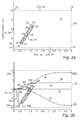
- a predicted traffic environment 12 for the host vehicle 10 is established in a time-lateral position domain t-y, see figs. 2a-b .
- the predicted traffic environment 12 comprises a traffic object 14.
- the traffic object 14 is moving.
- the traffic object 14 may for example be another vehicle.
- the traffic object 14 is represented in the time-lateral position domain by an object prediction representation 16.
- the object prediction representation 16 of the traffic object 14 includes a set of points 18 connected by straight lines 20, here resulting in a parallelogram-shaped object prediction representation 16.
- the method disclosed in "METHOD FOR PROVIDING AN OBJECT PREDICTION REPRESENTATION” comprises: establishing host vehicle 126 in a longitudinal-lateral coordinate system at a starting time t0, the host vehicle being represented by at least one reference point 110a, 110b in the coordinate system; detecting an object, and establishing the object in the coordinate system at the starting time t0, the object being represented by a plurality of object reference points 112a-d along the perimeter of the object, wherein movement of the object is determined; simulating movement of the host vehicle and the object in the longitudinal-lateral coordinate system based on their initial positions at the starting time t0 and a (longitudinal) movement 114 of the host vehicle and the determined movement 116 of the object, wherein points in time t0-n when
- the traffic object 14 may be detected using external sensors, such as cameras and/or radar sensors, on the host vehicle 10, and the object prediction representation 16 may be determined using the host vehicle's electronic control unit (ECU).
- ECU electronice control unit
- the predicted traffic environment 10 further comprises two additional traffic object 22a-b.
- the two additional traffic objects may be stationary.
- the two additional traffic object 22a-b are lane markings. Each lane marking may be represented by two points 18' connected by a straight line 20'.
- a start node 24 of the host vehicle 10 in the predicted traffic environment 12 is determined, based on its initial position relative to the traffic object.
- the start node 24 has host vehicle initial conditions. Specifically, the start node 24 has a start time and a start lateral position, which in the time-lateral position domain of fig. 2a-b coincides with origin.
- the start node 24 may also have at least one additional condition, such as an initial lateral motion. But in the present example the initial lateral motion is zero.
- an end node 26 of the host vehicle 10 in the predicted traffic environment 12 is defined.
- the end node 26 has desired end conditions.
- the end node 26 may have an end time, but no predefined end lateral position.
- the end node 26 has a tolerance in lateral position.
- the end lateral position is up for the present method to determine. In the present example the end time is five seconds.
- step S4 several boundary nodes 28a-d are placed around the object prediction representation 16, see fig. 2b .
- Each boundary node 28a-d is placed a predetermined lateral distance from a respective corner of the object prediction representation 16, as illustrated in fig. 2b .
- the predetermined lateral distance may be half the width of the host vehicle plus a predetermined safety margin.
- boundary nodes 28e-h may be placed the predetermined lateral distance from the points 18 indicating the lane markings.
- boundary nodes can be created for any type of object that can be represented by a set of points, connected by straight lines, in the t-y space. This flexibility in input makes the present method suitable for a plurality of functions and applications.
- Each boundary node 28a-h may also have at least one boundary condition, such as a required lateral velocity, tolerance in lateral (y) position, tolerance in time, etc.
- the at least one boundary conditions may affect node connections to and/or from the boundary nodes, see further below.
- step S5 various node connections are set between the start node 24, the boundary nodes 28a-h, and the end node 26.
- one node connection is a straight horizontal line 30 in the time-lateral position domain going directly from the start node 24 to the end node 26.
- Other node connections may be splines.
- a spline is a smooth polynomial function, and the spline may consist of one or more segments.
- the node connection between the start node 24 and the boundary node 28f of the lower lane marking may be a spline 32.
- Spline 34a is open-state, and spline 34b is closed-state, as will be explained further below.
- spline 34b is closed-state, as will be explained further below.
- the node connection 38 is also a spline, and 36a and 38 together make up a complete path.
- the node connections 30,32,34a-b,36a-b,38,40,42 define a connectivity map for the predicted traffic environment 12.
- rules applicable to different traffic problems, which rules ensure that some node connections are not set in the connectivity map, though they might be theoretically possible. This reduces the search space and ensures quicker processing in the next step S6. Examples of such rules include: no node connections backwards in time, no node connections from a stationary object to a moving object, no node connections between two boundary nodes of the same moving object, etc.
- each spline may have piecewise constant magnitude of lateral jerk, see figures 3-4 .
- spline 44' ends with a lateral motion other than zero (velocity ⁇ 0), whereby it is designated as open-state, like splines 34a and 36a in fig. 2 .
- boundary node 28c may have a boundary condition that required lateral velocity is zero, whereby spline 42 becomes closed-state.
- boundary node 28d may not have any required lateral velocity, whereby both closed-state spline 36b and open-state spline 36a can be set.
- Open-state node connections are typically only used for the closest traffic object, and more specifically for the closest boundary nodes of the closest traffic object, for example boundary nodes 28a and 28d for traffic object 14.
- the boundary condition may also affect the number of segments of the spline. For example, spline 36b has more segments than spline 36a. Consequently, if boundary node 28d had a required lateral velocity not equal to zero resulting in that only open-state spline 36a could be set, that would mean fewer segments than if boundary node 28d had a required lateral velocity equal to zero resulting in that only closed-state spline 36b could be set.
- boundary node 28g could be a line node, which has a tolerance in time (boundary condition), whereby spline 38 could be designated as line-state.
- a line node may be placed wherever the distance in time between two points of an object exceeds a certain threshold.
- line-state splines may be used for long traffic objects, such as the lane markings 22a-b, or a moving traffic objects that extend over a long time.
- a line-state spline aims to become tangential to the traffic object, whereby the lateral velocity and acceleration (boundary conditions) of the corresponding line node may be fixed.
- any lateral motion at the end of a node connection is carried over to the start of a subsequent node connection.
- the end of spline 36a at boundary node 28d has the same lateral motion as the beginning of the subsequent spline 38 leaving boundary node 28d.
- step S6 the nodes of the connectivity map are traversed using a graph-search algorithm, in order to reach the end time with the objective of minimizing a cost function, for example maximum lateral jerk.
- the path i.e. the node connection or interconnected node connections
- the path i.e. the node connection or interconnected node connections
- An A* search algorithm may for example be used.
- other graph search algorithms may be used.
- maximum lateral acceleration or sum of lateral movement could be used as the cost function, for example.
- node connections 30 and 32 are disregarded as they pass through the object predictions representation 16.
- Node connection 42 may also be disregarded since it passes inside the boundary node 28d.
- node connection 34a from boundary point 28a since a boundary condition of lateral velocity is likely violated given the lower lane marking. Roughly speaking, should the host vehicle 10 take this path it may end up crossing the lane marking.
- node connection 34b from boundary point 28a since the maximum lateral jerk appears indeed higher than for node connections 36a-b.
- node connection 36a can continue with node connection 38 and reach the end node 26 node without colliding with any of the objects 14 and 22a-b.
- connection 36b could continue with node connection 40 and also reach the end node 36 without collision.
- the graph-search algorithm here selects node connections 36a+38 as the evasive path, since the maximum lateral jerk for path 36a+38 is lower than for path 36b+40.
- the closed-state node connection 36b requires some more turning of the host vehicle 10 than open-state node connection 36a. However, if the upper/left lane marking is moved closer to the host vehicle 10, the end time of node connection 38 will move backwards, and the path 36b+40 will eventually become the lowest cost path.
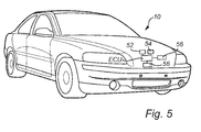
- a control signal to an active safety system such as an automatic steering system 52 and/or automatic braking system 54 (see fig. 5 ), of the host vehicle 10 based on the selected evasive path may be provided.
- an active safety system such as an automatic steering system 52 and/or automatic braking system 54 (see fig. 5 )
- the host vehicle 10 may automatically follow the selected evasive path.
- a risk assessment output signal based on the selected evasive path may be provided.
- the lateral threat severe of the lateral escape path
- the lateral threat may be used as a trigger condition. This threat is found from evaluating the generated escape path (finding maximum lateral acceleration/jerk). Since the generated escape path has a high fidelity (it is has a smooth, steerable characteristic), the threat given will be a good approximation of what a driver would be able to do in the given situation.
- the present method may be embodied in a computer program product 56 comprising code configured to, when executed by a processor or the ECU, perform the method.
- the code may be stored on a computer readable medium (not shown).
- the ECU may in turn be arranged in the host vehicle 10, as illustrated in fig. 5 .
- the host vehicle 10 may for example be a car or a truck or a bus.
- the host vehicle 10 may be an autonomous vehicle.
- the aforementioned external sensors, such as cameras and/or radar sensors, are designated by reference sign 58 in fig. 5 .
- the method present is completely deterministic (requires no stochastic optimization) and is therefore quick and well suited for implementation in production vehicles. Additionally, it can handle any type of object, moving or static, as long as a faithful representation can be done with the proposed object representation (a set of points connected by straight lines in t-y space).
- the present method may also determine an evasive path for the host vehicle in a predicted traffic environment with several moving traffic objects.
Landscapes
- Engineering & Computer Science (AREA)
- Transportation (AREA)
- Mechanical Engineering (AREA)
- Automation & Control Theory (AREA)
- Physics & Mathematics (AREA)
- General Physics & Mathematics (AREA)
- Radar, Positioning & Navigation (AREA)
- Remote Sensing (AREA)
- Chemical & Material Sciences (AREA)
- Combustion & Propulsion (AREA)
- Traffic Control Systems (AREA)
Abstract
Description
- The present invention relates to a method for determining an evasive path for a host vehicle. The present invention also relates to a corresponding computer program product. The present invention also relates to a vehicle.
- While vehicles have been developed to be progressively safer through decades of improved mechanical structures and materials traffic accidents still do occur. Whether it is by human error, external factors or material failure there is has been a need to take a more proactive approach to complement the passive safety arrangements. Developments in the electronics field have provided new smaller, precise and more cost efficient sensors, data processors and data communication means that allow systems that can actively detect and interpret a traffic situation. Accordingly, one system may provide the driver with a warning message to call the attention of the driver to the drifting out of lane, or a system may brake autonomously. However, current advanced driver assistance systems used in for instance auto braking and lane keeping aid functions are commonly scenario-specific. For example, an automatic brake function for intersection may use a completely different algorithm than an automatic brake function for freeway driving. This is inefficient from a data processing perspective in terms of the whole vehicle and from a development cost perspective. Furthermore, this counteracts development of new functionality as multiple algorithms have to be maintained and extended for the life time of a vehicle platform.
- Hence, there exists a need for a method that may take a more holistic interpretation of a traffic environment and which provides input data to e.g. the different warning interfaces and/or the controlling systems for collision avoidance or collision mitigation in vehicles.
- Furthermore,
US2005/0192749 (Flann et al. ) discloses a path planner and a method for determining a path for a vehicle comprises defining a starting point for the vehicle. A termination point is defined. An obstacle detector detects one or more obstacles in a work area between the starting point and the termination point. A boundary zone is defined about each corresponding obstacle. Candidate paths are identified between the starting point and the termination point. Each candidate path only intersects each boundary zone once for each corresponding obstacle. An economic cost is estimated for traversing each candidate path or a portion thereof between the starting point and the termination point. A preferential path is selected from the identified candidate paths based on the preferential path being associated with a lowest estimated economic cost. - It is an object of the present invention to provide an improved method for determining an evasive path for a host vehicle.
- According to a first aspect of the present invention, there is provided a method for determining an evasive path for a host vehicle, the method comprising: establishing a predicted traffic environment of the host vehicle in a time-lateral position domain, the predicted traffic environment comprising an object prediction representation of a traffic object; determining a start node for the host vehicle, the start node representing a start time and a start lateral position in the predicted traffic environment; defining an end node for the host vehicle, the end node representing an end time in the predicted traffic environment; placing several boundary nodes relative to the object prediction representation in the predicted traffic environment between the start node and the end node; setting node connections between the start node, the boundary nodes, and the end node, thereby defining a connectivity map with possible node connections in the predicted traffic environment; and traversing the nodes using a graph-search algorithm in order to find a path from the start node to the end node with a lowest cost, whereby the path with the lowest cost is selected as the evasive path for the host vehicle.
- The lowest cost may be the lowest cost of maximum lateral jerk. Alternatively, maximum lateral acceleration or sum of lateral movement could be used as cost function.
- Said node connections may include splines. Each spline may have a piecewise constant magnitude of lateral jerk.
- Any lateral motion at the end of a node connection may be carried over to the start of a subsequent node connection.
- Any node connections passing through the object prediction representation may be disregarded when traversing the nodes.
- The object prediction representation of the traffic object may include a set of points connected by straight lines, wherein each boundary node is placed a predetermined lateral distance from a respective corner of the object prediction representation. The predetermined lateral distance may be half the width of the host vehicle and an additional predetermined safety margin.
- The method further may further comprise: giving each boundary node at least one boundary condition, such as required lateral velocity, tolerance in lateral position, and/or tolerance in time.
- The graph-search algorithm may be an A* search algorithm.
- The method may further comprise: providing a control signal to an automatic steering system and/or automatic braking system of the host vehicle based on the selected evasive path.
- The method may further comprise: providing a risk assessment output signal based on the selected evasive path.
- According to a second aspect of the present invention, there is provided a computer program product comprising code configured to, when executed by a processor or an electronic control unit, perform the method according to any one of the preceding claims. This aspects may exhibit the same or similar feature and/technical effects as the first aspect. The code may be stored on a computer readable medium.
- According to a third aspect of the present invention, there is provided vehicle comprising an electronic control unit configured to perform the method according to the first aspect. This aspects may exhibit the same or similar feature and/technical effects as the first and second aspects. The electronic control unit may further be configured to provide a control signal based on the selected evasive path, wherein the vehicle further comprises an active safety system adapted to automatically control the vehicle based on said control signal.
- Further features of, and advantages with, the present invention will become apparent when studying the appended claims and the following description. The skilled addressee realize that different features of the present invention may be combined to create embodiments other than those described in the following, without departing from the scope of the present invention.
- These and other aspects of the present invention will now be described in more detail, with reference to the appended drawings showing exemplary embodiments of the present invention, in which:
-
Fig. 1 is a flowchart of a method for determining an evasive path for a host vehicle. -
Figs. 2a-b show a predicted traffic environment in a time-lateral position domain. -
Fig. 3 shows an exemplary closed spline and the associated position, velocity, acceleration and jerk. -
Fig. 4 shows an exemplary open spline and the associated position, velocity, acceleration and jerk. -
Fig. 5 is a schematic view of a vehicle. -
Fig. 6 is an exemplary scenario for a method for providing an object prediction representation. - The present invention will now be described more fully hereinafter with reference to the accompanying drawings, in which exemplary embodiments of the invention are shown. This invention may, however, be embodied in many different forms and should not be construed as limited to the embodiments set forth herein; rather, these embodiments are provided for thoroughness and completeness, and fully convey the scope of the invention to the skilled addressee. Like reference characters refer to like elements throughout.
-
Fig. 1 is a flowchart of a method for determining an evasive path for a host vehicle. - In step S1, a predicted
traffic environment 12 for thehost vehicle 10 is established in a time-lateral position domain t-y, seefigs. 2a-b . The predictedtraffic environment 12 comprises a traffic object 14. The traffic object 14 is moving. The traffic object 14 may for example be another vehicle. The traffic object 14 is represented in the time-lateral position domain by an object prediction representation 16. The object prediction representation 16 of the traffic object 14 includes a set ofpoints 18 connected bystraight lines 20, here resulting in a parallelogram-shaped object prediction representation 16. - An exemplary way to determining the object prediction representation is disclosed in applicant's co-pending patent application entitled "METHOD FOR PROVIDING AN OBJECT PREDICTION REPRESENTATION", the contents of which herein is incorporated by reference. The method disclosed in "METHOD FOR PROVIDING AN OBJECT PREDICTION REPRESENTATION" comprises: establishing
host vehicle 126 in a longitudinal-lateral coordinate system at a starting time t0, the host vehicle being represented by at least onereference point object reference points 112a-d along the perimeter of the object, wherein movement of the object is determined; simulating movement of the host vehicle and the object in the longitudinal-lateral coordinate system based on their initial positions at the starting time t0 and a (longitudinal)movement 114 of the host vehicle and thedetermined movement 116 of the object, wherein points in time t0-n when the at least one reference point of the host vehicle and an object reference point of the plurality of object reference points have the same longitudinal position are detected, and wherein for each detected point in time an associated lateral position y1-n of the object reference point at the detected point in time is detected; and establishing theobject prediction representation 118 in a time-lateral domain based on the detected points in time and the associated lateral positions.Fig. 6 shows an exemplary scenario using the method for providing the object prediction representation. - Returning to
figs. 1 and2a-b , the traffic object 14 may be detected using external sensors, such as cameras and/or radar sensors, on thehost vehicle 10, and the object prediction representation 16 may be determined using the host vehicle's electronic control unit (ECU). - The predicted
traffic environment 10 further comprises twoadditional traffic object 22a-b. The two additional traffic objects may be stationary. In the present example, the twoadditional traffic object 22a-b are lane markings. Each lane marking may be represented by two points 18' connected by a straight line 20'. - In step S2, a start node 24 of the
host vehicle 10 in the predictedtraffic environment 12 is determined, based on its initial position relative to the traffic object. The start node 24 has host vehicle initial conditions. Specifically, the start node 24 has a start time and a start lateral position, which in the time-lateral position domain offig. 2a-b coincides with origin. The start node 24 may also have at least one additional condition, such as an initial lateral motion. But in the present example the initial lateral motion is zero. - In step S3, an
end node 26 of thehost vehicle 10 in the predictedtraffic environment 12 is defined. Theend node 26 has desired end conditions. Specifically, theend node 26 may have an end time, but no predefined end lateral position. In other words, theend node 26 has a tolerance in lateral position. The end lateral position is up for the present method to determine. In the present example the end time is five seconds. - In step S4,
several boundary nodes 28a-d are placed around the object prediction representation 16, seefig. 2b . Eachboundary node 28a-d is placed a predetermined lateral distance from a respective corner of the object prediction representation 16, as illustrated infig. 2b . The predetermined lateral distance may be half the width of the host vehicle plus a predetermined safety margin. Likewise,boundary nodes 28e-h may be placed the predetermined lateral distance from thepoints 18 indicating the lane markings. Basically, boundary nodes can be created for any type of object that can be represented by a set of points, connected by straight lines, in the t-y space. This flexibility in input makes the present method suitable for a plurality of functions and applications. Eachboundary node 28a-h may also have at least one boundary condition, such as a required lateral velocity, tolerance in lateral (y) position, tolerance in time, etc. The at least one boundary conditions may affect node connections to and/or from the boundary nodes, see further below. - In step S5, various node connections are set between the start node 24, the
boundary nodes 28a-h, and theend node 26. For example, one node connection is a straighthorizontal line 30 in the time-lateral position domain going directly from the start node 24 to theend node 26. Other node connections may be splines. A spline is a smooth polynomial function, and the spline may consist of one or more segments. For example, the node connection between the start node 24 and theboundary node 28f of the lower lane marking may be aspline 32. Between the start node 24 and theboundary node 28a of the object prediction representation 16, there may be twosplines Spline 34a is open-state, andspline 34b is closed-state, as will be explained further below. Likewise, there is both an open-state spline 36a and a closed-state spline 36b between the start node 24 andboundary node 28d. There may also be asubsequent node connection 38 fromboundary node 28d toboundary node 28g of the upper lane marking. Thenode connection 38 is also a spline, and 36a and 38 together make up a complete path. There could also be astraight node connection 40 from theboundary node 28d to theend node 26. There may also be a node connection/spline 42 from the start node 24 to theboundary node 28c. Thenode connections traffic environment 12. - There may also be rules, applicable to different traffic problems, which rules ensure that some node connections are not set in the connectivity map, though they might be theoretically possible. This reduces the search space and ensures quicker processing in the next step S6. Examples of such rules include: no node connections backwards in time, no node connections from a stationary object to a moving object, no node connections between two boundary nodes of the same moving object, etc.
- Further, each spline may have piecewise constant magnitude of lateral jerk, see
figures 3-4 . Jerk is defined as the rate of change of acceleration. That is, the derivative of acceleration with respect to time, the second derivative of velocity, or the third derivative of position. This is illustrated infig. 3 , which shows position 44, velocity 46, acceleration 48 and jerk 50 for a spline 44 over time, wherein jmax = |jmin|. The spline 44 ends with a lateral motion equal to zero (velocity = 0), whereby it is designated as closed-state, likesplines fig. 2b .Fig. 4 shows position 44', velocity 46', acceleration 48' and jerk 50' for another spline 44' over time, wherein jmax = |jmin|, albeit the value may be different than infig. 3 . The spline 44' ends with a lateral motion other than zero (velocity ≠ 0), whereby it is designated as open-state, likesplines fig. 2 . - Whether a spline is closed-state or open-state may be governed by the boundary condition(s) of the boundary node in question. For example, in
fig. 2b boundary node 28c may have a boundary condition that required lateral velocity is zero, wherebyspline 42 becomes closed-state. Further,boundary node 28d may not have any required lateral velocity, whereby both closed-state spline 36b and open-state spline 36a can be set. Open-state node connections are typically only used for the closest traffic object, and more specifically for the closest boundary nodes of the closest traffic object, forexample boundary nodes - The boundary condition may also affect the number of segments of the spline. For example,
spline 36b has more segments thanspline 36a. Consequently, ifboundary node 28d had a required lateral velocity not equal to zero resulting in that only open-state spline 36a could be set, that would mean fewer segments than ifboundary node 28d had a required lateral velocity equal to zero resulting in that only closed-state spline 36b could be set. - Furthermore,
boundary node 28g could be a line node, which has a tolerance in time (boundary condition), wherebyspline 38 could be designated as line-state. A line node may be placed wherever the distance in time between two points of an object exceeds a certain threshold. Hence, line-state splines may be used for long traffic objects, such as thelane markings 22a-b, or a moving traffic objects that extend over a long time. A line-state spline aims to become tangential to the traffic object, whereby the lateral velocity and acceleration (boundary conditions) of the corresponding line node may be fixed. - It is also noted in
fig. 2b that any lateral motion at the end of a node connection is carried over to the start of a subsequent node connection. For example, the end ofspline 36a atboundary node 28d has the same lateral motion as the beginning of thesubsequent spline 38 leavingboundary node 28d. - Returning to
fig. 1 , in step S6 the nodes of the connectivity map are traversed using a graph-search algorithm, in order to reach the end time with the objective of minimizing a cost function, for example maximum lateral jerk. The path (i.e. the node connection or interconnected node connections) between the start node 24 and theend node 26 which has the lowest maximum lateral jerk and which avoids collision with theobjects 14 and 22a-b is then selected as the evasive path for thehost vehicle 10. Using a graph-search algorithm ensures that the end time is quickly reached, whereby the most suitable path can be found without having to traverse all possible paths/node connections. An A* search algorithm may for example be used. However, also other graph search algorithms may be used. Furthermore, instead of maximum lateral jerk, maximum lateral acceleration or sum of lateral movement could be used as the cost function, for example. - In the present example of
fig. 2b ,node connections Node connection 42 may also be disregarded since it passes inside theboundary node 28d. Further, there is no point in continue withnode connection 34a fromboundary point 28a since a boundary condition of lateral velocity is likely violated given the lower lane marking. Roughly speaking, should thehost vehicle 10 take this path it may end up crossing the lane marking. There is no point in continue withnode connection 34b fromboundary point 28a since the maximum lateral jerk appears indeed higher than fornode connections 36a-b. Turning then tonode connections 36a-b,node connection 36a can continue withnode connection 38 and reach theend node 26 node without colliding with any of theobjects 14 and 22a-b. Likewiseconnection 36b could continue withnode connection 40 and also reach the end node 36 without collision. However, the graph-search algorithm here selectsnode connections 36a+38 as the evasive path, since the maximum lateral jerk forpath 36a+38 is lower than forpath 36b+40. In particular, the closed-state node connection 36b requires some more turning of thehost vehicle 10 than open-state node connection 36a. However, if the upper/left lane marking is moved closer to thehost vehicle 10, the end time ofnode connection 38 will move backwards, and thepath 36b+40 will eventually become the lowest cost path. - In an optional step S7, a control signal to an active safety system, such as an
automatic steering system 52 and/or automatic braking system 54 (seefig. 5 ), of thehost vehicle 10 based on the selected evasive path may be provided. In this way, thehost vehicle 10 may automatically follow the selected evasive path. Alternatively, a risk assessment output signal based on the selected evasive path may be provided. For example, for auto braking applications, the lateral threat (severity of the lateral escape path) may be used as a trigger condition. This threat is found from evaluating the generated escape path (finding maximum lateral acceleration/jerk). Since the generated escape path has a high fidelity (it is has a smooth, steerable characteristic), the threat given will be a good approximation of what a driver would be able to do in the given situation. - The present method may be embodied in a
computer program product 56 comprising code configured to, when executed by a processor or the ECU, perform the method. The code may be stored on a computer readable medium (not shown). The ECU may in turn be arranged in thehost vehicle 10, as illustrated infig. 5 . Thehost vehicle 10 may for example be a car or a truck or a bus. Thehost vehicle 10 may be an autonomous vehicle. The aforementioned external sensors, such as cameras and/or radar sensors, are designated byreference sign 58 infig. 5 . - Furthermore, the method present is completely deterministic (requires no stochastic optimization) and is therefore quick and well suited for implementation in production vehicles. Additionally, it can handle any type of object, moving or static, as long as a faithful representation can be done with the proposed object representation (a set of points connected by straight lines in t-y space).
- Furthermore, even though only one moving traffic object has been shown in
fig. 2 , the present method may also determine an evasive path for the host vehicle in a predicted traffic environment with several moving traffic objects. - Even though the invention has been described with reference to specific exemplifying embodiments thereof, many different alterations, modifications and the like will become apparent for those skilled in the art. Variations to the disclosed embodiments can be understood and effected by the skilled addressee in practicing the claimed invention, from a study of the drawings, the disclosure, and the appended claims.
- Furthermore, in the claims, the word "comprising" does not exclude other elements or steps, and the indefinite article "a" or "an" does not exclude a plurality.
Claims (17)
- A method for determining an evasive path for a host vehicle (10), the method comprising:- establishing (S1) a predicted traffic environment (12) of the host vehicle in a time-lateral position domain, the predicted traffic environment comprising an object prediction representation (16) of a traffic object;- determining (S2) a start node (24) for the host vehicle, the start node representing a start time and a start lateral position in the predicted traffic environment;- defining (S3) an end node (26) for the host vehicle, the end node representing an end time in the predicted traffic environment;- placing (S4) several boundary nodes (28) relative to the object prediction representation in the predicted traffic environment between the start node and the end node;- setting (S5) node connections (30,32,34a-b,36a-b,38,40,42) between the start node, the boundary nodes, and the end node, thereby defining a connectivity map with possible node connections in the predicted traffic environment; and- traversing (S6) the nodes using a graph-search algorithm in order to find a path from the start node to the end node with a lowest cost, whereby the path with the lowest cost is selected as the evasive path for the host vehicle.
- The method according to claim 1, wherein the lowest cost is the lowest cost of maximum lateral jerk.
- The method according to claim 1 or 2, wherein said node connections include splines.
- The method according to claim 2 and 3, wherein each spline has a piecewise constant magnitude of lateral jerk.
- The method according to any of the preceding claims, wherein any lateral motion at the end of a node connection is carried over to the start of a subsequent node connection.
- The method according to any of the preceding claims, wherein any node connections passing through the object prediction representation are disregarded when traversing the nodes.
- The method according to any of the preceding claims, wherein the object prediction representation of the traffic object includes a set of points connected by straight lines, and wherein each boundary node is placed a predetermined lateral distance from a respective corner of the object prediction representation.
- The method of claim 7, wherein the predetermined lateral distance is half the width of the host vehicle and an additional predetermined safety margin.
- The method according to any preceding claim, which method further comprises:- giving each boundary node at least one boundary condition.
- The method of claim 9, wherein the at least one boundary condition is selected from the group comprising: required lateral velocity, tolerance in lateral position, and tolerance in time.
- The method according to any preceding claim, wherein the graph-search algorithm is an A* search algorithm.
- The method according to any of the preceding claims, further comprising:- providing a control signal to an automatic steering system (52) and/or automatic braking system (54) of the host vehicle based on the selected evasive path.
- The method according to any of the preceding claims, further comprising:- providing a risk assessment output signal based on the selected evasive path.
- A computer program product (56) comprising code configured to, when executed by a processor or an electronic control unit, perform the method according to any one of the preceding claims.
- The computer program product according to claim 14, wherein the code is stored on a computer readable medium.
- A vehicle (10) comprising an electronic control unit configured to perform the method according to any one of the claims 1-13.
- The vehicle according to claim 16, wherein the electronic control unit is further configured to provide a control signal based on the selected evasive path, and wherein the vehicle further comprises an active safety system adapted to automatically control the vehicle based on said control signal.
Priority Applications (4)
| Application Number | Priority Date | Filing Date | Title |
|---|---|---|---|
| EP14167465.5A EP2942250B1 (en) | 2014-05-08 | 2014-05-08 | Method for determining an evasive path for a host vehicle |
| CN201580022035.8A CN106414202B (en) | 2014-05-08 | 2015-05-07 | The method for evading path for determining main vehicle |
| US15/307,955 US10410521B2 (en) | 2014-05-08 | 2015-05-07 | Method for determining an evasive path for a host vehicle |
| PCT/EP2015/060082 WO2015169907A1 (en) | 2014-05-08 | 2015-05-07 | Method for determining an evasive path for a host vehicle |
Applications Claiming Priority (1)
| Application Number | Priority Date | Filing Date | Title |
|---|---|---|---|
| EP14167465.5A EP2942250B1 (en) | 2014-05-08 | 2014-05-08 | Method for determining an evasive path for a host vehicle |
Publications (2)
| Publication Number | Publication Date |
|---|---|
| EP2942250A1 true EP2942250A1 (en) | 2015-11-11 |
| EP2942250B1 EP2942250B1 (en) | 2017-02-01 |
Family
ID=50771407
Family Applications (1)
| Application Number | Title | Priority Date | Filing Date |
|---|---|---|---|
| EP14167465.5A Active EP2942250B1 (en) | 2014-05-08 | 2014-05-08 | Method for determining an evasive path for a host vehicle |
Country Status (4)
| Country | Link |
|---|---|
| US (1) | US10410521B2 (en) |
| EP (1) | EP2942250B1 (en) |
| CN (1) | CN106414202B (en) |
| WO (1) | WO2015169907A1 (en) |
Cited By (5)
| Publication number | Priority date | Publication date | Assignee | Title |
|---|---|---|---|---|
| WO2017177969A1 (en) * | 2016-04-15 | 2017-10-19 | Podway Ltd | System for and method of maximizing utilization of a closed transport system in an on-demand network |
| US10359783B2 (en) | 2017-02-28 | 2019-07-23 | Warfarer, Inc. | Transportation system |
| US10467915B2 (en) | 2017-06-09 | 2019-11-05 | Wayfarer, Inc. | Autonomous vehicle system employing time domain dynamic buffers when matching passengers and vehicles |
| US11958516B2 (en) | 2018-02-12 | 2024-04-16 | Glydways, Inc. | Autonomous rail or off rail vehicle movement and system among a group of vehicles |
| US12019454B2 (en) | 2020-03-20 | 2024-06-25 | Glydways Inc. | Vehicle control schemes for autonomous vehicle system |
Families Citing this family (15)
| Publication number | Priority date | Publication date | Assignee | Title |
|---|---|---|---|---|
| US9857795B2 (en) * | 2016-03-24 | 2018-01-02 | Honda Motor Co., Ltd. | System and method for trajectory planning for unexpected pedestrians |
| KR101891612B1 (en) * | 2016-09-30 | 2018-08-24 | 엘지전자 주식회사 | Autonomous vehicle |
| KR102673055B1 (en) * | 2016-12-09 | 2024-06-10 | 현대자동차주식회사 | Vehicle and method for controlling thereof |
| JP6823512B2 (en) * | 2017-03-16 | 2021-02-03 | 本田技研工業株式会社 | Route determination device, vehicle control device, route determination method, and program |
| US10688991B2 (en) * | 2018-01-24 | 2020-06-23 | GM Global Technology Operations LLC | Systems and methods for unprotected maneuver mitigation in autonomous vehicles |
| US10816977B2 (en) * | 2018-01-26 | 2020-10-27 | Baidu Usa Llc | Path and speed optimization fallback mechanism for autonomous vehicles |
| US11199842B2 (en) * | 2018-06-26 | 2021-12-14 | Baidu Usa Llc | Determining driving paths for autonomous driving using parallel processing |
| US11157437B2 (en) * | 2018-09-26 | 2021-10-26 | Micron Technology, Inc. | Memory pooling between selected memory resources via a base station |
| DE102018008624A1 (en) * | 2018-10-31 | 2020-04-30 | Trw Automotive Gmbh | Control system and control method for sampling-based planning of possible trajectories for motor vehicles |
| DE102019216378A1 (en) * | 2019-10-24 | 2021-04-29 | Robert Bosch Gmbh | Determination of a vehicle trajectory using limit cost functions |
| CN110723139A (en) * | 2019-11-15 | 2020-01-24 | 联想(北京)有限公司 | Vehicle control method, electronic equipment and vehicle |
| JP7460458B2 (en) * | 2020-06-17 | 2024-04-02 | 日立Astemo株式会社 | Vehicle motion control device and vehicle motion control method |
| CN112644487B (en) * | 2021-01-07 | 2022-12-13 | 广州小鹏自动驾驶科技有限公司 | A method and device for automatic driving |
| CN115775216B (en) * | 2021-09-07 | 2026-04-07 | 上海微创卜算子医疗科技有限公司 | Methods, electronic devices, and storage media for acquiring vascular information |
| CN114475658B (en) * | 2022-02-23 | 2023-08-25 | 广州小鹏自动驾驶科技有限公司 | Automatic driving speed planning method and device, vehicle and storage medium |
Citations (7)
| Publication number | Priority date | Publication date | Assignee | Title |
|---|---|---|---|---|
| US20040090117A1 (en) * | 2000-07-26 | 2004-05-13 | Ingo Dudeck | Automatic brake and steering system and method for a vehicle |
| US20050125155A1 (en) * | 2003-12-05 | 2005-06-09 | Fuji Jukogyo Kabushiki Kaisha | Vehicle traveling control device |
| US20050192749A1 (en) | 2003-10-07 | 2005-09-01 | Flann Nicholas S. | Point -to-point path planning |
| JP2006154967A (en) * | 2004-11-25 | 2006-06-15 | Nissan Motor Co Ltd | Risk minimum trajectory generation device and danger situation warning device using the same |
| DE102006042666A1 (en) * | 2006-09-12 | 2008-03-27 | Robert Bosch Gmbh | Method for avoiding or mitigating the collision of a vehicle with at least one object |
| US20110106361A1 (en) * | 2007-03-16 | 2011-05-05 | Martin Staempfle | Method for the calculation of a collision-preventing trajectory for a driving maneuver of a vehicle |
| US20130054128A1 (en) * | 2011-08-31 | 2013-02-28 | GM Global Technology Operations LLC | System and method for collision avoidance maneuver path determination with jerk limit |
Family Cites Families (16)
| Publication number | Priority date | Publication date | Assignee | Title |
|---|---|---|---|---|
| EP0750238B1 (en) * | 1995-06-20 | 2000-03-01 | Honeywell Inc. | Integrated ground collision avoidance system |
| US7788071B2 (en) | 2004-12-03 | 2010-08-31 | Telekinesys Research Limited | Physics simulation apparatus and method |
| WO2007031580A1 (en) * | 2005-09-15 | 2007-03-22 | Continental Teves Ag & Co. Ohg | Method and device for predicting a displacement path |
| WO2007102367A1 (en) * | 2006-02-28 | 2007-09-13 | Toyota Jidosha Kabushiki Kaisha | Object course prediction method, device, program, and automatic driving system |
| JP2009120116A (en) * | 2007-11-16 | 2009-06-04 | Hitachi Ltd | Vehicle collision avoidance support device |
| JP5070171B2 (en) | 2008-09-19 | 2012-11-07 | 日立オートモティブシステムズ株式会社 | Vehicle control device |
| US20100209884A1 (en) * | 2009-02-18 | 2010-08-19 | Gm Global Technology Operations, Inc. | Driving skill recognition based on vehicle left and right turns |
| US8170725B2 (en) * | 2009-02-18 | 2012-05-01 | GM Global Technology Operations LLC | Vehicle stability enhancement control adaptation to driving skill based on highway on/off ramp maneuver |
| US20100209889A1 (en) * | 2009-02-18 | 2010-08-19 | Gm Global Technology Operations, Inc. | Vehicle stability enhancement control adaptation to driving skill based on multiple types of maneuvers |
| US20100209890A1 (en) * | 2009-02-18 | 2010-08-19 | Gm Global Technology Operations, Inc. | Vehicle stability enhancement control adaptation to driving skill with integrated driving skill recognition |
| US20100209886A1 (en) * | 2009-02-18 | 2010-08-19 | Gm Global Technology Operations, Inc. | Driving skill recognition based on u-turn performance |
| JP5617677B2 (en) | 2011-02-17 | 2014-11-05 | トヨタ自動車株式会社 | Driving assistance device |
| US8466807B2 (en) * | 2011-06-01 | 2013-06-18 | GM Global Technology Operations LLC | Fast collision detection technique for connected autonomous and manual vehicles |
| US20140063061A1 (en) | 2011-08-26 | 2014-03-06 | Reincloud Corporation | Determining a position of an item in a virtual augmented space |
| US20130249948A1 (en) | 2011-08-26 | 2013-09-26 | Reincloud Corporation | Providing interactive travel content at a display device |
| CN104584097B (en) | 2012-08-09 | 2017-04-05 | 丰田自动车株式会社 | Article detection device and drive assistance device |
-
2014
- 2014-05-08 EP EP14167465.5A patent/EP2942250B1/en active Active
-
2015
- 2015-05-07 CN CN201580022035.8A patent/CN106414202B/en not_active Expired - Fee Related
- 2015-05-07 US US15/307,955 patent/US10410521B2/en active Active
- 2015-05-07 WO PCT/EP2015/060082 patent/WO2015169907A1/en not_active Ceased
Patent Citations (7)
| Publication number | Priority date | Publication date | Assignee | Title |
|---|---|---|---|---|
| US20040090117A1 (en) * | 2000-07-26 | 2004-05-13 | Ingo Dudeck | Automatic brake and steering system and method for a vehicle |
| US20050192749A1 (en) | 2003-10-07 | 2005-09-01 | Flann Nicholas S. | Point -to-point path planning |
| US20050125155A1 (en) * | 2003-12-05 | 2005-06-09 | Fuji Jukogyo Kabushiki Kaisha | Vehicle traveling control device |
| JP2006154967A (en) * | 2004-11-25 | 2006-06-15 | Nissan Motor Co Ltd | Risk minimum trajectory generation device and danger situation warning device using the same |
| DE102006042666A1 (en) * | 2006-09-12 | 2008-03-27 | Robert Bosch Gmbh | Method for avoiding or mitigating the collision of a vehicle with at least one object |
| US20110106361A1 (en) * | 2007-03-16 | 2011-05-05 | Martin Staempfle | Method for the calculation of a collision-preventing trajectory for a driving maneuver of a vehicle |
| US20130054128A1 (en) * | 2011-08-31 | 2013-02-28 | GM Global Technology Operations LLC | System and method for collision avoidance maneuver path determination with jerk limit |
Cited By (12)
| Publication number | Priority date | Publication date | Assignee | Title |
|---|---|---|---|---|
| WO2017177969A1 (en) * | 2016-04-15 | 2017-10-19 | Podway Ltd | System for and method of maximizing utilization of a closed transport system in an on-demand network |
| US10345805B2 (en) | 2016-04-15 | 2019-07-09 | Podway Ltd. | System for and method of maximizing utilization of a closed transport system in an on-demand network |
| US10359783B2 (en) | 2017-02-28 | 2019-07-23 | Warfarer, Inc. | Transportation system |
| US11169538B2 (en) | 2017-02-28 | 2021-11-09 | Glydways, Inc. | Transportation system |
| US11592836B2 (en) | 2017-02-28 | 2023-02-28 | Glydways Inc. | Transportation system |
| US11644849B2 (en) | 2017-02-28 | 2023-05-09 | Glydways, Inc. | Transportation system |
| US12013707B2 (en) | 2017-02-28 | 2024-06-18 | Glydways Inc. | Transportation system |
| US12379728B2 (en) | 2017-02-28 | 2025-08-05 | Glydways Inc. | Transportation system |
| US10467915B2 (en) | 2017-06-09 | 2019-11-05 | Wayfarer, Inc. | Autonomous vehicle system employing time domain dynamic buffers when matching passengers and vehicles |
| US11958516B2 (en) | 2018-02-12 | 2024-04-16 | Glydways, Inc. | Autonomous rail or off rail vehicle movement and system among a group of vehicles |
| US12019454B2 (en) | 2020-03-20 | 2024-06-25 | Glydways Inc. | Vehicle control schemes for autonomous vehicle system |
| US12366867B2 (en) | 2020-03-20 | 2025-07-22 | Glydways Inc. | Vehicle control schemes for autonomous vehicle system |
Also Published As
| Publication number | Publication date |
|---|---|
| WO2015169907A1 (en) | 2015-11-12 |
| US10410521B2 (en) | 2019-09-10 |
| EP2942250B1 (en) | 2017-02-01 |
| US20170053532A1 (en) | 2017-02-23 |
| CN106414202B (en) | 2018-09-25 |
| CN106414202A (en) | 2017-02-15 |
Similar Documents
| Publication | Publication Date | Title |
|---|---|---|
| EP2942250B1 (en) | Method for determining an evasive path for a host vehicle | |
| CN110488802B (en) | Decision-making method for dynamic behaviors of automatic driving vehicle in internet environment | |
| US10336268B2 (en) | Method and apparatus for operating a vehicle | |
| KR102610742B1 (en) | Apparatus and method for providing safety strategy of vehicle | |
| US9463806B2 (en) | Consistent behavior generation of a predictive advanced driver assistant system | |
| US20230123418A1 (en) | Method for planning a target trajectory | |
| US9037373B2 (en) | Lateral control apparatus of vehicle and control method of the same | |
| KR102712307B1 (en) | Apparatus and method for preventing vehicle collision | |
| JP6184923B2 (en) | Vehicle collision avoidance device | |
| US12049226B2 (en) | Driver assistance systems | |
| US20140207325A1 (en) | Efficient data flow algorithms for autonomous lane changing, passing and overtaking behaviors | |
| US20190122559A1 (en) | System and method for situation analysis of an autonomous lane change maneuver | |
| EP3456596A1 (en) | Method and device of predicting a possible collision | |
| KR20150110634A (en) | Method for determining an activation criterion for a brake application and emergency brake system for performing the method | |
| EP3623240B1 (en) | Method and system for assisting a driver in the event of a road departure | |
| EP3597511B1 (en) | Method and system for providing a steering guidance to a driver of a host vehicle | |
| CN109795508B (en) | Safe driving control method and device | |
| Nolte et al. | Representing the unknown–impact of uncertainty on the interaction between decision making and trajectory generation | |
| CN114132311A (en) | Method and module for screening dangerous targets for automatic emergency braking of vehicle | |
| US20240166204A1 (en) | Vehicle Collision Threat Assessment | |
| GB2513953B (en) | Method for assisting the driver of a motor vehicle in a collision avoidance manoeuvre | |
| JP2016197279A5 (en) | Collision avoidance device, collision avoidance system, and driving support method | |
| KR102287574B1 (en) | Method and device for operating a vehicle | |
| CN107533802B (en) | Vehicle peripheral information verification device and method | |
| CN114901535B (en) | Systems and methods for predicting vehicle trajectories |
Legal Events
| Date | Code | Title | Description |
|---|---|---|---|
| PUAI | Public reference made under article 153(3) epc to a published international application that has entered the european phase |
Free format text: ORIGINAL CODE: 0009012 |
|
| AK | Designated contracting states |
Kind code of ref document: A1 Designated state(s): AL AT BE BG CH CY CZ DE DK EE ES FI FR GB GR HR HU IE IS IT LI LT LU LV MC MK MT NL NO PL PT RO RS SE SI SK SM TR |
|
| AX | Request for extension of the european patent |
Extension state: BA ME |
|
| 17P | Request for examination filed |
Effective date: 20160502 |
|
| RBV | Designated contracting states (corrected) |
Designated state(s): AL AT BE BG CH CY CZ DE DK EE ES FI FR GB GR HR HU IE IS IT LI LT LU LV MC MK MT NL NO PL PT RO RS SE SI SK SM TR |
|
| GRAP | Despatch of communication of intention to grant a patent |
Free format text: ORIGINAL CODE: EPIDOSNIGR1 |
|
| INTG | Intention to grant announced |
Effective date: 20160914 |
|
| GRAS | Grant fee paid |
Free format text: ORIGINAL CODE: EPIDOSNIGR3 |
|
| GRAA | (expected) grant |
Free format text: ORIGINAL CODE: 0009210 |
|
| AK | Designated contracting states |
Kind code of ref document: B1 Designated state(s): AL AT BE BG CH CY CZ DE DK EE ES FI FR GB GR HR HU IE IS IT LI LT LU LV MC MK MT NL NO PL PT RO RS SE SI SK SM TR |
|
| REG | Reference to a national code |
Ref country code: GB Ref legal event code: FG4D |
|
| REG | Reference to a national code |
Ref country code: CH Ref legal event code: EP Ref country code: AT Ref legal event code: REF Ref document number: 865276 Country of ref document: AT Kind code of ref document: T Effective date: 20170215 |
|
| REG | Reference to a national code |
Ref country code: IE Ref legal event code: FG4D |
|
| REG | Reference to a national code |
Ref country code: DE Ref legal event code: R096 Ref document number: 602014006470 Country of ref document: DE |
|
| REG | Reference to a national code |
Ref country code: SE Ref legal event code: TRGR |
|
| REG | Reference to a national code |
Ref country code: NL Ref legal event code: MP Effective date: 20170201 |
|
| REG | Reference to a national code |
Ref country code: LT Ref legal event code: MG4D |
|
| REG | Reference to a national code |
Ref country code: AT Ref legal event code: MK05 Ref document number: 865276 Country of ref document: AT Kind code of ref document: T Effective date: 20170201 |
|
| PG25 | Lapsed in a contracting state [announced via postgrant information from national office to epo] |
Ref country code: GR Free format text: LAPSE BECAUSE OF FAILURE TO SUBMIT A TRANSLATION OF THE DESCRIPTION OR TO PAY THE FEE WITHIN THE PRESCRIBED TIME-LIMIT Effective date: 20170502 Ref country code: NO Free format text: LAPSE BECAUSE OF FAILURE TO SUBMIT A TRANSLATION OF THE DESCRIPTION OR TO PAY THE FEE WITHIN THE PRESCRIBED TIME-LIMIT Effective date: 20170501 Ref country code: HR Free format text: LAPSE BECAUSE OF FAILURE TO SUBMIT A TRANSLATION OF THE DESCRIPTION OR TO PAY THE FEE WITHIN THE PRESCRIBED TIME-LIMIT Effective date: 20170201 Ref country code: IS Free format text: LAPSE BECAUSE OF FAILURE TO SUBMIT A TRANSLATION OF THE DESCRIPTION OR TO PAY THE FEE WITHIN THE PRESCRIBED TIME-LIMIT Effective date: 20170601 Ref country code: LT Free format text: LAPSE BECAUSE OF FAILURE TO SUBMIT A TRANSLATION OF THE DESCRIPTION OR TO PAY THE FEE WITHIN THE PRESCRIBED TIME-LIMIT Effective date: 20170201 Ref country code: FI Free format text: LAPSE BECAUSE OF FAILURE TO SUBMIT A TRANSLATION OF THE DESCRIPTION OR TO PAY THE FEE WITHIN THE PRESCRIBED TIME-LIMIT Effective date: 20170201 |
|
| PG25 | Lapsed in a contracting state [announced via postgrant information from national office to epo] |
Ref country code: ES Free format text: LAPSE BECAUSE OF FAILURE TO SUBMIT A TRANSLATION OF THE DESCRIPTION OR TO PAY THE FEE WITHIN THE PRESCRIBED TIME-LIMIT Effective date: 20170201 Ref country code: AT Free format text: LAPSE BECAUSE OF FAILURE TO SUBMIT A TRANSLATION OF THE DESCRIPTION OR TO PAY THE FEE WITHIN THE PRESCRIBED TIME-LIMIT Effective date: 20170201 Ref country code: LU Free format text: LAPSE BECAUSE OF NON-PAYMENT OF DUE FEES Effective date: 20170531 Ref country code: PL Free format text: LAPSE BECAUSE OF FAILURE TO SUBMIT A TRANSLATION OF THE DESCRIPTION OR TO PAY THE FEE WITHIN THE PRESCRIBED TIME-LIMIT Effective date: 20170201 Ref country code: BG Free format text: LAPSE BECAUSE OF FAILURE TO SUBMIT A TRANSLATION OF THE DESCRIPTION OR TO PAY THE FEE WITHIN THE PRESCRIBED TIME-LIMIT Effective date: 20170501 Ref country code: RS Free format text: LAPSE BECAUSE OF FAILURE TO SUBMIT A TRANSLATION OF THE DESCRIPTION OR TO PAY THE FEE WITHIN THE PRESCRIBED TIME-LIMIT Effective date: 20170201 Ref country code: PT Free format text: LAPSE BECAUSE OF FAILURE TO SUBMIT A TRANSLATION OF THE DESCRIPTION OR TO PAY THE FEE WITHIN THE PRESCRIBED TIME-LIMIT Effective date: 20170601 Ref country code: LV Free format text: LAPSE BECAUSE OF FAILURE TO SUBMIT A TRANSLATION OF THE DESCRIPTION OR TO PAY THE FEE WITHIN THE PRESCRIBED TIME-LIMIT Effective date: 20170201 Ref country code: NL Free format text: LAPSE BECAUSE OF NON-PAYMENT OF DUE FEES Effective date: 20170201 |
|
| PG25 | Lapsed in a contracting state [announced via postgrant information from national office to epo] |
Ref country code: CZ Free format text: LAPSE BECAUSE OF FAILURE TO SUBMIT A TRANSLATION OF THE DESCRIPTION OR TO PAY THE FEE WITHIN THE PRESCRIBED TIME-LIMIT Effective date: 20170201 Ref country code: EE Free format text: LAPSE BECAUSE OF FAILURE TO SUBMIT A TRANSLATION OF THE DESCRIPTION OR TO PAY THE FEE WITHIN THE PRESCRIBED TIME-LIMIT Effective date: 20170201 Ref country code: SK Free format text: LAPSE BECAUSE OF FAILURE TO SUBMIT A TRANSLATION OF THE DESCRIPTION OR TO PAY THE FEE WITHIN THE PRESCRIBED TIME-LIMIT Effective date: 20170201 Ref country code: RO Free format text: LAPSE BECAUSE OF FAILURE TO SUBMIT A TRANSLATION OF THE DESCRIPTION OR TO PAY THE FEE WITHIN THE PRESCRIBED TIME-LIMIT Effective date: 20170201 Ref country code: IT Free format text: LAPSE BECAUSE OF FAILURE TO SUBMIT A TRANSLATION OF THE DESCRIPTION OR TO PAY THE FEE WITHIN THE PRESCRIBED TIME-LIMIT Effective date: 20170201 |
|
| REG | Reference to a national code |
Ref country code: DE Ref legal event code: R097 Ref document number: 602014006470 Country of ref document: DE |
|
| PG25 | Lapsed in a contracting state [announced via postgrant information from national office to epo] |
Ref country code: DK Free format text: LAPSE BECAUSE OF FAILURE TO SUBMIT A TRANSLATION OF THE DESCRIPTION OR TO PAY THE FEE WITHIN THE PRESCRIBED TIME-LIMIT Effective date: 20170201 Ref country code: SM Free format text: LAPSE BECAUSE OF FAILURE TO SUBMIT A TRANSLATION OF THE DESCRIPTION OR TO PAY THE FEE WITHIN THE PRESCRIBED TIME-LIMIT Effective date: 20170201 |
|
| PLBE | No opposition filed within time limit |
Free format text: ORIGINAL CODE: 0009261 |
|
| STAA | Information on the status of an ep patent application or granted ep patent |
Free format text: STATUS: NO OPPOSITION FILED WITHIN TIME LIMIT |
|
| REG | Reference to a national code |
Ref country code: CH Ref legal event code: PL |
|
| 26N | No opposition filed |
Effective date: 20171103 |
|
| PG25 | Lapsed in a contracting state [announced via postgrant information from national office to epo] |
Ref country code: MC Free format text: LAPSE BECAUSE OF FAILURE TO SUBMIT A TRANSLATION OF THE DESCRIPTION OR TO PAY THE FEE WITHIN THE PRESCRIBED TIME-LIMIT Effective date: 20170201 |
|
| REG | Reference to a national code |
Ref country code: IE Ref legal event code: MM4A |
|
| PG25 | Lapsed in a contracting state [announced via postgrant information from national office to epo] |
Ref country code: SI Free format text: LAPSE BECAUSE OF FAILURE TO SUBMIT A TRANSLATION OF THE DESCRIPTION OR TO PAY THE FEE WITHIN THE PRESCRIBED TIME-LIMIT Effective date: 20170201 Ref country code: CH Free format text: LAPSE BECAUSE OF NON-PAYMENT OF DUE FEES Effective date: 20170531 Ref country code: LI Free format text: LAPSE BECAUSE OF NON-PAYMENT OF DUE FEES Effective date: 20170531 |
|
| REG | Reference to a national code |
Ref country code: FR Ref legal event code: ST Effective date: 20180131 |
|
| PG25 | Lapsed in a contracting state [announced via postgrant information from national office to epo] |
Ref country code: LU Free format text: LAPSE BECAUSE OF NON-PAYMENT OF DUE FEES Effective date: 20170508 |
|
| REG | Reference to a national code |
Ref country code: BE Ref legal event code: MM Effective date: 20170531 |
|
| PG25 | Lapsed in a contracting state [announced via postgrant information from national office to epo] |
Ref country code: IE Free format text: LAPSE BECAUSE OF NON-PAYMENT OF DUE FEES Effective date: 20170508 |
|
| PG25 | Lapsed in a contracting state [announced via postgrant information from national office to epo] |
Ref country code: FR Free format text: LAPSE BECAUSE OF NON-PAYMENT OF DUE FEES Effective date: 20170531 |
|
| PG25 | Lapsed in a contracting state [announced via postgrant information from national office to epo] |
Ref country code: BE Free format text: LAPSE BECAUSE OF NON-PAYMENT OF DUE FEES Effective date: 20170531 |
|
| PG25 | Lapsed in a contracting state [announced via postgrant information from national office to epo] |
Ref country code: MT Free format text: LAPSE BECAUSE OF NON-PAYMENT OF DUE FEES Effective date: 20170508 |
|
| PG25 | Lapsed in a contracting state [announced via postgrant information from national office to epo] |
Ref country code: HU Free format text: LAPSE BECAUSE OF FAILURE TO SUBMIT A TRANSLATION OF THE DESCRIPTION OR TO PAY THE FEE WITHIN THE PRESCRIBED TIME-LIMIT; INVALID AB INITIO Effective date: 20140508 |
|
| PG25 | Lapsed in a contracting state [announced via postgrant information from national office to epo] |
Ref country code: CY Free format text: LAPSE BECAUSE OF FAILURE TO SUBMIT A TRANSLATION OF THE DESCRIPTION OR TO PAY THE FEE WITHIN THE PRESCRIBED TIME-LIMIT Effective date: 20170201 |
|
| PG25 | Lapsed in a contracting state [announced via postgrant information from national office to epo] |
Ref country code: MK Free format text: LAPSE BECAUSE OF FAILURE TO SUBMIT A TRANSLATION OF THE DESCRIPTION OR TO PAY THE FEE WITHIN THE PRESCRIBED TIME-LIMIT Effective date: 20170201 |
|
| PG25 | Lapsed in a contracting state [announced via postgrant information from national office to epo] |
Ref country code: TR Free format text: LAPSE BECAUSE OF FAILURE TO SUBMIT A TRANSLATION OF THE DESCRIPTION OR TO PAY THE FEE WITHIN THE PRESCRIBED TIME-LIMIT Effective date: 20170201 |
|
| PG25 | Lapsed in a contracting state [announced via postgrant information from national office to epo] |
Ref country code: AL Free format text: LAPSE BECAUSE OF FAILURE TO SUBMIT A TRANSLATION OF THE DESCRIPTION OR TO PAY THE FEE WITHIN THE PRESCRIBED TIME-LIMIT Effective date: 20170201 |
|
| PGFP | Annual fee paid to national office [announced via postgrant information from national office to epo] |
Ref country code: SE Payment date: 20240531 Year of fee payment: 11 |
|
| PGFP | Annual fee paid to national office [announced via postgrant information from national office to epo] |
Ref country code: DE Payment date: 20250516 Year of fee payment: 12 |
|
| PGFP | Annual fee paid to national office [announced via postgrant information from national office to epo] |
Ref country code: GB Payment date: 20250515 Year of fee payment: 12 |
|
| PG25 | Lapsed in a contracting state [announced via postgrant information from national office to epo] |
Ref country code: SE Free format text: LAPSE BECAUSE OF NON-PAYMENT OF DUE FEES Effective date: 20250509 |
|
| REG | Reference to a national code |
Ref country code: SE Ref legal event code: EUG |