EP2942182A1 - Method and system for applying a film to a plastic work piece that is to be cured, and a method for producing a plastic work piece - Google Patents
Method and system for applying a film to a plastic work piece that is to be cured, and a method for producing a plastic work piece Download PDFInfo
- Publication number
- EP2942182A1 EP2942182A1 EP15165460.5A EP15165460A EP2942182A1 EP 2942182 A1 EP2942182 A1 EP 2942182A1 EP 15165460 A EP15165460 A EP 15165460A EP 2942182 A1 EP2942182 A1 EP 2942182A1
- Authority
- EP
- European Patent Office
- Prior art keywords
- film
- work piece
- plastic work
- base member
- frame
- Prior art date
- Legal status (The legal status is an assumption and is not a legal conclusion. Google has not performed a legal analysis and makes no representation as to the accuracy of the status listed.)
- Granted
Links
Images

Classifications
-
- B—PERFORMING OPERATIONS; TRANSPORTING
- B32—LAYERED PRODUCTS
- B32B—LAYERED PRODUCTS, i.e. PRODUCTS BUILT-UP OF STRATA OF FLAT OR NON-FLAT, e.g. CELLULAR OR HONEYCOMB, FORM
- B32B37/00—Methods or apparatus for laminating, e.g. by curing or by ultrasonic bonding
- B32B37/0076—Methods or apparatus for laminating, e.g. by curing or by ultrasonic bonding characterised in that the layers are not bonded on the totality of their surfaces
-
- B—PERFORMING OPERATIONS; TRANSPORTING
- B32—LAYERED PRODUCTS
- B32B—LAYERED PRODUCTS, i.e. PRODUCTS BUILT-UP OF STRATA OF FLAT OR NON-FLAT, e.g. CELLULAR OR HONEYCOMB, FORM
- B32B37/00—Methods or apparatus for laminating, e.g. by curing or by ultrasonic bonding
- B32B37/10—Methods or apparatus for laminating, e.g. by curing or by ultrasonic bonding characterised by the pressing technique, e.g. using action of vacuum or fluid pressure
- B32B37/1018—Methods or apparatus for laminating, e.g. by curing or by ultrasonic bonding characterised by the pressing technique, e.g. using action of vacuum or fluid pressure using only vacuum
-
- B—PERFORMING OPERATIONS; TRANSPORTING
- B29—WORKING OF PLASTICS; WORKING OF SUBSTANCES IN A PLASTIC STATE IN GENERAL
- B29C—SHAPING OR JOINING OF PLASTICS; SHAPING OF MATERIAL IN A PLASTIC STATE, NOT OTHERWISE PROVIDED FOR; AFTER-TREATMENT OF THE SHAPED PRODUCTS, e.g. REPAIRING
- B29C63/00—Lining or sheathing, i.e. applying preformed layers or sheathings of plastics; Apparatus therefor
- B29C63/02—Lining or sheathing, i.e. applying preformed layers or sheathings of plastics; Apparatus therefor using sheet or web-like material
- B29C63/16—Lining or sheathing, i.e. applying preformed layers or sheathings of plastics; Apparatus therefor using sheet or web-like material applied by "rubber" bag or diaphragm
-
- B—PERFORMING OPERATIONS; TRANSPORTING
- B29—WORKING OF PLASTICS; WORKING OF SUBSTANCES IN A PLASTIC STATE IN GENERAL
- B29C—SHAPING OR JOINING OF PLASTICS; SHAPING OF MATERIAL IN A PLASTIC STATE, NOT OTHERWISE PROVIDED FOR; AFTER-TREATMENT OF THE SHAPED PRODUCTS, e.g. REPAIRING
- B29C2791/00—Shaping characteristics in general
- B29C2791/004—Shaping under special conditions
- B29C2791/006—Using vacuum
-
- B—PERFORMING OPERATIONS; TRANSPORTING
- B32—LAYERED PRODUCTS
- B32B—LAYERED PRODUCTS, i.e. PRODUCTS BUILT-UP OF STRATA OF FLAT OR NON-FLAT, e.g. CELLULAR OR HONEYCOMB, FORM
- B32B2605/00—Vehicles
- B32B2605/18—Aircraft
Definitions
- the present invention relates to a method for applying a film to a plastic work piece that is to be cured, in particular in an autoclave. Further aspects of the invention relate to a method for producing a plastic work piece and a system for applying a film to a plastic work piece that is to be cured, in particular in an autoclave. An application of this kind is typically referred to as a transfer. As an alternative to curing in an autoclave, however, the film may also be provided for the curing of a plastic work piece in an oven or for curing in another manner.
- the background of the present invention is the production of plastic work pieces or plastic components, in particular components made of carbon fiber reinforced plastic, which must be cured in an autoclave during production.
- the plastic or a plastic fiber mixture must first be applied to a base member, which is referred to as a production device, in an uncured state.
- the free surface which is to say, the surface that does not fit against the base member, must first be overlaid with a film in order to protect and maintain the shape of the uncured plastic or, respectively, the free surface thereof during treatment in the autoclave, wherein the film separates the atmosphere that is within the film facing the plastic work piece from the atmosphere within the autoclave that is outside of the film facing away from the plastic work piece. If the film has been applied, the plastic work piece can be treated in the autoclave.
- a plastically deformable film is applied to a plastic work piece in a thermoforming process, wherein the film is plastically deformed so that it fits tightly against the plastic work piece.
- a thermoforming process wherein the film is plastically deformed so that it fits tightly against the plastic work piece.
- Such a method is complex, however, since molding dies must be used therefor, which are associated with substantial expenses, such as for space, personnel and time, in particular in the case of large components such as are common in the field of aviation.
- the films, which are plastically deformed in a thermoforming process cannot be used in re-use applications, which would be essentially desirable from an economic and ecological standpoint.
- a film is applied to a plastic work piece in that said film is cast or placed over the plastic work piece and subsequently sealed with respect to the base member, for example by means of clamping.
- the object of the present invention is to provide a method for applying a film to a plastic work piece that is to be cured in an autoclave, which method can be carried out in the least complex manner possible, and with which, the film fits against the surface of the plastic work piece and of the base member as smoothly and as tightly as possible, so that no subsequent manual sealing is needed.
- An uncured plastic work piece is initially provided, which is to be cured in an autoclave, and which is disposed on the surface of a base member in such a way that a free region of the surface of the base member remains around the plastic work piece (step a).
- Uncured as set forth in the present invention means that the plastic work piece is at least not completely cured, and an additional treatment in the autoclave is planned.
- this is preferably a fiber composite work piece, for example, such as a work piece made of a carbon fiber reinforced plastic, which is preferably derived from the aircraft manufacturing sector, for example such as a wing or fuselage member of an aircraft structure.
- the base member this is preferably what is referred to as a production device for receiving and, if applicable, shaping the plastic or, respectively, plastic-fiber core during the curing process.
- the free region of the surface of the base member is to be understood in such a way that this region is not covered by the plastic work piece.
- an application frame or a transfer frame, having a frame housing
- the frame housing has a frame opening and a frame edge surrounding the frame opening, wherein the frame opening is dimensioned in such a way that the plastic work piece can be passed through the frame opening (Step b).
- the frame housing may be formed as a tube, ring, or hollow body having an opening on one side.
- said film is deformed only in the elastic region during the application, said film can be reused under certain circumstances, even after removal from the plastic work piece, e.g. it can again be applied to the plastic work piece.
- said film may be provided in such a way that treatment in the autoclave does not cause any essential changes in the structural properties thereof.
- a certain minimum thickness of the film is useful in order to largely avoid plastic deformations of the film, for example at the edges of the plastic work piece.
- the adhesive joint is produced with the aid of a vacuum between the lip region of the film and the free region of the surface of the base member, with which the lip region is in contact.
- a vacuum of this kind can be formed, for example by evacuating the space under the film.
- the lip region of the film may be formed in such a way that it can fit tightly against the surface of the base member and, in this way, can maintain the vacuum beneath the film.
- the space between the film, the plastic work piece and the base member is evacuated.
- the space under the film e.g. between the film and the plastic work piece, as well as between the film and the base member, is evacuated.
- the film is forcedly pressed tightly against the surface of the plastic work piece, wherein said film is elastically deformed, and remains in this shape or, respectively, position for as long as the vacuum is maintained.
- the distribution and elastic deformation of the film eliminate wrinkles in the film, which otherwise would have to be eliminated or sealed by hand in a time consuming manner.
- an evacuation port is provided, which connects the space between the film, the plastic work piece and the base member to the environment, and which can be connected to a vacuum pump.
- the evacuation port may be designed as an opening or a bore in the base member, which is open to the space under the film on one side, and to a reverse side or lateral surface that is apart from the film on the other side, whereby, in order to create a vacuum, a connection is provided for a vacuum pump.
- a tube of this kind may be affixed to the top of the film, which is pulled taught on the application frame, for example, so that an opening of the tube is located above the film, and another opening of the tube is located outside of the application frame.
- the tube extends over the frame edge and away from any adhesive provided thereon.
- the lip region of the film is affixed to the frame edge with the aid of an adhesive, for example, such as a strip of sealant, with the aid of a vacuum between the lip region and the frame edge, with the aid of an electrostatic field, which is generated between the lip region and the frame edge, or with the aid of a mechanical fastening means, e.g., clamping.
- an adhesive for example, such as a strip of sealant
- electrostatic field which is generated between the lip region and the frame edge
- a mechanical fastening means e.g., clamping
- the application frame is formed in such a way that the shape of the frame opening is adapted to the shape of the plastic work piece, wherein, when the plastic work piece is passed through the frame opening, a slight gap, having an essentially uniform width, is provided between the outer circumference of the plastic work piece and the frame edge.
- a slight gap having an essentially uniform width, is provided between the outer circumference of the plastic work piece and the frame edge.
- the film can be applied to the surface of the plastic work piece as directly and as precisely as possible, and the application frame need not be designed to be any larger than is absolutely necessary.
- the application frame has a frame housing having a frame opening and a frame edge surrounding the frame opening, wherein the frame opening is dimensioned in such a way that a plastic work piece, on which the film is to be applied, can be passed through the frame opening.
- the base member is adapted in such a way that a plastic work piece, on which the film is to be applied, is accommodated on the surface of said base member in such a way that a free region of the surface of the base member remains around the plastic work piece.
- An evacuation port is provided in the base member, which evacuation port connects the space in front of or, respectively, opposite the free region of the surface of the base member to a connection for a vacuum pump.
- the application frame 11 has a frame housing 13, which in the present case, has a tubular design or, respectively, an annular design, and which has a frame opening 15 as well as a frame edge 17 enclosing the frame opening 15.
- the frame opening 15 is dimensioned in such a way that the plastic work piece 3 can be passed through the frame opening 15.
- the frame opening 15 is adapted to the shape of the plastic work piece 3 in such a way that, when the plastic work piece 3 is passed through the frame opening 15, a slight gap 18, having an essentially uniform width, is provided between the outer circumference of the plastic work piece 3 and the frame edge 17.
- a film 1 is then provided, which is suitable for covering the plastic work piece 3 during the curing thereof in an autoclave, as shown in Figs. 2 and 4 , for example.
- the film 1 is designed such that it is elastically deformable, which is to say, in the case of a deformation up to a specific maximum deformation threshold, said film again assumes an initial shape after it is no longer loaded, without a further application of force.
- the film 1 is now applied to the frame edge 17, so that the frame opening 15 is covered by the film 1.
- the film 1 is pulled taught, so that it covers the frame opening 15 as smoothly as possible and without the formation of wrinkles.
- a lip region 19 of the film 1, which is to say, the region of the film 1, which fits against the frame edge 17, is now affixed to the frame edge 17 with the aid of an adhesive 21, in particular a strip of sealant 23, which has previously been applied to the frame edge 17.
- a strip of sealant 23 In order to affix the lip region 19 of the film 1 to the frame edge 17, instead of a strip of sealant 23, another adhesive 21, a vacuum created between the lip region 19 and the frame edge 17, an electrostatic field generated between the lip region 19 and the frame edge 17 or a mechanical fastening means, for example such a as clamp, may be used. After the film 1 has been affixed to the frame edge 17, an adhesive 21, in the present case, a strip of sealant 23, is applied to the lip region 19 of the film 1 on the side facing away from the frame edge 17.
- an evacuation port 29 in the form of a tube is affixed to the upper side 27 of the film 1, which is to say, in the present case, said port is glued to the film 1 and held between two strips of sealant 23 on the frame edge 17.
- the evacuation port 29 thus extends from the upper side 27 of the film 1 above the frame edge 17, so that, after the application of the film 1 onto the plastic work piece 3 or, respectively, the base member 7, this evacuation port is located between the lip region 19 of the film 1 and the free region 9 of the surface 5 of the base member 7 and thus, connects the space 25 between the film 1, the plastic work piece 3 and the base member 7 to the environment 31.
- a vacuum pump is connected to the end 33 of the evacuation port 29, which is exposed to the environment 31, in order to evacuate the space 25 beneath the film 1.
- the evacuation port 29 may also be provided in the base member 7 in such a way that said evacuation port connects the space 25 between the film 1, the plastic work piece 3 and the base member 7 to the environment 31, or, respectively, to a vacuum pump.
- the application frame 11 is finally moved with respect to plastic work piece 3, which is to say, in the present case, the application frame is placed over said work piece.
- the plastic work piece 3 is passed through the frame opening 15, until the frame edge 17, having the lip region 19 of the film 1 affixed thereto, is positioned on the free region 9 of the surface 5 of the base member 7 about the plastic work piece 3.
- the film 1 is elastically deformed by the plastic work piece 3 and is in contact therewith.
- an adhesive joint 35 is produced between the lip region 19 of the film 1 and said free region 9 of the surface 5 of the base member 7 by the strip of sealant 23, which is applied to the lip region 19 of the film 1.
- An air-tight adhesive joint 35 can be produced using a strip of sealant 23 of this kind, which joint is needed in order to be able to evacuate the space 25 under the film 1.
- an adhesive joint 35 of this kind may also be produced solely by the vacuum, which is to say, the vacuum under the film 1.
- the application frame 11 is removed from the film 1, as is depicted in Fig. 5 , wherein the plastic work piece 3, which is affixed to the base member 7 and overlaid with film 1, remains for further treatment.
- the space 25 between the film 1, the plastic work piece 3 and the base member 7 is evacuated. This evacuation takes place via the evacuation port 29, for example by connecting said port to a vacuum pump.
- the plastic work piece 3 which is affixed to the base member 7 and overlaid with film 1, is placed in an autoclave for a curing treatment, in order to finally obtain a cured plastic work piece 3.
- a system 37 according to the invention for applying a film 1 to a plastic work piece 3 that is to be cured in an autoclave can be formed by an application frame 11, a film 1 and a base member 7, as these have been described above in conjunction with the method.
- the application frame 11 has a frame housing 13 having a frame opening 15 and a frame edge 17 enclosing the frame opening 15, wherein the frame opening 15 is dimensioned in such a way that a plastic work piece 3, on which the film 1 is to be applied, can be passed through the frame opening 15.
- the film 1 is suitable for covering a plastic work piece 3, on which the film 1 is to be applied, during the curing of the plastic work piece 3 in an autoclave, wherein the film 1 is formed such that it is elastically deformable.
- the base member 7 is adapted in such a way that a plastic work piece 3, on which the film 1 is to be applied, is accommodated on the surface 5 of said base member in such a way that a free region 9 of the surface 5 of the base member 7 remains around the plastic work piece 3.
- An evacuation port 29 is provided in the base member 7, which port connects the space 25 in front of or, respectively, across from the free region 9 of the surface 5 of the base member 7 to a connection for a vacuum pump.
Landscapes
- Physics & Mathematics (AREA)
- Fluid Mechanics (AREA)
- Engineering & Computer Science (AREA)
- Manufacturing & Machinery (AREA)
- Lining Or Joining Of Plastics Or The Like (AREA)
- Casting Or Compression Moulding Of Plastics Or The Like (AREA)
- Moulding By Coating Moulds (AREA)
Abstract
(a) provision of a plastic work piece (3), which is to be cured, and which is disposed on the surface (5) of a base member (7) in such a way that a free region (9) remains around the plastic work piece (3),
(b) provision of an application frame (11) having a frame housing (13), which has a frame opening (15) and a frame edge (17) enclosing the frame opening (15),
(c) provision of a film (1), which is suitable for covering a plastic work piece (3) during the curing thereof,
(d) application of the film (1) on the frame edge (17), so that the frame opening (15) is covered by the film (1), and the fastening of a lip region (19) of the film (1) to the frame edge (17), and
(e) movement of the application frame (11) relative to the plastic work piece (3), so that the plastic work piece (3) is passed through the frame opening (15) until the frame edge (17), having the lip region (19) of the film (1) fastened thereto, is placed on the free region (9), wherein during this relative movement, the film (1) is deformed by the plastic work piece (3) and rests against said plastic work piece.
Description
- The present invention relates to a method for applying a film to a plastic work piece that is to be cured, in particular in an autoclave. Further aspects of the invention relate to a method for producing a plastic work piece and a system for applying a film to a plastic work piece that is to be cured, in particular in an autoclave. An application of this kind is typically referred to as a transfer. As an alternative to curing in an autoclave, however, the film may also be provided for the curing of a plastic work piece in an oven or for curing in another manner.
- The background of the present invention is the production of plastic work pieces or plastic components, in particular components made of carbon fiber reinforced plastic, which must be cured in an autoclave during production. In order to produce plastic work pieces of this kind, the plastic or a plastic fiber mixture must first be applied to a base member, which is referred to as a production device, in an uncured state. Before the as yet uncured plastic work piece, which has been applied to the base member, can be subjected to a specific pressure and a specific temperature for curing in an autoclave, the free surface, which is to say, the surface that does not fit against the base member, must first be overlaid with a film in order to protect and maintain the shape of the uncured plastic or, respectively, the free surface thereof during treatment in the autoclave, wherein the film separates the atmosphere that is within the film facing the plastic work piece from the atmosphere within the autoclave that is outside of the film facing away from the plastic work piece. If the film has been applied, the plastic work piece can be treated in the autoclave.
- Different methods of applying the film to the plastic work piece are known from the prior art. According to one method, a plastically deformable film is applied to a plastic work piece in a thermoforming process, wherein the film is plastically deformed so that it fits tightly against the plastic work piece. Such a method is complex, however, since molding dies must be used therefor, which are associated with substantial expenses, such as for space, personnel and time, in particular in the case of large components such as are common in the field of aviation. In addition, the films, which are plastically deformed in a thermoforming process, cannot be used in re-use applications, which would be essentially desirable from an economic and ecological standpoint.
- According to another method, a film is applied to a plastic work piece in that said film is cast or placed over the plastic work piece and subsequently sealed with respect to the base member, for example by means of clamping. In so doing, depending on the geometry of the plastic work piece, as a rule it is not possible to prevent the formation of wrinkles in the film with respect to the plastic work piece and with respect to the base member, which wrinkles must be individually sealed by hand in a time consuming manner. In addition, in this way, it is nearly impossible that the film will fit tightly and uniformly against all sides of the plastic work piece, which is also desirable.
- For this reason, the object of the present invention is to provide a method for applying a film to a plastic work piece that is to be cured in an autoclave, which method can be carried out in the least complex manner possible, and with which, the film fits against the surface of the plastic work piece and of the base member as smoothly and as tightly as possible, so that no subsequent manual sealing is needed.
- This object is achieved by the method according to the invention comprising the following steps:
- An uncured plastic work piece is initially provided, which is to be cured in an autoclave, and which is disposed on the surface of a base member in such a way that a free region of the surface of the base member remains around the plastic work piece (step a). Uncured as set forth in the present invention means that the plastic work piece is at least not completely cured, and an additional treatment in the autoclave is planned. In the case of the plastic work piece, this is preferably a fiber composite work piece, for example, such as a work piece made of a carbon fiber reinforced plastic, which is preferably derived from the aircraft manufacturing sector, for example such as a wing or fuselage member of an aircraft structure. In the case of the base member, this is preferably what is referred to as a production device for receiving and, if applicable, shaping the plastic or, respectively, plastic-fiber core during the curing process. The free region of the surface of the base member is to be understood in such a way that this region is not covered by the plastic work piece.
- In addition, an application frame, or a transfer frame, having a frame housing, is provided. The frame housing has a frame opening and a frame edge surrounding the frame opening, wherein the frame opening is dimensioned in such a way that the plastic work piece can be passed through the frame opening (Step b). For example, the frame housing may be formed as a tube, ring, or hollow body having an opening on one side.
- In addition, a film is provided, which is suitable for covering a plastic work piece during the curing thereof in an autoclave (step c). The film is elastically deformable and preferably formed out of a plastic material. A film of this kind may be a thermoplastic elastomer film, for example. Within this context, elastically deformable is to be understood to mean that the film exhibits at least a significant percentage of elastic expansion in the event of an expansion. Such a significant percentage may be on the order of approximately 20%, preferably 35% of the total expansion. In concrete terms, the required percentage of elastic expansibility of the film is a function of the geometry of the plastic work piece. The higher the work piece extends, which is to say, the further away from the base member, the higher the percentage of plastic expansibility the film must exhibit. If the film is provided for reuse, the percentage of elastic expansibility must be high enough that the film is only deformed in the elastic region during the entire process of applying said film to the plastic work piece.
- The film is subsequently applied to the frame edge in such a way that the frame opening is covered by the film. In so doing, the film is preferably pulled taught. Thereafter, a lip region of the film is affixed to the frame edge (step d). This fastening process may be done in various ways.
- Finally, the application frame is moved with respect to the plastic work piece, e.g. is placed over said work piece, so that the plastic work piece is passed through the frame opening until the frame edge, having the lip region of the film affixed thereto, contacts the free region of the surface of the base member about the plastic work piece (step e). During this relative movement, the film is deformed, preferably in an elastic manner, by the plastic work piece, and is in contact therewith.
- Using the method according to the invention, it is therefore possible to apply a film to a plastic work piece that is to be cured in an autoclave in a particularly simple and fast manner, wherein, because the film is elastically expanded during the application, said film fits tightly and uniformly against the plastic work piece or, respectively, on the surface thereof.
- Because the film is deformed only in the elastic region during the application, said film can be reused under certain circumstances, even after removal from the plastic work piece, e.g. it can again be applied to the plastic work piece. In the case that the film is to be used multiple times, said film may be provided in such a way that treatment in the autoclave does not cause any essential changes in the structural properties thereof. In this case, a certain minimum thickness of the film is useful in order to largely avoid plastic deformations of the film, for example at the edges of the plastic work piece.
- In a preferred embodiment, an adhesive bond is produced between the lip region of the film and the free region of the surface of the base member, which is contacted by the lip region. In this way, the plastic work piece is sealed by the film and the base member, which is connected to the film. This adhesive joint is preferably formed such that it is air-tight, so that the space under the film can be evacuated.
- In so doing, it is particularly preferred when the adhesive joint is produced with the aid of an adhesive, for example, a strip of sealant, which is applied to the lip region of the film, before said lip region contacts the free region of the surface of the base member around the plastic work piece. In this way, a particularly simple and, at the same time, effective adhesive joint can be produced between the film and the base member. Alternatively, however, the adhesive may also be applied to the free region of the surface of the base member, on which the lip region of the film is positioned.
- Alternatively, it is particularly preferred when the adhesive joint is produced with the aid of a vacuum between the lip region of the film and the free region of the surface of the base member, with which the lip region is in contact. A vacuum of this kind can be formed, for example by evacuating the space under the film. In addition, the lip region of the film may be formed in such a way that it can fit tightly against the surface of the base member and, in this way, can maintain the vacuum beneath the film. An adhesive joint that is produced with the aid of a vacuum has the advantage that no adhesive is needed.
- According to a preferred embodiment, after the adhesive joint has been produced, the application frame is removed from the film. In this way, the application frame is available for use on an additional plastic component, and does not take up any unnecessary space in the autoclave.
- According to a further preferred embodiment, after the frame edge, having the lip region of the film affixed thereto, has contacted the free region of the surface of the base member, the space between the film, the plastic work piece and the base member is evacuated. In this way, the space under the film, e.g. between the film and the plastic work piece, as well as between the film and the base member, is evacuated. As a result of a vacuum of this kind beneath the film, the film is forcedly pressed tightly against the surface of the plastic work piece, wherein said film is elastically deformed, and remains in this shape or, respectively, position for as long as the vacuum is maintained. Above all, due to the vacuum under the film, when the film is pressed onto the plastic work piece and onto the base member, the distribution and elastic deformation of the film eliminate wrinkles in the film, which otherwise would have to be eliminated or sealed by hand in a time consuming manner.
- In so doing, it is particularly preferred when, in order to evacuate the space between the film, the plastic work piece and the base member in the base member, in particular in the region of the base member that is covered by the film, an evacuation port is provided, which connects the space between the film, the plastic work piece and the base member to the environment, and which can be connected to a vacuum pump. In so doing, the evacuation port may be designed as an opening or a bore in the base member, which is open to the space under the film on one side, and to a reverse side or lateral surface that is apart from the film on the other side, whereby, in order to create a vacuum, a connection is provided for a vacuum pump.
- Alternatively, it is particularly preferred when, in order to evacuate the space between the film, the plastic work piece and the base member, before the frame edge, having the lip region of the film affixed thereto, contacts the free region of the surface of the base member, an evacuation port is inserted between said lip region of the film and the free region of the surface of the base member, which evacuation port connects the space between the film, the plastic work piece and the base member to the environment, and which can be connected to a vacuum pump. An evacuation port of this kind, which may be designed as a tube or hose, for example, is in particular suitable in cases in which the base member has not been provided with its own evacuation port. A tube of this kind may be affixed to the top of the film, which is pulled taught on the application frame, for example, so that an opening of the tube is located above the film, and another opening of the tube is located outside of the application frame. Thus, in this case the tube extends over the frame edge and away from any adhesive provided thereon.
- According to a further embodiment, the lip region of the film is affixed to the frame edge with the aid of an adhesive, for example, such as a strip of sealant, with the aid of a vacuum between the lip region and the frame edge, with the aid of an electrostatic field, which is generated between the lip region and the frame edge, or with the aid of a mechanical fastening means, e.g., clamping. All of these means are suitable for retaining the film during the relative movement of the application frame with respect to the plastic work piece or, respectively, the base member, wherein at the same time, the film can be released from the frame edge easily and without being destroyed.
- According to yet another embodiment, the application frame is formed in such a way that the shape of the frame opening is adapted to the shape of the plastic work piece, wherein, when the plastic work piece is passed through the frame opening, a slight gap, having an essentially uniform width, is provided between the outer circumference of the plastic work piece and the frame edge. In this way, the film can be applied to the surface of the plastic work piece as directly and as precisely as possible, and the application frame need not be designed to be any larger than is absolutely necessary.
- A further aspect of the invention relates to a method for producing a plastic work piece comprising the steps:
- application of a film to a plastic work piece using a method according to one of the above described embodiments and
- curing of the plastic work piece, which is overlaid with a film, preferably in an autoclave.
- The features, characteristics and advantages, which were described above in conjunction with the method for applying a film to a plastic work piece, correspond in an analogous manner to the features, characteristics and advantages of the method for producing a plastic work piece, and therefore are not repeated here.
- A further aspect of the invention relates to a system for applying a film to a plastic work piece that is to be cured in an autoclave, said system having an application frame, a film and a base member.
- The application frame has a frame housing having a frame opening and a frame edge surrounding the frame opening, wherein the frame opening is dimensioned in such a way that a plastic work piece, on which the film is to be applied, can be passed through the frame opening.
- The film is suitable for covering a plastic work piece, on which the film is to be applied during the curing of the plastic work piece in an autoclave, wherein the film is designed such that it is elastically deformable.
- The base member is adapted in such a way that a plastic work piece, on which the film is to be applied, is accommodated on the surface of said base member in such a way that a free region of the surface of the base member remains around the plastic work piece. An evacuation port is provided in the base member, which evacuation port connects the space in front of or, respectively, opposite the free region of the surface of the base member to a connection for a vacuum pump.
- The system may be used to carry out the method for applying a film to a plastic work piece according to one of the embodiments described above. The features, characteristics and advantages described above in conjunction with the method correspond in an analogous manner to the features, characteristics and advantages of the system, and therefore are not repeated here.
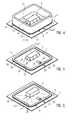
- An embodiment of the invention is explained in greater detail on the basis of a drawing. The drawing shows in:
- Fig. 1
- a perspective view of an application frame for applying a film to a plastic work piece according to an embodiment of the method according to the invention,
- Fig. 2
- a perspective view of the application frame from
Fig. 1 , wherein a film is affixed to the frame edge and covers the frame opening, - Fig. 3
- a perspective view of the application frame from
Fig. 2 , wherein an evacuation port in the form of the tube has been affixed to the film, - Fig. 4
- a perspective view of the application frame from
Fig. 3 , wherein the application frame is placed over a plastic work piece, which is disposed on a base member, so that the film fits against the plastic work piece and an adhesive joint is produced between a lip region of the film and a free region of the surface of the base member, - Fig. 5
- a perspective view of the plastic work piece from
Fig. 4 , which is covered by a film, wherein the application frame has been removed from the film, and - Fig. 6
- a perspective view of the plastic work piece from
Fig. 5 , which is covered by a film, wherein the space between the film, the plastic work piece and the base member is evacuated. -
Figs. 1 through 6 depict individual steps of an embodiment of the method according to the invention for applying a film 1 to aplastic work piece 3 that is to be cured in an autoclave. The method comprises the following steps. - An uncured
plastic work piece 3, in the present embodiment a work piece made of carbon fiber reinforced plastic from the aircraft manufacturing sector, is initially provided as depicted inFigures 4 through 6 , which work piece is to be cured in an autoclave. As can also be seen inFigs. 4 through 6 , thisplastic work piece 3 is disposed on thesurface 5 of a base member 7, which, in the present case, is a production device for the shaping of theplastic work piece 3, wherein afree region 9 of thesurface 5 of the base member 7 remains around theplastic work piece 3, which is not covered by theplastic work piece 3. - Next, an
application frame 11, as depicted inFig. 1 , is provided. Theapplication frame 11 has aframe housing 13, which in the present case, has a tubular design or, respectively, an annular design, and which has aframe opening 15 as well as aframe edge 17 enclosing theframe opening 15. As can be seen inFig. 4 , theframe opening 15 is dimensioned in such a way that theplastic work piece 3 can be passed through theframe opening 15. In so doing, theframe opening 15 is adapted to the shape of theplastic work piece 3 in such a way that, when theplastic work piece 3 is passed through theframe opening 15, aslight gap 18, having an essentially uniform width, is provided between the outer circumference of theplastic work piece 3 and theframe edge 17. - Finally, a film 1 is then provided, which is suitable for covering the
plastic work piece 3 during the curing thereof in an autoclave, as shown inFigs. 2 and4 , for example. The film 1 is designed such that it is elastically deformable, which is to say, in the case of a deformation up to a specific maximum deformation threshold, said film again assumes an initial shape after it is no longer loaded, without a further application of force. - As depicted in
Fig. 2 , the film 1 is now applied to theframe edge 17, so that theframe opening 15 is covered by the film 1. In so doing, the film 1 is pulled taught, so that it covers the frame opening 15 as smoothly as possible and without the formation of wrinkles. Alip region 19 of the film 1, which is to say, the region of the film 1, which fits against theframe edge 17, is now affixed to theframe edge 17 with the aid of an adhesive 21, in particular a strip of sealant 23, which has previously been applied to theframe edge 17. In order to affix thelip region 19 of the film 1 to theframe edge 17, instead of a strip of sealant 23, another adhesive 21, a vacuum created between thelip region 19 and theframe edge 17, an electrostatic field generated between thelip region 19 and theframe edge 17 or a mechanical fastening means, for example such a as clamp, may be used. After the film 1 has been affixed to theframe edge 17, an adhesive 21, in the present case, a strip of sealant 23, is applied to thelip region 19 of the film 1 on the side facing away from theframe edge 17. - As can be seen in
Fig. 3 , in order to evacuate thespace 25 between the film 1, theplastic work piece 3 and the base member 7 then, which is to say, before the positioning of theframe edge 17, having thelip region 19 of the film 1 affixed thereto, on thefree region 9 of thesurface 5 of the base member 7, anevacuation port 29 in the form of a tube is affixed to theupper side 27 of the film 1, which is to say, in the present case, said port is glued to the film 1 and held between two strips of sealant 23 on theframe edge 17. Theevacuation port 29 thus extends from theupper side 27 of the film 1 above theframe edge 17, so that, after the application of the film 1 onto theplastic work piece 3 or, respectively, the base member 7, this evacuation port is located between thelip region 19 of the film 1 and thefree region 9 of thesurface 5 of the base member 7 and thus, connects thespace 25 between the film 1, theplastic work piece 3 and the base member 7 to theenvironment 31. After applying the film 1, a vacuum pump is connected to theend 33 of theevacuation port 29, which is exposed to theenvironment 31, in order to evacuate thespace 25 beneath the film 1. Alternatively, theevacuation port 29 may also be provided in the base member 7 in such a way that said evacuation port connects thespace 25 between the film 1, theplastic work piece 3 and the base member 7 to theenvironment 31, or, respectively, to a vacuum pump. - As is shown in
Fig. 4 , theapplication frame 11 is finally moved with respect toplastic work piece 3, which is to say, in the present case, the application frame is placed over said work piece. In so doing, theplastic work piece 3 is passed through theframe opening 15, until theframe edge 17, having thelip region 19 of the film 1 affixed thereto, is positioned on thefree region 9 of thesurface 5 of the base member 7 about theplastic work piece 3. During this relative movement, the film 1 is elastically deformed by theplastic work piece 3 and is in contact therewith. - After the positioning of the
frame edge 17 or, respectively, of thelip region 19 of the film 1, having the strip of sealant 23 affixed thereto, on thefree region 9 of thesurface 5 of the base member 7, an adhesive joint 35 is produced between thelip region 19 of the film 1 and saidfree region 9 of thesurface 5 of the base member 7 by the strip of sealant 23, which is applied to thelip region 19 of the film 1. An air-tight adhesive joint 35 can be produced using a strip of sealant 23 of this kind, which joint is needed in order to be able to evacuate thespace 25 under the film 1. Alternatively, however, insofar as the film 1 is suited to this purpose, an adhesive joint 35 of this kind may also be produced solely by the vacuum, which is to say, the vacuum under the film 1. - After the adhesive joint 35 has been produced between the
lip region 19 of the film 1 and thefree region 9 of thesurface 5 of the base member 7, theapplication frame 11 is removed from the film 1, as is depicted inFig. 5 , wherein theplastic work piece 3, which is affixed to the base member 7 and overlaid with film 1, remains for further treatment. - In order to fit the film 1 even more tightly against the
plastic work piece 3 and the base member 7 and, in this way, in order to remove all wrinkles in the film 1 and also increase the adhesive force between the film 1 and theplastic work piece 3 or, respectively, the base member 7, in the following, thespace 25 between the film 1, theplastic work piece 3 and the base member 7 is evacuated. This evacuation takes place via theevacuation port 29, for example by connecting said port to a vacuum pump. - Once the evacuation of the
space 25 between the film 1, theplastic work piece 3 and the base member 7 has been completed and theevacuation port 29 has been sealed in order to maintain the vacuum, theplastic work piece 3, which is affixed to the base member 7 and overlaid with film 1, is placed in an autoclave for a curing treatment, in order to finally obtain a curedplastic work piece 3. - A system 37 according to the invention for applying a film 1 to a
plastic work piece 3 that is to be cured in an autoclave can be formed by anapplication frame 11, a film 1 and a base member 7, as these have been described above in conjunction with the method. Theapplication frame 11 has aframe housing 13 having aframe opening 15 and aframe edge 17 enclosing theframe opening 15, wherein theframe opening 15 is dimensioned in such a way that aplastic work piece 3, on which the film 1 is to be applied, can be passed through theframe opening 15. The film 1 is suitable for covering aplastic work piece 3, on which the film 1 is to be applied, during the curing of theplastic work piece 3 in an autoclave, wherein the film 1 is formed such that it is elastically deformable. The base member 7 is adapted in such a way that aplastic work piece 3, on which the film 1 is to be applied, is accommodated on thesurface 5 of said base member in such a way that afree region 9 of thesurface 5 of the base member 7 remains around theplastic work piece 3. Anevacuation port 29 is provided in the base member 7, which port connects thespace 25 in front of or, respectively, across from thefree region 9 of thesurface 5 of the base member 7 to a connection for a vacuum pump.
Claims (12)
- A method for applying a film (1) to a plastic work piece (3) that is to be cured, comprising the following steps:(a) providing an uncured plastic work piece (3), which is to be cured, and which is disposed on the surface (5) of a base member (7) in such a way that a free region (9) of the surface (5) of the base member (7) remains around the plastic work piece (3),(b) providing an application frame (11) having a frame housing (13), wherein the frame housing (13) has a frame opening (15) and a frame edge (17) surrounding the frame opening (15), wherein the frame opening (15) is dimensioned in such a way that the plastic work piece (3) can be passed through the frame opening (15),(c) providing a film (1), which is suitable for covering a plastic work piece (3) during the curing thereof,(d) applying the film (1) on the frame edge (17), so that the frame opening (15) is covered by the film (1), and the fastening of a lip region (19) of the film (1) to the frame edge (17), and(e) moving the application frame (11) relative to the plastic work piece (3), so that the plastic work piece (3) is passed through the frame opening (15) until the frame edge (17), having the lip region (19) of the film (1) attached thereto, contacts the free region (9) of the surface (5) of the base member (7) around the plastic work piece (3), wherein during this relative movement, the film is deformed by the plastic work piece (3) and rests against this plastic work piece (3).
- The method according to Claim 1, wherein an adhesive joint (35) is produced between the lip region (19) of the film (1) and the free region (9) of the surface (5) of the base member (7), which is contacted by the lip region (19).
- The method according to Claim 2, wherein the adhesive joint (35) is produced with the aid of an adhesive (21), which is applied to the lip region (19) of the film (1) before said lip region (19) contacts the free region (9) of the surface (5) of the base member (7) around the plastic work piece (3).
- The method according to Claim 2, wherein the adhesive joint (35) is produced with the aid of a vacuum between the lip region (19) of the film (1) and the free region (9) of the surface (5) of the base member (7), with which the lip region (19) is in contact.
- The method according to any of the Claims 2 to 4, wherein, after the adhesive joint (35) has been produced, the application frame (11) is removed from the film (1).
- The method according to any of the Claims 1 to 5, wherein, after the frame edge (17), having the lip region (19) of the film (1) affixed thereto, has contacted the free region (9) of the surface (5) of the base member (7), the space (25) between the film (1), the plastic work piece (3) and the base member (7) is evacuated.
- The method according to Claim 6, wherein, in order to evacuate the space (25) between the film (1), the plastic work piece (3) and the base member (7), an evacuation port (29) is provided in the base member (1), which connects the space (25) between the film (1), the plastic work piece (3) and the base member (7) to the environment (31), and which can be connected to a vacuum pump.
- The method according to Claim 6, wherein, in order to evacuate the space (25) between the film (1), the plastic work piece (3) and the base member (7), before the frame edge (17), having the lip region (19) of the film (1) affixed thereto, contacts the free region (9) of the surface (5) of the base member (7), an evacuation port (29) is inserted between said lip region (19) of the film (1) and the free region (9) of the surface (5) of the base member (7), which connects the space (25) between the film (1), the plastic work piece (3) and the base member (7) to the environment (31), and which can be connected to a vacuum pump.
- The method according to any of the Claims 1 to 8, wherein the lip region (19) of the film (1) is affixed to the frame edge (17) with the aid of an adhesive (21), a vacuum between the lip region (19) and the frame edge (17), an electrostatic field, which is generated between the lip region (19) and the frame edge (17), or a mechanical fastening means.
- The method according to any of the Claims 1 to 9, wherein the application frame (11) is formed in such a way that the frame opening (15) is adapted to the shape of the plastic work piece (3), wherein a gap (18) is provided when the plastic work piece (3) is passed through the frame opening (15), between the outer circumference of the plastic work piece (3) and the frame edge (17).
- A method for producing a plastic work piece (3) comprising the following steps:- applying of a film (1) to a plastic work piece (3) according to any of the Claims 1 to 10,- curing of the plastic work piece (3), which is overlaid with film (1).
- A system for applying a film (1) to a plastic work piece (3) that is to be cured, the system comprising
an application frame (11) having a frame housing (13), wherein the frame housing (13) has a frame opening (15) and a frame edge (17) surrounding the frame opening (15), wherein the frame opening (15) is dimensioned in such a way that a plastic work piece (3), on which the film (1) is to be applied, can be passed through the frame opening (15),
a film (1), which is suitable for covering a plastic work piece (3), on which the film (3) is to be applied, during the curing thereof, wherein the film (1) is formed such that it is elastically deformable, and
a base member (7), which is adapted in such a way that a plastic work piece (3), on which the film (1) is to be applied, can be accommodated on the surface (5) of said base member in such a way that a free region (9) of the surface (5) of the base member (7) remains around the plastic work piece (3),
wherein an evacuation port (29) is provided in the base member (7), said evacuation port connecting the space (25) in front of the free region (9) of the surface (5) of the base member (7) to a connection for a vacuum pump.
Applications Claiming Priority (1)
| Application Number | Priority Date | Filing Date | Title |
|---|---|---|---|
| DE102014106319.8A DE102014106319A1 (en) | 2014-05-06 | 2014-05-06 | Method and system for applying a film to a provided for curing plastic workpiece and method for producing a plastic workpiece |
Publications (2)
| Publication Number | Publication Date |
|---|---|
| EP2942182A1 true EP2942182A1 (en) | 2015-11-11 |
| EP2942182B1 EP2942182B1 (en) | 2017-02-08 |
Family
ID=53008371
Family Applications (1)
| Application Number | Title | Priority Date | Filing Date |
|---|---|---|---|
| EP15165460.5A Active EP2942182B1 (en) | 2014-05-06 | 2015-04-28 | Method and system for applying a film to a plastic work piece that is to be cured, and a method for producing a plastic work piece |
Country Status (3)
| Country | Link |
|---|---|
| US (1) | US10343384B2 (en) |
| EP (1) | EP2942182B1 (en) |
| DE (1) | DE102014106319A1 (en) |
Cited By (1)
| Publication number | Priority date | Publication date | Assignee | Title |
|---|---|---|---|---|
| US10343384B2 (en) | 2014-05-06 | 2019-07-09 | Airbus Operations Gmbh | Method and system for applying a film to a plastic work piece that is to be cured, and a method for producing a plastic work piece |
Families Citing this family (1)
| Publication number | Priority date | Publication date | Assignee | Title |
|---|---|---|---|---|
| DE102018125716A1 (en) * | 2018-10-17 | 2020-04-23 | Bayerische Motoren Werke Aktiengesellschaft | Device and method for producing a plastic component |
Citations (4)
| Publication number | Priority date | Publication date | Assignee | Title |
|---|---|---|---|---|
| GB2073648A (en) * | 1980-04-11 | 1981-10-21 | Aerovac Systems Keighley Ltd | Vacuum bagging |
| DE19505523A1 (en) * | 1995-02-18 | 1996-08-22 | Philippine Tech Kunststoff | Bonding flat sheet uniformly to base layer forming e.g. fabric-covered car trim panel |
| WO1998000275A1 (en) * | 1996-07-01 | 1998-01-08 | Magna Lomason Corporation | Method for bonding a cover to a flexible pad |
| EP1721733A1 (en) * | 2004-03-03 | 2006-11-15 | Mitsubishi Denki Kabushiki Kaisha | Decorative member and process for producing the same |
Family Cites Families (14)
| Publication number | Priority date | Publication date | Assignee | Title |
|---|---|---|---|---|
| US2073648A (en) * | 1931-09-28 | 1937-03-16 | Crown Cork & Seal Co | Container sealing composition |
| US3149018A (en) * | 1960-01-29 | 1964-09-15 | United States Gypsum Co | Film-covered article and method of making same |
| US3334383A (en) * | 1965-11-03 | 1967-08-08 | Lockheed Aircraft Corp | Molding apparatus |
| US4447282A (en) * | 1982-06-21 | 1984-05-08 | Savorgnan Valerio | Process and equipment for veneer press to glue a thin layer on a variously shaped panel surface |
| US4878979A (en) * | 1986-04-25 | 1989-11-07 | United Technologies Corporation | Method of reusably sealing a silicone rubber vacuum bag to a mold for composite manufacture |
| EP0262748A3 (en) * | 1986-09-29 | 1988-08-31 | Rita Diekwisch | Method and apparatus for covering three-dimensional objects with plastic material |
| EP0330972A3 (en) * | 1988-02-29 | 1991-09-18 | Siemens Nixdorf Informationssysteme Aktiengesellschaft | Autoclave laminating device for multilayered ciruit boards |
| FR2629010B1 (en) * | 1988-03-22 | 1990-07-20 | Aerospatiale | SEALING DEVICE FOR THE POLYMERIZATION OF A SHAPED WORKPIECE AND METHOD FOR MANUFACTURING SUCH A WORKPIECE |
| US5344687A (en) * | 1991-09-27 | 1994-09-06 | Brunswick Technologies, Inc. | Structurally reinforced thermoplastic-fabric composite construction materials that are moldable |
| GB0014113D0 (en) * | 2000-06-10 | 2000-08-02 | Gkn Westland Helicopters Ltd | Improvements in or relating to moulding |
| DE102010047346B4 (en) * | 2010-10-02 | 2015-02-05 | Premium Aerotec Gmbh | Method for creating a vacuum structure for the production of a fiber composite component |
| WO2012101793A1 (en) * | 2011-01-27 | 2012-08-02 | トヨタ自動車株式会社 | Fiber-reinforced resin material and method for producing same |
| US20130030946A1 (en) * | 2011-07-29 | 2013-01-31 | Flexi Usa, Inc. | Creation of Customized Objects for Pet Products Purchased In-Store and/or Online |
| DE102014106319A1 (en) | 2014-05-06 | 2015-11-12 | Airbus Operations Gmbh | Method and system for applying a film to a provided for curing plastic workpiece and method for producing a plastic workpiece |
-
2014
- 2014-05-06 DE DE102014106319.8A patent/DE102014106319A1/en not_active Withdrawn
-
2015
- 2015-04-28 EP EP15165460.5A patent/EP2942182B1/en active Active
- 2015-05-05 US US14/704,380 patent/US10343384B2/en active Active
Patent Citations (4)
| Publication number | Priority date | Publication date | Assignee | Title |
|---|---|---|---|---|
| GB2073648A (en) * | 1980-04-11 | 1981-10-21 | Aerovac Systems Keighley Ltd | Vacuum bagging |
| DE19505523A1 (en) * | 1995-02-18 | 1996-08-22 | Philippine Tech Kunststoff | Bonding flat sheet uniformly to base layer forming e.g. fabric-covered car trim panel |
| WO1998000275A1 (en) * | 1996-07-01 | 1998-01-08 | Magna Lomason Corporation | Method for bonding a cover to a flexible pad |
| EP1721733A1 (en) * | 2004-03-03 | 2006-11-15 | Mitsubishi Denki Kabushiki Kaisha | Decorative member and process for producing the same |
Cited By (1)
| Publication number | Priority date | Publication date | Assignee | Title |
|---|---|---|---|---|
| US10343384B2 (en) | 2014-05-06 | 2019-07-09 | Airbus Operations Gmbh | Method and system for applying a film to a plastic work piece that is to be cured, and a method for producing a plastic work piece |
Also Published As
| Publication number | Publication date |
|---|---|
| EP2942182B1 (en) | 2017-02-08 |
| US20150321458A1 (en) | 2015-11-12 |
| US10343384B2 (en) | 2019-07-09 |
| DE102014106319A1 (en) | 2015-11-12 |
Similar Documents
| Publication | Publication Date | Title |
|---|---|---|
| EP1162055B1 (en) | Vacuum membrane moulding of a layered composite material | |
| US8628639B2 (en) | Vacuum bag processing using dual seals | |
| KR101961490B1 (en) | Integrally stiffened, reusable vacuum bag and method of making the same | |
| JP7001338B2 (en) | Fastener sealing system | |
| CN101484301B (en) | Method for manufacturing fiber composite parts for aviation and spaceflight | |
| CN106414031B (en) | Apparatus and method for forming a flange | |
| JP6722369B2 (en) | Method for forming honeycomb sandwich composite | |
| US10456961B2 (en) | Bonding apparatus and bonding method | |
| KR20170044027A (en) | Method of curing a composite article using differential vacuum | |
| EP3750698A1 (en) | Repair patch, repair patch molding method, and repair method for composite material | |
| EP2942182B1 (en) | Method and system for applying a film to a plastic work piece that is to be cured, and a method for producing a plastic work piece | |
| US10639857B1 (en) | Magnetic compaction blanket for composite structure curing | |
| WO2016137565A1 (en) | Composite repair method | |
| WO2020123298A3 (en) | Screen protector application system and method | |
| US20200023593A1 (en) | Method of manufacturing hollow composite structure | |
| EP3274145B1 (en) | Processes for manufacturing parts employing additive manufacturing | |
| US10675821B2 (en) | Installation tool and associated method for applying a patch to a surface | |
| US10000019B2 (en) | Installation assembly and associated method for forming a bonded joint | |
| US9579855B2 (en) | Secondary groove for work piece retention during machining | |
| KR102577575B1 (en) | Methods and systems for bonding composite structures | |
| US11660829B2 (en) | Method of seamlessly bagging composite parts | |
| US8439663B2 (en) | De-mold liner based injection tool | |
| GB2073648A (en) | Vacuum bagging | |
| JP2015155197A (en) | Joint molding | |
| US11718050B2 (en) | Systems and methods for adhesive-injected patch repair |
Legal Events
| Date | Code | Title | Description |
|---|---|---|---|
| PUAI | Public reference made under article 153(3) epc to a published international application that has entered the european phase |
Free format text: ORIGINAL CODE: 0009012 |
|
| AK | Designated contracting states |
Kind code of ref document: A1 Designated state(s): AL AT BE BG CH CY CZ DE DK EE ES FI FR GB GR HR HU IE IS IT LI LT LU LV MC MK MT NL NO PL PT RO RS SE SI SK SM TR |
|
| AX | Request for extension of the european patent |
Extension state: BA ME |
|
| 17P | Request for examination filed |
Effective date: 20160511 |
|
| RBV | Designated contracting states (corrected) |
Designated state(s): AL AT BE BG CH CY CZ DE DK EE ES FI FR GB GR HR HU IE IS IT LI LT LU LV MC MK MT NL NO PL PT RO RS SE SI SK SM TR |
|
| GRAP | Despatch of communication of intention to grant a patent |
Free format text: ORIGINAL CODE: EPIDOSNIGR1 |
|
| INTG | Intention to grant announced |
Effective date: 20160823 |
|
| GRAS | Grant fee paid |
Free format text: ORIGINAL CODE: EPIDOSNIGR3 |
|
| GRAA | (expected) grant |
Free format text: ORIGINAL CODE: 0009210 |
|
| AK | Designated contracting states |
Kind code of ref document: B1 Designated state(s): AL AT BE BG CH CY CZ DE DK EE ES FI FR GB GR HR HU IE IS IT LI LT LU LV MC MK MT NL NO PL PT RO RS SE SI SK SM TR |
|
| REG | Reference to a national code |
Ref country code: GB Ref legal event code: FG4D |
|
| REG | Reference to a national code |
Ref country code: CH Ref legal event code: EP Ref country code: AT Ref legal event code: REF Ref document number: 866671 Country of ref document: AT Kind code of ref document: T Effective date: 20170215 |
|
| REG | Reference to a national code |
Ref country code: IE Ref legal event code: FG4D |
|
| REG | Reference to a national code |
Ref country code: DE Ref legal event code: R096 Ref document number: 602015001466 Country of ref document: DE |
|
| REG | Reference to a national code |
Ref country code: FR Ref legal event code: PLFP Year of fee payment: 3 |
|
| REG | Reference to a national code |
Ref country code: LT Ref legal event code: MG4D |
|
| REG | Reference to a national code |
Ref country code: NL Ref legal event code: MP Effective date: 20170208 |
|
| REG | Reference to a national code |
Ref country code: AT Ref legal event code: MK05 Ref document number: 866671 Country of ref document: AT Kind code of ref document: T Effective date: 20170208 |
|
| PG25 | Lapsed in a contracting state [announced via postgrant information from national office to epo] |
Ref country code: FI Free format text: LAPSE BECAUSE OF FAILURE TO SUBMIT A TRANSLATION OF THE DESCRIPTION OR TO PAY THE FEE WITHIN THE PRESCRIBED TIME-LIMIT Effective date: 20170208 Ref country code: GR Free format text: LAPSE BECAUSE OF FAILURE TO SUBMIT A TRANSLATION OF THE DESCRIPTION OR TO PAY THE FEE WITHIN THE PRESCRIBED TIME-LIMIT Effective date: 20170509 Ref country code: NO Free format text: LAPSE BECAUSE OF FAILURE TO SUBMIT A TRANSLATION OF THE DESCRIPTION OR TO PAY THE FEE WITHIN THE PRESCRIBED TIME-LIMIT Effective date: 20170508 Ref country code: HR Free format text: LAPSE BECAUSE OF FAILURE TO SUBMIT A TRANSLATION OF THE DESCRIPTION OR TO PAY THE FEE WITHIN THE PRESCRIBED TIME-LIMIT Effective date: 20170208 Ref country code: LT Free format text: LAPSE BECAUSE OF FAILURE TO SUBMIT A TRANSLATION OF THE DESCRIPTION OR TO PAY THE FEE WITHIN THE PRESCRIBED TIME-LIMIT Effective date: 20170208 |
|
| PG25 | Lapsed in a contracting state [announced via postgrant information from national office to epo] |
Ref country code: LV Free format text: LAPSE BECAUSE OF FAILURE TO SUBMIT A TRANSLATION OF THE DESCRIPTION OR TO PAY THE FEE WITHIN THE PRESCRIBED TIME-LIMIT Effective date: 20170208 Ref country code: BG Free format text: LAPSE BECAUSE OF FAILURE TO SUBMIT A TRANSLATION OF THE DESCRIPTION OR TO PAY THE FEE WITHIN THE PRESCRIBED TIME-LIMIT Effective date: 20170508 Ref country code: AT Free format text: LAPSE BECAUSE OF FAILURE TO SUBMIT A TRANSLATION OF THE DESCRIPTION OR TO PAY THE FEE WITHIN THE PRESCRIBED TIME-LIMIT Effective date: 20170208 Ref country code: PT Free format text: LAPSE BECAUSE OF FAILURE TO SUBMIT A TRANSLATION OF THE DESCRIPTION OR TO PAY THE FEE WITHIN THE PRESCRIBED TIME-LIMIT Effective date: 20170608 Ref country code: SE Free format text: LAPSE BECAUSE OF FAILURE TO SUBMIT A TRANSLATION OF THE DESCRIPTION OR TO PAY THE FEE WITHIN THE PRESCRIBED TIME-LIMIT Effective date: 20170208 Ref country code: NL Free format text: LAPSE BECAUSE OF NON-PAYMENT OF DUE FEES Effective date: 20170208 Ref country code: ES Free format text: LAPSE BECAUSE OF FAILURE TO SUBMIT A TRANSLATION OF THE DESCRIPTION OR TO PAY THE FEE WITHIN THE PRESCRIBED TIME-LIMIT Effective date: 20170208 Ref country code: RS Free format text: LAPSE BECAUSE OF FAILURE TO SUBMIT A TRANSLATION OF THE DESCRIPTION OR TO PAY THE FEE WITHIN THE PRESCRIBED TIME-LIMIT Effective date: 20170208 |
|
| PG25 | Lapsed in a contracting state [announced via postgrant information from national office to epo] |
Ref country code: IT Free format text: LAPSE BECAUSE OF FAILURE TO SUBMIT A TRANSLATION OF THE DESCRIPTION OR TO PAY THE FEE WITHIN THE PRESCRIBED TIME-LIMIT Effective date: 20170208 Ref country code: SK Free format text: LAPSE BECAUSE OF FAILURE TO SUBMIT A TRANSLATION OF THE DESCRIPTION OR TO PAY THE FEE WITHIN THE PRESCRIBED TIME-LIMIT Effective date: 20170208 Ref country code: RO Free format text: LAPSE BECAUSE OF FAILURE TO SUBMIT A TRANSLATION OF THE DESCRIPTION OR TO PAY THE FEE WITHIN THE PRESCRIBED TIME-LIMIT Effective date: 20170208 Ref country code: CZ Free format text: LAPSE BECAUSE OF FAILURE TO SUBMIT A TRANSLATION OF THE DESCRIPTION OR TO PAY THE FEE WITHIN THE PRESCRIBED TIME-LIMIT Effective date: 20170208 Ref country code: EE Free format text: LAPSE BECAUSE OF FAILURE TO SUBMIT A TRANSLATION OF THE DESCRIPTION OR TO PAY THE FEE WITHIN THE PRESCRIBED TIME-LIMIT Effective date: 20170208 |
|
| REG | Reference to a national code |
Ref country code: DE Ref legal event code: R097 Ref document number: 602015001466 Country of ref document: DE |
|
| PG25 | Lapsed in a contracting state [announced via postgrant information from national office to epo] |
Ref country code: SM Free format text: LAPSE BECAUSE OF FAILURE TO SUBMIT A TRANSLATION OF THE DESCRIPTION OR TO PAY THE FEE WITHIN THE PRESCRIBED TIME-LIMIT Effective date: 20170208 Ref country code: DK Free format text: LAPSE BECAUSE OF FAILURE TO SUBMIT A TRANSLATION OF THE DESCRIPTION OR TO PAY THE FEE WITHIN THE PRESCRIBED TIME-LIMIT Effective date: 20170208 Ref country code: PL Free format text: LAPSE BECAUSE OF FAILURE TO SUBMIT A TRANSLATION OF THE DESCRIPTION OR TO PAY THE FEE WITHIN THE PRESCRIBED TIME-LIMIT Effective date: 20170208 |
|
| PLBE | No opposition filed within time limit |
Free format text: ORIGINAL CODE: 0009261 |
|
| STAA | Information on the status of an ep patent application or granted ep patent |
Free format text: STATUS: NO OPPOSITION FILED WITHIN TIME LIMIT |
|
| 26N | No opposition filed |
Effective date: 20171109 |
|
| REG | Reference to a national code |
Ref country code: IE Ref legal event code: MM4A |
|
| PG25 | Lapsed in a contracting state [announced via postgrant information from national office to epo] |
Ref country code: MC Free format text: LAPSE BECAUSE OF FAILURE TO SUBMIT A TRANSLATION OF THE DESCRIPTION OR TO PAY THE FEE WITHIN THE PRESCRIBED TIME-LIMIT Effective date: 20170208 |
|
| PG25 | Lapsed in a contracting state [announced via postgrant information from national office to epo] |
Ref country code: LU Free format text: LAPSE BECAUSE OF NON-PAYMENT OF DUE FEES Effective date: 20170428 Ref country code: SI Free format text: LAPSE BECAUSE OF FAILURE TO SUBMIT A TRANSLATION OF THE DESCRIPTION OR TO PAY THE FEE WITHIN THE PRESCRIBED TIME-LIMIT Effective date: 20170208 |
|
| REG | Reference to a national code |
Ref country code: BE Ref legal event code: MM Effective date: 20170430 |
|
| REG | Reference to a national code |
Ref country code: FR Ref legal event code: PLFP Year of fee payment: 4 |
|
| PG25 | Lapsed in a contracting state [announced via postgrant information from national office to epo] |
Ref country code: IE Free format text: LAPSE BECAUSE OF NON-PAYMENT OF DUE FEES Effective date: 20170428 |
|
| PG25 | Lapsed in a contracting state [announced via postgrant information from national office to epo] |
Ref country code: BE Free format text: LAPSE BECAUSE OF NON-PAYMENT OF DUE FEES Effective date: 20170430 |
|
| PG25 | Lapsed in a contracting state [announced via postgrant information from national office to epo] |
Ref country code: MT Free format text: LAPSE BECAUSE OF NON-PAYMENT OF DUE FEES Effective date: 20170428 |
|
| REG | Reference to a national code |
Ref country code: CH Ref legal event code: PL |
|
| PG25 | Lapsed in a contracting state [announced via postgrant information from national office to epo] |
Ref country code: LI Free format text: LAPSE BECAUSE OF NON-PAYMENT OF DUE FEES Effective date: 20180430 Ref country code: CH Free format text: LAPSE BECAUSE OF NON-PAYMENT OF DUE FEES Effective date: 20180430 |
|
| PG25 | Lapsed in a contracting state [announced via postgrant information from national office to epo] |
Ref country code: HU Free format text: LAPSE BECAUSE OF FAILURE TO SUBMIT A TRANSLATION OF THE DESCRIPTION OR TO PAY THE FEE WITHIN THE PRESCRIBED TIME-LIMIT; INVALID AB INITIO Effective date: 20150428 |
|
| PG25 | Lapsed in a contracting state [announced via postgrant information from national office to epo] |
Ref country code: CY Free format text: LAPSE BECAUSE OF FAILURE TO SUBMIT A TRANSLATION OF THE DESCRIPTION OR TO PAY THE FEE WITHIN THE PRESCRIBED TIME-LIMIT Effective date: 20170208 |
|
| PG25 | Lapsed in a contracting state [announced via postgrant information from national office to epo] |
Ref country code: MK Free format text: LAPSE BECAUSE OF FAILURE TO SUBMIT A TRANSLATION OF THE DESCRIPTION OR TO PAY THE FEE WITHIN THE PRESCRIBED TIME-LIMIT Effective date: 20170208 |
|
| PG25 | Lapsed in a contracting state [announced via postgrant information from national office to epo] |
Ref country code: TR Free format text: LAPSE BECAUSE OF FAILURE TO SUBMIT A TRANSLATION OF THE DESCRIPTION OR TO PAY THE FEE WITHIN THE PRESCRIBED TIME-LIMIT Effective date: 20170208 |
|
| PG25 | Lapsed in a contracting state [announced via postgrant information from national office to epo] |
Ref country code: AL Free format text: LAPSE BECAUSE OF FAILURE TO SUBMIT A TRANSLATION OF THE DESCRIPTION OR TO PAY THE FEE WITHIN THE PRESCRIBED TIME-LIMIT Effective date: 20170208 Ref country code: IS Free format text: LAPSE BECAUSE OF FAILURE TO SUBMIT A TRANSLATION OF THE DESCRIPTION OR TO PAY THE FEE WITHIN THE PRESCRIBED TIME-LIMIT Effective date: 20170608 |
|
| PGFP | Annual fee paid to national office [announced via postgrant information from national office to epo] |
Ref country code: DE Payment date: 20250422 Year of fee payment: 11 |
|
| PGFP | Annual fee paid to national office [announced via postgrant information from national office to epo] |
Ref country code: GB Payment date: 20250423 Year of fee payment: 11 |
|
| PGFP | Annual fee paid to national office [announced via postgrant information from national office to epo] |
Ref country code: FR Payment date: 20250425 Year of fee payment: 11 |