EP2942077A1 - Mounting card - Google Patents
Mounting card Download PDFInfo
- Publication number
- EP2942077A1 EP2942077A1 EP15162879.9A EP15162879A EP2942077A1 EP 2942077 A1 EP2942077 A1 EP 2942077A1 EP 15162879 A EP15162879 A EP 15162879A EP 2942077 A1 EP2942077 A1 EP 2942077A1
- Authority
- EP
- European Patent Office
- Prior art keywords
- distal
- proximal
- flexible medical
- medical component
- tab
- Prior art date
- Legal status (The legal status is an assumption and is not a legal conclusion. Google has not performed a legal analysis and makes no representation as to the accuracy of the status listed.)
- Granted
Links
Images


Classifications
-
- A—HUMAN NECESSITIES
- A61—MEDICAL OR VETERINARY SCIENCE; HYGIENE
- A61M—DEVICES FOR INTRODUCING MEDIA INTO, OR ONTO, THE BODY; DEVICES FOR TRANSDUCING BODY MEDIA OR FOR TAKING MEDIA FROM THE BODY; DEVICES FOR PRODUCING OR ENDING SLEEP OR STUPOR
- A61M25/00—Catheters; Hollow probes
- A61M25/002—Packages specially adapted therefor ; catheter kit packages
-
- B—PERFORMING OPERATIONS; TRANSPORTING
- B65—CONVEYING; PACKING; STORING; HANDLING THIN OR FILAMENTARY MATERIAL
- B65D—CONTAINERS FOR STORAGE OR TRANSPORT OF ARTICLES OR MATERIALS, e.g. BAGS, BARRELS, BOTTLES, BOXES, CANS, CARTONS, CRATES, DRUMS, JARS, TANKS, HOPPERS, FORWARDING CONTAINERS; ACCESSORIES, CLOSURES, OR FITTINGS THEREFOR; PACKAGING ELEMENTS; PACKAGES
- B65D73/00—Packages comprising articles attached to cards, sheets or webs
- B65D73/0007—Packages comprising articles attached to cards, sheets or webs the articles being attached to the plane surface of a single card
- B65D73/0014—Packages comprising articles attached to cards, sheets or webs the articles being attached to the plane surface of a single card by means of separate fixing elements, e.g. clips, clamps, bands
Definitions
- the present invention relates to a mounting card.
- a flexible medical component such as a catheter is typically held on a mounting card having a flat surface and packaged in a sterile condition.
- a mounting card has a plurality of tabs for holding a flexible medical component such as a catheter.
- the tabs are formed by making cuts such as a V-shaped cut or a U-shaped cut on the mounting card.
- the tabs formed by cutting the mounting card are slightly lifted from the flat surface of the mounting card to hold the flexible medical component between the flat surface of the mounting card and the tabs.
- the flexible medical component is held thus on the mounting card. In this case, if a holding force of the tab, that is, a force for returning the tab to the flat surface is small, a force for holding the flexible medical component becomes insufficient.
- the flexible medical component is an elongated flexible medical component, in particular, the proximal side of the elongated flexible medical component often be held and then the elongated flexible medical component often be pulled out from the package when the elongated flexible medical component is got out from the package.
- a distal portion of the flexible medical component is not linear like a catheter having a curved distal portion, the distal portion of the flexible medical component may be caught by the tab and it may be responsible for deformation or breakage of the distal portion.
- Patent Literature 1 discloses a mounting card having a flat surface that holds an elongated flexible medical component, e.g., a catheter.
- the flat surface has relatively large tabs and relatively small tabs in pairs that hold the flexible medical component.
- the relatively large tabs and the relatively small tabs are formed by making triangular (U-shaped) cuts with rounded tips on the mounting card. The tabs shaped thus in pairs reduce damage of the flexible medical component when the flexible medical component is got out from the mounting card.
- Patent Literature 2 discloses a mounting card that has a flat surface for holding an elongated flexible medical component, e.g., a catheter.
- the flat surface has pairs of L-shaped or mountain-shaped tabs that hold the flexible medical component.
- the L-shaped or mountain-shaped tabs are formed by making cuts on a mounting card. A pulling resistance of the flexible medical component is reduced by cuts made on both ends of the tabs toward the distal end side of the flexible medical component.
- a mounting card that can apply to flexible medical components varying in shape has been demanded. Furthermore, a mounting card having a sufficient holding force for holding a flexible medical component and prevent deformation or breakage on the flexible medical component even in a case that the flexible medical component is pulled out from the mounting card.
- An obj ect of the present invention is to provide a mounting card having a flat surface for holding an elongated flexible medical component, the mounting card having a sufficient holding force for holding the flexible medical component and preventing deformation or breakage of the flexible medical component even if the flexible medical component is pulled out from the proximal side.
- the present invention is a mounting card having a flat surface for holding an elongated flexible medical component, wherein the flat surface comprises a U-shaped distal-side tab and a proximal-side tab that are formed in a pair so as to hold the flexible medical component on the flat surface, the distal-side tab and the proximal-side tab are formed in a pair such that the distal-side tab is located closer to the distal end side of the flexible medical component than the proximal-side tab when the flexible medical component is held on the mounting card, the distal-side tab is formed by making a U-shaped cut on the mounting card such that a tip of the distal-side tab is oriented toward the distal end side of the flexible medical component, and the proximal-side tab is formed by making a cut on the mounting card such that a distal side, which is located closer to the distal end side of the flexible medical component, of the cut of the proximal-side tab is disposed in parallel with a proximal side, which is located
- the proximal-side tab may be preferably formed by making a V-shaped cut on the mounting card.
- the mounting card of the present invention has the flat surface having the U-shaped distal-side tab and the proximal-side tab that are formed in a pair so as to hold the flexible medical component on the flat surface
- the distal-side tab is formed by making the U-shaped cut on the mounting card such that the tip of the distal-side tab is oriented toward the distal end side of the flexible medical component
- the proximal-side tab is formed by making the cut on the mounting card such that the distal side, which is located closer to the distal end side of the flexible medical component, of the cut of the proximal-side tab is disposed in parallel with the proximal side, which is located closer to the proximal end side of the flexible medical component, of the U-shaped cut of the distal-side tab and a distance between the distal side of the cut of the proximal-side tab and the proximal side of the U-shaped cut of the distal-side tab is larger than the diameter of the flexible medical component.
- the flexible medical component having a curved distal portion is held on the mounting card, the curved distal portion is not caught when the flexible medical component is pulled out from the mounting card and deformation or breakage of the flexible medical component is avoided. Furthermore, the flexible medical component is reliably held by the distal-side tab and the proximal-side tab with an excellent holding force.
- the proximal-side tab is V-shaped, the proximal-side tab has a long base on which the mounting card and the proximal-side tab are not separated from each other. This provides an excellent holding force for holding the flexible medical component without excessively increasing the size of the proximal-side tab, and a sufficient holding force for holding the flexible medical component is easily obtained.
- FIG. 1 the left side of the drawing is a distal end side of a flexible medical component held on a mounting card, and the right side of FIG. 1 is a proximal end side of the flexible medical component held on the mounting card.
- a connector or the like is connected in the proximal end side of the flexible medical component.
- FIG. 1 is a front view schematically showing a first embodiment of the mounting card of the present invention.
- FIG. 2(a) is an enlarged view of a part A of FIG. 1 .
- FIG. 2(b) is an enlarged view of a part B of FIG. 1 .
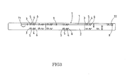
- FIG. 3 is a front view schematically showing a state in use in which the flexible medical component is held on the mounting card according to the first embodiment of the present invention.
- a mounting card 1 has a flat surface 2 on which distal-side tabs 3 and 4 and proximal-side tabs 5 and 6 are formed.
- the distal-side tabs 3 and 4 and the proximal-side tabs 5 and 6 are formed by making cuts on the mounting card 2 with a cutter and so on.
- the distal-side tabs 3 and the distal-side tabs 4 are faced toward different directions.
- the distal-side tab 3 has a tab base 31 that is not separated from the flat surface 2 and is located on the upper side of FIG. 2 (a) .
- the distal-side tab 4 has a tab base 41 that is not separated from the flat surface 2 and is located on the lower side of FIG. 2(b) .
- the proximal-side tab 5 and the proximal-side tab 6 are faced toward different directions.
- the proximal-side tab 5 has a tab base 51 that is not separated from the flat surface 2 and is located on the lower side of FIG. 2(a) .
- the proximal-side tab 6 has a tab base 61 that is not separated from the flat surface 2 and is located on the upper side of FIG. 2 (b) .
- the distal-side tabs 3 and 4 and the proximal-side tabs 5 and 6 are formed such that the distal-side tab 3 and the proximal-side tab 5 are formed in a pair so as to hold a flexible medical component 7 while the distal-side tab 4 and the proximal-side tab 6 are formed in a pair so as to hold the flexible medical component 7.
- Any one of the pairs may be formed on the flat surface 2. However, both of the pairs are preferably formed on the flat surface 2 so as to make a choice between the pairs depending on the flexible medical component 7 to be held.
- the shape and size of the mounting card 1 are not particularly limited as long as the elongated flexible medical component 7 can be held.
- the mounting card 1 is preferably a rectangular sheet which is longer than the catheter.
- the mounting card 1 is preferably sized and shaped so as to hold all of the flexible medical component 7.
- the mounting card 1 may be sized and shaped so as to hold a part of the flexible medical component 7.
- FIG. 3 shows a state in use in which the elongated flexible medical component 7, e.g., a catheter is held on the mounting card 1.
- the mounting card 1 is a rectangular sheet that can hold all of the flexible medical component 7, e.g., a catheter.
- the flexible medical component 7 is placed on the flat surface 2 and then is held between the flat surface 2 and the distal-side tab 3 and proximal-side tab 4.
- a material forming of the mounting card 1 is not particularly limited and includes any material which is used conventionally such as paper, resin, and resin foam.
- the mounting card 1 has the flat surface 2 for holding the flexible medical component 7.
- the flat surface 2 does not need to be precisely flat as long as the flexible medical component 7 can be placed on the mounting card 1.
- the distal-side tabs 3 and 4 are U-shaped with smooth tips 32 and 42 and are located closer to the distal end side than the proximal-side tabs 5 and 6 which are arranged in pairs with the distal-side tabs 3 and 4.
- the U-shape includes, as shown in FIGS. 1 to 3 , a shape of deformed alphabet U.
- the distal-side tabs 3 and 4 are formed by making U-shaped cuts on the mounting card 1 such that the tips 32 and 42 of the distal-side tabs 3 and 4 are oriented toward the distal end side.
- the state in which the tips 32 and 42 are oriented toward the distal end side means that the tips 32 and 42 are located closer to the distal end side than distal ends 311 and 411 of the tab bases 31 and 41 in the axial direction of the flexible medical component 7 to be held.
- the distal-side tabs 3 and 4 have distal sides 33 and 43, and the distal sides 33 and 43 may be linear or smoothly curved.
- the distal-side tabs 3 and 4 have proximal sides 34 and 44, and the proximal sides 34 and 44 may be linear or smoothly curved.
- the proximal sides 34 and 44 are preferably linear in view of the adjustability of a positional relationship with distal sides 53 and 63 of the proximal-side tabs 5 and 6, which will be described later.
- the distal-side tabs 3 and 4 are shaped thus, even if the flexible medical component 7 having a curved distal portion 71 is held on the mounting card 1, the flexible medical component 7 can be got out from the mounting card 1 without catch of the distal portion 71 of the flexible medical component 7 by the distal-side tabs 3 and 4. Thus, the flexible medical component 7 is not deformed or broken by the distal-side tabs 3 and 4.
- the proximal-side tabs 5 and 6 are located closer to the proximal end side than the distal-side tabs 3 and 4 that are paired with the proximal-side tabs 5 and 6, respectively.
- the proximal-side tabs are arranged such that the distal sides 53 and 63 of the proximal-side tabs 5 and 6 are disposed in parallel with the proximal sides 34 and 44 of the distal-side tabs 3 and 4. Therefore, if the proximal sides 34 and 44 of the distal-side tabs 3 and 4 are linear, the distal sides 53 and 63 of the proximal-side tabs 5 and 6 are also linear. If the proximal sides 34 and 44 of the distal-side tabs 3 and 4 are curved, the distal sides 53 and 63 of the proximal-side tabs 5 and 6 are also curved.
- proximal sides 34 and 44 of the distal-side tabs 3 and 4 and the distal sides 53 and 63 of the proximal-side tabs 5 and 6 are preferably linear because the positional relationship between the proximal sides 34 and 44 of the distal-side tabs 3 and 4 and the distal sides 53 and 63 of the proximal-side tabs 5 and 6 is easy to be adjusted.
- the proximal-side tabs 5 and 6 and the distal-side tabs 3 and 4 are formed such that the distal sides 53 and 63 of the proximal-side tabs 5 and 6 and the proximal sides 34 and 44 of the distal-side tabs 3 and 4 are disposed in parallel with each other with a distance larger than the diameter of the flexible medical component 7 to be held.
- a distance L1 between the distal side 53 of the proximal-side tab 5 and the proximal side 34 of the distal-side tab 3 and a distance L2 between the distal side 63 of the proximal-side tab 6 and the proximal side 44 of the distal-side tab 4 are set larger than the diameter of the flexible medical component 7 to be held.
- the tips 52 and 62 of the proximal-side tabs 5 and 6 may have V-shapes or smoothly curved U-shapes.
- the tip of V-shape is more preferable.
- the V-shapes of the tips 52 and 62 can provide a long length from the base 51 and 61 to the tip 52 and 62, thereby it becomes easier to hold the flexible medical component 7.
- the V-shaped tips 52 and 62 preferably have slightly rounded corners to prevent the tips 52 and 62 from sticking in an operator's hand and prevent the tips 52 and 62 from damaging, for example, the film of a package when the flexible medical component 7 is held and packaged.
- the proximal-side tabs 5 and 6 have proximal sides 54 and 64 , and the proximal sides 54 and 64 may be linear or smoothly curved.
- the proximal-side tabs 5 and 6 preferably have large surface areas and have the long tab bases 51 and 61.
- the proximal sides 54 and 64 of the proximal-side tabs 5 and 6 are preferably linear because the lengths of the tab bases 51 and 61 can be secured while keeping the large surface areas of the proximal-side tabs 5 and 6.
- proximal-side tabs 5 and 6 preferably include the linear distal sides 53 and 63, the linear proximal sides 54 and 64, and the V-shaped tips 52 and 62.
- the proximal-side tabs 5 and 6 formed thus can reliably hold the flexible medical component 7. Moreover, when the flexible medical component 7 having the curved distal portion 71 is held on the mounting card 1 and then is got out from the mounting card 1, the distal portion 71 of the flexible medical component 7 is not caught by the proximal-side tabs 5 and 6, preventing the catheter 7 from being deformed or broken by the distal-side tabs 3 and 4.
- the flat surface 2 may optionally have tabs having other shapes in addition to the distal-side tabs 3 and 4 and the proximal-side tabs 5 and 6.
- the flat surface 2 may include a tunnel-like tab 8 that has a through hole for holding a bulky connector 72 typically attached to the proximal end side of the flexible medical component 7, and a positioning tab 9 that suppress a displacement of the holding position of the flexible medical component 7 on the flat surface 2.
- the flexible medical component 7 may be a catheter, a sheath, and so on.
- the distal portion 71 of the flexible medical component 7 may be curved.
- the mounting card 1 of the present invention is suitable for holding catheters typically provided with curved distal portion.
- the elongated flexible medical component 7 is held by the tunnel-like tab 8 and the positioning tab 9 that are optionally provided; meanwhile, the distal-side tabs 3 and 4 and the proximal-side tabs 5 and 6 are lifted to hold the flexible medical component 7 between the flat surface 2 and the distal-side tabs 3 and 4 and the proximal-side tabs 5 and 6.
- the flexible medical component 7 is held thus on the flat surface 2 of the mounting card 1.
- distal-side tabs 3 and 4 and the proximal-side tabs 5 and 6 are optional and thus there is no need to use all of them.
- the flexible medical component 7 having the curved distal portion 71 is held, tabs faced toward the same direction as the curving direction of the distal portion 71 are selected from among the distal-side tabs 3 and 4 and are used.
- the flexible medical component 7 includes the distal portion 71 that is curved downward. If the flexible medical component 7 like this is held, the distal-side tabs 3 which is faced toward downward same as the curving direction of the distal portion 71 in FIG. 3 are selected and are used.
- the flexible medical component 7 having the distal portion 71 that is curved downward is held by the pairs of the distal-side tabs 3 and the proximal-side tabs 5.
- the pairs of the distal-side tabs 4 and the proximal-side tabs 6 are unused and constitute the flat surface 2 without being lifted.
- the mounting card with the flexible medical component 7 is packaged into a packaging bag according to a conventional method. After that, the flexible medical component 7 is optionally sterilized.
- the package obtained thus is opened by, for example, a doctor to get out the flexible medical component 7 from the package for the use of the flexible medical component 7.
- the flexible medical component 7 is got out, typically, the mounting card 1 with the flexible medical component 7 is got out from the packaging bag and then the flexible medical component 7 is carefully detached from the mounting card 1.
- the flexible medical component 7 since the flexible medical component 7 is long, it tends to open the packaging bag from the proximal end side of the flexible medical component 7, hold the proximal end side of the flexible medical component 7 and pull out the flexible medical component 7 from the packaging bag and the mounting card 1.
- the mounting card 1 according to the present invention has the above-described configuration, the flexible medical component is not deformed or broken even if the flexible medical component 7 is pulled out from the mounting card 1.
Landscapes
- Health & Medical Sciences (AREA)
- Life Sciences & Earth Sciences (AREA)
- Engineering & Computer Science (AREA)
- Heart & Thoracic Surgery (AREA)
- Animal Behavior & Ethology (AREA)
- Pulmonology (AREA)
- Anesthesiology (AREA)
- Biomedical Technology (AREA)
- Veterinary Medicine (AREA)
- Hematology (AREA)
- Biophysics (AREA)
- General Health & Medical Sciences (AREA)
- Public Health (AREA)
- Mechanical Engineering (AREA)
- Media Introduction/Drainage Providing Device (AREA)
- Packages (AREA)
- Infusion, Injection, And Reservoir Apparatuses (AREA)
- Medical Preparation Storing Or Oral Administration Devices (AREA)
Abstract
Description
- The present invention relates to a mounting card.
- Conventionally, a flexible medical component such as a catheter is typically held on a mounting card having a flat surface and packaged in a sterile condition. Such a mounting card has a plurality of tabs for holding a flexible medical component such as a catheter. The tabs are formed by making cuts such as a V-shaped cut or a U-shaped cut on the mounting card. The tabs formed by cutting the mounting card are slightly lifted from the flat surface of the mounting card to hold the flexible medical component between the flat surface of the mounting card and the tabs. The flexible medical component is held thus on the mounting card. In this case, if a holding force of the tab, that is, a force for returning the tab to the flat surface is small, a force for holding the flexible medical component becomes insufficient. If the holding force of the tab, that is, the force for returning the tab to the flat surface is large, another problem arises such that it becomes hard to get out the packaged flexible medical component from the package when used. If the flexible medical component is an elongated flexible medical component, in particular, the proximal side of the elongated flexible medical component often be held and then the elongated flexible medical component often be pulled out from the package when the elongated flexible medical component is got out from the package. In this case, if a distal portion of the flexible medical component is not linear like a catheter having a curved distal portion, the distal portion of the flexible medical component may be caught by the tab and it may be responsible for deformation or breakage of the distal portion.
- For example, Patent Literature 1 discloses a mounting card having a flat surface that holds an elongated flexible medical component, e.g., a catheter. The flat surface has relatively large tabs and relatively small tabs in pairs that hold the flexible medical component. The relatively large tabs and the relatively small tabs are formed by making triangular (U-shaped) cuts with rounded tips on the mounting card. The tabs shaped thus in pairs reduce damage of the flexible medical component when the flexible medical component is got out from the mounting card.
- Moreover, for example, Patent Literature 2 discloses a mounting card that has a flat surface for holding an elongated flexible medical component, e.g., a catheter. The flat surface has pairs of L-shaped or mountain-shaped tabs that hold the flexible medical component. The L-shaped or mountain-shaped tabs are formed by making cuts on a mounting card. A pulling resistance of the flexible medical component is reduced by cuts made on both ends of the tabs toward the distal end side of the flexible medical component.
- As described above, conventionally, a tab shape for a mounting card has been proposed so as to prevent damage on a flexible medical component with a small pulling resistance even in a case that the flexible medical component is pulled out.
- However, flexible medical components have various shapes and a mounting card that can apply to flexible medical components varying in shape has been demanded. Furthermore, a mounting card having a sufficient holding force for holding a flexible medical component and prevent deformation or breakage on the flexible medical component even in a case that the flexible medical component is pulled out from the mounting card.
-
- [Patent Literature 1] National Publication of Translated Version No.
2007-527295 - [Patent Literature 2] Japanese Patent Laid-Open No.
2009-201826 - An obj ect of the present invention is to provide a mounting card having a flat surface for holding an elongated flexible medical component, the mounting card having a sufficient holding force for holding the flexible medical component and preventing deformation or breakage of the flexible medical component even if the flexible medical component is pulled out from the proximal side.
- The present invention is a mounting card having a flat surface for holding an elongated flexible medical component, wherein
the flat surface comprises a U-shaped distal-side tab and a proximal-side tab that are formed in a pair so as to hold the flexible medical component on the flat surface, the distal-side tab and the proximal-side tab are formed in a pair such that the distal-side tab is located closer to the distal end side of the flexible medical component than the proximal-side tab when the flexible medical component is held on the mounting card, the distal-side tab is formed by making a U-shaped cut on the mounting card such that a tip of the distal-side tab is oriented toward the distal end side of the flexible medical component, and the proximal-side tab is formed by making a cut on the mounting card such that a distal side, which is located closer to the distal end side of the flexible medical component, of the cut of the proximal-side tab is disposed in parallel with a proximal side, which is located closer to a proximal end side of the flexible medical component, of the U-shaped cut of the distal-side tab and a distance between the distal side of the cut of the proximal-side tab and the proximal side of the U-shaped cut of the distal-side tab is larger than the diameter of the flexible medical component to be held. - The proximal-side tab may be preferably formed by making a V-shaped cut on the mounting card.
- The mounting card of the present invention has the flat surface having the U-shaped distal-side tab and the proximal-side tab that are formed in a pair so as to hold the flexible medical component on the flat surface, the distal-side tab is formed by making the U-shaped cut on the mounting card such that the tip of the distal-side tab is oriented toward the distal end side of the flexible medical component, and the proximal-side tab is formed by making the cut on the mounting card such that the distal side, which is located closer to the distal end side of the flexible medical component, of the cut of the proximal-side tab is disposed in parallel with the proximal side, which is located closer to the proximal end side of the flexible medical component, of the U-shaped cut of the distal-side tab and a distance between the distal side of the cut of the proximal-side tab and the proximal side of the U-shaped cut of the distal-side tab is larger than the diameter of the flexible medical component. Thus, even if the flexible medical component having a curved distal portion is held on the mounting card, the curved distal portion is not caught when the flexible medical component is pulled out from the mounting card and deformation or breakage of the flexible medical component is avoided. Furthermore, the flexible medical component is reliably held by the distal-side tab and the proximal-side tab with an excellent holding force.
- If the proximal-side tab is V-shaped, the proximal-side tab has a long base on which the mounting card and the proximal-side tab are not separated from each other. This provides an excellent holding force for holding the flexible medical component without excessively increasing the size of the proximal-side tab, and a sufficient holding force for holding the flexible medical component is easily obtained.
-
- [
FIG. 1] FIG. 1 is a front view schematically showing an embodiment of a mounting card of the present invention. - [
FIG. 2] FIG. 2(a) is an enlarged view of a part A ofFIG. 1 , andFIG. 2(b) is an enlarged view of a part B ofFIG. 1 . - [
FIG. 3] FIG. 3 is a front view schematically showing a state in use in which a flexible medical component is held on the mounting card according to the embodiment of the present invention. - An embodiment of the present invention will be described below with reference to the accompanying drawings. The present invention is not limited to the embodiment. In
FIG. 1 , the left side of the drawing is a distal end side of a flexible medical component held on a mounting card, and the right side ofFIG. 1 is a proximal end side of the flexible medical component held on the mounting card. A connector or the like is connected in the proximal end side of the flexible medical component. -
FIG. 1 is a front view schematically showing a first embodiment of the mounting card of the present invention.FIG. 2(a) is an enlarged view of a part A ofFIG. 1 .FIG. 2(b) is an enlarged view of a part B ofFIG. 1 .FIG. 3 is a front view schematically showing a state in use in which the flexible medical component is held on the mounting card according to the first embodiment of the present invention. - A mounting card 1 has a flat surface 2 on which distal-
side tabs side tabs side tabs 3 and the distal-side tabs 4 are faced toward different directions. The distal-side tab 3 has atab base 31 that is not separated from the flat surface 2 and is located on the upper side ofFIG. 2 (a) . The distal-side tab 4 has atab base 41 that is not separated from the flat surface 2 and is located on the lower side ofFIG. 2(b) . Similarly, the proximal-side tab 5 and the proximal-side tab 6 are faced toward different directions. The proximal-side tab 5 has atab base 51 that is not separated from the flat surface 2 and is located on the lower side ofFIG. 2(a) . The proximal-side tab 6 has atab base 61 that is not separated from the flat surface 2 and is located on the upper side ofFIG. 2 (b) . The distal-side tabs side tab 3 and the proximal-side tab 5 are formed in a pair so as to hold a flexible medical component 7 while the distal-side tab 4 and the proximal-side tab 6 are formed in a pair so as to hold the flexible medical component 7. Any one of the pairs may be formed on the flat surface 2. However, both of the pairs are preferably formed on the flat surface 2 so as to make a choice between the pairs depending on the flexible medical component 7 to be held. - The shape and size of the mounting card 1 are not particularly limited as long as the elongated flexible medical component 7 can be held. For example, if the elongated flexible medical component 7 to be held is a catheter, the mounting card 1 is preferably a rectangular sheet which is longer than the catheter. The mounting card 1 is preferably sized and shaped so as to hold all of the flexible medical component 7. However, the mounting card 1 may be sized and shaped so as to hold a part of the flexible medical component 7.
FIG. 3 shows a state in use in which the elongated flexible medical component 7, e.g., a catheter is held on the mounting card 1. The mounting card 1 is a rectangular sheet that can hold all of the flexible medical component 7, e.g., a catheter. The flexible medical component 7 is placed on the flat surface 2 and then is held between the flat surface 2 and the distal-side tab 3 and proximal-side tab 4. - A material forming of the mounting card 1 is not particularly limited and includes any material which is used conventionally such as paper, resin, and resin foam.
- The mounting card 1 has the flat surface 2 for holding the flexible medical component 7. The flat surface 2 does not need to be precisely flat as long as the flexible medical component 7 can be placed on the mounting card 1.
- The distal-
side tabs smooth tips side tabs FIGS. 1 to 3 , a shape of deformed alphabet U. - The distal-
side tabs tips side tabs tips tips distal ends - The distal-
side tabs distal sides distal sides side tabs proximal sides proximal sides distal sides 53 and 63 of the proximal-side tabs 5 and 6, which will be described later. - Since the distal-
side tabs side tabs side tabs - The proximal-side tabs 5 and 6 are located closer to the proximal end side than the distal-
side tabs - The proximal-side tabs are arranged such that the
distal sides 53 and 63 of the proximal-side tabs 5 and 6 are disposed in parallel with theproximal sides side tabs proximal sides side tabs distal sides 53 and 63 of the proximal-side tabs 5 and 6 are also linear. If theproximal sides side tabs distal sides 53 and 63 of the proximal-side tabs 5 and 6 are also curved. The proximal sides 34 and 44 of the distal-side tabs distal sides 53 and 63 of the proximal-side tabs 5 and 6 are preferably linear because the positional relationship between theproximal sides side tabs distal sides 53 and 63 of the proximal-side tabs 5 and 6 is easy to be adjusted. - The proximal-side tabs 5 and 6 and the distal-
side tabs distal sides 53 and 63 of the proximal-side tabs 5 and 6 and theproximal sides side tabs distal side 53 of the proximal-side tab 5 and theproximal side 34 of the distal-side tab 3 and a distance L2 between the distal side 63 of the proximal-side tab 6 and theproximal side 44 of the distal-side tab 4 are set larger than the diameter of the flexible medical component 7 to be held. - The
tips tips base tip tips tips tips - The proximal-side tabs 5 and 6 have
proximal sides proximal sides - Thus, the proximal-side tabs 5 and 6 preferably include the linear
distal sides 53 and 63, the linearproximal sides tips - The proximal-side tabs 5 and 6 formed thus can reliably hold the flexible medical component 7. Moreover, when the flexible medical component 7 having the curved distal portion 71 is held on the mounting card 1 and then is got out from the mounting card 1, the distal portion 71 of the flexible medical component 7 is not caught by the proximal-side tabs 5 and 6, preventing the catheter 7 from being deformed or broken by the distal-
side tabs - The flat surface 2 may optionally have tabs having other shapes in addition to the distal-
side tabs - For example, the flat surface 2 may include a tunnel-
like tab 8 that has a through hole for holding abulky connector 72 typically attached to the proximal end side of the flexible medical component 7, and a positioning tab 9 that suppress a displacement of the holding position of the flexible medical component 7 on the flat surface 2. - The flexible medical component 7 may be a catheter, a sheath, and so on. The distal portion 71 of the flexible medical component 7 may be curved. The mounting card 1 of the present invention is suitable for holding catheters typically provided with curved distal portion.
- A method of using the mounting card 1 will be described below. The elongated flexible medical component 7 is held by the tunnel-
like tab 8 and the positioning tab 9 that are optionally provided; meanwhile, the distal-side tabs side tabs - The distal-
side tabs - For example, if the flexible medical component 7 having the curved distal portion 71 is held, tabs faced toward the same direction as the curving direction of the distal portion 71 are selected from among the distal-
side tabs FIG. 3 , the flexible medical component 7 includes the distal portion 71 that is curved downward. If the flexible medical component 7 like this is held, the distal-side tabs 3 which is faced toward downward same as the curving direction of the distal portion 71 inFIG. 3 are selected and are used. In other words, the flexible medical component 7 having the distal portion 71 that is curved downward is held by the pairs of the distal-side tabs 3 and the proximal-side tabs 5. In this case, the pairs of the distal-side tabs 4 and the proximal-side tabs 6 are unused and constitute the flat surface 2 without being lifted. - After the flexible medical component 7 is held on the mounting card 1, the mounting card with the flexible medical component 7 is packaged into a packaging bag according to a conventional method. After that, the flexible medical component 7 is optionally sterilized.
- The package obtained thus is opened by, for example, a doctor to get out the flexible medical component 7 from the package for the use of the flexible medical component 7. When the flexible medical component 7 is got out, typically, the mounting card 1 with the flexible medical component 7 is got out from the packaging bag and then the flexible medical component 7 is carefully detached from the mounting card 1. However, since the flexible medical component 7 is long, it tends to open the packaging bag from the proximal end side of the flexible medical component 7, hold the proximal end side of the flexible medical component 7 and pull out the flexible medical component 7 from the packaging bag and the mounting card 1. As the mounting card 1 according to the present invention has the above-described configuration, the flexible medical component is not deformed or broken even if the flexible medical component 7 is pulled out from the mounting card 1.
-
- 1 mounting card
- 2 flat surface
- 3, 4 distal-side tab
- 5, 6 proximal-side tab
- 31, 41, 51, 61 tab base
- 311, 411 distal end of tab base
- 32, 42, 52, 62 tip
- 33, 43, 53, 63 distal side
- 34, 44, 54, 64 proximal side
- 7 flexible medical component
- 71 distal portion
- 8 tunnel-like tab
- 9 positioning tab
Claims (2)
- Amounting card (1) having a flat surface (2) for holding an elongated flexible medical component (7), wherein
the flat surface (2) comprises a U-shaped distal-side tab (3,4) and a proximal-side tab (5,6) that are formed in a pair so as to hold the flexible medical component (7) on the flat surface (2), and
the distal-side tab (3, 4) and the proximal-side tab (5,6) are formed in a pair such that the distal-side tab (3,4) is located closer to a distal end side of the flexible medical component (7) than the proximal-side tab (5,6) when the flexible medical component (7) is held on the mounting card (1), characterized in that
the distal-side tab (3,4) is formed by making a U-shaped cut on the mounting card (1) such that a tip (32,42) of the distal-side tab (3,4) is oriented toward the distal end side of the flexible medical component (7), and
the proximal-side tab (5,6) is formed by making a cut on the mounting card (1) such that a distal side (53,63), which is located closer to the distal end side of the flexible medical component, of the cut of the proximal-side tab (5, 6) is disposed in parallel with a proximal side (34,44), which is located closer to a proximal end side of the flexible medical component, of the U-shaped cut of the distal-side tab (3,4) and a distance between the distal side (53, 63) of the cut of the proximal-side tab and the proximal side (34,44) of the U-shaped cut of the distal-side tab is larger than a diameter of the flexible medical component (7) to be held. - The mounting card (1) according to claim 1, wherein the proximal-side tab (5,6) is formed by making a V-shaped cut on the mounting card (1).
Applications Claiming Priority (1)
| Application Number | Priority Date | Filing Date | Title |
|---|---|---|---|
| JP2014098192A JP6108476B2 (en) | 2014-05-10 | 2014-05-10 | Mount |
Publications (2)
| Publication Number | Publication Date |
|---|---|
| EP2942077A1 true EP2942077A1 (en) | 2015-11-11 |
| EP2942077B1 EP2942077B1 (en) | 2016-12-28 |
Family
ID=52991469
Family Applications (1)
| Application Number | Title | Priority Date | Filing Date |
|---|---|---|---|
| EP15162879.9A Active EP2942077B1 (en) | 2014-05-10 | 2015-04-09 | Mounting card |
Country Status (4)
| Country | Link |
|---|---|
| US (1) | US9522251B2 (en) |
| EP (1) | EP2942077B1 (en) |
| JP (1) | JP6108476B2 (en) |
| CN (1) | CN105083717B (en) |
Families Citing this family (2)
| Publication number | Priority date | Publication date | Assignee | Title |
|---|---|---|---|---|
| US10695143B2 (en) * | 2018-02-15 | 2020-06-30 | Medtronic Vascular, Inc. | Medical device package |
| US12312140B2 (en) * | 2023-02-06 | 2025-05-27 | Plitek, L.L.C. | Package backer card with interlocking article-retaining tabs |
Citations (5)
| Publication number | Priority date | Publication date | Assignee | Title |
|---|---|---|---|---|
| EP0913164A1 (en) * | 1997-10-30 | 1999-05-06 | Schneider/Namic | Multipack package |
| JP2000255627A (en) * | 1999-03-11 | 2000-09-19 | Fukuda Denshi Co Ltd | Catheter holding method and catheter holding member |
| US20050194276A1 (en) * | 2004-03-05 | 2005-09-08 | Lubs Jason M. | Packaging for elongate medical devices and methods of manufacture and use thereof |
| JP2009201826A (en) | 2008-02-28 | 2009-09-10 | Terumo Corp | Medical device holder board |
| US20100025273A1 (en) * | 2008-07-30 | 2010-02-04 | Terumo Kabushiki Kaisha | Medical device holder, method of retrieving medical device, and a packaged medical device |
Family Cites Families (16)
| Publication number | Priority date | Publication date | Assignee | Title |
|---|---|---|---|---|
| US2224027A (en) * | 1938-11-03 | 1940-12-03 | E H Tate Company | Display card for door keys |
| US3967728A (en) * | 1973-03-02 | 1976-07-06 | International Paper Company | Catheter package |
| US4023678A (en) * | 1974-07-01 | 1977-05-17 | Fiedler Dolores E | Package and identification record for an intrauterine device |
| US5121836A (en) * | 1990-05-25 | 1992-06-16 | United States Surgical Corporation | Retainer for combined surgical suture-needle device |
| US5127518A (en) * | 1991-05-09 | 1992-07-07 | United States Surgical Corporation | Package for surgical sutures |
| US5131537A (en) * | 1991-10-03 | 1992-07-21 | Cordis Corporation | Flexible tip tray packaging for medical catheters |
| US5226535A (en) * | 1992-02-14 | 1993-07-13 | Ethicon, Inc. | Package for endoscopic suture loop and cannula |
| US5234106A (en) * | 1992-06-11 | 1993-08-10 | Ethicon, Inc. | Package retainer for sterile instruments |
| US5307924A (en) * | 1993-03-26 | 1994-05-03 | Abbott Laboratories | Packaging for T-shaped tension devices |
| US5487469A (en) * | 1994-01-26 | 1996-01-30 | Ethicon, Inc. | Package for endoscopic instrument |
| NL9400214A (en) * | 1994-02-10 | 1995-09-01 | Cordis Europ | Catheter packaging. |
| EP0800789A1 (en) * | 1996-04-10 | 1997-10-15 | Ethicon, Inc. | Package for suture anchor assembly |
| US6080184A (en) * | 1998-06-25 | 2000-06-27 | Linvatec Corporation | Package for retaining a suture and a suture anchor |
| US6871740B1 (en) * | 2000-05-25 | 2005-03-29 | Codman & Shurtleff, Inc | Slit tip ventricular catheter |
| JP5323520B2 (en) * | 2009-02-03 | 2013-10-23 | テルモ株式会社 | MEDICAL LONG UNIT CONTAINER AND MEDICAL LONG UNIT CONTAINER ASSEMBLY |
| JP5950393B2 (en) * | 2012-07-12 | 2016-07-13 | 株式会社グッドマン | Catheter holding mount |
-
2014
- 2014-05-10 JP JP2014098192A patent/JP6108476B2/en active Active
-
2015
- 2015-03-20 CN CN201510125796.8A patent/CN105083717B/en active Active
- 2015-04-09 EP EP15162879.9A patent/EP2942077B1/en active Active
- 2015-05-05 US US14/704,379 patent/US9522251B2/en active Active
Patent Citations (6)
| Publication number | Priority date | Publication date | Assignee | Title |
|---|---|---|---|---|
| EP0913164A1 (en) * | 1997-10-30 | 1999-05-06 | Schneider/Namic | Multipack package |
| JP2000255627A (en) * | 1999-03-11 | 2000-09-19 | Fukuda Denshi Co Ltd | Catheter holding method and catheter holding member |
| US20050194276A1 (en) * | 2004-03-05 | 2005-09-08 | Lubs Jason M. | Packaging for elongate medical devices and methods of manufacture and use thereof |
| JP2007527295A (en) | 2004-03-05 | 2007-09-27 | ボストン サイエンティフィック リミテッド | Packaging for elongate medical devices and methods for making and using the same |
| JP2009201826A (en) | 2008-02-28 | 2009-09-10 | Terumo Corp | Medical device holder board |
| US20100025273A1 (en) * | 2008-07-30 | 2010-02-04 | Terumo Kabushiki Kaisha | Medical device holder, method of retrieving medical device, and a packaged medical device |
Also Published As
| Publication number | Publication date |
|---|---|
| JP2015213622A (en) | 2015-12-03 |
| CN105083717B (en) | 2020-10-02 |
| CN105083717A (en) | 2015-11-25 |
| JP6108476B2 (en) | 2017-04-05 |
| US9522251B2 (en) | 2016-12-20 |
| US20150320967A1 (en) | 2015-11-12 |
| EP2942077B1 (en) | 2016-12-28 |
Similar Documents
| Publication | Publication Date | Title |
|---|---|---|
| CN104010690A (en) | Catheter with a removable cannula for puncturing a body cavity and a cannula for use with a catheter that can move within the cannula | |
| US20170151419A1 (en) | Needle devices with bistable structure and related methods | |
| KR20160021201A (en) | Inserter for tubular medical implant devices | |
| US20160310144A1 (en) | Atrial-appendage ligation surgical tool | |
| US20170356524A1 (en) | Retaining device and method of using the same | |
| JP6149779B2 (en) | Endoscopic clip with spring | |
| CN106028981A (en) | Wire-guided surgical instrument | |
| US20220296822A1 (en) | Injection analgesia system | |
| KR102946779B1 (en) | Needle device for inserting catheter | |
| CN105142707A (en) | Cannula needle with protective part | |
| EP2942077B1 (en) | Mounting card | |
| JP5507281B2 (en) | Intraocular lens insertion device | |
| US20210045772A1 (en) | Tool(s) for Inserting a Glaucoma Shunt | |
| US10792189B2 (en) | Loading tool for ventilation tube inserter device | |
| US20180256011A1 (en) | Endoscope adaptor, endoscope, and endoscope system | |
| US20150057531A1 (en) | Soft tissue lesion excision guide | |
| KR200488431Y1 (en) | Apparatus For Protecting Skin During Surgical Procedure Using Cannula | |
| US11642152B2 (en) | Cannula holder | |
| US8960432B2 (en) | Medical device packaging system, package and method | |
| US7011648B2 (en) | Device for implanting catheters | |
| JP7181544B2 (en) | ophthalmic surgical instrument | |
| JP2020192267A (en) | Inserter | |
| JP6183868B2 (en) | Guide wire | |
| WO2017094708A1 (en) | Piercing needle-equipped cannula | |
| WO2017141349A1 (en) | Backing paper and packaging body provided with said backing paper |
Legal Events
| Date | Code | Title | Description |
|---|---|---|---|
| PUAI | Public reference made under article 153(3) epc to a published international application that has entered the european phase |
Free format text: ORIGINAL CODE: 0009012 |
|
| AK | Designated contracting states |
Kind code of ref document: A1 Designated state(s): AL AT BE BG CH CY CZ DE DK EE ES FI FR GB GR HR HU IE IS IT LI LT LU LV MC MK MT NL NO PL PT RO RS SE SI SK SM TR |
|
| AX | Request for extension of the european patent |
Extension state: BA ME |
|
| 17P | Request for examination filed |
Effective date: 20160428 |
|
| RBV | Designated contracting states (corrected) |
Designated state(s): AL AT BE BG CH CY CZ DE DK EE ES FI FR GB GR HR HU IE IS IT LI LT LU LV MC MK MT NL NO PL PT RO RS SE SI SK SM TR |
|
| RIC1 | Information provided on ipc code assigned before grant |
Ipc: A61M 25/00 20060101AFI20160525BHEP |
|
| GRAP | Despatch of communication of intention to grant a patent |
Free format text: ORIGINAL CODE: EPIDOSNIGR1 |
|
| INTG | Intention to grant announced |
Effective date: 20160708 |
|
| GRAS | Grant fee paid |
Free format text: ORIGINAL CODE: EPIDOSNIGR3 |
|
| GRAA | (expected) grant |
Free format text: ORIGINAL CODE: 0009210 |
|
| AK | Designated contracting states |
Kind code of ref document: B1 Designated state(s): AL AT BE BG CH CY CZ DE DK EE ES FI FR GB GR HR HU IE IS IT LI LT LU LV MC MK MT NL NO PL PT RO RS SE SI SK SM TR |
|
| REG | Reference to a national code |
Ref country code: GB Ref legal event code: FG4D |
|
| REG | Reference to a national code |
Ref country code: CH Ref legal event code: EP |
|
| REG | Reference to a national code |
Ref country code: AT Ref legal event code: REF Ref document number: 856774 Country of ref document: AT Kind code of ref document: T Effective date: 20170115 |
|
| REG | Reference to a national code |
Ref country code: IE Ref legal event code: FG4D |
|
| REG | Reference to a national code |
Ref country code: DE Ref legal event code: R096 Ref document number: 602015001102 Country of ref document: DE |
|
| PG25 | Lapsed in a contracting state [announced via postgrant information from national office to epo] |
Ref country code: LV Free format text: LAPSE BECAUSE OF FAILURE TO SUBMIT A TRANSLATION OF THE DESCRIPTION OR TO PAY THE FEE WITHIN THE PRESCRIBED TIME-LIMIT Effective date: 20161228 |
|
| REG | Reference to a national code |
Ref country code: LT Ref legal event code: MG4D |
|
| PG25 | Lapsed in a contracting state [announced via postgrant information from national office to epo] |
Ref country code: LT Free format text: LAPSE BECAUSE OF FAILURE TO SUBMIT A TRANSLATION OF THE DESCRIPTION OR TO PAY THE FEE WITHIN THE PRESCRIBED TIME-LIMIT Effective date: 20161228 Ref country code: SE Free format text: LAPSE BECAUSE OF FAILURE TO SUBMIT A TRANSLATION OF THE DESCRIPTION OR TO PAY THE FEE WITHIN THE PRESCRIBED TIME-LIMIT Effective date: 20161228 Ref country code: NO Free format text: LAPSE BECAUSE OF FAILURE TO SUBMIT A TRANSLATION OF THE DESCRIPTION OR TO PAY THE FEE WITHIN THE PRESCRIBED TIME-LIMIT Effective date: 20170328 Ref country code: GR Free format text: LAPSE BECAUSE OF FAILURE TO SUBMIT A TRANSLATION OF THE DESCRIPTION OR TO PAY THE FEE WITHIN THE PRESCRIBED TIME-LIMIT Effective date: 20170329 |
|
| REG | Reference to a national code |
Ref country code: NL Ref legal event code: MP Effective date: 20161228 |
|
| REG | Reference to a national code |
Ref country code: AT Ref legal event code: MK05 Ref document number: 856774 Country of ref document: AT Kind code of ref document: T Effective date: 20161228 |
|
| PG25 | Lapsed in a contracting state [announced via postgrant information from national office to epo] |
Ref country code: HR Free format text: LAPSE BECAUSE OF FAILURE TO SUBMIT A TRANSLATION OF THE DESCRIPTION OR TO PAY THE FEE WITHIN THE PRESCRIBED TIME-LIMIT Effective date: 20161228 Ref country code: FI Free format text: LAPSE BECAUSE OF FAILURE TO SUBMIT A TRANSLATION OF THE DESCRIPTION OR TO PAY THE FEE WITHIN THE PRESCRIBED TIME-LIMIT Effective date: 20161228 Ref country code: RS Free format text: LAPSE BECAUSE OF FAILURE TO SUBMIT A TRANSLATION OF THE DESCRIPTION OR TO PAY THE FEE WITHIN THE PRESCRIBED TIME-LIMIT Effective date: 20161228 |
|
| PG25 | Lapsed in a contracting state [announced via postgrant information from national office to epo] |
Ref country code: NL Free format text: LAPSE BECAUSE OF FAILURE TO SUBMIT A TRANSLATION OF THE DESCRIPTION OR TO PAY THE FEE WITHIN THE PRESCRIBED TIME-LIMIT Effective date: 20161228 |
|
| PG25 | Lapsed in a contracting state [announced via postgrant information from national office to epo] |
Ref country code: IS Free format text: LAPSE BECAUSE OF FAILURE TO SUBMIT A TRANSLATION OF THE DESCRIPTION OR TO PAY THE FEE WITHIN THE PRESCRIBED TIME-LIMIT Effective date: 20170428 Ref country code: EE Free format text: LAPSE BECAUSE OF FAILURE TO SUBMIT A TRANSLATION OF THE DESCRIPTION OR TO PAY THE FEE WITHIN THE PRESCRIBED TIME-LIMIT Effective date: 20161228 Ref country code: RO Free format text: LAPSE BECAUSE OF FAILURE TO SUBMIT A TRANSLATION OF THE DESCRIPTION OR TO PAY THE FEE WITHIN THE PRESCRIBED TIME-LIMIT Effective date: 20161228 Ref country code: CZ Free format text: LAPSE BECAUSE OF FAILURE TO SUBMIT A TRANSLATION OF THE DESCRIPTION OR TO PAY THE FEE WITHIN THE PRESCRIBED TIME-LIMIT Effective date: 20161228 Ref country code: SK Free format text: LAPSE BECAUSE OF FAILURE TO SUBMIT A TRANSLATION OF THE DESCRIPTION OR TO PAY THE FEE WITHIN THE PRESCRIBED TIME-LIMIT Effective date: 20161228 |
|
| PG25 | Lapsed in a contracting state [announced via postgrant information from national office to epo] |
Ref country code: AT Free format text: LAPSE BECAUSE OF FAILURE TO SUBMIT A TRANSLATION OF THE DESCRIPTION OR TO PAY THE FEE WITHIN THE PRESCRIBED TIME-LIMIT Effective date: 20161228 Ref country code: SM Free format text: LAPSE BECAUSE OF FAILURE TO SUBMIT A TRANSLATION OF THE DESCRIPTION OR TO PAY THE FEE WITHIN THE PRESCRIBED TIME-LIMIT Effective date: 20161228 Ref country code: BE Free format text: LAPSE BECAUSE OF FAILURE TO SUBMIT A TRANSLATION OF THE DESCRIPTION OR TO PAY THE FEE WITHIN THE PRESCRIBED TIME-LIMIT Effective date: 20161228 Ref country code: ES Free format text: LAPSE BECAUSE OF FAILURE TO SUBMIT A TRANSLATION OF THE DESCRIPTION OR TO PAY THE FEE WITHIN THE PRESCRIBED TIME-LIMIT Effective date: 20161228 Ref country code: PT Free format text: LAPSE BECAUSE OF FAILURE TO SUBMIT A TRANSLATION OF THE DESCRIPTION OR TO PAY THE FEE WITHIN THE PRESCRIBED TIME-LIMIT Effective date: 20170428 Ref country code: BG Free format text: LAPSE BECAUSE OF FAILURE TO SUBMIT A TRANSLATION OF THE DESCRIPTION OR TO PAY THE FEE WITHIN THE PRESCRIBED TIME-LIMIT Effective date: 20170328 Ref country code: IT Free format text: LAPSE BECAUSE OF FAILURE TO SUBMIT A TRANSLATION OF THE DESCRIPTION OR TO PAY THE FEE WITHIN THE PRESCRIBED TIME-LIMIT Effective date: 20161228 Ref country code: PL Free format text: LAPSE BECAUSE OF FAILURE TO SUBMIT A TRANSLATION OF THE DESCRIPTION OR TO PAY THE FEE WITHIN THE PRESCRIBED TIME-LIMIT Effective date: 20161228 |
|
| REG | Reference to a national code |
Ref country code: DE Ref legal event code: R097 Ref document number: 602015001102 Country of ref document: DE |
|
| PLBE | No opposition filed within time limit |
Free format text: ORIGINAL CODE: 0009261 |
|
| STAA | Information on the status of an ep patent application or granted ep patent |
Free format text: STATUS: NO OPPOSITION FILED WITHIN TIME LIMIT |
|
| PG25 | Lapsed in a contracting state [announced via postgrant information from national office to epo] |
Ref country code: DK Free format text: LAPSE BECAUSE OF FAILURE TO SUBMIT A TRANSLATION OF THE DESCRIPTION OR TO PAY THE FEE WITHIN THE PRESCRIBED TIME-LIMIT Effective date: 20161228 |
|
| 26N | No opposition filed |
Effective date: 20170929 |
|
| REG | Reference to a national code |
Ref country code: IE Ref legal event code: MM4A |
|
| REG | Reference to a national code |
Ref country code: FR Ref legal event code: ST Effective date: 20171229 |
|
| PG25 | Lapsed in a contracting state [announced via postgrant information from national office to epo] |
Ref country code: MC Free format text: LAPSE BECAUSE OF FAILURE TO SUBMIT A TRANSLATION OF THE DESCRIPTION OR TO PAY THE FEE WITHIN THE PRESCRIBED TIME-LIMIT Effective date: 20161228 Ref country code: FR Free format text: LAPSE BECAUSE OF NON-PAYMENT OF DUE FEES Effective date: 20170502 |
|
| PG25 | Lapsed in a contracting state [announced via postgrant information from national office to epo] |
Ref country code: SI Free format text: LAPSE BECAUSE OF FAILURE TO SUBMIT A TRANSLATION OF THE DESCRIPTION OR TO PAY THE FEE WITHIN THE PRESCRIBED TIME-LIMIT Effective date: 20161228 Ref country code: LU Free format text: LAPSE BECAUSE OF NON-PAYMENT OF DUE FEES Effective date: 20170409 |
|
| PG25 | Lapsed in a contracting state [announced via postgrant information from national office to epo] |
Ref country code: IE Free format text: LAPSE BECAUSE OF NON-PAYMENT OF DUE FEES Effective date: 20170409 |
|
| PG25 | Lapsed in a contracting state [announced via postgrant information from national office to epo] |
Ref country code: MT Free format text: LAPSE BECAUSE OF NON-PAYMENT OF DUE FEES Effective date: 20170409 |
|
| REG | Reference to a national code |
Ref country code: CH Ref legal event code: PL |
|
| PG25 | Lapsed in a contracting state [announced via postgrant information from national office to epo] |
Ref country code: CH Free format text: LAPSE BECAUSE OF NON-PAYMENT OF DUE FEES Effective date: 20180430 Ref country code: LI Free format text: LAPSE BECAUSE OF NON-PAYMENT OF DUE FEES Effective date: 20180430 |
|
| PG25 | Lapsed in a contracting state [announced via postgrant information from national office to epo] |
Ref country code: HU Free format text: LAPSE BECAUSE OF FAILURE TO SUBMIT A TRANSLATION OF THE DESCRIPTION OR TO PAY THE FEE WITHIN THE PRESCRIBED TIME-LIMIT; INVALID AB INITIO Effective date: 20150409 |
|
| PG25 | Lapsed in a contracting state [announced via postgrant information from national office to epo] |
Ref country code: CY Free format text: LAPSE BECAUSE OF FAILURE TO SUBMIT A TRANSLATION OF THE DESCRIPTION OR TO PAY THE FEE WITHIN THE PRESCRIBED TIME-LIMIT Effective date: 20161228 |
|
| PG25 | Lapsed in a contracting state [announced via postgrant information from national office to epo] |
Ref country code: MK Free format text: LAPSE BECAUSE OF FAILURE TO SUBMIT A TRANSLATION OF THE DESCRIPTION OR TO PAY THE FEE WITHIN THE PRESCRIBED TIME-LIMIT Effective date: 20161228 |
|
| PG25 | Lapsed in a contracting state [announced via postgrant information from national office to epo] |
Ref country code: TR Free format text: LAPSE BECAUSE OF FAILURE TO SUBMIT A TRANSLATION OF THE DESCRIPTION OR TO PAY THE FEE WITHIN THE PRESCRIBED TIME-LIMIT Effective date: 20161228 |
|
| PG25 | Lapsed in a contracting state [announced via postgrant information from national office to epo] |
Ref country code: AL Free format text: LAPSE BECAUSE OF FAILURE TO SUBMIT A TRANSLATION OF THE DESCRIPTION OR TO PAY THE FEE WITHIN THE PRESCRIBED TIME-LIMIT Effective date: 20161228 |
|
| PGFP | Annual fee paid to national office [announced via postgrant information from national office to epo] |
Ref country code: DE Payment date: 20250422 Year of fee payment: 11 |
|
| PGFP | Annual fee paid to national office [announced via postgrant information from national office to epo] |
Ref country code: GB Payment date: 20260306 Year of fee payment: 12 |