EP2941562B1 - High pressure pump - Google Patents
High pressure pump Download PDFInfo
- Publication number
- EP2941562B1 EP2941562B1 EP14747621.2A EP14747621A EP2941562B1 EP 2941562 B1 EP2941562 B1 EP 2941562B1 EP 14747621 A EP14747621 A EP 14747621A EP 2941562 B1 EP2941562 B1 EP 2941562B1
- Authority
- EP
- European Patent Office
- Prior art keywords
- sealing body
- sealing
- piston
- high pressure
- pressure pump
- Prior art date
- Legal status (The legal status is an assumption and is not a legal conclusion. Google has not performed a legal analysis and makes no representation as to the accuracy of the status listed.)
- Not-in-force
Links
Images


Classifications
-
- F—MECHANICAL ENGINEERING; LIGHTING; HEATING; WEAPONS; BLASTING
- F04—POSITIVE - DISPLACEMENT MACHINES FOR LIQUIDS; PUMPS FOR LIQUIDS OR ELASTIC FLUIDS
- F04B—POSITIVE-DISPLACEMENT MACHINES FOR LIQUIDS; PUMPS
- F04B53/00—Component parts, details or accessories not provided for in, or of interest apart from, groups F04B1/00 - F04B23/00 or F04B39/00 - F04B47/00
- F04B53/14—Pistons, piston-rods or piston-rod connections
- F04B53/143—Sealing provided on the piston
-
- F—MECHANICAL ENGINEERING; LIGHTING; HEATING; WEAPONS; BLASTING
- F02—COMBUSTION ENGINES; HOT-GAS OR COMBUSTION-PRODUCT ENGINE PLANTS
- F02M—SUPPLYING COMBUSTION ENGINES IN GENERAL WITH COMBUSTIBLE MIXTURES OR CONSTITUENTS THEREOF
- F02M59/00—Pumps specially adapted for fuel-injection and not provided for in groups F02M39/00 -F02M57/00, e.g. rotary cylinder-block type of pumps
- F02M59/44—Details, components parts, or accessories not provided for in, or of interest apart from, the apparatus of groups F02M59/02 - F02M59/42; Pumps having transducers, e.g. to measure displacement of pump rack or piston
- F02M59/442—Details, components parts, or accessories not provided for in, or of interest apart from, the apparatus of groups F02M59/02 - F02M59/42; Pumps having transducers, e.g. to measure displacement of pump rack or piston means preventing fuel leakage around pump plunger, e.g. fluid barriers
-
- F—MECHANICAL ENGINEERING; LIGHTING; HEATING; WEAPONS; BLASTING
- F02—COMBUSTION ENGINES; HOT-GAS OR COMBUSTION-PRODUCT ENGINE PLANTS
- F02M—SUPPLYING COMBUSTION ENGINES IN GENERAL WITH COMBUSTIBLE MIXTURES OR CONSTITUENTS THEREOF
- F02M59/00—Pumps specially adapted for fuel-injection and not provided for in groups F02M39/00 -F02M57/00, e.g. rotary cylinder-block type of pumps
- F02M59/02—Pumps specially adapted for fuel-injection and not provided for in groups F02M39/00 -F02M57/00, e.g. rotary cylinder-block type of pumps of reciprocating-piston or reciprocating-cylinder type
- F02M59/025—Pumps specially adapted for fuel-injection and not provided for in groups F02M39/00 -F02M57/00, e.g. rotary cylinder-block type of pumps of reciprocating-piston or reciprocating-cylinder type characterised by a single piston
-
- F—MECHANICAL ENGINEERING; LIGHTING; HEATING; WEAPONS; BLASTING
- F04—POSITIVE - DISPLACEMENT MACHINES FOR LIQUIDS; PUMPS FOR LIQUIDS OR ELASTIC FLUIDS
- F04B—POSITIVE-DISPLACEMENT MACHINES FOR LIQUIDS; PUMPS
- F04B19/00—Machines or pumps having pertinent characteristics not provided for in, or of interest apart from, groups F04B1/00 - F04B17/00
- F04B19/20—Other positive-displacement pumps
- F04B19/22—Other positive-displacement pumps of reciprocating-piston type
-
- F—MECHANICAL ENGINEERING; LIGHTING; HEATING; WEAPONS; BLASTING
- F04—POSITIVE - DISPLACEMENT MACHINES FOR LIQUIDS; PUMPS FOR LIQUIDS OR ELASTIC FLUIDS
- F04B—POSITIVE-DISPLACEMENT MACHINES FOR LIQUIDS; PUMPS
- F04B53/00—Component parts, details or accessories not provided for in, or of interest apart from, groups F04B1/00 - F04B23/00 or F04B39/00 - F04B47/00
- F04B53/008—Spacing or clearance between cylinder and piston
-
- F—MECHANICAL ENGINEERING; LIGHTING; HEATING; WEAPONS; BLASTING
- F04—POSITIVE - DISPLACEMENT MACHINES FOR LIQUIDS; PUMPS FOR LIQUIDS OR ELASTIC FLUIDS
- F04B—POSITIVE-DISPLACEMENT MACHINES FOR LIQUIDS; PUMPS
- F04B53/00—Component parts, details or accessories not provided for in, or of interest apart from, groups F04B1/00 - F04B23/00 or F04B39/00 - F04B47/00
- F04B53/02—Packing the free space between cylinders and pistons
-
- F—MECHANICAL ENGINEERING; LIGHTING; HEATING; WEAPONS; BLASTING
- F04—POSITIVE - DISPLACEMENT MACHINES FOR LIQUIDS; PUMPS FOR LIQUIDS OR ELASTIC FLUIDS
- F04B—POSITIVE-DISPLACEMENT MACHINES FOR LIQUIDS; PUMPS
- F04B53/00—Component parts, details or accessories not provided for in, or of interest apart from, groups F04B1/00 - F04B23/00 or F04B39/00 - F04B47/00
- F04B53/16—Casings; Cylinders; Cylinder liners or heads; Fluid connections
-
- F—MECHANICAL ENGINEERING; LIGHTING; HEATING; WEAPONS; BLASTING
- F04—POSITIVE - DISPLACEMENT MACHINES FOR LIQUIDS; PUMPS FOR LIQUIDS OR ELASTIC FLUIDS
- F04B—POSITIVE-DISPLACEMENT MACHINES FOR LIQUIDS; PUMPS
- F04B53/00—Component parts, details or accessories not provided for in, or of interest apart from, groups F04B1/00 - F04B23/00 or F04B39/00 - F04B47/00
- F04B53/16—Casings; Cylinders; Cylinder liners or heads; Fluid connections
- F04B53/162—Adaptations of cylinders
- F04B53/164—Stoffing boxes
-
- F—MECHANICAL ENGINEERING; LIGHTING; HEATING; WEAPONS; BLASTING
- F04—POSITIVE - DISPLACEMENT MACHINES FOR LIQUIDS; PUMPS FOR LIQUIDS OR ELASTIC FLUIDS
- F04B—POSITIVE-DISPLACEMENT MACHINES FOR LIQUIDS; PUMPS
- F04B53/00—Component parts, details or accessories not provided for in, or of interest apart from, groups F04B1/00 - F04B23/00 or F04B39/00 - F04B47/00
- F04B53/22—Arrangements for enabling ready assembly or disassembly
Definitions
- the invention relates to a high pressure pump for the delivery of a fluid.
- the fuel is delivered by means of a high pressure pump from a fuel tank to a fuel rail which serves as a storage reservoir for the fuel.
- the fuel is under high pressure in the fuel rail, or common rail, and can be injected directly into the cylinder via injection valves connected to the rail.
- US 2012/195778 A1 describes a gas chamber which is placed adjacent to a variable volume chamber of a high pressure pump.
- the gas chamber includes an inner blocking wall, which borders on the variable volume chamber and contacts fuel in the variable volume chamber, an outer blocking wall, which is opposed to the inner blocking wall, and gas, which fills a space that is defined between the inner blocking wall and the outer blocking wall.
- US 2008/122184 A1 discloses a seal arrangement for sealing between a first medium space filled with a first medium and a second medium space filled with a second medium which ensures reliable sealing between the medium spaces with very low leakage values even over a prolonged period of use, wherein said seal arrangement comprises a moveable component which is displaceable in the longitudinal direction thereof and/or rotatable about the longitudinal direction thereof and extends through the seal arrangement and wherein the seal arrangement comprises a sealing element which comprises a first sealing region that is sealing in relation to the first medium space and a second sealing region that is sealing in relation to the second medium space, wherein the first sealing region comprises a first dynamic sealing section abutting against the moveable component and the second sealing region comprises a second dynamic sealing section abutting against the moveable component and at least one of the two dynamic sealing sections has at least two sealing lips.
- Each of the two sealing regions should comprise at least one respective spring element which biases the dynamic sealing section of the respective sealing region against the moveable component.
- a high-pressure pump in WO 2012/085635 A1 a high-pressure pump includes a plunger capable of reciprocating, and a housing having a pressurizing chamber in which fuel is pressurized by the plunger, and a fuel chamber through which the fuel flows toward and from the pressurizing chamber.
- the pump includes a spring that biases the plunger so as to increase the volume of the r pressurizing chamber, and a spring seat that is fixed to the housing and is in contact with one end of the spring.
- a first space that communicates with the fuel chamber via a fuel passage is provided between the bottom of the spring seat and the housing, and a top face of the bottom exposed to the first space is covered with a heat insulating member.
- DE 10 2004 047 601 A1 discloses a high pressure pump with a piston being guided in a guide sleeve which is press-fitted into a housing cavity of the high pressure pump.
- the object of the invention is to provide a low cost high pressure pump with a high reliability.
- the invention is distinguished by a high pressure pump for the delivery of a fluid.
- the high pressure pump comprises a pump housing with a longitudinal axis and a housing cavity.
- the high pressure pump comprises a piston being partly arranged in the housing cavity and being axially moveable within the housing cavity and having an axial end directed opposite to a driving side of the high pressure pump.
- the high pressure pump comprises a sealing unit with a sealing body being arranged radially outside of the piston, so that a first part of the housing cavity is sealed fluid-tight against a second part of the housing cavity.
- the sealing body comprises a neck with an inner diameter which is smaller than a first diameter of a part of the piston, which is arranged between the neck of the sealing body and the axial end of the piston.
- the piston comprises a second diameter in an axial area in which the neck of the sealing body is arranged, which is smaller than the first diameter of the piston.
- the sealing unit provides at least two functions.
- the sealing body axially protrudes over the housing cavity in direction to the driving side and the neck of the sealing body is arranged in an area in which the sealing body protrudes over the housing cavity.
- the sealing unit hereby provides a further function in an easy and low cost manner.
- a low cost high pressure pump with a high reliability is provided.
- the sealing body comprises a first axial ending area facing towards the driving side, wherein the neck of the sealing body is arranged in the first axial ending area of the sealing body.
- the sealing body comprises an inner surface, which is facing towards the piston.
- the inner surface comprises at least one sealing bulge protruding towards the piston.
- the sealing bulge prevents oil splashing in a very effective manner. Further the sealing bulge only allows a very thin oil film on the piston. Thus oil to fuel leakage can be avoided very effectively and thus a high pressure pump with a very high reliability is provided.
- the inner diameter of the respective sealing bulge corresponds approximately to a respective diameter of the piston in an axial area of the piston in which the respective sealing bulge is arranged.
- the respective sealing bulge has a triangular shape.
- the sealing unit comprises a first seal for sealing the fluid.
- the sealing body comprises a second axial ending area directed opposite to the driving side of the high pressure pump. The second axial ending area of the sealing body radially overlaps the first seal.
- the sealing unit In an operating mode of the high pressure pump fluid can leak to the second axial ending area of the sealing unit. This fluid can become very hot or even vaporize due to high pressures or due to high piston speed. If the hot fluid or vapour comes into contact with the first seal, the lifetime of the seal can be decreased, because the seal can get damaged by the hot temperature of the fluid or the vapour. By the radially overlapping of the sealing body fuel cannot come into direct contact with the seal or at least not on a large surface of the seal. Thus the lifetime of the seal can be increased because the seal does not get damaged by the fuel.
- the sealing unit hereby provides a further function in an easy and low cost manner. Thus a low cost high pressure pump with a high reliability is provided.
- the sealing body comprises an outer surface which is facing towards the pump housing.
- the outer surface of the sealing body comprises a retaining bulge.
- An outer diameter of the retaining bulge is larger than an inner diameter of the pump housing in an axial area of the pump housing in which the retaining bulge is arranged.
- the sealing unit hereby provides a further function in an easy and low cost manner.
- a low cost high pressure pump with a high reliability is provided.
- the high pressure pump comprises a retaining ring, which is arranged in a designated recess of the pump housing.
- the retaining bulge of the sealing body rests on the retaining ring.
- Figure 1 and 2 show a high pressure pump 1 with a pump housing 5 and a later described sealing unit 15.
- the high pressure pump 1 is, for example, a high pressure pump 1 for the delivery of a fluid, for example, fuel or diesel in a vehicle.
- the high pressure pump 1 is, for example, designed to create pressures up to 200 bar for fuel and/or to create pressures up to 2500 bar and more for diesel.
- the pump housing 5 comprises a housing cavity 7.
- a piston 10 is arranged in the housing cavity 7.
- the piston 10 is axially moveable within the housing cavity 7 related to a longitudinal axis 9 of the high pressure pump 1.
- the piston 10 is coupled with a drive shaft 70, for example, with a camshaft on a driving side 8 of the high pressure pump 1. By the use of the drive shaft 70 the piston 10 can be moved in the axial direction.
- the piston 10 has a not shown axial end directed opposite to the driving side 8 of the high pressure pump 1.
- the sealing unit 15 is arranged radially outside of the piston 10.
- the sealing unit 15 is arranged so that a first part 21 of the housing cavity 7 is sealed fluid-tight against a second part 23 of the housing cavity 7.
- the sealing unit 15 comprises a sealing body 20 which is, for example, formed integrally.
- Figure 3 and 4 show two embodiments of the sealing body 20.
- the sealing body 20 comprises a neck 22 with an inner diameter D_S.
- the inner diameter D_S is smaller than a first diameter D_P1 of a part of the piston 10, which is arranged between the neck 22 of the sealing body 20 and the axial end of the piston 10.
- the piston 10 comprises a second diameter D_P2 in an axial area in which the neck 22 of the sealing body 20 is arranged.
- the second diameter D_P2 of the piston 10 is smaller than the first diameter D_P1 of the piston 10.
- the sealing body 20 axially protrudes over the housing cavity 7 in direction to the driving side 8.
- the sealing body 20 comprises, for example, a first axial ending area 25 facing towards the driving side 8.
- the neck 22 of the sealing body 20 is, for example, arranged in an area in which the sealing body 20 protrudes over the housing cavity 7 and/or, in particular, in the first axial ending area 25 of the sealing body 20.
- the sealing body 20, for example, comprises an inner surface 24, which is facing towards the piston 10.
- the inner surface 24 comprises, for example, at least one sealing bulge 27 ( Figure 3 ) protruding towards the piston 10.
- An inner diameter D_SB of the respective sealing bulge 27 corresponds approximately to a respective diameter of the piston 10 in an axial area of the piston 10 in which the respective sealing bulge 27 is arranged, as, for example, to the first diameter D_P1 of the piston 10.
- the respective sealing bulge 27 has for example a triangular shape.
- the sealing unit 15 comprises for example a first seal 40 for sealing the fluid.
- the first seal 40 comprises for example an o-ring 41 and a lip 43 which is in contact with the piston 10.
- the sealing unit 15 comprises for example a second seal 50 for sealing another fluid as, for example, oil of the drive shaft 70.
- the second seal 50 comprises for example another o-ring 51 and another lip 53 which is in contact with the piston 10.
- the sealing unit 15 comprises for example an outer seal 60 which is for example another o-ring which seals an outer surface 28 of the sealing body 20 fluid-tight.
- the outer surface 28 of the sealing body 20 is facing towards the pump housing 5.
- the sealing body 20 comprises for example a second axial ending area 26 directed opposite to the driving side 8 of the high pressure pump 1.
- the second axial ending area 26 radially overlaps the first seal 40.
- the outer surface 28 of the sealing body 20 comprises a retaining bulge 29.
- An outer diameter D_R of the retaining bulge 29 is, for example, larger than an inner diameter D_B of the pump housing 5 in an axial area of the pump housing 5 in which the retaining bulge 29 is arranged.
- the retaining bulge 29 of the sealing body 20 rests on a retaining ring 31 of the high pressure pump 1, which is arranged in a designated recess of the pump housing 5.
- the sealing body 20 is connected with the pump housing 5 by a press fit.
- the fluid cannot come into direct contact with the seal 40 or at least not on a large surface of the seal 40.
- the lifetime of the seal 40 can be increased because the seal 40 does not get damaged by the fluid.
- the neck 22 of the sealing body 20 is arranged in the area in which the sealing body 20 protrudes over the housing cavity 7 and/or, in particular, in the first axial ending area 25 of the sealing body 20, the neck 22 of the sealing body 20 and/or the at least one sealing bulge 27 contribute to avoiding oil splashing on the piston 10 on the driving side 8.
Landscapes
- Engineering & Computer Science (AREA)
- Mechanical Engineering (AREA)
- General Engineering & Computer Science (AREA)
- Chemical & Material Sciences (AREA)
- Combustion & Propulsion (AREA)
- Details Of Reciprocating Pumps (AREA)
- Fuel-Injection Apparatus (AREA)
Description
- The invention relates to a high pressure pump for the delivery of a fluid.
- In today's automotive engine systems, there is an increased demand for low cost direct injection with high reliability. In common rail injection systems, the fuel is delivered by means of a high pressure pump from a fuel tank to a fuel rail which serves as a storage reservoir for the fuel. The fuel is under high pressure in the fuel rail, or common rail, and can be injected directly into the cylinder via injection valves connected to the rail.
-
US 2012/195778 A1 describes a gas chamber which is placed adjacent to a variable volume chamber of a high pressure pump. The gas chamber includes an inner blocking wall, which borders on the variable volume chamber and contacts fuel in the variable volume chamber, an outer blocking wall, which is opposed to the inner blocking wall, and gas, which fills a space that is defined between the inner blocking wall and the outer blocking wall. -
US 2008/122184 A1 discloses a seal arrangement for sealing between a first medium space filled with a first medium and a second medium space filled with a second medium which ensures reliable sealing between the medium spaces with very low leakage values even over a prolonged period of use, wherein said seal arrangement comprises a moveable component which is displaceable in the longitudinal direction thereof and/or rotatable about the longitudinal direction thereof and extends through the seal arrangement and wherein the seal arrangement comprises a sealing element which comprises a first sealing region that is sealing in relation to the first medium space and a second sealing region that is sealing in relation to the second medium space, wherein the first sealing region comprises a first dynamic sealing section abutting against the moveable component and the second sealing region comprises a second dynamic sealing section abutting against the moveable component and at least one of the two dynamic sealing sections has at least two sealing lips. Each of the two sealing regions should comprise at least one respective spring element which biases the dynamic sealing section of the respective sealing region against the moveable component. - In
WO 2012/085635 A1 a high-pressure pump includes a plunger capable of reciprocating, and a housing having a pressurizing chamber in which fuel is pressurized by the plunger, and a fuel chamber through which the fuel flows toward and from the pressurizing chamber. The pump includes a spring that biases the plunger so as to increase the volume of the r pressurizing chamber, and a spring seat that is fixed to the housing and is in contact with one end of the spring. A first space that communicates with the fuel chamber via a fuel passage is provided between the bottom of the spring seat and the housing, and a top face of the bottom exposed to the first space is covered with a heat insulating member. -
DE 10 2004 047 601 A1 discloses a high pressure pump with a piston being guided in a guide sleeve which is press-fitted into a housing cavity of the high pressure pump. - The object of the invention is to provide a low cost high pressure pump with a high reliability.
- This object is achieved by the features of the independent claim 1. Advantageous embodiments of the invention are given in the sub-claims.
- According to an aspect, the invention is distinguished by a high pressure pump for the delivery of a fluid. The high pressure pump comprises a pump housing with a longitudinal axis and a housing cavity. The high pressure pump comprises a piston being partly arranged in the housing cavity and being axially moveable within the housing cavity and having an axial end directed opposite to a driving side of the high pressure pump. The high pressure pump comprises a sealing unit with a sealing body being arranged radially outside of the piston, so that a first part of the housing cavity is sealed fluid-tight against a second part of the housing cavity. The sealing body comprises a neck with an inner diameter which is smaller than a first diameter of a part of the piston, which is arranged between the neck of the sealing body and the axial end of the piston. The piston comprises a second diameter in an axial area in which the neck of the sealing body is arranged, which is smaller than the first diameter of the piston.
- Hereby the sealing unit provides at least two functions. First, the sealing unit seals the first part of the housing cavity fluid-tight against the second part of the housing cavity, so that a fluid in the first part, as for example fuel, does not come into contact with another fluid in the second part, as for example oil. Second, by the neck the piston is locked in the housing cavity during transport. These two function are achieved by an easy construction with one sealing unit with the sealing body which is, in particular, formed integrally. Thus no complex construction for these two functions is necessary. Thus a low cost high pressure pump with a high reliability is provided.
- According to an advantageous embodiment the sealing body axially protrudes over the housing cavity in direction to the driving side and the neck of the sealing body is arranged in an area in which the sealing body protrudes over the housing cavity.
- If oil splashes on the piston, a malfunction of the high pressure pump may occur, because of oil leaking into the first part of the housing cavity. The neck of the sealing body contributes to avoiding oil splashing on the piston on the driving side. Thus the sealing unit hereby provides a further function in an easy and low cost manner. Thus a low cost high pressure pump with a high reliability is provided.
- According to a further advantageous embodiment the sealing body comprises a first axial ending area facing towards the driving side, wherein the neck of the sealing body is arranged in the first axial ending area of the sealing body.
- The farther axially away the arranging of the neck, the better the avoidance of oil splashing. Thus, if the neck is arranged in the axial ending area of the sealing body oil splashing can be avoided very effectively.
- According to a further advantageous embodiment the sealing body comprises an inner surface, which is facing towards the piston. The inner surface comprises at least one sealing bulge protruding towards the piston.
- The sealing bulge prevents oil splashing in a very effective manner. Further the sealing bulge only allows a very thin oil film on the piston. Thus oil to fuel leakage can be avoided very effectively and thus a high pressure pump with a very high reliability is provided.
- According to a further advantageous embodiment the inner diameter of the respective sealing bulge corresponds approximately to a respective diameter of the piston in an axial area of the piston in which the respective sealing bulge is arranged.
- Hereby the respective sealing bulge acts like a wiper blade and thus oil to fuel leakage can be avoided very effectively.
- According to a further advantageous embodiment the respective sealing bulge has a triangular shape.
- Hereby oil pockets for the oil film on the piston are created and thus oil to fuel leakage can be avoided very well.
- According to a further advantageous embodiment the sealing unit comprises a first seal for sealing the fluid. The sealing body comprises a second axial ending area directed opposite to the driving side of the high pressure pump. The second axial ending area of the sealing body radially overlaps the first seal.
- In an operating mode of the high pressure pump fluid can leak to the second axial ending area of the sealing unit. This fluid can become very hot or even vaporize due to high pressures or due to high piston speed. If the hot fluid or vapour comes into contact with the first seal, the lifetime of the seal can be decreased, because the seal can get damaged by the hot temperature of the fluid or the vapour. By the radially overlapping of the sealing body fuel cannot come into direct contact with the seal or at least not on a large surface of the seal. Thus the lifetime of the seal can be increased because the seal does not get damaged by the fuel. Thus the sealing unit hereby provides a further function in an easy and low cost manner. Thus a low cost high pressure pump with a high reliability is provided.
- The sealing body comprises an outer surface which is facing towards the pump housing. The outer surface of the sealing body comprises a retaining bulge. An outer diameter of the retaining bulge is larger than an inner diameter of the pump housing in an axial area of the pump housing in which the retaining bulge is arranged.
- Hereby an axial movement of the sealing body is prevented. Thus the sealing unit hereby provides a further function in an easy and low cost manner. Thus a low cost high pressure pump with a high reliability is provided.
- The high pressure pump comprises a retaining ring, which is arranged in a designated
recess of the pump housing. The retaining bulge of the sealing body rests on the retaining ring. - Hereby an axial movement of the sealing body in direction to the driving side and in opposite direction is prevented.
- Exemplary embodiments of the invention are explained in the following with the aid of schematic drawings.
- These are as follows:
-
Figure 1 shows a high pressure pump with a sealing unit; -
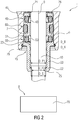
Figure 2 shows the high pressure pump with another example of the sealing unit which does not form part of the present invention; -
Figure 3 shows a sealing body of the sealing unit; and -
Figure 4 shows another embodiment of the sealing body. - The same elements, elements of the same type and elements having the same effect may be provided with the same reference signs in the figures.
-
Figure 1 and2 show a high pressure pump 1 with apump housing 5 and a later described sealingunit 15. The high pressure pump 1 is, for example, a high pressure pump 1 for the delivery of a fluid, for example, fuel or diesel in a vehicle. The high pressure pump 1 is, for example, designed to create pressures up to 200 bar for fuel and/or to create pressures up to 2500 bar and more for diesel. - The
pump housing 5 comprises ahousing cavity 7. Apiston 10 is arranged in thehousing cavity 7. Thepiston 10 is axially moveable within thehousing cavity 7 related to alongitudinal axis 9 of the high pressure pump 1. - The
piston 10 is coupled with adrive shaft 70, for example, with a camshaft on a driving side 8 of the high pressure pump 1. By the use of thedrive shaft 70 thepiston 10 can be moved in the axial direction. - The
piston 10 has a not shown axial end directed opposite to the driving side 8 of the high pressure pump 1. - The sealing
unit 15 is arranged radially outside of thepiston 10. The sealingunit 15 is arranged so that afirst part 21 of thehousing cavity 7 is sealed fluid-tight against asecond part 23 of thehousing cavity 7. - The sealing
unit 15 comprises a sealingbody 20 which is, for example, formed integrally.Figure 3 and 4 show two embodiments of the sealingbody 20. - The sealing
body 20 comprises aneck 22 with an inner diameter D_S. The inner diameter D_S is smaller than a first diameter D_P1 of a part of thepiston 10, which is arranged between theneck 22 of the sealingbody 20 and the axial end of thepiston 10. - The
piston 10 comprises a second diameter D_P2 in an axial area in which theneck 22 of the sealingbody 20 is arranged. The second diameter D_P2 of thepiston 10 is smaller than the first diameter D_P1 of thepiston 10. - For example, the sealing
body 20 axially protrudes over thehousing cavity 7 in direction to the driving side 8. - The sealing
body 20 comprises, for example, a firstaxial ending area 25 facing towards the driving side 8. - The
neck 22 of the sealingbody 20 is, for example, arranged in an area in which the sealingbody 20 protrudes over thehousing cavity 7 and/or, in particular, in the firstaxial ending area 25 of the sealingbody 20. - The sealing
body 20, for example, comprises aninner surface 24, which is facing towards thepiston 10. Theinner surface 24 comprises, for example, at least one sealing bulge 27 (Figure 3 ) protruding towards thepiston 10. - An inner diameter D_SB of the
respective sealing bulge 27 corresponds approximately to a respective diameter of thepiston 10 in an axial area of thepiston 10 in which therespective sealing bulge 27 is arranged, as, for example, to the first diameter D_P1 of thepiston 10. - The
respective sealing bulge 27 has for example a triangular shape. - The sealing
unit 15 comprises for example afirst seal 40 for sealing the fluid. Thefirst seal 40 comprises for example an o-ring 41 and alip 43 which is in contact with thepiston 10. - The sealing
unit 15 comprises for example asecond seal 50 for sealing another fluid as, for example, oil of thedrive shaft 70. Thesecond seal 50 comprises for example another o-ring 51 and anotherlip 53 which is in contact with thepiston 10. - The sealing
unit 15 comprises for example anouter seal 60 which is for example another o-ring which seals anouter surface 28 of the sealingbody 20 fluid-tight. Theouter surface 28 of the sealingbody 20 is facing towards thepump housing 5. - The sealing
body 20 comprises for example a second axial endingarea 26 directed opposite to the driving side 8 of the high pressure pump 1. For example, the second axial endingarea 26, radially overlaps thefirst seal 40. - For example, the
outer surface 28 of the sealingbody 20 comprises a retainingbulge 29. An outer diameter D_R of the retainingbulge 29 is, for example, larger than an inner diameter D_B of thepump housing 5 in an axial area of thepump housing 5 in which the retainingbulge 29 is arranged. - In the high pressure pump 1 shown in
figure 1 the retainingbulge 29 of the sealingbody 20 rests on a retainingring 31 of the high pressure pump 1, which is arranged in a designated recess of thepump housing 5. - In the high pressure pump 1 shown in
Figure 2 the sealingbody 20 is connected with thepump housing 5 by a press fit. - In the following the function of the high pressure pump 1 is described in brief:
- By a rotary movement of the driving
shaft 70 thepiston 10 is moved from an upper dead center to a lower dead center. Hereby fluid flows into a not shown high pressure chamber. By another rotary movement of the drivingshaft 70 thepiston 10 is moved in a stroke movement from the lower dead center to the upper dead center. By the stroke movement the fluid in the high pressure chamber is compressed. After the stroke movement the compressed fluid in the high pressure chamber can be released via an outlet valve. - Due to the high pressure a part of the compressed fluid can leak during the stroke movement from the high pressure chamber into the
first part 21 of thehousing cavity 7, where the second axial endingarea 26 of the sealingbody 20 is arranged. By the function of the sealingunit 15 this fluid does not get into contact with another fluid as, for example, with oil of the drivingshaft 70. - By the radially overlapping of the sealing
body 20 the fluid cannot come into direct contact with theseal 40 or at least not on a large surface of theseal 40. Thus the lifetime of theseal 40 can be increased because theseal 40 does not get damaged by the fluid. - By the function of the
neck 22 thepiston 10 is locked in thehousing cavity 7 during transport. - If the
neck 22 of the sealingbody 20 is arranged in the area in which the sealingbody 20 protrudes over thehousing cavity 7 and/or, in particular, in the firstaxial ending area 25 of the sealingbody 20, theneck 22 of the sealingbody 20 and/or the at least onesealing bulge 27 contribute to avoiding oil splashing on thepiston 10 on the driving side 8. - By the function of the retaining
bulge 29 of the sealingbody 20 an axial movement of the sealingbody 20 is prevented. -
- 1
- high pressure pump
- 5
- pump housing
- 7
- housing cavity
- 8
- driving side
- 9
- longitudinal axis
- 10
- piston
- 15
- sealing unit
- 20
- sealing body
- 21
- first part
- 22
- neck
- 23
- second part
- 24
- inner surface
- 25
- first axial ending area
- 26
- second axial ending area
- 27
- sealing bulge
- 28
- outer surface
- 29
- retaining bulge
- 31
- retaining ring
- 40
- first seal
- 41
- o-ring
- 43
- lip
- 50
- second seal
- 51
- o-ring
- 53
- lip
- 60
- outer seal
- 70
- driving shaft
- D_B
- inner diameter (of the pump housing)
- D_P1
- first diameter (of the piston)
- D_P2
- second diameter (of the piston)
- D_R
- outer diameter (of the retaining bulge)
- D_S
- inner diameter (of the neck)
- D_SB
- inner diameter (of the sealing bulge)
Claims (7)
- High pressure pump (1) for the delivery of a fluid comprising- a pump housing (5) with a longitudinal axis (9) and a housing cavity (7),- a piston (10) being partly arranged in the housing cavity (7) and being axially moveable within the housing cavity (7) and having an axial end directed opposite to a driving side (8) of the high pressure pump (1),- a sealing unit (15) with a sealing body (20) being arranged radially outside of the piston (10), so that a first part (21) of the housing cavity (7) is sealed fluid-tight against a second part (23) of the housing cavity (7), wherein the sealing body (20) comprises a neck (22) with an inner diameter (D_S) which is smaller than a first diameter (D_P1) of a part of the piston (10), which is arranged between the neck (22) of the sealing body (20) and the axial end of the piston (10), wherein the piston (10) comprises a second diameter (D_P2) in an axial area in which the neck (22) of the sealing body (20) is arranged, which is smaller than the first diameter (D_P1) of the piston (10),wherein the sealing body (20) comprises an outer surface (28), which is facing towards the pump housing (5), wherein the outer surface (28) of the sealing body (20) comprises a retaining bulge (29), wherein an outer diameter (D_R) of the retaining bulge (29) is larger than an inner diameter (D_B) of the pump housing (5) in an axial area of the pump housing (5) in which the retaining bulge (29) is arranged such that an axial movement of the sealing body (20) is prevented, characterized in that- a retaining ring (31), is arranged in a designates recess of the pump housing (5), wherein the retaining bulge (29) of the sealing body (20) rests on the retaining ring (31) such that an axial movement of the sealing body in direction to the driving side and in opposite direction is prevented.
- High pressure pump (1) according to claim 1, wherein the sealing body (20) axially protrudes over the housing cavity (7) in direction to the driving side (8) and the neck (22) of the sealing body (20) is arranged in an area in which the sealing body (20) protrudes over the housing cavity (7).
- High pressure pump (1) according to claim 1 or 2, wherein the sealing body (20) comprises a first axial ending area (25) facing towards the driving side (8), wherein the neck (22) of the sealing body (20) is arranged in the first axial ending area (25) of the sealing body (20).
- High pressure pump (1) according to one of the claims 1 to 3, wherein the sealing body (20) comprises an inner surface (24), which is facing towards the piston (10) and wherein the inner surface (24) comprises at least one sealing bulge (27) protruding towards the piston (10).
- High pressure pump (1) according to claim 4, wherein an inner diameter (D_SB) of the respective sealing bulge (27) corresponds approximately to a respective diameter of the piston (10) in an axial area of the piston (10) in which the respective sealing bulge (27) is arranged.
- High pressure pump (1) according to claim 4 or 5, wherein the respective sealing bulge (27) has a triangular shape.
- High pressure pump (1) according to one of the claims 1 to 6, wherein- the sealing unit (15) comprises a first seal (40) for sealing the fluid,- the sealing body (20) comprises a second axial ending area (26) direct opposite to the driving side (8) of the high pressure pump (1), wherein the second axial ending area (26) of the sealing body (20) radially overlaps the first seal (40).
Applications Claiming Priority (2)
| Application Number | Priority Date | Filing Date | Title |
|---|---|---|---|
| IN2629DE2013 | 2013-09-04 | ||
| PCT/EP2014/066558 WO2015032558A1 (en) | 2013-09-04 | 2014-07-31 | High pressure pump |
Publications (2)
| Publication Number | Publication Date |
|---|---|
| EP2941562A1 EP2941562A1 (en) | 2015-11-11 |
| EP2941562B1 true EP2941562B1 (en) | 2017-12-06 |
Family
ID=54250586
Family Applications (1)
| Application Number | Title | Priority Date | Filing Date |
|---|---|---|---|
| EP14747621.2A Not-in-force EP2941562B1 (en) | 2013-09-04 | 2014-07-31 | High pressure pump |
Country Status (6)
| Country | Link |
|---|---|
| US (1) | US10047743B2 (en) |
| EP (1) | EP2941562B1 (en) |
| JP (1) | JP6029776B2 (en) |
| KR (1) | KR101815796B1 (en) |
| CN (1) | CN105008718B (en) |
| WO (1) | WO2015032558A1 (en) |
Families Citing this family (9)
| Publication number | Priority date | Publication date | Assignee | Title |
|---|---|---|---|---|
| CN105927739B (en) * | 2016-05-25 | 2017-11-03 | 中国第一汽车股份有限公司无锡油泵油嘴研究所 | A kind of fuel oil Sealing used for pump |
| DE102016209930A1 (en) * | 2016-06-06 | 2017-12-07 | Elringklinger Ag | Piston device and pump device |
| DE102016120967A1 (en) * | 2016-11-03 | 2018-05-03 | Avl List Gmbh | Length adjustable connecting rod with a cylinder-piston unit with multiple piston seals |
| CN106762299B (en) * | 2017-01-23 | 2023-06-20 | 联合汽车电子有限公司 | High-pressure pump |
| US10801493B2 (en) * | 2017-12-14 | 2020-10-13 | William E. Howseman, Jr. | Positive displacement reciprocating pump assembly for dispensing predeterminedly precise amounts of fluid during both the up and down strokes of the pump piston |
| EP3514380A1 (en) | 2018-01-23 | 2019-07-24 | Maximator Gmbh | Compressor and method for compressing a working medium |
| KR102263660B1 (en) * | 2019-12-17 | 2021-06-10 | 주식회사 현대케피코 | Guide for piston of High pressure pump |
| DE102020208202A1 (en) * | 2020-07-01 | 2022-01-05 | Robert Bosch Gesellschaft mit beschränkter Haftung | High pressure fuel pump |
| CN112377404B (en) * | 2020-11-20 | 2021-12-17 | 江苏核电有限公司 | Nuclear-grade plunger pump sealing assembly and installation and adjustment method thereof |
Citations (1)
| Publication number | Priority date | Publication date | Assignee | Title |
|---|---|---|---|---|
| DE102004047601A1 (en) * | 2004-08-13 | 2006-02-23 | Robert Bosch Gmbh | Fluid pump e.g. high-pressure fluid pump, for internal combustion engine, has extension in flow path leading from inlet to chamber and multifunction unit arranged in extension and including retaining section for retaining filter device |
Family Cites Families (10)
| Publication number | Priority date | Publication date | Assignee | Title |
|---|---|---|---|---|
| US4976192A (en) * | 1989-01-09 | 1990-12-11 | Mcneil (Ohio) Corporation | Reciprocating pump |
| US4906167A (en) * | 1989-02-07 | 1990-03-06 | Dresser Industries, Inc. | Inherently flushing piston rod for a reciprocating pump |
| JP4066899B2 (en) * | 2003-06-30 | 2008-03-26 | Nok株式会社 | Sealing device |
| US7637508B2 (en) * | 2004-03-19 | 2009-12-29 | Interpump Engineering S.R.L. | High temperature high pressure seal stack having run-dry capability |
| JP2007009750A (en) | 2005-06-29 | 2007-01-18 | Toyota Motor Corp | Fuel pump seal structure and fuel pump having the seal structure |
| JP4386030B2 (en) | 2005-12-02 | 2009-12-16 | トヨタ自動車株式会社 | High pressure pump |
| JP4414966B2 (en) * | 2006-01-16 | 2010-02-17 | Nok株式会社 | High pressure fuel pump and sealing system for high pressure fuel pump |
| DE102006055298A1 (en) * | 2006-11-23 | 2008-06-05 | Elringklinger Ag | sealing arrangement |
| JP5195893B2 (en) | 2010-12-24 | 2013-05-15 | トヨタ自動車株式会社 | High pressure pump |
| JP5209746B2 (en) * | 2011-01-27 | 2013-06-12 | 株式会社デンソー | High pressure pump |
-
2014
- 2014-07-31 CN CN201480011237.8A patent/CN105008718B/en active Active
- 2014-07-31 US US14/762,567 patent/US10047743B2/en active Active
- 2014-07-31 WO PCT/EP2014/066558 patent/WO2015032558A1/en not_active Ceased
- 2014-07-31 KR KR1020167006727A patent/KR101815796B1/en not_active Expired - Fee Related
- 2014-07-31 JP JP2015559525A patent/JP6029776B2/en not_active Expired - Fee Related
- 2014-07-31 EP EP14747621.2A patent/EP2941562B1/en not_active Not-in-force
Patent Citations (1)
| Publication number | Priority date | Publication date | Assignee | Title |
|---|---|---|---|---|
| DE102004047601A1 (en) * | 2004-08-13 | 2006-02-23 | Robert Bosch Gmbh | Fluid pump e.g. high-pressure fluid pump, for internal combustion engine, has extension in flow path leading from inlet to chamber and multifunction unit arranged in extension and including retaining section for retaining filter device |
Also Published As
| Publication number | Publication date |
|---|---|
| US10047743B2 (en) | 2018-08-14 |
| US20160186742A1 (en) | 2016-06-30 |
| JP6029776B2 (en) | 2016-11-24 |
| CN105008718A (en) | 2015-10-28 |
| WO2015032558A1 (en) | 2015-03-12 |
| KR20160042454A (en) | 2016-04-19 |
| KR101815796B1 (en) | 2018-01-05 |
| JP2016508577A (en) | 2016-03-22 |
| EP2941562A1 (en) | 2015-11-11 |
| CN105008718B (en) | 2017-03-08 |
Similar Documents
| Publication | Publication Date | Title |
|---|---|---|
| US10047743B2 (en) | High pressure pump | |
| US7665976B2 (en) | High pressure fuel pump for internal combustion engine | |
| CN104854341B (en) | Piston type fuel pump for internal combustion engine | |
| EP2129869B1 (en) | Low leakage plunger assembly for a high pressure fluid system | |
| US20150017035A1 (en) | Pump head for a fuel pump | |
| CN111480000B (en) | Fuel supply pump | |
| JP2018506677A (en) | Plunger assembly | |
| US20170037879A1 (en) | Hydraulic actuator for cryogenic pump | |
| JP2020020342A (en) | High-pressure fuel pump and its manufacturing method | |
| JP6849892B2 (en) | Piston pump device | |
| CN106460758A (en) | Piston fuel pump for an internal combustion engine | |
| KR20200033254A (en) | Piston pumps, especially high pressure fuel pumps for internal combustion engines | |
| US9951733B2 (en) | Plug-in pump | |
| US20090229571A1 (en) | Pressure booster arrangement | |
| CN107636291A (en) | Fuel pump components | |
| JP2017529485A (en) | High pressure fuel pump for internal combustion engines, especially for fuel injection devices | |
| CN109209852B (en) | Rod seal for piston pump | |
| JP2008057527A (en) | Plunger pump | |
| JP5326384B2 (en) | Sealing device | |
| US8123505B2 (en) | Reciprocating pump with sealing collar arrangement | |
| JP4730373B2 (en) | Fuel injection valve | |
| JP6849891B2 (en) | Piston pump rod packing | |
| WO2015032533A1 (en) | High pressure pump | |
| US20060214021A1 (en) | Hydraulic coupler and fuel injection valve | |
| JP2018178969A (en) | High pressure fuel supply pump |
Legal Events
| Date | Code | Title | Description |
|---|---|---|---|
| PUAI | Public reference made under article 153(3) epc to a published international application that has entered the european phase |
Free format text: ORIGINAL CODE: 0009012 |
|
| 17P | Request for examination filed |
Effective date: 20150715 |
|
| AK | Designated contracting states |
Kind code of ref document: A1 Designated state(s): AL AT BE BG CH CY CZ DE DK EE ES FI FR GB GR HR HU IE IS IT LI LT LU LV MC MK MT NL NO PL PT RO RS SE SI SK SM TR |
|
| AX | Request for extension of the european patent |
Extension state: BA ME |
|
| 17Q | First examination report despatched |
Effective date: 20161014 |
|
| DAX | Request for extension of the european patent (deleted) | ||
| REG | Reference to a national code |
Ref country code: DE Ref legal event code: R079 Ref document number: 602014018207 Country of ref document: DE Free format text: PREVIOUS MAIN CLASS: F04B0001040000 Ipc: F04B0053000000 |
|
| GRAP | Despatch of communication of intention to grant a patent |
Free format text: ORIGINAL CODE: EPIDOSNIGR1 |
|
| RIC1 | Information provided on ipc code assigned before grant |
Ipc: F04B 53/02 20060101ALI20170608BHEP Ipc: F04B 53/00 20060101AFI20170608BHEP Ipc: F02M 59/44 20060101ALI20170608BHEP Ipc: F04B 53/22 20060101ALI20170608BHEP |
|
| INTG | Intention to grant announced |
Effective date: 20170629 |
|
| GRAS | Grant fee paid |
Free format text: ORIGINAL CODE: EPIDOSNIGR3 |
|
| GRAA | (expected) grant |
Free format text: ORIGINAL CODE: 0009210 |
|
| AK | Designated contracting states |
Kind code of ref document: B1 Designated state(s): AL AT BE BG CH CY CZ DE DK EE ES FI FR GB GR HR HU IE IS IT LI LT LU LV MC MK MT NL NO PL PT RO RS SE SI SK SM TR |
|
| REG | Reference to a national code |
Ref country code: GB Ref legal event code: FG4D |
|
| REG | Reference to a national code |
Ref country code: AT Ref legal event code: REF Ref document number: 952634 Country of ref document: AT Kind code of ref document: T Effective date: 20171215 Ref country code: CH Ref legal event code: EP |
|
| REG | Reference to a national code |
Ref country code: IE Ref legal event code: FG4D |
|
| REG | Reference to a national code |
Ref country code: DE Ref legal event code: R096 Ref document number: 602014018207 Country of ref document: DE |
|
| REG | Reference to a national code |
Ref country code: NL Ref legal event code: MP Effective date: 20171206 |
|
| REG | Reference to a national code |
Ref country code: LT Ref legal event code: MG4D |
|
| PG25 | Lapsed in a contracting state [announced via postgrant information from national office to epo] |
Ref country code: FI Free format text: LAPSE BECAUSE OF FAILURE TO SUBMIT A TRANSLATION OF THE DESCRIPTION OR TO PAY THE FEE WITHIN THE PRESCRIBED TIME-LIMIT Effective date: 20171206 Ref country code: NO Free format text: LAPSE BECAUSE OF FAILURE TO SUBMIT A TRANSLATION OF THE DESCRIPTION OR TO PAY THE FEE WITHIN THE PRESCRIBED TIME-LIMIT Effective date: 20180306 Ref country code: SE Free format text: LAPSE BECAUSE OF FAILURE TO SUBMIT A TRANSLATION OF THE DESCRIPTION OR TO PAY THE FEE WITHIN THE PRESCRIBED TIME-LIMIT Effective date: 20171206 Ref country code: ES Free format text: LAPSE BECAUSE OF FAILURE TO SUBMIT A TRANSLATION OF THE DESCRIPTION OR TO PAY THE FEE WITHIN THE PRESCRIBED TIME-LIMIT Effective date: 20171206 Ref country code: LT Free format text: LAPSE BECAUSE OF FAILURE TO SUBMIT A TRANSLATION OF THE DESCRIPTION OR TO PAY THE FEE WITHIN THE PRESCRIBED TIME-LIMIT Effective date: 20171206 |
|
| REG | Reference to a national code |
Ref country code: AT Ref legal event code: MK05 Ref document number: 952634 Country of ref document: AT Kind code of ref document: T Effective date: 20171206 |
|
| PG25 | Lapsed in a contracting state [announced via postgrant information from national office to epo] |
Ref country code: HR Free format text: LAPSE BECAUSE OF FAILURE TO SUBMIT A TRANSLATION OF THE DESCRIPTION OR TO PAY THE FEE WITHIN THE PRESCRIBED TIME-LIMIT Effective date: 20171206 Ref country code: RS Free format text: LAPSE BECAUSE OF FAILURE TO SUBMIT A TRANSLATION OF THE DESCRIPTION OR TO PAY THE FEE WITHIN THE PRESCRIBED TIME-LIMIT Effective date: 20171206 Ref country code: GR Free format text: LAPSE BECAUSE OF FAILURE TO SUBMIT A TRANSLATION OF THE DESCRIPTION OR TO PAY THE FEE WITHIN THE PRESCRIBED TIME-LIMIT Effective date: 20180307 Ref country code: LV Free format text: LAPSE BECAUSE OF FAILURE TO SUBMIT A TRANSLATION OF THE DESCRIPTION OR TO PAY THE FEE WITHIN THE PRESCRIBED TIME-LIMIT Effective date: 20171206 Ref country code: BG Free format text: LAPSE BECAUSE OF FAILURE TO SUBMIT A TRANSLATION OF THE DESCRIPTION OR TO PAY THE FEE WITHIN THE PRESCRIBED TIME-LIMIT Effective date: 20180306 |
|
| PG25 | Lapsed in a contracting state [announced via postgrant information from national office to epo] |
Ref country code: NL Free format text: LAPSE BECAUSE OF FAILURE TO SUBMIT A TRANSLATION OF THE DESCRIPTION OR TO PAY THE FEE WITHIN THE PRESCRIBED TIME-LIMIT Effective date: 20171206 |
|
| REG | Reference to a national code |
Ref country code: FR Ref legal event code: PLFP Year of fee payment: 5 |
|
| PG25 | Lapsed in a contracting state [announced via postgrant information from national office to epo] |
Ref country code: CZ Free format text: LAPSE BECAUSE OF FAILURE TO SUBMIT A TRANSLATION OF THE DESCRIPTION OR TO PAY THE FEE WITHIN THE PRESCRIBED TIME-LIMIT Effective date: 20171206 Ref country code: SK Free format text: LAPSE BECAUSE OF FAILURE TO SUBMIT A TRANSLATION OF THE DESCRIPTION OR TO PAY THE FEE WITHIN THE PRESCRIBED TIME-LIMIT Effective date: 20171206 Ref country code: EE Free format text: LAPSE BECAUSE OF FAILURE TO SUBMIT A TRANSLATION OF THE DESCRIPTION OR TO PAY THE FEE WITHIN THE PRESCRIBED TIME-LIMIT Effective date: 20171206 |
|
| PG25 | Lapsed in a contracting state [announced via postgrant information from national office to epo] |
Ref country code: PL Free format text: LAPSE BECAUSE OF FAILURE TO SUBMIT A TRANSLATION OF THE DESCRIPTION OR TO PAY THE FEE WITHIN THE PRESCRIBED TIME-LIMIT Effective date: 20171206 Ref country code: RO Free format text: LAPSE BECAUSE OF FAILURE TO SUBMIT A TRANSLATION OF THE DESCRIPTION OR TO PAY THE FEE WITHIN THE PRESCRIBED TIME-LIMIT Effective date: 20171206 Ref country code: SM Free format text: LAPSE BECAUSE OF FAILURE TO SUBMIT A TRANSLATION OF THE DESCRIPTION OR TO PAY THE FEE WITHIN THE PRESCRIBED TIME-LIMIT Effective date: 20171206 Ref country code: AT Free format text: LAPSE BECAUSE OF FAILURE TO SUBMIT A TRANSLATION OF THE DESCRIPTION OR TO PAY THE FEE WITHIN THE PRESCRIBED TIME-LIMIT Effective date: 20171206 Ref country code: IT Free format text: LAPSE BECAUSE OF FAILURE TO SUBMIT A TRANSLATION OF THE DESCRIPTION OR TO PAY THE FEE WITHIN THE PRESCRIBED TIME-LIMIT Effective date: 20171206 |
|
| REG | Reference to a national code |
Ref country code: DE Ref legal event code: R097 Ref document number: 602014018207 Country of ref document: DE |
|
| PLBE | No opposition filed within time limit |
Free format text: ORIGINAL CODE: 0009261 |
|
| STAA | Information on the status of an ep patent application or granted ep patent |
Free format text: STATUS: NO OPPOSITION FILED WITHIN TIME LIMIT |
|
| 26N | No opposition filed |
Effective date: 20180907 |
|
| PG25 | Lapsed in a contracting state [announced via postgrant information from national office to epo] |
Ref country code: DK Free format text: LAPSE BECAUSE OF FAILURE TO SUBMIT A TRANSLATION OF THE DESCRIPTION OR TO PAY THE FEE WITHIN THE PRESCRIBED TIME-LIMIT Effective date: 20171206 Ref country code: SI Free format text: LAPSE BECAUSE OF FAILURE TO SUBMIT A TRANSLATION OF THE DESCRIPTION OR TO PAY THE FEE WITHIN THE PRESCRIBED TIME-LIMIT Effective date: 20171206 |
|
| REG | Reference to a national code |
Ref country code: CH Ref legal event code: PL |
|
| PG25 | Lapsed in a contracting state [announced via postgrant information from national office to epo] |
Ref country code: LU Free format text: LAPSE BECAUSE OF NON-PAYMENT OF DUE FEES Effective date: 20180731 Ref country code: MC Free format text: LAPSE BECAUSE OF FAILURE TO SUBMIT A TRANSLATION OF THE DESCRIPTION OR TO PAY THE FEE WITHIN THE PRESCRIBED TIME-LIMIT Effective date: 20171206 |
|
| REG | Reference to a national code |
Ref country code: BE Ref legal event code: MM Effective date: 20180731 |
|
| PG25 | Lapsed in a contracting state [announced via postgrant information from national office to epo] |
Ref country code: LI Free format text: LAPSE BECAUSE OF NON-PAYMENT OF DUE FEES Effective date: 20180731 Ref country code: CH Free format text: LAPSE BECAUSE OF NON-PAYMENT OF DUE FEES Effective date: 20180731 |
|
| REG | Reference to a national code |
Ref country code: IE Ref legal event code: MM4A |
|
| PG25 | Lapsed in a contracting state [announced via postgrant information from national office to epo] |
Ref country code: BE Free format text: LAPSE BECAUSE OF NON-PAYMENT OF DUE FEES Effective date: 20180731 |
|
| PG25 | Lapsed in a contracting state [announced via postgrant information from national office to epo] |
Ref country code: IE Free format text: LAPSE BECAUSE OF NON-PAYMENT OF DUE FEES Effective date: 20180731 |
|
| PG25 | Lapsed in a contracting state [announced via postgrant information from national office to epo] |
Ref country code: MT Free format text: LAPSE BECAUSE OF NON-PAYMENT OF DUE FEES Effective date: 20180731 |
|
| PG25 | Lapsed in a contracting state [announced via postgrant information from national office to epo] |
Ref country code: TR Free format text: LAPSE BECAUSE OF FAILURE TO SUBMIT A TRANSLATION OF THE DESCRIPTION OR TO PAY THE FEE WITHIN THE PRESCRIBED TIME-LIMIT Effective date: 20171206 |
|
| PG25 | Lapsed in a contracting state [announced via postgrant information from national office to epo] |
Ref country code: PT Free format text: LAPSE BECAUSE OF FAILURE TO SUBMIT A TRANSLATION OF THE DESCRIPTION OR TO PAY THE FEE WITHIN THE PRESCRIBED TIME-LIMIT Effective date: 20171206 |
|
| REG | Reference to a national code |
Ref country code: DE Ref legal event code: R081 Ref document number: 602014018207 Country of ref document: DE Owner name: VITESCO TECHNOLOGIES GMBH, DE Free format text: FORMER OWNER: CONTINENTAL AUTOMOTIVE GMBH, 30165 HANNOVER, DE |
|
| PG25 | Lapsed in a contracting state [announced via postgrant information from national office to epo] |
Ref country code: HU Free format text: LAPSE BECAUSE OF FAILURE TO SUBMIT A TRANSLATION OF THE DESCRIPTION OR TO PAY THE FEE WITHIN THE PRESCRIBED TIME-LIMIT; INVALID AB INITIO Effective date: 20140731 Ref country code: CY Free format text: LAPSE BECAUSE OF FAILURE TO SUBMIT A TRANSLATION OF THE DESCRIPTION OR TO PAY THE FEE WITHIN THE PRESCRIBED TIME-LIMIT Effective date: 20171206 Ref country code: MK Free format text: LAPSE BECAUSE OF NON-PAYMENT OF DUE FEES Effective date: 20171206 |
|
| PG25 | Lapsed in a contracting state [announced via postgrant information from national office to epo] |
Ref country code: AL Free format text: LAPSE BECAUSE OF FAILURE TO SUBMIT A TRANSLATION OF THE DESCRIPTION OR TO PAY THE FEE WITHIN THE PRESCRIBED TIME-LIMIT Effective date: 20171206 Ref country code: IS Free format text: LAPSE BECAUSE OF FAILURE TO SUBMIT A TRANSLATION OF THE DESCRIPTION OR TO PAY THE FEE WITHIN THE PRESCRIBED TIME-LIMIT Effective date: 20180406 |
|
| REG | Reference to a national code |
Ref country code: DE Ref legal event code: R081 Ref document number: 602014018207 Country of ref document: DE Owner name: VITESCO TECHNOLOGIES GMBH, DE Free format text: FORMER OWNER: VITESCO TECHNOLOGIES GMBH, 30165 HANNOVER, DE |
|
| REG | Reference to a national code |
Ref country code: GB Ref legal event code: 732E Free format text: REGISTERED BETWEEN 20230427 AND 20230503 |
|
| P01 | Opt-out of the competence of the unified patent court (upc) registered |
Effective date: 20230530 |
|
| PGFP | Annual fee paid to national office [announced via postgrant information from national office to epo] |
Ref country code: DE Payment date: 20240731 Year of fee payment: 11 |
|
| PGFP | Annual fee paid to national office [announced via postgrant information from national office to epo] |
Ref country code: GB Payment date: 20240725 Year of fee payment: 11 |
|
| PGFP | Annual fee paid to national office [announced via postgrant information from national office to epo] |
Ref country code: FR Payment date: 20240730 Year of fee payment: 11 |
|
| REG | Reference to a national code |
Ref country code: DE Ref legal event code: R119 Ref document number: 602014018207 Country of ref document: DE |
|
| GBPC | Gb: european patent ceased through non-payment of renewal fee |
Effective date: 20250731 |
|
| PG25 | Lapsed in a contracting state [announced via postgrant information from national office to epo] |
Ref country code: GB Free format text: LAPSE BECAUSE OF NON-PAYMENT OF DUE FEES Effective date: 20250731 |
|
| PG25 | Lapsed in a contracting state [announced via postgrant information from national office to epo] |
Ref country code: DE Free format text: LAPSE BECAUSE OF NON-PAYMENT OF DUE FEES Effective date: 20260203 |
|
| PG25 | Lapsed in a contracting state [announced via postgrant information from national office to epo] |
Ref country code: FR Free format text: LAPSE BECAUSE OF NON-PAYMENT OF DUE FEES Effective date: 20250731 |