EP2941343B1 - Induction heating compaction system and method of compacting - Google Patents
Induction heating compaction system and method of compacting Download PDFInfo
- Publication number
- EP2941343B1 EP2941343B1 EP14701134.0A EP14701134A EP2941343B1 EP 2941343 B1 EP2941343 B1 EP 2941343B1 EP 14701134 A EP14701134 A EP 14701134A EP 2941343 B1 EP2941343 B1 EP 2941343B1
- Authority
- EP
- European Patent Office
- Prior art keywords
- compaction
- preg material
- roller
- induction heating
- ply layer
- Prior art date
- Legal status (The legal status is an assumption and is not a legal conclusion. Google has not performed a legal analysis and makes no representation as to the accuracy of the status listed.)
- Active
Links
Images



Classifications
-
- B—PERFORMING OPERATIONS; TRANSPORTING
- B29—WORKING OF PLASTICS; WORKING OF SUBSTANCES IN A PLASTIC STATE IN GENERAL
- B29C—SHAPING OR JOINING OF PLASTICS; SHAPING OF MATERIAL IN A PLASTIC STATE, NOT OTHERWISE PROVIDED FOR; AFTER-TREATMENT OF THE SHAPED PRODUCTS, e.g. REPAIRING
- B29C70/00—Shaping composites, i.e. plastics material comprising reinforcements, fillers or preformed parts, e.g. inserts
- B29C70/04—Shaping composites, i.e. plastics material comprising reinforcements, fillers or preformed parts, e.g. inserts comprising reinforcements only, e.g. self-reinforcing plastics
- B29C70/28—Shaping operations therefor
- B29C70/30—Shaping by lay-up, i.e. applying fibres, tape or broadsheet on a mould, former or core; Shaping by spray-up, i.e. spraying of fibres on a mould, former or core
- B29C70/38—Automated lay-up, e.g. using robots, laying filaments according to predetermined patterns
-
- B—PERFORMING OPERATIONS; TRANSPORTING
- B29—WORKING OF PLASTICS; WORKING OF SUBSTANCES IN A PLASTIC STATE IN GENERAL
- B29C—SHAPING OR JOINING OF PLASTICS; SHAPING OF MATERIAL IN A PLASTIC STATE, NOT OTHERWISE PROVIDED FOR; AFTER-TREATMENT OF THE SHAPED PRODUCTS, e.g. REPAIRING
- B29C70/00—Shaping composites, i.e. plastics material comprising reinforcements, fillers or preformed parts, e.g. inserts
- B29C70/04—Shaping composites, i.e. plastics material comprising reinforcements, fillers or preformed parts, e.g. inserts comprising reinforcements only, e.g. self-reinforcing plastics
- B29C70/28—Shaping operations therefor
- B29C70/30—Shaping by lay-up, i.e. applying fibres, tape or broadsheet on a mould, former or core; Shaping by spray-up, i.e. spraying of fibres on a mould, former or core
- B29C70/38—Automated lay-up, e.g. using robots, laying filaments according to predetermined patterns
- B29C70/386—Automated tape laying [ATL]
- B29C70/388—Tape placement heads, e.g. component parts, details or accessories
-
- B—PERFORMING OPERATIONS; TRANSPORTING
- B29—WORKING OF PLASTICS; WORKING OF SUBSTANCES IN A PLASTIC STATE IN GENERAL
- B29C—SHAPING OR JOINING OF PLASTICS; SHAPING OF MATERIAL IN A PLASTIC STATE, NOT OTHERWISE PROVIDED FOR; AFTER-TREATMENT OF THE SHAPED PRODUCTS, e.g. REPAIRING
- B29C70/00—Shaping composites, i.e. plastics material comprising reinforcements, fillers or preformed parts, e.g. inserts
- B29C70/04—Shaping composites, i.e. plastics material comprising reinforcements, fillers or preformed parts, e.g. inserts comprising reinforcements only, e.g. self-reinforcing plastics
- B29C70/28—Shaping operations therefor
- B29C70/30—Shaping by lay-up, i.e. applying fibres, tape or broadsheet on a mould, former or core; Shaping by spray-up, i.e. spraying of fibres on a mould, former or core
- B29C70/38—Automated lay-up, e.g. using robots, laying filaments according to predetermined patterns
- B29C70/386—Automated tape laying [ATL]
-
- B—PERFORMING OPERATIONS; TRANSPORTING
- B29—WORKING OF PLASTICS; WORKING OF SUBSTANCES IN A PLASTIC STATE IN GENERAL
- B29C—SHAPING OR JOINING OF PLASTICS; SHAPING OF MATERIAL IN A PLASTIC STATE, NOT OTHERWISE PROVIDED FOR; AFTER-TREATMENT OF THE SHAPED PRODUCTS, e.g. REPAIRING
- B29C35/00—Heating, cooling or curing, e.g. crosslinking or vulcanising; Apparatus therefor
- B29C35/02—Heating or curing, e.g. crosslinking or vulcanizing during moulding, e.g. in a mould
- B29C35/08—Heating or curing, e.g. crosslinking or vulcanizing during moulding, e.g. in a mould by wave energy or particle radiation
- B29C35/0805—Heating or curing, e.g. crosslinking or vulcanizing during moulding, e.g. in a mould by wave energy or particle radiation using electromagnetic radiation
-
- B—PERFORMING OPERATIONS; TRANSPORTING
- B29—WORKING OF PLASTICS; WORKING OF SUBSTANCES IN A PLASTIC STATE IN GENERAL
- B29C—SHAPING OR JOINING OF PLASTICS; SHAPING OF MATERIAL IN A PLASTIC STATE, NOT OTHERWISE PROVIDED FOR; AFTER-TREATMENT OF THE SHAPED PRODUCTS, e.g. REPAIRING
- B29C35/00—Heating, cooling or curing, e.g. crosslinking or vulcanising; Apparatus therefor
- B29C35/16—Cooling
-
- B—PERFORMING OPERATIONS; TRANSPORTING
- B29—WORKING OF PLASTICS; WORKING OF SUBSTANCES IN A PLASTIC STATE IN GENERAL
- B29C—SHAPING OR JOINING OF PLASTICS; SHAPING OF MATERIAL IN A PLASTIC STATE, NOT OTHERWISE PROVIDED FOR; AFTER-TREATMENT OF THE SHAPED PRODUCTS, e.g. REPAIRING
- B29C65/00—Joining or sealing of preformed parts, e.g. welding of plastics materials; Apparatus therefor
- B29C65/02—Joining or sealing of preformed parts, e.g. welding of plastics materials; Apparatus therefor by heating, with or without pressure
- B29C65/14—Joining or sealing of preformed parts, e.g. welding of plastics materials; Apparatus therefor by heating, with or without pressure using wave energy, i.e. electromagnetic radiation, or particle radiation
- B29C65/1403—Joining or sealing of preformed parts, e.g. welding of plastics materials; Apparatus therefor by heating, with or without pressure using wave energy, i.e. electromagnetic radiation, or particle radiation characterised by the type of electromagnetic or particle radiation
-
- B—PERFORMING OPERATIONS; TRANSPORTING
- B29—WORKING OF PLASTICS; WORKING OF SUBSTANCES IN A PLASTIC STATE IN GENERAL
- B29C—SHAPING OR JOINING OF PLASTICS; SHAPING OF MATERIAL IN A PLASTIC STATE, NOT OTHERWISE PROVIDED FOR; AFTER-TREATMENT OF THE SHAPED PRODUCTS, e.g. REPAIRING
- B29C65/00—Joining or sealing of preformed parts, e.g. welding of plastics materials; Apparatus therefor
- B29C65/02—Joining or sealing of preformed parts, e.g. welding of plastics materials; Apparatus therefor by heating, with or without pressure
- B29C65/34—Joining or sealing of preformed parts, e.g. welding of plastics materials; Apparatus therefor by heating, with or without pressure using heated elements which remain in the joint, e.g. "verlorenes Schweisselement"
-
- B—PERFORMING OPERATIONS; TRANSPORTING
- B29—WORKING OF PLASTICS; WORKING OF SUBSTANCES IN A PLASTIC STATE IN GENERAL
- B29C—SHAPING OR JOINING OF PLASTICS; SHAPING OF MATERIAL IN A PLASTIC STATE, NOT OTHERWISE PROVIDED FOR; AFTER-TREATMENT OF THE SHAPED PRODUCTS, e.g. REPAIRING
- B29C65/00—Joining or sealing of preformed parts, e.g. welding of plastics materials; Apparatus therefor
- B29C65/02—Joining or sealing of preformed parts, e.g. welding of plastics materials; Apparatus therefor by heating, with or without pressure
- B29C65/34—Joining or sealing of preformed parts, e.g. welding of plastics materials; Apparatus therefor by heating, with or without pressure using heated elements which remain in the joint, e.g. "verlorenes Schweisselement"
- B29C65/36—Joining or sealing of preformed parts, e.g. welding of plastics materials; Apparatus therefor by heating, with or without pressure using heated elements which remain in the joint, e.g. "verlorenes Schweisselement" heated by induction
-
- B—PERFORMING OPERATIONS; TRANSPORTING
- B29—WORKING OF PLASTICS; WORKING OF SUBSTANCES IN A PLASTIC STATE IN GENERAL
- B29C—SHAPING OR JOINING OF PLASTICS; SHAPING OF MATERIAL IN A PLASTIC STATE, NOT OTHERWISE PROVIDED FOR; AFTER-TREATMENT OF THE SHAPED PRODUCTS, e.g. REPAIRING
- B29C66/00—General aspects of processes or apparatus for joining preformed parts
- B29C66/01—General aspects dealing with the joint area or with the area to be joined
- B29C66/05—Particular design of joint configurations
- B29C66/10—Particular design of joint configurations particular design of the joint cross-sections
- B29C66/11—Joint cross-sections comprising a single joint-segment, i.e. one of the parts to be joined comprising a single joint-segment in the joint cross-section
- B29C66/112—Single lapped joints
- B29C66/1122—Single lap to lap joints, i.e. overlap joints
-
- B—PERFORMING OPERATIONS; TRANSPORTING
- B29—WORKING OF PLASTICS; WORKING OF SUBSTANCES IN A PLASTIC STATE IN GENERAL
- B29C—SHAPING OR JOINING OF PLASTICS; SHAPING OF MATERIAL IN A PLASTIC STATE, NOT OTHERWISE PROVIDED FOR; AFTER-TREATMENT OF THE SHAPED PRODUCTS, e.g. REPAIRING
- B29C66/00—General aspects of processes or apparatus for joining preformed parts
- B29C66/01—General aspects dealing with the joint area or with the area to be joined
- B29C66/349—Cooling the welding zone on the welding spot
-
- B—PERFORMING OPERATIONS; TRANSPORTING
- B29—WORKING OF PLASTICS; WORKING OF SUBSTANCES IN A PLASTIC STATE IN GENERAL
- B29C—SHAPING OR JOINING OF PLASTICS; SHAPING OF MATERIAL IN A PLASTIC STATE, NOT OTHERWISE PROVIDED FOR; AFTER-TREATMENT OF THE SHAPED PRODUCTS, e.g. REPAIRING
- B29C66/00—General aspects of processes or apparatus for joining preformed parts
- B29C66/40—General aspects of joining substantially flat articles, e.g. plates, sheets or web-like materials; Making flat seams in tubular or hollow articles; Joining single elements to substantially flat surfaces
- B29C66/41—Joining substantially flat articles ; Making flat seams in tubular or hollow articles
- B29C66/45—Joining of substantially the whole surface of the articles
-
- B—PERFORMING OPERATIONS; TRANSPORTING
- B29—WORKING OF PLASTICS; WORKING OF SUBSTANCES IN A PLASTIC STATE IN GENERAL
- B29C—SHAPING OR JOINING OF PLASTICS; SHAPING OF MATERIAL IN A PLASTIC STATE, NOT OTHERWISE PROVIDED FOR; AFTER-TREATMENT OF THE SHAPED PRODUCTS, e.g. REPAIRING
- B29C66/00—General aspects of processes or apparatus for joining preformed parts
- B29C66/70—General aspects of processes or apparatus for joining preformed parts characterised by the composition, physical properties or the structure of the material of the parts to be joined; Joining with non-plastics material
- B29C66/72—General aspects of processes or apparatus for joining preformed parts characterised by the composition, physical properties or the structure of the material of the parts to be joined; Joining with non-plastics material characterised by the structure of the material of the parts to be joined
- B29C66/721—Fibre-reinforced materials
-
- B—PERFORMING OPERATIONS; TRANSPORTING
- B29—WORKING OF PLASTICS; WORKING OF SUBSTANCES IN A PLASTIC STATE IN GENERAL
- B29C—SHAPING OR JOINING OF PLASTICS; SHAPING OF MATERIAL IN A PLASTIC STATE, NOT OTHERWISE PROVIDED FOR; AFTER-TREATMENT OF THE SHAPED PRODUCTS, e.g. REPAIRING
- B29C66/00—General aspects of processes or apparatus for joining preformed parts
- B29C66/80—General aspects of machine operations or constructions and parts thereof
- B29C66/81—General aspects of the pressing elements, i.e. the elements applying pressure on the parts to be joined in the area to be joined, e.g. the welding jaws or clamps
- B29C66/818—General aspects of the pressing elements, i.e. the elements applying pressure on the parts to be joined in the area to be joined, e.g. the welding jaws or clamps characterised by the cooling constructional aspects, or by the thermal or electrical insulating or conducting constructional aspects of the welding jaws or of the clamps ; comprising means for compensating for the thermal expansion of the welding jaws or of the clamps
- B29C66/8181—General aspects of the pressing elements, i.e. the elements applying pressure on the parts to be joined in the area to be joined, e.g. the welding jaws or clamps characterised by the cooling constructional aspects, or by the thermal or electrical insulating or conducting constructional aspects of the welding jaws or of the clamps ; comprising means for compensating for the thermal expansion of the welding jaws or of the clamps characterised by the cooling constructional aspects
-
- B—PERFORMING OPERATIONS; TRANSPORTING
- B29—WORKING OF PLASTICS; WORKING OF SUBSTANCES IN A PLASTIC STATE IN GENERAL
- B29C—SHAPING OR JOINING OF PLASTICS; SHAPING OF MATERIAL IN A PLASTIC STATE, NOT OTHERWISE PROVIDED FOR; AFTER-TREATMENT OF THE SHAPED PRODUCTS, e.g. REPAIRING
- B29C66/00—General aspects of processes or apparatus for joining preformed parts
- B29C66/80—General aspects of machine operations or constructions and parts thereof
- B29C66/83—General aspects of machine operations or constructions and parts thereof characterised by the movement of the joining or pressing tools
- B29C66/836—Moving relative to and tangentially to the parts to be joined, e.g. transversely to the displacement of the parts to be joined, e.g. using a X-Y table
- B29C66/8362—Rollers, cylinders or drums moving relative to and tangentially to the parts to be joined
-
- B—PERFORMING OPERATIONS; TRANSPORTING
- B29—WORKING OF PLASTICS; WORKING OF SUBSTANCES IN A PLASTIC STATE IN GENERAL
- B29C—SHAPING OR JOINING OF PLASTICS; SHAPING OF MATERIAL IN A PLASTIC STATE, NOT OTHERWISE PROVIDED FOR; AFTER-TREATMENT OF THE SHAPED PRODUCTS, e.g. REPAIRING
- B29C35/00—Heating, cooling or curing, e.g. crosslinking or vulcanising; Apparatus therefor
- B29C35/02—Heating or curing, e.g. crosslinking or vulcanizing during moulding, e.g. in a mould
- B29C35/08—Heating or curing, e.g. crosslinking or vulcanizing during moulding, e.g. in a mould by wave energy or particle radiation
- B29C35/0805—Heating or curing, e.g. crosslinking or vulcanizing during moulding, e.g. in a mould by wave energy or particle radiation using electromagnetic radiation
- B29C2035/0811—Heating or curing, e.g. crosslinking or vulcanizing during moulding, e.g. in a mould by wave energy or particle radiation using electromagnetic radiation using induction
-
- B—PERFORMING OPERATIONS; TRANSPORTING
- B29—WORKING OF PLASTICS; WORKING OF SUBSTANCES IN A PLASTIC STATE IN GENERAL
- B29C—SHAPING OR JOINING OF PLASTICS; SHAPING OF MATERIAL IN A PLASTIC STATE, NOT OTHERWISE PROVIDED FOR; AFTER-TREATMENT OF THE SHAPED PRODUCTS, e.g. REPAIRING
- B29C65/00—Joining or sealing of preformed parts, e.g. welding of plastics materials; Apparatus therefor
- B29C65/02—Joining or sealing of preformed parts, e.g. welding of plastics materials; Apparatus therefor by heating, with or without pressure
- B29C65/34—Joining or sealing of preformed parts, e.g. welding of plastics materials; Apparatus therefor by heating, with or without pressure using heated elements which remain in the joint, e.g. "verlorenes Schweisselement"
- B29C65/36—Joining or sealing of preformed parts, e.g. welding of plastics materials; Apparatus therefor by heating, with or without pressure using heated elements which remain in the joint, e.g. "verlorenes Schweisselement" heated by induction
- B29C65/3604—Joining or sealing of preformed parts, e.g. welding of plastics materials; Apparatus therefor by heating, with or without pressure using heated elements which remain in the joint, e.g. "verlorenes Schweisselement" heated by induction characterised by the type of elements heated by induction which remain in the joint
- B29C65/3608—Joining or sealing of preformed parts, e.g. welding of plastics materials; Apparatus therefor by heating, with or without pressure using heated elements which remain in the joint, e.g. "verlorenes Schweisselement" heated by induction characterised by the type of elements heated by induction which remain in the joint comprising single particles, e.g. fillers or discontinuous fibre-reinforcements
- B29C65/3616—Joining or sealing of preformed parts, e.g. welding of plastics materials; Apparatus therefor by heating, with or without pressure using heated elements which remain in the joint, e.g. "verlorenes Schweisselement" heated by induction characterised by the type of elements heated by induction which remain in the joint comprising single particles, e.g. fillers or discontinuous fibre-reinforcements comprising discontinuous fibre-reinforcements
-
- B—PERFORMING OPERATIONS; TRANSPORTING
- B29—WORKING OF PLASTICS; WORKING OF SUBSTANCES IN A PLASTIC STATE IN GENERAL
- B29C—SHAPING OR JOINING OF PLASTICS; SHAPING OF MATERIAL IN A PLASTIC STATE, NOT OTHERWISE PROVIDED FOR; AFTER-TREATMENT OF THE SHAPED PRODUCTS, e.g. REPAIRING
- B29C66/00—General aspects of processes or apparatus for joining preformed parts
- B29C66/70—General aspects of processes or apparatus for joining preformed parts characterised by the composition, physical properties or the structure of the material of the parts to be joined; Joining with non-plastics material
- B29C66/73—General aspects of processes or apparatus for joining preformed parts characterised by the composition, physical properties or the structure of the material of the parts to be joined; Joining with non-plastics material characterised by the intensive physical properties of the material of the parts to be joined, by the optical properties of the material of the parts to be joined, by the extensive physical properties of the parts to be joined, by the state of the material of the parts to be joined or by the material of the parts to be joined being a thermoplastic or a thermoset
- B29C66/739—General aspects of processes or apparatus for joining preformed parts characterised by the composition, physical properties or the structure of the material of the parts to be joined; Joining with non-plastics material characterised by the intensive physical properties of the material of the parts to be joined, by the optical properties of the material of the parts to be joined, by the extensive physical properties of the parts to be joined, by the state of the material of the parts to be joined or by the material of the parts to be joined being a thermoplastic or a thermoset characterised by the material of the parts to be joined being a thermoplastic or a thermoset
- B29C66/7392—General aspects of processes or apparatus for joining preformed parts characterised by the composition, physical properties or the structure of the material of the parts to be joined; Joining with non-plastics material characterised by the intensive physical properties of the material of the parts to be joined, by the optical properties of the material of the parts to be joined, by the extensive physical properties of the parts to be joined, by the state of the material of the parts to be joined or by the material of the parts to be joined being a thermoplastic or a thermoset characterised by the material of the parts to be joined being a thermoplastic or a thermoset characterised by the material of at least one of the parts being a thermoplastic
-
- B—PERFORMING OPERATIONS; TRANSPORTING
- B29—WORKING OF PLASTICS; WORKING OF SUBSTANCES IN A PLASTIC STATE IN GENERAL
- B29C—SHAPING OR JOINING OF PLASTICS; SHAPING OF MATERIAL IN A PLASTIC STATE, NOT OTHERWISE PROVIDED FOR; AFTER-TREATMENT OF THE SHAPED PRODUCTS, e.g. REPAIRING
- B29C66/00—General aspects of processes or apparatus for joining preformed parts
- B29C66/70—General aspects of processes or apparatus for joining preformed parts characterised by the composition, physical properties or the structure of the material of the parts to be joined; Joining with non-plastics material
- B29C66/73—General aspects of processes or apparatus for joining preformed parts characterised by the composition, physical properties or the structure of the material of the parts to be joined; Joining with non-plastics material characterised by the intensive physical properties of the material of the parts to be joined, by the optical properties of the material of the parts to be joined, by the extensive physical properties of the parts to be joined, by the state of the material of the parts to be joined or by the material of the parts to be joined being a thermoplastic or a thermoset
- B29C66/739—General aspects of processes or apparatus for joining preformed parts characterised by the composition, physical properties or the structure of the material of the parts to be joined; Joining with non-plastics material characterised by the intensive physical properties of the material of the parts to be joined, by the optical properties of the material of the parts to be joined, by the extensive physical properties of the parts to be joined, by the state of the material of the parts to be joined or by the material of the parts to be joined being a thermoplastic or a thermoset characterised by the material of the parts to be joined being a thermoplastic or a thermoset
- B29C66/7394—General aspects of processes or apparatus for joining preformed parts characterised by the composition, physical properties or the structure of the material of the parts to be joined; Joining with non-plastics material characterised by the intensive physical properties of the material of the parts to be joined, by the optical properties of the material of the parts to be joined, by the extensive physical properties of the parts to be joined, by the state of the material of the parts to be joined or by the material of the parts to be joined being a thermoplastic or a thermoset characterised by the material of the parts to be joined being a thermoplastic or a thermoset characterised by the material of at least one of the parts being a thermoset
-
- B—PERFORMING OPERATIONS; TRANSPORTING
- B29—WORKING OF PLASTICS; WORKING OF SUBSTANCES IN A PLASTIC STATE IN GENERAL
- B29K—INDEXING SCHEME ASSOCIATED WITH SUBCLASSES B29B, B29C OR B29D, RELATING TO MOULDING MATERIALS OR TO MATERIALS FOR MOULDS, REINFORCEMENTS, FILLERS OR PREFORMED PARTS, e.g. INSERTS
- B29K2105/00—Condition, form or state of moulded material or of the material to be shaped
- B29K2105/06—Condition, form or state of moulded material or of the material to be shaped containing reinforcements, fillers or inserts
- B29K2105/08—Condition, form or state of moulded material or of the material to be shaped containing reinforcements, fillers or inserts of continuous length, e.g. cords, rovings, mats, fabrics, strands or yarns
- B29K2105/0872—Prepregs
-
- B—PERFORMING OPERATIONS; TRANSPORTING
- B29—WORKING OF PLASTICS; WORKING OF SUBSTANCES IN A PLASTIC STATE IN GENERAL
- B29K—INDEXING SCHEME ASSOCIATED WITH SUBCLASSES B29B, B29C OR B29D, RELATING TO MOULDING MATERIALS OR TO MATERIALS FOR MOULDS, REINFORCEMENTS, FILLERS OR PREFORMED PARTS, e.g. INSERTS
- B29K2307/00—Use of elements other than metals as reinforcement
- B29K2307/04—Carbon
-
- B—PERFORMING OPERATIONS; TRANSPORTING
- B29—WORKING OF PLASTICS; WORKING OF SUBSTANCES IN A PLASTIC STATE IN GENERAL
- B29K—INDEXING SCHEME ASSOCIATED WITH SUBCLASSES B29B, B29C OR B29D, RELATING TO MOULDING MATERIALS OR TO MATERIALS FOR MOULDS, REINFORCEMENTS, FILLERS OR PREFORMED PARTS, e.g. INSERTS
- B29K2995/00—Properties of moulding materials, reinforcements, fillers, preformed parts or moulds
- B29K2995/0012—Properties of moulding materials, reinforcements, fillers, preformed parts or moulds having particular thermal properties
- B29K2995/0013—Conductive
Definitions
- Composite products can be made from plies of pre-impregnated (pre-preg) material.
- Pre-preg material includes fibers surrounded by a matrix material, such as a thermosetting or thermoplastic resin or a ceramic matrix.
- a matrix material such as a thermosetting or thermoplastic resin or a ceramic matrix.
- Consolidation of individual ply layers together to form a composite laminate in a buildup is often critical to the quality of the finished composite product. Lack of compaction within the laminate during lamination, before it sees additional consolidation, such as a cure process, press, or other means, can result in wrinkling of the fibers in the laminate, reducing mechanical performance and affecting dimensional characteristics of the finished product.
- additional consolidation such as a cure process, press, or other means
- Typical methods of heating and consolidating composites including using hot gas to flood an area in front of a compaction member, using infrared heat to warm the material in front of a compaction member, and using a laser beam to heat material before it is rolled and compacted.
- Each of these methods requires space allocation for its heating source and space allocation for its compaction member.
- Many of these systems are energy and time intensive, or have inherent safety issues when an operator is in close proximity.
- Document DE 10 2007 009 124 A1 discloses an induction-assisted production method for producing molded articles from fiber composites.
- Document WO 2009 130087 A1 discloses a tape installation device and a method for the construction of a laminate by means of a tape installation device, particularly in the aerospace industry.
- Document US 4 992 133 A discloses an apparatus for bonding together at least two composite tapes comprising a tape head, a support surface adjacent the tape head and a supply system for supplying first and second composite tapes between the tape head and the support surface.
- the tape head includes a heating section and a pressure section pivotally coupled to the heating section.
- induction heating is used to heat conductive fibers in pre-preg material that, in turn, melts or softens the surrounding matrix to allow tight nesting or consolidation of one ply to a previous laid ply or plies, generally known as an "on-the-fly" or " in-situ " process.
- An example type of conductive fiber used in the pre-preg material is carbon fiber. Since carbon fiber is conductive, it will heat up when subjected to an alternating electromagnetic field of a given frequency, provided by an induction heater assembly.
- non-conductive fibers that are metallically coated could be used.
- the matrix is formulated to react directly to the induction heating.
- the matrix may be loaded with conductive particles.
- the conductive particles could be metallic, carbon nanofibers, nanofillers, etc.
- the conductivity components of the matrix would absorb the induction heating and soften the pre-preg.
- both the fiber and matrix may react to the induction heating.
- a compaction member is then used to compact the plies while still warm ⁇ hot as part of the in-situ compaction buildup process.
- the compaction member extracts heat from the pre-preg material while compacting the lamina or laminate in a consolidated or cured state.
- the compaction member is actively cooled for higher temperature materials or to allow faster process speeds.
- portions of a compaction member, particularly in the "field of view,” so to speak, of the induction field directed toward the composite material are made from a material that is not affected by the select frequency of the electromagnetic field used to heat up the composite pre-preg material.
- At least a portion of the compaction member is made from material that is transparent to the frequency of the electromagnetic field created by the induction heating member. Moreover, in some embodiments, at least some portions of the compaction member that are not transparent to the frequency of the electromagnetic field are shielded from the induction field.
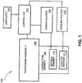
- FIG. 1 illustrates a block diagram of an induction heating compaction system 100 of one embodiment.
- the induction heating compaction system 100 includes a positioning assembly 106 that is coupled to a compaction member 110.
- the positioning assembly 106 is configured to position the compaction member 110 in relation to pre-preg material, as further discussed below.
- the positioning assembly 106 is controlled by a controller 102. Controller 102 controls functions of the induction heating compaction system 100.
- the controller 102 receives commands from a user input 104.
- the compaction member 110 is designed to consolidate plies of the pre-preg material, as further discussed below.
- the compaction member 110 in this embodiment, includes a heating member 112 and a cooling member assembly 111.
- the compaction member 110 of this embodiment has a heating member 112 and a cooling member 111 within its assembly. Placing the heating member 112 and cooling member 111 within the compaction member 110 provides a compact assembly.
- the heating member 112 is an induction heating member that produces an electromagnetic field of a given frequency that heats up the fibers and or matrix in the pre-preg material.
- the heating member 112 is in electrical communication with a power source 108 that provides an energy source for operating the heating members 112.
- the controller 102 controls the power level and time of the energy coming from power source 108.
- the compaction member 110 further includes a cooling assembly 111.
- the cooling assembly 111 may be passive (in that it does not require an external energy source) such as, but not limited to, cooling passages and heat sink material or the cooling member 111 may be an active cooling assembly such as, but not limited to, a fan driven system or a coolant pumping system. If the cooling system is active, the controller 102, in an embodiment, is in communication with a cooling source 109, as shown by dashed lines, that, in turn, regulates cooling levels in the cooling member 111. Example cooling systems are described further below.
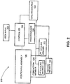
- FIG. 2 illustrates another induction heating compaction system 200. The system 200 is similar to the system 100, described in relation to FIG. 1 . However, in the embodiment of FIG.
- a heating member 122 is positioned proximate the compaction member 120, but not within the compaction member 120.
- This embodiment also illustrates the use of a second cooling member 121 that can be positioned proximate the compaction member 120, but not within the compaction member 120.
- the controller 102 activates the cooling source 109 to provide a cooling medium for the cooling members 111 and 121.
- the cooling members 111 and 121 and/or the heating members 112 ( FIG. 1 ) and 122 include one or more temperature sensors that are used by the controller 102 at least in part to control the amount of heat produced by the heating members 112 and 122, and the amount of cooling provided to the cooling members 111 and 121.
- an in-situ compaction buildup process flow diagram 300 that describes a method of implementing systems of an embodiment is illustrated.
- the process starts by first placing a layer or layers of pre-preg material on a tool surface, or on at least one other ply/plies of pre-preg material that is laid up on a tool (302).
- the layers can be compacted on each other one at a time or several at a time depending on the application and desired outcome.
- the compaction member 120 is then positioned in relation to the pre-preg material (304). Once the compaction member 120 is in the correct position to start compaction, the induction heating member 112 is started (306).
- the induction heating member 112 uses electromagnetic waves of a select power, frequency and time that excites electrons in the conductive fibers and/or conductive components of the matrix of the pre-preg material resulting in the pre-preg being heated up (308). Once the pre-preg material is heated, the compaction member engages the pre-preg material therein, compacting the pre-preg material (310). As the compaction member is compacting the pre-preg material, the compaction member is also pulling heat from the pre-preg material (312).
- the heat, along with the compaction member, allows a tight nesting or consolidation of the plies of pre-preg material and the extracting of the heat by the compaction member solidifies the laminate in a laminated state (i.e., a partially or fully consolidated state, depending on the composite material used in the process).
- a last ply or plies of pre-preg material has been applied at step (314). If it is not the last ply/plies (314), the process continues at step (302) by applying another ply/plies of pre-preg material over the prior laminated and compacted plies on the forming tool at step (302). If it is the last ply/plies (314), the process ends.
- the ply layers can be added in the in-situ process so the ply layers totally cover previously formed ply layers, or subsequent ply layers may only cover portions of previously formed ply layers depending on the desired outcome.
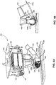
- FIG. 4A An example of an induction heating compaction system 400, of an embodiment, is illustrated in FIG. 4A .
- This embodiment uses a compaction roller 450.
- the induction heating compaction system 400 includes a positioning holding head 402.
- the positioning holding head 402 includes a mounting plate 420 that can be coupled to a further positioning system arm (not shown).
- the mounting plate 420 is coupled to a bracket assembly 422.
- the bracket assembly 422 includes a pivot connection 424 that allows the positioning holding head 402 to be pivoted to position the positioning holding head 402 in a desired orientation.
- Extending from the bracket assembly 422 is a spacer 426.
- the spacer 426 is coupled to one or more actuators 427 that selectively move the spacer 426 up and down.
- a holding bracket 428 is coupled to the spacer 426.
- the holding bracket 428 is designed to hold the compaction roller 450.
- the holding bracket 428 includes a first holding arm 428a and a spaced, second holding arm 428b.
- a roller axle 462 of the compaction roller 450 is coupled between the first and second holding arms 428a and 428b of the holding bracket 428.
- FIG. 4A further illustrates the compaction roller 450 engaging plies of pre-preg material 406 that have been laid up on a forming tool 404.
- FIG. 4A illustrates the compaction ( in-situ ) of a ply layer or ply layers 406a on one or more ply layers 406 that have been laid up on a forming tool 404.
- FIG. 4B illustrates an induction field 440, as depicted by arrows, that is produced by an induction heating member that is housed within the compaction roller 450, as further described in relation to FIG. 6C below.
- the induction field 440 heats ply layer or ply layers 406a.
- heat 447 from the ply layers 406a is extracted back to the compaction roller 450 and the ply layers 406a are solidified in a compact state.
- Compaction roller 450 in this embodiment, includes cooling passages 451 that help maintain the compaction roller 450 in a cool state.
- FIG. 4B further illustrates a temperature sensor 429 positioned to view and sense temperature of material 406a and provide feedback to controller 102 ( FIGS. 1 and 2 ).
- a second induction temperature sensor (not shown) can be used to measure the temperature of a compaction roller cover 452 (see FIG. 6B ) and provide feedback to controller 102.
- a material dispensing member 425 that is designed to dispense and position the one or more ply layers 406a with respect to the roller 450.
- the material dispensing member 425 typically includes the capability to cut and restart the material 406a as needed in the lay-up.
- FIG. 5A Another example embodiment of an induction heater compaction system 500 is illustrated in FIG. 5A .
- a compaction foot 502 (or compaction shoe) is used as the compaction member.
- the compaction foot 502 is coupled to the positioning holding head 402 via the holding bracket 428.
- the compaction foot 502 is coupled between the first and second holding arms 428a and 428b of the holding bracket 428.
- the compaction foot 502 is positioned to compact the plies of pre-preg material 406 positioned on the tool 404.
- the cooling members includes cooling passages 508b.
- the cooling passages 508b in the compaction foot 502 help maintain the compaction foot 502 in a cool state to allow the compaction foot 502 to extract heat from the pre-preg material 406 to solidify the plies in a compacted state.
- roller and foot configuration examples of the compaction member are provided, other configurations can be used and the present invention is not limited to just roller and foot configurations.
- FIG. 5B an illustration of the induction heating compaction system 500 positioned to provide induction heat 530 to the pre-preg material 406 is provided. As illustrated, in this embodiment, the compaction foot 502 is spaced a select distance from the pre-preg material 406 when providing the induction field 530.
- the compaction foot 502 can already be in motion to make contact or already be in contact with the pre-preg material 406 when the induction field 530 is energized.
- the compaction foot 502 of the induction heating compaction system 500 compacts the pre-preg material 406 as illustrated in FIG. 5C .
- the heat 520 being extracted from the pre-preg material 406 into the compaction foot 502 to solidify the pre-preg material 406 in a compact configuration.
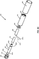
- the compaction roller 450 is further illustrated in FIGS. 6A through 6C .
- FIG. 6A illustrates a front view of the assembled compaction roller 450
- FIG. 6B illustrates a front perspective view of the compaction roller 450
- FIG. 6C illustrates an exploded unassembled view of the compaction roller 450.
- the compaction roller 450 in this embodiment includes, a roller axle 462 that has a cylindrical mid-portion 462a and opposed first and second end portions 462b and 462c.
- the first and second end portions 462b and 462c have smaller diameters than the mid-portion 462a.
- a pair of stub shafts are used instead of the roller axle 462.
- the pair of stubs would function as the first and second end portions 462b and 462c of the roller axle 462.
- a cylindrical shielding 453 is received over the mid-portion 462a of the roller axle 462 in this embodiment.
- the shielding 453 shields at least a portion of the roller axle 462 from the electromagnetic waves generated by an induction heating member 458.
- the shielding 453 is made with electromagnetic wave shielding material.
- the shielding material could be made from thin sheets of copper and/or aluminum or high nickel content foil that is tailored to the frequencies used in the process. For example, the higher the frequency, the thinner the sheets used. Other types of electromagnetic wave shielding material known in the art could also be used.
- the induction heating member 458 is then, in turn, received over the shielding 453.
- a pair of lead wires 457a and 457b that provide energy from a power source to the induction heating member 458 are also illustrated in FIG. 6C .
- a first bearing 456 is received on the first end portion 462b of the roller axle 462.
- the first bearing 456 engages a first shoulder 462d formed between the first end portion 462b and the mid-portion 462a of the roller axle 462.
- a second bearing 464 is received on the second end portion 462c of the roller axle 462.
- the second bearing 464 engages a second shoulder 462e formed between the second end portion 462c and the mid-portion 462a of the roller axle 462.
- a main roller support 454 is received over the roller axle 462.
- the main roller support 454 engages the first and second bearings 456 and 464 such that the main roller support 454 is rotationally coupled to the roller axle 462.
- the main roller support 454 in this embodiment includes a plurality of cooling passages 451, as best seen in FIG. 6B .
- a cooling device 466 is mounted on the second end portion 462c of the roller axle 462.
- the cooling device 466 in this embodiment provides flow of fluids or gas through the plurality of cooling passages 451 in the main roller support 454. In other embodiments, passive cooling may be used and cooling device 466 may not be needed.
- a roller cover 452 is received over the main roller support 454.
- the roller cover 452 is designed to compact ply layers of pre-preg material.
- the roller cover 452 may be solid or a compliant material to conform to the shape being consolidated.
- the roller cover 452 is designed to be replaced.
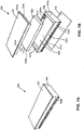
- the compaction foot 502 includes a stamp member 508.
- the stamp member 508, in this embodiment, has a rectangular base portion 507e.
- the stamp member 508 further has opposed first and second end walls 507a and 507b that extend from opposed ends of the rectangular base portion 507e.
- the stamp member 508 also has opposed first and second side walls 507c and 507d that extend from opposed sides of the rectangular base portion 507e.
- the first and second end walls 507a and 507b, the first and second side walls 507c and 507d and the base portion 507e form an inner chamber 509 of the stamp member 508.
- a plurality of cooling passages 508a and 508b extend through the first and second side side walls 507c and 507d of the stamp member 508 and form at least part of a cooling assembly.
- An engaging member 510 (or engaging cover) is coupled to a bottom of the base portion 507e of the stamp member 508.
- the engaging member 510 can be a solid surface or a compliant surface to accommodate local contour.
- the engaging member 510 is covered with a low adherence material for easy release from the pre-preg material.
- the engaging member 510 is designed to engage and compact ply layers of pre-preg material.
- An induction heating member 506 is received in the inner chamber 509 of the stamp member 508.
- lead wires 519a and 519b that deliver power from a power source to the induction heating member 506.
- the compaction foot 502 of this embodiment further includes a shield member 504.
- the shield member 504 includes a shield top cover 504a and a shield side extending portion 504b that extends from the shield top cover 504a to form an inner chamber in which the induction heating member 506 is received.
- the shield side extending portion 504b is, in turn, received in the inner chamber 509 of the stamp member 508.
- the shield top cover 504a covers the inner chamber 509 of the stamp member 508.
- the shield member 504 design may vary with the purpose to protect areas where the induction field is not desirable, and allow it to focus on the material to be compacted.
- the shield member 504 is made from electromagnetic wave shielding material that shields other components from the electromagnetic field generated by the induction heating member 506.
- the compaction foot 502 is made up of sections that move independently to each other so that the compaction feet 502 can walk across the pre-preg material in the in-situ compaction buildup process.
- more than one compaction shoe 502 is used in the in-situ compaction buildup process.
- the compaction shoe 502 is illustrated as being rectangular in shape, the compaction shoe 502 may be any shape that conforms the pre-preg layers to the desired shape of the formed composite structure. The same is true of the compaction roller 450, as discussed above.
Landscapes
- Engineering & Computer Science (AREA)
- Mechanical Engineering (AREA)
- Physics & Mathematics (AREA)
- Health & Medical Sciences (AREA)
- Electromagnetism (AREA)
- Thermal Sciences (AREA)
- Toxicology (AREA)
- Oral & Maxillofacial Surgery (AREA)
- Robotics (AREA)
- Chemical & Material Sciences (AREA)
- Composite Materials (AREA)
- Heating, Cooling, Or Curing Plastics Or The Like In General (AREA)
- Moulding By Coating Moulds (AREA)
- General Induction Heating (AREA)
- Casting Or Compression Moulding Of Plastics Or The Like (AREA)
Description
- Composite products can be made from plies of pre-impregnated (pre-preg) material. Pre-preg material includes fibers surrounded by a matrix material, such as a thermosetting or thermoplastic resin or a ceramic matrix. Consolidation of individual ply layers together to form a composite laminate in a buildup is often critical to the quality of the finished composite product. Lack of compaction within the laminate during lamination, before it sees additional consolidation, such as a cure process, press, or other means, can result in wrinkling of the fibers in the laminate, reducing mechanical performance and affecting dimensional characteristics of the finished product. During consolidation it is common to apply heat to the plies of pre-preg material to heat up the matrix material to make the plies more compliant during consolidation. Typical methods of heating and consolidating composites including using hot gas to flood an area in front of a compaction member, using infrared heat to warm the material in front of a compaction member, and using a laser beam to heat material before it is rolled and compacted. Each of these methods requires space allocation for its heating source and space allocation for its compaction member. Many of these systems are energy and time intensive, or have inherent safety issues when an operator is in close proximity.
- For the reasons stated above and for other reasons stated below that will become apparent to those skilled in the art upon reading and understanding the present specification, there is a need in the art for a safe, effective and efficient system to consolidate plies of pre-preg material.
- Document
DE 10 2007 009 124 A1 discloses an induction-assisted production method for producing molded articles from fiber composites. - Document
WO 2009 130087 A1 discloses a tape installation device and a method for the construction of a laminate by means of a tape installation device, particularly in the aerospace industry. - Document
US 4 992 133 A discloses an apparatus for bonding together at least two composite tapes comprising a tape head, a support surface adjacent the tape head and a supply system for supplying first and second composite tapes between the tape head and the support surface. The tape head includes a heating section and a pressure section pivotally coupled to the heating section. - The above-mentioned problems of current systems are addressed by embodiments of the present invention and will be understood by reading and studying the following specification. The following summary is made by way of example and not by way of limitation. It is merely provided to aid the reader in understanding some of the aspects of the invention.
- The invention is defined according to the subject-matter of the independent claims 1 and 12 as well as the further embodiments disclosed in the dependent claims.
- The present invention can be more easily understood and further advantages and uses thereof will be more readily apparent, when considered in view of the detailed description and the following figures in which:
-
FIG. 1 is a block diagram of an induction heating compaction system of one embodiment of the present invention; -
FIG. 2 is a block diagram of another induction heating compaction system of one embodiment of the present invention; -
FIG. 3 is an in-situ compaction buildup process flow diagram of one embodiment of the present invention; -
FIG. 4A is a side perspective view of an induction heating compaction system of one embodiment of the present invention; -
FIG. 4B is a side view of a portion of the induction heating compaction system ofFIG. 4A ; -
FIG. 5A is a side perspective view of another induction heating compaction system of one embodiment of the present invention; -
FIG. 5B is a side perspective view of the induction heating compaction system ofFIG. 5A ; -
FIG. 5C is a side perspective view of the induction heating compaction system ofFIG. 5A ; -
FIG. 6A is a front view of an induction heating compaction roller used in the induction heating compaction system ofFIG. 4A ; -
FIG. 6B is a front perspective view of the induction heating compaction roller ofFIG. 6A ; -
FIG. 6C is a front perspective exploded view of the induction heating compaction roller ofFIG. 6A ; -
FIG. 7A is a side perspective view of an induction heating compaction foot used in the induction heating compaction system ofFIG. 5A ; and -
FIG. 7B is a side perspective exploded view of the induction heating compaction foot ofFIG. 7A . - In accordance with common practice, the various described features are not drawn to scale but are drawn to emphasize specific features relevant to the present invention. Reference characters denote like elements throughout the figures and the specification.
- In the following detailed description, reference is made to the accompanying drawings, which form a part hereof, and in which is shown by way of illustration specific embodiments in which the inventions may be practiced. These embodiments are described in sufficient detail to enable those skilled in the art to practice the invention, and it is to be understood that other embodiments may be utilized and that changes may be made without departing from the scope of the invention as defined by the appended claims. The following detailed description is, therefore, not to be taken in a limiting sense, and the scope of the present invention is defined only by the claims and equivalents thereof.
- One benefit of some embodiments of the present invention is that they provide an induction heating compaction system that is relatively compact to save space and make packaging easier. A tighter package allows more contour capability within automation systems. In an embodiment of the present invention, induction heating is used to heat conductive fibers in pre-preg material that, in turn, melts or softens the surrounding matrix to allow tight nesting or consolidation of one ply to a previous laid ply or plies, generally known as an "on-the-fly" or "in-situ" process. An example type of conductive fiber used in the pre-preg material is carbon fiber. Since carbon fiber is conductive, it will heat up when subjected to an alternating electromagnetic field of a given frequency, provided by an induction heater assembly. Besides conductive fibers, non-conductive fibers that are metallically coated could be used. In other embodiments, the matrix is formulated to react directly to the induction heating. In these embodiments, the matrix may be loaded with conductive particles. The conductive particles could be metallic, carbon nanofibers, nanofillers, etc. The conductivity components of the matrix would absorb the induction heating and soften the pre-preg. In yet another embodiment, both the fiber and matrix may react to the induction heating.
- A compaction member is then used to compact the plies while still warm\hot as part of the in-situ compaction buildup process. The compaction member, of embodiments, extracts heat from the pre-preg material while compacting the lamina or laminate in a consolidated or cured state. In some embodiments, the compaction member is actively cooled for higher temperature materials or to allow faster process speeds. In embodiments, portions of a compaction member, particularly in the "field of view," so to speak, of the induction field directed toward the composite material, are made from a material that is not affected by the select frequency of the electromagnetic field used to heat up the composite pre-preg material. Hence, in some embodiments, at least a portion of the compaction member is made from material that is transparent to the frequency of the electromagnetic field created by the induction heating member. Moreover, in some embodiments, at least some portions of the compaction member that are not transparent to the frequency of the electromagnetic field are shielded from the induction field.
-
FIG. 1 illustrates a block diagram of an inductionheating compaction system 100 of one embodiment. The inductionheating compaction system 100 includes apositioning assembly 106 that is coupled to acompaction member 110. Thepositioning assembly 106 is configured to position thecompaction member 110 in relation to pre-preg material, as further discussed below. Thepositioning assembly 106 is controlled by acontroller 102.Controller 102 controls functions of the inductionheating compaction system 100. Thecontroller 102 receives commands from auser input 104. Thecompaction member 110 is designed to consolidate plies of the pre-preg material, as further discussed below. Thecompaction member 110, in this embodiment, includes aheating member 112 and a coolingmember assembly 111. That is, thecompaction member 110 of this embodiment has aheating member 112 and a coolingmember 111 within its assembly. Placing theheating member 112 and coolingmember 111 within thecompaction member 110 provides a compact assembly. In embodiments, as discussed above, theheating member 112 is an induction heating member that produces an electromagnetic field of a given frequency that heats up the fibers and or matrix in the pre-preg material. Theheating member 112 is in electrical communication with apower source 108 that provides an energy source for operating theheating members 112. In one embodiment, thecontroller 102 controls the power level and time of the energy coming frompower source 108. As discussed above, thecompaction member 110 further includes acooling assembly 111. The coolingassembly 111 may be passive (in that it does not require an external energy source) such as, but not limited to, cooling passages and heat sink material or the coolingmember 111 may be an active cooling assembly such as, but not limited to, a fan driven system or a coolant pumping system. If the cooling system is active, thecontroller 102, in an embodiment, is in communication with acooling source 109, as shown by dashed lines, that, in turn, regulates cooling levels in the coolingmember 111. Example cooling systems are described further below.FIG. 2 illustrates another inductionheating compaction system 200. Thesystem 200 is similar to thesystem 100, described in relation toFIG. 1 . However, in the embodiment ofFIG. 2 , a heating member 122 is positioned proximate thecompaction member 120, but not within thecompaction member 120. This embodiment, also illustrates the use of asecond cooling member 121 that can be positioned proximate thecompaction member 120, but not within thecompaction member 120. In embodiments, thecontroller 102 activates thecooling source 109 to provide a cooling medium for the coolingmembers members FIG. 1 ) and 122 include one or more temperature sensors that are used by thecontroller 102 at least in part to control the amount of heat produced by theheating members 112 and 122, and the amount of cooling provided to the coolingmembers - Referring to
FIG. 3 , an in-situ compaction buildup process flow diagram 300 that describes a method of implementing systems of an embodiment is illustrated. The process starts by first placing a layer or layers of pre-preg material on a tool surface, or on at least one other ply/plies of pre-preg material that is laid up on a tool (302). In embodiments, the layers can be compacted on each other one at a time or several at a time depending on the application and desired outcome. Thecompaction member 120 is then positioned in relation to the pre-preg material (304). Once thecompaction member 120 is in the correct position to start compaction, theinduction heating member 112 is started (306). Theinduction heating member 112 uses electromagnetic waves of a select power, frequency and time that excites electrons in the conductive fibers and/or conductive components of the matrix of the pre-preg material resulting in the pre-preg being heated up (308). Once the pre-preg material is heated, the compaction member engages the pre-preg material therein, compacting the pre-preg material (310). As the compaction member is compacting the pre-preg material, the compaction member is also pulling heat from the pre-preg material (312). Accordingly, the heat, along with the compaction member, allows a tight nesting or consolidation of the plies of pre-preg material and the extracting of the heat by the compaction member solidifies the laminate in a laminated state (i.e., a partially or fully consolidated state, depending on the composite material used in the process). In the compaction flow diagram 300 embodiment, it is then determined if a last ply or plies of pre-preg material has been applied at step (314). If it is not the last ply/plies (314), the process continues at step (302) by applying another ply/plies of pre-preg material over the prior laminated and compacted plies on the forming tool at step (302). If it is the last ply/plies (314), the process ends. In embodiments, the ply layers can be added in the in-situ process so the ply layers totally cover previously formed ply layers, or subsequent ply layers may only cover portions of previously formed ply layers depending on the desired outcome. - An example of an induction
heating compaction system 400, of an embodiment, is illustrated inFIG. 4A . This embodiment uses acompaction roller 450. Moreover, the inductionheating compaction system 400 includes apositioning holding head 402. Thepositioning holding head 402 includes a mountingplate 420 that can be coupled to a further positioning system arm (not shown). The mountingplate 420 is coupled to abracket assembly 422. Thebracket assembly 422 includes apivot connection 424 that allows thepositioning holding head 402 to be pivoted to position thepositioning holding head 402 in a desired orientation. Extending from thebracket assembly 422 is aspacer 426. Thespacer 426 is coupled to one ormore actuators 427 that selectively move thespacer 426 up and down. A holdingbracket 428 is coupled to thespacer 426. The holdingbracket 428 is designed to hold thecompaction roller 450. In particular, the holdingbracket 428 includes afirst holding arm 428a and a spaced,second holding arm 428b. Aroller axle 462 of thecompaction roller 450 is coupled between the first and second holdingarms bracket 428.FIG. 4A further illustrates thecompaction roller 450 engaging plies ofpre-preg material 406 that have been laid up on a formingtool 404. In particular,FIG. 4A illustrates the compaction (in-situ) of a ply layer or plylayers 406a on one ormore ply layers 406 that have been laid up on a formingtool 404. Referring to the side view illustrated inFIG. 4B , a description of the induction heating and heat transfer is provided. In particular,FIG. 4B illustrates aninduction field 440, as depicted by arrows, that is produced by an induction heating member that is housed within thecompaction roller 450, as further described in relation toFIG. 6C below. Theinduction field 440 heats ply layer or plylayers 406a. As thecompaction roller 450 engages theply layers 406a, heat 447 from theply layers 406a is extracted back to thecompaction roller 450 and theply layers 406a are solidified in a compact state.Compaction roller 450, in this embodiment, includes coolingpassages 451 that help maintain thecompaction roller 450 in a cool state.FIG. 4B further illustrates atemperature sensor 429 positioned to view and sense temperature ofmaterial 406a and provide feedback to controller 102 (FIGS. 1 and2 ). A second induction temperature sensor (not shown) can be used to measure the temperature of a compaction roller cover 452 (seeFIG. 6B ) and provide feedback tocontroller 102. Also illustrated inFIGS. 4A and 4B is amaterial dispensing member 425 that is designed to dispense and position the one ormore ply layers 406a with respect to theroller 450. Thematerial dispensing member 425 typically includes the capability to cut and restart thematerial 406a as needed in the lay-up. - Another example embodiment of an induction
heater compaction system 500 is illustrated inFIG. 5A . In the inductionheating compaction system 500, a compaction foot 502 (or compaction shoe) is used as the compaction member. In this embodiment, thecompaction foot 502 is coupled to thepositioning holding head 402 via the holdingbracket 428. In particular, thecompaction foot 502 is coupled between the first and second holdingarms bracket 428. As illustrated inFIG. 5A , thecompaction foot 502 is positioned to compact the plies ofpre-preg material 406 positioned on thetool 404. In this embodiment, the cooling members includes coolingpassages 508b. Thecooling passages 508b in thecompaction foot 502 help maintain thecompaction foot 502 in a cool state to allow thecompaction foot 502 to extract heat from thepre-preg material 406 to solidify the plies in a compacted state. Although only roller and foot configuration examples of the compaction member are provided, other configurations can be used and the present invention is not limited to just roller and foot configurations. Referring toFIG. 5B , an illustration of the inductionheating compaction system 500 positioned to provideinduction heat 530 to thepre-preg material 406 is provided. As illustrated, in this embodiment, thecompaction foot 502 is spaced a select distance from thepre-preg material 406 when providing theinduction field 530. In other embodiments, thecompaction foot 502 can already be in motion to make contact or already be in contact with thepre-preg material 406 when theinduction field 530 is energized. Once thepre-preg material 406 has been heated, thecompaction foot 502 of the inductionheating compaction system 500 compacts thepre-preg material 406 as illustrated inFIG. 5C . Also illustrated inFIG. 5C is theheat 520 being extracted from thepre-preg material 406 into thecompaction foot 502 to solidify thepre-preg material 406 in a compact configuration. - The
compaction roller 450 is further illustrated inFIGS. 6A through 6C . In particular,FIG. 6A illustrates a front view of the assembledcompaction roller 450,FIG. 6B illustrates a front perspective view of thecompaction roller 450, andFIG. 6C illustrates an exploded unassembled view of thecompaction roller 450. Referring toFIG. 6C , thecompaction roller 450 in this embodiment includes, aroller axle 462 that has acylindrical mid-portion 462a and opposed first andsecond end portions second end portions roller axle 462. The pair of stubs would function as the first andsecond end portions roller axle 462. Acylindrical shielding 453 is received over the mid-portion 462a of theroller axle 462 in this embodiment. The shielding 453 shields at least a portion of theroller axle 462 from the electromagnetic waves generated by aninduction heating member 458. In an embodiment, the shielding 453 is made with electromagnetic wave shielding material. For example, the shielding material could be made from thin sheets of copper and/or aluminum or high nickel content foil that is tailored to the frequencies used in the process. For example, the higher the frequency, the thinner the sheets used. Other types of electromagnetic wave shielding material known in the art could also be used. Theinduction heating member 458 is then, in turn, received over the shielding 453. A pair oflead wires induction heating member 458 are also illustrated inFIG. 6C . Afirst bearing 456 is received on thefirst end portion 462b of theroller axle 462. Thefirst bearing 456 engages afirst shoulder 462d formed between thefirst end portion 462b and the mid-portion 462a of theroller axle 462. Asecond bearing 464 is received on thesecond end portion 462c of theroller axle 462. Thesecond bearing 464 engages asecond shoulder 462e formed between thesecond end portion 462c and the mid-portion 462a of theroller axle 462. Amain roller support 454 is received over theroller axle 462. Themain roller support 454 engages the first andsecond bearings main roller support 454 is rotationally coupled to theroller axle 462. Themain roller support 454 in this embodiment includes a plurality of coolingpassages 451, as best seen inFIG. 6B . Further, in this embodiment, acooling device 466 is mounted on thesecond end portion 462c of theroller axle 462. Thecooling device 466 in this embodiment provides flow of fluids or gas through the plurality of coolingpassages 451 in themain roller support 454. In other embodiments, passive cooling may be used andcooling device 466 may not be needed. Aroller cover 452 is received over themain roller support 454. Theroller cover 452 is designed to compact ply layers of pre-preg material. Theroller cover 452 may be solid or a compliant material to conform to the shape being consolidated. Moreover, in some embodiments, theroller cover 452 is designed to be replaced. - An embodiment that uses a compaction foot (or shoe) 502 is illustrated in the assembled side perspective view of
FIG. 7A and the exploded (unassembled) side perspective view ofFIG. 7B . Thecompaction foot 502 includes astamp member 508. Thestamp member 508, in this embodiment, has arectangular base portion 507e. Thestamp member 508 further has opposed first andsecond end walls rectangular base portion 507e. Thestamp member 508 also has opposed first andsecond side walls rectangular base portion 507e. The first andsecond end walls second side walls base portion 507e form aninner chamber 509 of thestamp member 508. A plurality ofcooling passages side side walls stamp member 508 and form at least part of a cooling assembly. An engaging member 510 (or engaging cover) is coupled to a bottom of thebase portion 507e of thestamp member 508. The engagingmember 510 can be a solid surface or a compliant surface to accommodate local contour. In one embodiment, the engagingmember 510 is covered with a low adherence material for easy release from the pre-preg material. The engagingmember 510 is designed to engage and compact ply layers of pre-preg material. Aninduction heating member 506 is received in theinner chamber 509 of thestamp member 508. Also shown inFIG. 7B , arelead wires induction heating member 506. Thecompaction foot 502 of this embodiment further includes ashield member 504. Theshield member 504 includes ashield top cover 504a and a shieldside extending portion 504b that extends from theshield top cover 504a to form an inner chamber in which theinduction heating member 506 is received. The shieldside extending portion 504b is, in turn, received in theinner chamber 509 of thestamp member 508. Theshield top cover 504a covers theinner chamber 509 of thestamp member 508. Theshield member 504 design may vary with the purpose to protect areas where the induction field is not desirable, and allow it to focus on the material to be compacted. Hence, theshield member 504 is made from electromagnetic wave shielding material that shields other components from the electromagnetic field generated by theinduction heating member 506. In other embodiments, thecompaction foot 502 is made up of sections that move independently to each other so that thecompaction feet 502 can walk across the pre-preg material in the in-situ compaction buildup process. Moreover, in other embodiments more than onecompaction shoe 502 is used in the in-situ compaction buildup process. In addition, although thecompaction shoe 502 is illustrated as being rectangular in shape, thecompaction shoe 502 may be any shape that conforms the pre-preg layers to the desired shape of the formed composite structure. The same is true of thecompaction roller 450, as discussed above. - Although specific embodiments have been illustrated and described herein, it will be appreciated by those of ordinary skill in the art that any arrangement, which is calculated to achieve the same purpose, may be substituted for the specific embodiments shown. This application is intended to cover any adaptations or variations of the present invention. Therefore, it is manifestly intended that this invention be limited only by the claims.
Claims (16)
- An induction heating compaction system (100, 200, 400, 500), the system comprising:
a compaction member (110, 120, 450, 502) comprising one of a compaction roller (450) or a compaction foot (502) for engaging pre-preg material, the compaction member (110, 120, 450, 502) configured and arranged to extract heat from the pre-preg material in-situ while compacting the pre-preg material that has been laid up and positioned over a surface of a forming tool, the compaction member (110, 120, 450, 502) comprising:an induction heating member (112, 122, 458, 506) received within the one of the compaction roller (450) or the compaction foot (502), the induction heating member (112, 122, 458, 506) configured to generate an electromagnetic field at a select frequency, the select frequency for heating at least one of the fibers and matrix in pre-preg material, wherein the induction heating member is contained within the compaction member (110, 120, 450, 502), the compaction member (110, 120, 450, 502) having at least one portion that is made from a material that is transparent to the select frequency of the electromagnetic field generated by the induction heating member (112, 122, 458, 506) enabling the electromagnetic field to be directed at a composite pre-preg material to be consolidated while not heating up the at least one portion of the compaction member (110, 120, 450, 502); anda cooling assembly (111, 122, 451, 466, 508) received within the one of the compaction roller (450) or the compaction foot (502), the cooling assembly (111, 122, 451, 466, 508) configured and arranged to extract heat energy from the pre-preg material to solidify the ply layers of pre-preg material in a compact configuration during an in-situ compaction buildup process. - The system of claim 1, further comprising:
at least one shielding member (453, 504) positioned to shield at least one reactive portion of the compaction member (110, 120, 450, 502) that is not transparent to the electromagnetic field generated by the induction heating member (112, 122, 458, 506) from the heating effects of the induction field. - The system of claim 1, wherein the compaction member (110, 120, 450, 502) is the compaction roller (450).
- The system of claim 3, wherein the compaction roller (450) further comprises:a roller axle (462) having opposed first and second end portions;a cylindrical shielding (453) configured and arranged to be received over the roller axle (462);an induction heating member (112, 122, 458, 506) configured and arranged to be received over the shielding (453);a first bearing (456, 464) received on the first end portion of the roller axle (462);a second bearing (456, 464) received on the second end portion of the roller axle (462);a main roller support (454) received over the roller axle (462) and engaging the first and second bearings (456, 464) such that the main roller support (454) is rotationally coupled to the roller axle (462); anda roller cover (452) received over the main roller support (454), the roller cover (452) configured and arranged to compact composite pre-preg material.
- The system of claim 4, further comprising:the roller axis further having a cylindrical mid-portion between the opposed first and second end portions, the first and second end portions having a smaller diameter than the mid-portion;the cylindrical shielding (453) received over the mid-portion of the roller axis;the first bearing (456, 464) engaging a first shoulder formed between the first end portion and mid-portion of the roller axle (462);the second bearing (456, 464) engaging a second shoulder formed between the second end portion and mid-portion of the roller axle (462); andthe main roller support (454) including a plurality of cooling passages (451, 508).
- The system of claim 5, wherein the cooling assembly (111, 122, 451, 466, 508) comprises a cooling device (466) configured and arranged to provide a flow for at least one of a gas or liquid through the plurality of cooling passages (451, 508) in the main roller support (454).
- The system of claim 1, wherein the compaction member (110, 120, 450, 502) is the compaction foot (502).
- The system of claim 7, wherein the compaction foot (502) further comprises:a stamp member (508), the stamp member (508) including at least one base portion, opposed first and second end walls (507a, 507b) extending from opposed ends of the at least one base portion (507e), opposed first and second side walls (507c, 507d) extending from opposed sides of the base portion (507e), the first and second end walls (507a, 507b), the first and second side walls (507c, 507d) and the base portion (507e) forming an inner chamber (509) of the stamp member (508);an engaging member (510) coupled to a bottom of the base portion (507e) of the stamp member (508), the engaging member (510) configured and arranged to compact pre-preg material; andan induction heating member (112, 122, 458, 506) received in the inner chamber (509) of the stamp member (508).
- The system of claim 8, further comprising:the first and second side walls (507c, 507d) having a plurality of cooling passages (451, 508); anda shield member (504), the shield member (504) including a shield top cover (504a) and shield side portions (504b) that extend from the shield top cover (504a), the shield side portions (504b) received in the inner chamber (509) of the stamp member (508), the shield top cover (504a) configured and arranged to cover the inner chamber (509) of the stamp member (508).
- The system of claim 1, further comprising:
a positioning assembly (106, 402) configured and arranged to position the compaction member (110, 120, 450, 502) in a desired location. - The system of claim 10, further comprising a controller (102) coupled to control the positioning assembly (106, 402), wherein the controller (102) is further configured to control the heating, compaction and cooling of the pre-preg material to a solidified state as the system (100, 200, 400, 500) passes over the material in a continuous compaction process.
- A method of consolidating pre-preg material ply layers, the method comprising:inductively heating an area of at least one of fibers and matrix in at least one first pre-preg material ply layer laid up over a surface of a forming tool to soften the matrix in the heated area with an induction heating member (112, 122, 458, 506) of one of a compaction roller (450) or a compaction foot (502) of a compaction member (110, 120, 450, 502);engaging the at least one first pre-preg material ply layer with the one of a compaction roller (450) or a compaction foot (502) of the compaction member (110, 120, 450, 502);compacting the heated area of the at least one first pre-preg material ply layer during layup of the at least one first pre-preg material ply layer over a second pre-preg material ply layer with the one of a compaction roller (450) or a compaction foot (502) of the compaction member (110, 120, 450, 502); andextracting heat energy from the at least one first pre-preg material ply layer and the second pre-preg material layer with a cooling assembly (111, 122, 451, 466, 508) positioned within the one of a compaction roller (450) or a compaction foot (502) of the compaction member (110, 120, 450, 502) while compacting the heated area with the compaction member (110, 120, 450, 502) to solidify the at least one first pre-preg material layer and the second pre-preg material ply layer in a compact state.
- The method of claim 12, further comprising:automatically laying up at least a portion of the first pre-preg material ply layer over the at least one second pre-preg material ply layer;inductively heating at least one of fibers and matrix in the at least a portion of the first pre-preg material ply layer to soften the matrix in the at least a portion of the first pre-preg material ply layer;compacting the at least a portion of the first pre-preg material ply layer over the at least one second pre-preg material ply layer; andextracting heat energy from the at least a portion of the first pre-preg material layer and the at least one second pre-preg material ply layer during the compacting to solidify the ply layers in a compact state.
- The method of claim 12, further comprising:
generating induction heat energy of a given frequency that heats up at least one of the fibers and matrix in the at least one first pre-preg material ply layer with an induction heater (112, 122, 458, 506) housed within the compaction member (110, 120, 450, 502). - The method of claim 12, further comprising:
shielding at least some elements of the compaction member (110, 120, 450, 502) from the heating effects of the induction heating member (112, 122, 458, 506). - The method of claim 12, further comprising:
cooling the compaction member (110, 120, 450, 502) that compacts the heated area to extract the heat energy from the at least one first pre-preg material ply layer and the second pre-preg material ply layer.
Applications Claiming Priority (2)
| Application Number | Priority Date | Filing Date | Title |
|---|---|---|---|
| US13/734,661 US9527237B2 (en) | 2013-01-04 | 2013-01-04 | Induction heating compaction system |
| PCT/US2014/010138 WO2014107555A1 (en) | 2013-01-04 | 2014-01-03 | Induction heating compaction system and method of compacting |
Publications (2)
| Publication Number | Publication Date |
|---|---|
| EP2941343A1 EP2941343A1 (en) | 2015-11-11 |
| EP2941343B1 true EP2941343B1 (en) | 2020-07-22 |
Family
ID=50000111
Family Applications (1)
| Application Number | Title | Priority Date | Filing Date |
|---|---|---|---|
| EP14701134.0A Active EP2941343B1 (en) | 2013-01-04 | 2014-01-03 | Induction heating compaction system and method of compacting |
Country Status (8)
| Country | Link |
|---|---|
| US (2) | US9527237B2 (en) |
| EP (1) | EP2941343B1 (en) |
| JP (2) | JP6465304B2 (en) |
| KR (1) | KR102001406B1 (en) |
| CN (1) | CN104995014B (en) |
| CA (1) | CA2897194C (en) |
| ES (1) | ES2821749T3 (en) |
| WO (1) | WO2014107555A1 (en) |
Families Citing this family (31)
| Publication number | Priority date | Publication date | Assignee | Title |
|---|---|---|---|---|
| US20140262008A1 (en) * | 2013-03-15 | 2014-09-18 | Apple Inc. | Heated roller head bonding process |
| US11510290B2 (en) * | 2014-05-16 | 2022-11-22 | Illinois Tool Works Inc. | Induction heating system |
| EP2952316B1 (en) * | 2014-06-03 | 2017-10-11 | Airbus Defence and Space GmbH | Fibre application tool, fibre laying device, fibre laying method and production method |
| DE102015008313A1 (en) * | 2015-06-30 | 2017-01-05 | Airbus Defence and Space GmbH | Device and method |
| JP6697819B2 (en) * | 2016-04-21 | 2020-05-27 | 三菱重工業株式会社 | Composite material forming apparatus and composite material forming method |
| DE102017212068B4 (en) | 2017-07-14 | 2021-03-18 | Airbus Defence and Space GmbH | Fiber composite laying device and fiber composite laying method for the production of a fiber composite fabric for the formation of a fiber composite component |
| JP7049613B2 (en) * | 2018-01-31 | 2022-04-07 | 三菱重工業株式会社 | Pressurized head, composite material molding equipment and composite material molding method |
| DE102018115392B4 (en) * | 2018-06-26 | 2022-09-22 | Azl Aachen Gmbh | Process and device for the production of workpieces having fiber composite material |
| US11883987B2 (en) * | 2018-07-10 | 2024-01-30 | Desktop Metal, Inc. | Systems and methods relating to 3D printing composite structures |
| DE102018116662A1 (en) * | 2018-07-10 | 2020-01-16 | Deutsches Zentrum für Luft- und Raumfahrt e.V. | Fiber laying plant and method for depositing fiber material |
| IT201800020524A1 (en) * | 2018-12-20 | 2020-06-20 | Leonardo Spa | ELECTROMAGNETIC INDUCTION WELDING DEVICE FOR JOINING COMPOSITE MATERIALS AND RELATIVE JOINT METHOD |
| JP7217457B2 (en) * | 2019-01-29 | 2023-02-03 | 三菱重工業株式会社 | Composite material molding method |
| US11214022B2 (en) * | 2019-02-28 | 2022-01-04 | The Boeing Company | Active cooling system for manufacturing composite structures |
| JP7686948B2 (en) * | 2019-07-12 | 2025-06-03 | 東レ株式会社 | Tape application device, tape application method, and method for manufacturing composite molded product |
| US11292204B2 (en) | 2019-08-06 | 2022-04-05 | The Boeing Company | Induction welding using a heat sink and/or cooling |
| US11358344B2 (en) | 2019-08-06 | 2022-06-14 | The Boeiog Company | Induction welding using a heat sink and/or cooling |
| US11458691B2 (en) | 2019-08-06 | 2022-10-04 | The Boeing Company | Induction welding using a heat sink and/or cooling |
| US11230066B2 (en) | 2019-08-06 | 2022-01-25 | The Boeing Company | Induction welding using a heat sink and/or cooling |
| US11364688B2 (en) * | 2019-08-06 | 2022-06-21 | The Boeing Company | Induction welding using a heat sink and/or cooling |
| US11351738B2 (en) | 2019-08-06 | 2022-06-07 | The Boeing Company | Induction welding using a heat sink and/or cooling |
| US11524467B2 (en) | 2019-08-06 | 2022-12-13 | The Boeing Company | Induction welding using a heat sink and/or cooling |
| JP7434864B2 (en) * | 2019-12-06 | 2024-02-21 | 富士フイルムビジネスイノベーション株式会社 | modeling equipment |
| US12551968B2 (en) * | 2020-03-20 | 2026-02-17 | Wichita State University | Systems and methods for induction welding |
| FR3119561A1 (en) * | 2021-02-05 | 2022-08-12 | Arkema France | METHOD FOR PREPARING COMPOSITE PARTS WITH A HIGH DEGREE OF CONSOLIDATION |
| FR3120008B1 (en) * | 2021-02-22 | 2024-03-15 | Airbus Operations Sas | Device for consolidating a part made of composite material by induction heating |
| US20230381883A1 (en) * | 2022-05-24 | 2023-11-30 | Rohr, Inc. | Induction welding heat shield assembly with multiple heat shields with aligned recesses for induction welding path |
| US12434321B2 (en) | 2022-05-24 | 2025-10-07 | Rohr, Inc. | Ceramic coating heat shield for induction welding |
| US12391010B2 (en) | 2023-01-13 | 2025-08-19 | Rtx Corporation | Methods of manufacture for composite blades |
| US12485623B2 (en) * | 2023-07-31 | 2025-12-02 | Rohr, Inc. | Induction welding thermoplastic material with different electrical conductivities |
| NL2036866B1 (en) * | 2024-01-22 | 2025-08-01 | Boeing Co | Systems and Methods for Compacting Ceramic Composite Materials |
| EP4563311A1 (en) | 2023-11-29 | 2025-06-04 | The Boeing Company | Systems and methods for compacting ceramic composite materials |
Family Cites Families (29)
| Publication number | Priority date | Publication date | Assignee | Title |
|---|---|---|---|---|
| US4410385A (en) * | 1981-01-28 | 1983-10-18 | General Electric Company | Method of making a composite article |
| US4714509A (en) | 1984-07-02 | 1987-12-22 | E. I. Dupont De Nemours And Company | Method and apparatus for laying down tapes |
| US4822444A (en) | 1986-04-25 | 1989-04-18 | Rohr Industries, Inc. | Filament winding mechanism for forming and winding a shingled gap free band |
| US4883552A (en) | 1986-12-05 | 1989-11-28 | Phillips Petroleum Company | Pultrusion process and apparatus |
| US5160561A (en) | 1987-09-11 | 1992-11-03 | E. I. Du Pont De Nemours And Company | Method for winding a plurality of lengths of thermoplastic resin impregnated yarns using a heated guide eye |
| US5160568A (en) | 1987-09-11 | 1992-11-03 | E. I. Du Pont De Nemours And Company | Apparatus including a heated guide eye for winding a plurality of lengths of thermoplastic resin impregnated yarns |
| US4992133A (en) | 1988-09-30 | 1991-02-12 | Pda Engineering | Apparatus for processing composite materials |
| US5177340A (en) | 1989-01-23 | 1993-01-05 | Cincinnati Milacron Inc. | Control of radiant heating system for thermoplastic composite tape |
| US4978825A (en) * | 1989-11-08 | 1990-12-18 | Northrop Corporation | Thermoplastic composite induction welder |
| US5205898A (en) * | 1990-11-15 | 1993-04-27 | The United States Of America As Represented By The Administrator Of The National Aeronautics And Space Administration | Continuous fiber thermoplastic prepreg |
| US5200018A (en) | 1990-12-19 | 1993-04-06 | Hercules Incorporated | Ribbonizing apparatus for individually heating a plurality of laterally adjacent tows in a fiber placement device |
| US5273602A (en) | 1990-12-19 | 1993-12-28 | Hercules Incorporated | Ribbonizing method for selectively heating a respective one of a plurality of fiber tows |
| US5338497A (en) | 1992-04-03 | 1994-08-16 | Ford Motor Company | Induction heating method for forming composite articles |
| EP0644040A1 (en) | 1993-05-27 | 1995-03-22 | Cincinnati Milacron Inc. | Method of and apparatus for laying composite material |
| US5447586A (en) | 1994-07-12 | 1995-09-05 | E. I. Du Pont De Nemours And Company | Control of thermoplastic tow placement |
| US5587041A (en) * | 1995-03-21 | 1996-12-24 | The United States Of America As Represented By The Administrator Of The National Aeronautics And Space Administration | Composite prepreg application device |
| US5832354A (en) * | 1995-12-05 | 1998-11-03 | Ricoh Company, Ltd. | Image fixing device, image forming apparatus providing the image fixing device and rotor used in the image fixing device and having induction coil inside |
| EP1132193A1 (en) | 2000-02-25 | 2001-09-12 | Abb Research Ltd. | Apparatus and method for arranging and bonding a prestressed fiber array on a surface |
| US6799619B2 (en) | 2002-02-06 | 2004-10-05 | The Boeing Company | Composite material collation machine and associated method for high rate collation of composite materials |
| JP2005297513A (en) * | 2004-04-16 | 2005-10-27 | Fuji Heavy Ind Ltd | Automatic laminator |
| FR2882681B1 (en) * | 2005-03-03 | 2009-11-20 | Coriolis Composites | FIBER APPLICATION HEAD AND CORRESPONDING MACHINE |
| US7731816B2 (en) | 2006-02-16 | 2010-06-08 | Ingersoll Machine Tools, Inc. | System and method for heating carbon fiber using infrared radiation in a fiber placement machine |
| US7993124B2 (en) | 2006-12-28 | 2011-08-09 | The Boeing Company | Heating apparatus for a composite laminator and method |
| DE102007009124B4 (en) * | 2007-02-24 | 2011-11-03 | Evonik Degussa Gmbh | Induction-based manufacturing processes |
| DE102008020564B4 (en) * | 2008-04-24 | 2013-10-02 | Airbus Operations Gmbh | Tape laying device and method for building a laminate |
| US9063000B2 (en) * | 2009-05-15 | 2015-06-23 | Glaxosmithkline Llc | Using thermal imaging for control of a manufacturing process |
| FR2948058B1 (en) * | 2009-07-17 | 2011-07-22 | Coriolis Composites | FIBER APPLICATION MACHINE COMPRISING A FLEXIBLE COMPACTION ROLL WITH THERMAL CONTROL SYSTEM |
| DE102010023044A1 (en) | 2010-06-08 | 2011-01-27 | Daimler Ag | Manufacturing fiber preform for composite component, involves storing fiber bundles of carbon fibers by using fixing device in predetermined space on substrate |
| US8527268B2 (en) * | 2010-06-30 | 2013-09-03 | Rovi Technologies Corporation | Method and apparatus for improving speech recognition and identifying video program material or content |
-
2013
- 2013-01-04 US US13/734,661 patent/US9527237B2/en active Active
-
2014
- 2014-01-03 WO PCT/US2014/010138 patent/WO2014107555A1/en not_active Ceased
- 2014-01-03 EP EP14701134.0A patent/EP2941343B1/en active Active
- 2014-01-03 ES ES14701134T patent/ES2821749T3/en active Active
- 2014-01-03 KR KR1020157021016A patent/KR102001406B1/en active Active
- 2014-01-03 JP JP2015551767A patent/JP6465304B2/en active Active
- 2014-01-03 CN CN201480008588.3A patent/CN104995014B/en active Active
- 2014-01-03 CA CA2897194A patent/CA2897194C/en active Active
-
2016
- 2016-11-03 US US15/342,998 patent/US20170080647A1/en not_active Abandoned
-
2018
- 2018-09-27 JP JP2018182129A patent/JP6689342B2/en active Active
Non-Patent Citations (1)
| Title |
|---|
| None * |
Also Published As
| Publication number | Publication date |
|---|---|
| JP6689342B2 (en) | 2020-04-28 |
| CN104995014A (en) | 2015-10-21 |
| US20170080647A1 (en) | 2017-03-23 |
| KR20150103263A (en) | 2015-09-09 |
| JP2019024012A (en) | 2019-02-14 |
| US9527237B2 (en) | 2016-12-27 |
| CN104995014B (en) | 2018-06-05 |
| US20140190629A1 (en) | 2014-07-10 |
| JP6465304B2 (en) | 2019-02-06 |
| KR102001406B1 (en) | 2019-07-18 |
| ES2821749T3 (en) | 2021-04-27 |
| EP2941343A1 (en) | 2015-11-11 |
| JP2016508085A (en) | 2016-03-17 |
| WO2014107555A1 (en) | 2014-07-10 |
| CA2897194C (en) | 2018-09-25 |
| CA2897194A1 (en) | 2014-07-10 |
Similar Documents
| Publication | Publication Date | Title |
|---|---|---|
| CA2897194C (en) | Induction heating compaction system and related methods | |
| KR102434956B1 (en) | Systems and methods for additively manufacturing composite parts | |
| US8865050B2 (en) | Method for curing a composite part layup | |
| US10751954B2 (en) | Automated fiber placement and in-situ fiber impregnation system and method | |
| JP2012218442A (en) | Device and method for electromagnetic induction compaction of composite component | |
| EP3727812B1 (en) | A fiber tape laying system | |
| JP2017071213A (en) | Systems and methods for additively manufacturing composite parts | |
| US20190283342A1 (en) | Large scale smart susceptor heater blankets requiring multi zone control | |
| JP5462284B2 (en) | Flexible membrane for manufacturing parts made of composite materials | |
| JP5937894B2 (en) | Composite stringer continuous preform equipment | |
| US11305497B2 (en) | Automated fiber placement and in-situ fiber impregnation system and method | |
| JP2016508085A5 (en) | ||
| CN101535033A (en) | Method and apparatus for controlling the geometry of a composite component | |
| KR20190052414A (en) | Method for manufacturing light aircraft integrated horizontal stabilizer | |
| KR102127736B1 (en) | Apparatus and method for manufacturing thermoplastic reinforced panel of aircraft | |
| CN104626538A (en) | Stabilization Device, Stabilization Method and Method For Producing Fiber Composite Components | |
| EP3756867B1 (en) | Layup and fabrication of tows of braided fiber for hybrid composite parts | |
| US11511512B2 (en) | Layup and fabrication of tows of braided fiber for hybrid composite parts | |
| US11383407B2 (en) | Layup and fabrication of tows of braided fiber for hybrid composite parts | |
| WO2019111519A1 (en) | Composite material molding method and composite material | |
| JP7049613B2 (en) | Pressurized head, composite material molding equipment and composite material molding method |
Legal Events
| Date | Code | Title | Description |
|---|---|---|---|
| PUAI | Public reference made under article 153(3) epc to a published international application that has entered the european phase |
Free format text: ORIGINAL CODE: 0009012 |
|
| 17P | Request for examination filed |
Effective date: 20150716 |
|
| AK | Designated contracting states |
Kind code of ref document: A1 Designated state(s): AL AT BE BG CH CY CZ DE DK EE ES FI FR GB GR HR HU IE IS IT LI LT LU LV MC MK MT NL NO PL PT RO RS SE SI SK SM TR |
|
| AX | Request for extension of the european patent |
Extension state: BA ME |
|
| DAX | Request for extension of the european patent (deleted) | ||
| STAA | Information on the status of an ep patent application or granted ep patent |
Free format text: STATUS: EXAMINATION IS IN PROGRESS |
|
| 17Q | First examination report despatched |
Effective date: 20171016 |
|
| RAP1 | Party data changed (applicant data changed or rights of an application transferred) |
Owner name: NORTHROP GRUMMAN INNOVATION SYSTEMS, INC. |
|
| GRAP | Despatch of communication of intention to grant a patent |
Free format text: ORIGINAL CODE: EPIDOSNIGR1 |
|
| STAA | Information on the status of an ep patent application or granted ep patent |
Free format text: STATUS: GRANT OF PATENT IS INTENDED |
|
| INTG | Intention to grant announced |
Effective date: 20200206 |
|
| GRAS | Grant fee paid |
Free format text: ORIGINAL CODE: EPIDOSNIGR3 |
|
| GRAA | (expected) grant |
Free format text: ORIGINAL CODE: 0009210 |
|
| STAA | Information on the status of an ep patent application or granted ep patent |
Free format text: STATUS: THE PATENT HAS BEEN GRANTED |
|
| AK | Designated contracting states |
Kind code of ref document: B1 Designated state(s): AL AT BE BG CH CY CZ DE DK EE ES FI FR GB GR HR HU IE IS IT LI LT LU LV MC MK MT NL NO PL PT RO RS SE SI SK SM TR |
|
| REG | Reference to a national code |
Ref country code: GB Ref legal event code: FG4D |
|
| REG | Reference to a national code |
Ref country code: CH Ref legal event code: EP |
|
| REG | Reference to a national code |
Ref country code: DE Ref legal event code: R096 Ref document number: 602014067961 Country of ref document: DE |
|
| REG | Reference to a national code |
Ref country code: AT Ref legal event code: REF Ref document number: 1293005 Country of ref document: AT Kind code of ref document: T Effective date: 20200815 |
|
| REG | Reference to a national code |
Ref country code: IE Ref legal event code: FG4D |
|
| REG | Reference to a national code |
Ref country code: NL Ref legal event code: FP |
|
| REG | Reference to a national code |
Ref country code: LT Ref legal event code: MG4D |
|
| REG | Reference to a national code |
Ref country code: AT Ref legal event code: MK05 Ref document number: 1293005 Country of ref document: AT Kind code of ref document: T Effective date: 20200722 |
|
| PG25 | Lapsed in a contracting state [announced via postgrant information from national office to epo] |
Ref country code: BG Free format text: LAPSE BECAUSE OF FAILURE TO SUBMIT A TRANSLATION OF THE DESCRIPTION OR TO PAY THE FEE WITHIN THE PRESCRIBED TIME-LIMIT Effective date: 20201022 Ref country code: SE Free format text: LAPSE BECAUSE OF FAILURE TO SUBMIT A TRANSLATION OF THE DESCRIPTION OR TO PAY THE FEE WITHIN THE PRESCRIBED TIME-LIMIT Effective date: 20200722 Ref country code: PT Free format text: LAPSE BECAUSE OF FAILURE TO SUBMIT A TRANSLATION OF THE DESCRIPTION OR TO PAY THE FEE WITHIN THE PRESCRIBED TIME-LIMIT Effective date: 20201123 Ref country code: HR Free format text: LAPSE BECAUSE OF FAILURE TO SUBMIT A TRANSLATION OF THE DESCRIPTION OR TO PAY THE FEE WITHIN THE PRESCRIBED TIME-LIMIT Effective date: 20200722 Ref country code: LT Free format text: LAPSE BECAUSE OF FAILURE TO SUBMIT A TRANSLATION OF THE DESCRIPTION OR TO PAY THE FEE WITHIN THE PRESCRIBED TIME-LIMIT Effective date: 20200722 Ref country code: GR Free format text: LAPSE BECAUSE OF FAILURE TO SUBMIT A TRANSLATION OF THE DESCRIPTION OR TO PAY THE FEE WITHIN THE PRESCRIBED TIME-LIMIT Effective date: 20201023 Ref country code: AT Free format text: LAPSE BECAUSE OF FAILURE TO SUBMIT A TRANSLATION OF THE DESCRIPTION OR TO PAY THE FEE WITHIN THE PRESCRIBED TIME-LIMIT Effective date: 20200722 Ref country code: FI Free format text: LAPSE BECAUSE OF FAILURE TO SUBMIT A TRANSLATION OF THE DESCRIPTION OR TO PAY THE FEE WITHIN THE PRESCRIBED TIME-LIMIT Effective date: 20200722 Ref country code: NO Free format text: LAPSE BECAUSE OF FAILURE TO SUBMIT A TRANSLATION OF THE DESCRIPTION OR TO PAY THE FEE WITHIN THE PRESCRIBED TIME-LIMIT Effective date: 20201022 |
|
| PG25 | Lapsed in a contracting state [announced via postgrant information from national office to epo] |
Ref country code: IS Free format text: LAPSE BECAUSE OF FAILURE TO SUBMIT A TRANSLATION OF THE DESCRIPTION OR TO PAY THE FEE WITHIN THE PRESCRIBED TIME-LIMIT Effective date: 20201122 Ref country code: LV Free format text: LAPSE BECAUSE OF FAILURE TO SUBMIT A TRANSLATION OF THE DESCRIPTION OR TO PAY THE FEE WITHIN THE PRESCRIBED TIME-LIMIT Effective date: 20200722 Ref country code: RS Free format text: LAPSE BECAUSE OF FAILURE TO SUBMIT A TRANSLATION OF THE DESCRIPTION OR TO PAY THE FEE WITHIN THE PRESCRIBED TIME-LIMIT Effective date: 20200722 Ref country code: PL Free format text: LAPSE BECAUSE OF FAILURE TO SUBMIT A TRANSLATION OF THE DESCRIPTION OR TO PAY THE FEE WITHIN THE PRESCRIBED TIME-LIMIT Effective date: 20200722 |
|
| REG | Reference to a national code |
Ref country code: DE Ref legal event code: R097 Ref document number: 602014067961 Country of ref document: DE |
|
| REG | Reference to a national code |
Ref country code: ES Ref legal event code: FG2A Ref document number: 2821749 Country of ref document: ES Kind code of ref document: T3 Effective date: 20210427 |
|
| PG25 | Lapsed in a contracting state [announced via postgrant information from national office to epo] |
Ref country code: SM Free format text: LAPSE BECAUSE OF FAILURE TO SUBMIT A TRANSLATION OF THE DESCRIPTION OR TO PAY THE FEE WITHIN THE PRESCRIBED TIME-LIMIT Effective date: 20200722 Ref country code: RO Free format text: LAPSE BECAUSE OF FAILURE TO SUBMIT A TRANSLATION OF THE DESCRIPTION OR TO PAY THE FEE WITHIN THE PRESCRIBED TIME-LIMIT Effective date: 20200722 Ref country code: IT Free format text: LAPSE BECAUSE OF FAILURE TO SUBMIT A TRANSLATION OF THE DESCRIPTION OR TO PAY THE FEE WITHIN THE PRESCRIBED TIME-LIMIT Effective date: 20200722 Ref country code: DK Free format text: LAPSE BECAUSE OF FAILURE TO SUBMIT A TRANSLATION OF THE DESCRIPTION OR TO PAY THE FEE WITHIN THE PRESCRIBED TIME-LIMIT Effective date: 20200722 Ref country code: CZ Free format text: LAPSE BECAUSE OF FAILURE TO SUBMIT A TRANSLATION OF THE DESCRIPTION OR TO PAY THE FEE WITHIN THE PRESCRIBED TIME-LIMIT Effective date: 20200722 Ref country code: EE Free format text: LAPSE BECAUSE OF FAILURE TO SUBMIT A TRANSLATION OF THE DESCRIPTION OR TO PAY THE FEE WITHIN THE PRESCRIBED TIME-LIMIT Effective date: 20200722 |
|
| PLBE | No opposition filed within time limit |
Free format text: ORIGINAL CODE: 0009261 |
|
| STAA | Information on the status of an ep patent application or granted ep patent |
Free format text: STATUS: NO OPPOSITION FILED WITHIN TIME LIMIT |
|
| PG25 | Lapsed in a contracting state [announced via postgrant information from national office to epo] |
Ref country code: AL Free format text: LAPSE BECAUSE OF FAILURE TO SUBMIT A TRANSLATION OF THE DESCRIPTION OR TO PAY THE FEE WITHIN THE PRESCRIBED TIME-LIMIT Effective date: 20200722 |
|
| 26N | No opposition filed |
Effective date: 20210423 |
|
| PG25 | Lapsed in a contracting state [announced via postgrant information from national office to epo] |
Ref country code: SK Free format text: LAPSE BECAUSE OF FAILURE TO SUBMIT A TRANSLATION OF THE DESCRIPTION OR TO PAY THE FEE WITHIN THE PRESCRIBED TIME-LIMIT Effective date: 20200722 |
|
| PG25 | Lapsed in a contracting state [announced via postgrant information from national office to epo] |
Ref country code: SI Free format text: LAPSE BECAUSE OF FAILURE TO SUBMIT A TRANSLATION OF THE DESCRIPTION OR TO PAY THE FEE WITHIN THE PRESCRIBED TIME-LIMIT Effective date: 20200722 Ref country code: MC Free format text: LAPSE BECAUSE OF FAILURE TO SUBMIT A TRANSLATION OF THE DESCRIPTION OR TO PAY THE FEE WITHIN THE PRESCRIBED TIME-LIMIT Effective date: 20200722 |
|
| REG | Reference to a national code |
Ref country code: CH Ref legal event code: PL |
|
| PG25 | Lapsed in a contracting state [announced via postgrant information from national office to epo] |
Ref country code: LU Free format text: LAPSE BECAUSE OF NON-PAYMENT OF DUE FEES Effective date: 20210103 |
|
| REG | Reference to a national code |
Ref country code: BE Ref legal event code: MM Effective date: 20210131 |
|
| PG25 | Lapsed in a contracting state [announced via postgrant information from national office to epo] |
Ref country code: CH Free format text: LAPSE BECAUSE OF NON-PAYMENT OF DUE FEES Effective date: 20210131 Ref country code: LI Free format text: LAPSE BECAUSE OF NON-PAYMENT OF DUE FEES Effective date: 20210131 |
|
| PG25 | Lapsed in a contracting state [announced via postgrant information from national office to epo] |
Ref country code: IE Free format text: LAPSE BECAUSE OF NON-PAYMENT OF DUE FEES Effective date: 20210103 |
|
| REG | Reference to a national code |
Ref country code: NL Ref legal event code: PD Owner name: NORTHROP GRUMMAN SYSTEMS CORPORATION; US Free format text: DETAILS ASSIGNMENT: CHANGE OF OWNER(S), ASSIGNMENT; FORMER OWNER NAME: NORTHROP GRUMMAN INNOVATION SYSTEMS LLC Effective date: 20220426 Ref country code: NL Ref legal event code: PD Owner name: NORTHROP GRUMMAN INNOVATION SYSTEMS LLC; US Free format text: DETAILS ASSIGNMENT: CHANGE OF OWNER(S), ASSIGNMENT; FORMER OWNER NAME: NORTHROP GRUMMAN INNOVATION SYSTEMS, INC. Effective date: 20220426 |
|
| PG25 | Lapsed in a contracting state [announced via postgrant information from national office to epo] |
Ref country code: BE Free format text: LAPSE BECAUSE OF NON-PAYMENT OF DUE FEES Effective date: 20210131 |
|
| PG25 | Lapsed in a contracting state [announced via postgrant information from national office to epo] |
Ref country code: HU Free format text: LAPSE BECAUSE OF FAILURE TO SUBMIT A TRANSLATION OF THE DESCRIPTION OR TO PAY THE FEE WITHIN THE PRESCRIBED TIME-LIMIT; INVALID AB INITIO Effective date: 20140103 |
|
| PG25 | Lapsed in a contracting state [announced via postgrant information from national office to epo] |
Ref country code: CY Free format text: LAPSE BECAUSE OF FAILURE TO SUBMIT A TRANSLATION OF THE DESCRIPTION OR TO PAY THE FEE WITHIN THE PRESCRIBED TIME-LIMIT Effective date: 20200722 |
|
| P01 | Opt-out of the competence of the unified patent court (upc) registered |
Effective date: 20230607 |
|
| PG25 | Lapsed in a contracting state [announced via postgrant information from national office to epo] |
Ref country code: MK Free format text: LAPSE BECAUSE OF FAILURE TO SUBMIT A TRANSLATION OF THE DESCRIPTION OR TO PAY THE FEE WITHIN THE PRESCRIBED TIME-LIMIT Effective date: 20200722 |
|
| PG25 | Lapsed in a contracting state [announced via postgrant information from national office to epo] |
Ref country code: TR Free format text: LAPSE BECAUSE OF FAILURE TO SUBMIT A TRANSLATION OF THE DESCRIPTION OR TO PAY THE FEE WITHIN THE PRESCRIBED TIME-LIMIT Effective date: 20200722 |
|
| PG25 | Lapsed in a contracting state [announced via postgrant information from national office to epo] |
Ref country code: MT Free format text: LAPSE BECAUSE OF FAILURE TO SUBMIT A TRANSLATION OF THE DESCRIPTION OR TO PAY THE FEE WITHIN THE PRESCRIBED TIME-LIMIT Effective date: 20200722 |
|
| PGFP | Annual fee paid to national office [announced via postgrant information from national office to epo] |
Ref country code: NL Payment date: 20260121 Year of fee payment: 13 |
|
| PGFP | Annual fee paid to national office [announced via postgrant information from national office to epo] |
Ref country code: GB Payment date: 20260123 Year of fee payment: 13 |
|
| PGFP | Annual fee paid to national office [announced via postgrant information from national office to epo] |
Ref country code: ES Payment date: 20260227 Year of fee payment: 13 |
|
| PGFP | Annual fee paid to national office [announced via postgrant information from national office to epo] |
Ref country code: DE Payment date: 20260121 Year of fee payment: 13 |
|
| PGFP | Annual fee paid to national office [announced via postgrant information from national office to epo] |
Ref country code: FR Payment date: 20260123 Year of fee payment: 13 |