EP2941074A1 - Method for sending uplink scheduling information, and base station - Google Patents
Method for sending uplink scheduling information, and base station Download PDFInfo
- Publication number
- EP2941074A1 EP2941074A1 EP13869181.1A EP13869181A EP2941074A1 EP 2941074 A1 EP2941074 A1 EP 2941074A1 EP 13869181 A EP13869181 A EP 13869181A EP 2941074 A1 EP2941074 A1 EP 2941074A1
- Authority
- EP
- European Patent Office
- Prior art keywords
- subframe
- uplink
- downlink
- scheduling information
- downlink subframe
- Prior art date
- Legal status (The legal status is an assumption and is not a legal conclusion. Google has not performed a legal analysis and makes no representation as to the accuracy of the status listed.)
- Withdrawn
Links
- 238000000034 method Methods 0.000 title claims abstract description 28
- 230000005540 biological transmission Effects 0.000 claims abstract description 47
- 230000007774 longterm Effects 0.000 claims description 6
- 239000000969 carrier Substances 0.000 description 14
- 238000010295 mobile communication Methods 0.000 description 3
- 238000010586 diagram Methods 0.000 description 2
- 230000010267 cellular communication Effects 0.000 description 1
- 238000004891 communication Methods 0.000 description 1
- 238000004590 computer program Methods 0.000 description 1
- 230000000694 effects Effects 0.000 description 1
- 230000002349 favourable effect Effects 0.000 description 1
- 230000006870 function Effects 0.000 description 1
- 230000015654 memory Effects 0.000 description 1
Images
Classifications
-
- H—ELECTRICITY
- H04—ELECTRIC COMMUNICATION TECHNIQUE
- H04W—WIRELESS COMMUNICATION NETWORKS
- H04W72/00—Local resource management
- H04W72/20—Control channels or signalling for resource management
- H04W72/21—Control channels or signalling for resource management in the uplink direction of a wireless link, i.e. towards the network
-
- H—ELECTRICITY
- H04—ELECTRIC COMMUNICATION TECHNIQUE
- H04W—WIRELESS COMMUNICATION NETWORKS
- H04W72/00—Local resource management
- H04W72/20—Control channels or signalling for resource management
- H04W72/23—Control channels or signalling for resource management in the downlink direction of a wireless link, i.e. towards a terminal
-
- H—ELECTRICITY
- H04—ELECTRIC COMMUNICATION TECHNIQUE
- H04J—MULTIPLEX COMMUNICATION
- H04J1/00—Frequency-division multiplex systems
- H04J1/02—Details
- H04J1/14—Arrangements providing for calling or supervisory signals
-
- H—ELECTRICITY
- H04—ELECTRIC COMMUNICATION TECHNIQUE
- H04W—WIRELESS COMMUNICATION NETWORKS
- H04W72/00—Local resource management
- H04W72/30—Resource management for broadcast services
-
- H—ELECTRICITY
- H04—ELECTRIC COMMUNICATION TECHNIQUE
- H04W—WIRELESS COMMUNICATION NETWORKS
- H04W72/00—Local resource management
- H04W72/12—Wireless traffic scheduling
- H04W72/1263—Mapping of traffic onto schedule, e.g. scheduled allocation or multiplexing of flows
- H04W72/1268—Mapping of traffic onto schedule, e.g. scheduled allocation or multiplexing of flows of uplink data flows
Definitions
- the present invention relates to mobile communication, specifically to a method and a base station each for transmitting uplink scheduling information.
- a base station also referred to as a NodeB or an evolved NodeB (eNB) transmits uplink scheduling information (e.g., an uplink licensing UL grant) via a physical downlink control channel (PDCCH) or an enhanced physical downlink control channel (ePDCCH).
- uplink scheduling information e.g., an uplink licensing UL grant
- a physical downlink control channel e.g., a physical downlink control channel
- ePDCCH enhanced physical downlink control channel
- UE user equipment
- the UE may be a user terminal, a user node, a mobile terminal, or a tablet PC.
- 3GPP LTE Release 10 defines a scheduling timing indicative of a correspondence relationship between (a) a downlink subframe for transmitting uplink scheduling information and (b) an uplink subframe to be scheduled in accordance with the uplink scheduling information.
- a prior art document “ R1-125117, 3GPP TSG RAN WG1 Meeting #71, Qualcomm Inc.” points out a problem that may occur in LTE Release 12 which will support a new carrier type (NCT).
- NCT new carrier type
- MBMS multimedia broadcast multicast service
- time-division multiplexing is employed for (i) an MBMS radio resource and (ii) a PDCCH radio resource in a subframe of a multicast-broadcast single-frequency network (MBSFN).
- the system uses the ePDCCH instead of the PDCCH in a frequency domain in which only an NCT carrier (simply abbreviated to an "NCT”) is used.
- NCT NCT carrier
- time-division multiplexing makes it impossible for the MBMS radio resource and the ePDCCH radio resource in the subframe of the MBSFN to coexist in a single NCT carrier.
- it is necessary to modify a scheduling timing of an uplink resource so that the standard settings of LTE Release 12 or earlier are applied, as they are, to the MBMS in which the NCT in a frequency division duplex (FDD) mode is used.
- FDD frequency division duplex
- An object of the present invention is to solve at least part of the problems.
- the present invention provides, as a first embodiment, a method for transmitting uplink scheduling information, including the steps of: for an uplink subframe to be scheduled in accordance with the uplink scheduling information, selecting, from a downlink subframe candidate group, a downlink subframe usable for transmission of the uplink scheduling information, the downlink subframe candidate group including (1) a first downlink subframe corresponding to the uplink subframe in accordance with a predetermined scheduling timing and (2) one or more second downlink subframes each not corresponding to the uplink subframe in accordance with the predetermined scheduling timing; and transmitting the uplink scheduling information in the selected downlink subframe.
- the method in accordance with an embodiment of the present invention is configured such that one downlink subframe usable for transmission of the uplink scheduling information is selected from the one or more second downlink subframes in a case where the first downlink subframe is unusable for transmission of the uplink scheduling information.
- the method in accordance with an embodiment of the present invention is configured such that the downlink subframe which is unusable for transmission of the uplink scheduling information is a downlink subframe used as a subframe of a multicast-broadcast single-frequency network (MBSFN).
- MBSFN multicast-broadcast single-frequency network
- the method in accordance with an embodiment of the present invention is preferably configured such that the one or more second downlink subframes include at least one downlink subframe which (i) is not used as the subframe of the MBSFN and (ii) is usable for transmission of the uplink scheduling information.
- the method in accordance with an embodiment of the present invention is configured such that the predetermined scheduling timing is a frequency division duplex (FDD) scheduling timing defined by Long Term Evolution (LTE) Release 10 of 3rd Generation Partnership Project (3GPP).
- FDD frequency division duplex
- LTE Long Term Evolution
- 3GPP 3rd Generation Partnership Project
- the present invention provides, as a second embodiment, a base station for transmitting uplink scheduling information, including: a selection section for selecting, for an uplink subframe to be scheduled in accordance with the uplink scheduling information, from a downlink subframe candidate group, a downlink subframe usable for transmission of the uplink scheduling information, the downlink subframe candidate group including (1) a first downlink subframe corresponding to the uplink subframe in accordance with a predetermined scheduling timing and (2) one or more second downlink subframes each not corresponding to the uplink subframe in accordance with the predetermined scheduling timing; and a transmission section for transmitting the uplink scheduling information in the downlink subframe selected by the selection section.
- the base station in accordance with an embodiment of the present invention is configured such that the transmission section selects, from the one or more second downlink subframes, one downlink subframe usable for transmission of the uplink scheduling information in a case where the first downlink subframe is unusable for transmission of the uplink scheduling information.
- the base station in accordance with an embodiment of the present invention is configured such that the downlink subframe which is unusable for transmission of the uplink scheduling information is a downlink subframe used as a subframe of a multicast-broadcast single-frequency network (MBSFN).
- MBSFN multicast-broadcast single-frequency network
- the base station in accordance with an embodiment of the present invention is preferably configured such that the one or more second downlink subframes include at least one downlink subframe which (i) is not used as the subframe of the MBSFN and (ii) is usable for transmission of the uplink scheduling information.
- the base station in accordance with an embodiment of the present invention is configured such that the predetermined scheduling timing is a frequency division duplex (FDD) scheduling timing defined by Long Term Evolution (LTE) Release 10 of 3rd Generation Partnership Project (3GPP).
- FDD frequency division duplex
- LTE Long Term Evolution
- 3GPP 3rd Generation Partnership Project
- the present invention allows (i) scheduling of a corresponding uplink subframe and (ii) a least influence on current standards even if part of downlink subframes (e.g., a downlink subframe for the MBMS) are unusable for transmission of uplink scheduling information.
- uplink scheduling information for scheduling an n+4th uplink subframe is transmitted in an nth downlink subframe.
- the nth downlink subframe corresponds to the n+4th uplink subframe.
- the nth downlink subframe which is set for an MBMS i.e., is used as a subframe of a multicast-broadcast single-frequency network (MBSFN) as described earlier is unusable for transmission of uplink scheduling information.
- MMSFN multicast-broadcast single-frequency network
- one or more downlink subframes of downlink subframes 1, 2, 3, 6, 7, and 8 may each be set as the subframe of the MBSFN. In other words, none of downlink subframes 0, 4, 5, and 9 is used as the subframe of the MBSFN.
- NCT new carrier type
- one of the downlink subframes 1, 2, 3, 6, 7, and 8 which one is used as the subframe of the MBSFN is unusable for transmission of uplink scheduling information.
- an uplink subframe corresponding to the one of the downlink subframes in accordance with the scheduling timing defined by 3GPP LTE Release 10 cannot be scheduled for transmitting uplink data.
- the embodiments of the present invention are described by taking, as an example, the case of the MBMS in which the NCT in the FDD mode is used. Note, however, that a person skilled in the art would understand that a case where a downlink subframe is unusable for transmission of uplink scheduling information is not limited to the case of the MBMS. Further, a scene in which the present invention is employed is not limited to such a scene as described earlier.
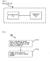
- Fig. 1 is a block diagram illustrating a base station 100 in accordance with the present invention.
- the base station 100 includes a selection section 110 and a transmission section 120.
- the base station 100 also includes other functional sections (e.g., various processors and memories) for carrying out a function thereof.
- the selection section 110 selects, from a downlink subframe candidate group, a downlink subframe usable for transmission of the uplink scheduling information.
- the downlink subframe candidate group includes: (1) a first downlink subframe corresponding to the uplink subframe in accordance with a predetermined scheduling timing and (2) one or more second downlink subframes each not corresponding to the uplink subframe in accordance with the predetermined scheduling timing.
- the predetermined scheduling timing can be, for example, a frequency division duplex (FDD) scheduling timing defined by 3GPP LTE Release 10, but is not limited to such a scheduling timing.
- FDD frequency division duplex
- the selection section 110 selects one downlink subframe usable for transmission of the uplink scheduling information from the one or more second downlink subframes in a case where the first downlink subframe is unusable for transmission of the uplink scheduling information.
- the downlink subframe which is unusable for transmission of the uplink scheduling information can be a downlink subframe used as a subframe of the multicast-broadcast single-frequency network (MBSFN).
- MBSFN multicast-broadcast single-frequency network
- the one or more second downlink subframes include at least one downlink subframe which (i) is not used as the subframe of the MBSFN and (ii) is usable for transmission of the uplink scheduling information.
- the transmission section 120 transmits the uplink scheduling information in the downlink subframe selected by the selection section 110.
- one or more downlink subframes of the downlink subframes 1, 2, 3, 6, 7, and 8 may each be set as the subframe of the MBSFN.
- none of the downlink subframes 0, 4, 5, and 9 is used as the subframe of the MBSFN.
- the downlink subframe 4 can be used to transmit uplink scheduling information for scheduling the uplink subframe 8.
- the downlink subframe 5 can be used to transmit uplink scheduling information for scheduling the uplink subframe 9.
- the downlink subframe 9 can be used to transmit uplink scheduling information for scheduling the uplink subframe 3 of a subsequent radio frame. Meanwhile, since one or more downlink subframes of the downlink subframes 0, 1, 2, 5, 6, and 7 may each be set as the subframe of the MBSFN, it may be impossible to schedule one or more uplink subframes of uplink subframes 0, 1, 2, 5, 6, and 7 at the FDD mode scheduling timing defined by 3GPP LTE Release 10. The following description discusses an operation of such an uplink subframe that may not be scheduled.
- the base station 100 sets a downlink subframe candidate group for each uplink subframe.
- the downlink subframe candidate group which is set for each uplink subframe can include the downlink subframes 4, 5, 6, 7, and 8 of a radio frame f-1 followed by the radio frame f.
- the uplink subframes 0, 1, and 2 of the radio frame f correspond to the respective downlink subframes 6, 7, and 8 of the radio frame f-1 followed by the radio frame f.
- the downlink subframes 4 and 5, neither of which is used as the subframe of the MBSFN as described earlier, can be used to transmit uplink scheduling information.
- a downlink subframe candidate group which corresponds to an uplink subframe (e.g., 0, 1, or 2) to be scheduled includes: (1) a first downlink subframe (e.g., 6, 7, or 8) corresponding to the uplink subframe (e.g., 0, 1, or 2) in accordance with the FDD scheduling timing defined by 3GPP LTE Release 10 and (2) one or more second downlink subframes (e.g., 4 or 5) each not corresponding to the uplink subframe (e.g., 0, 1, or 2) in accordance with the FDD scheduling timing defined by 3GPP LTE Release 10.
- a first downlink subframe e.g., 6, 7, or 8
- the uplink subframe e.g., 0, 1, or 2
- second downlink subframes e.g., 4 or 5
- the downlink subframe candidate group which is set for each uplink subframe can include (i) the downlink subframe 9 of the radio frame f-1 followed by the radio frame f and (ii) the downlink subframes 0, 1, 2, and 3 of the radio frame f.
- the uplink subframes 5, 6, and 7 of the radio frame f correspond to the respective downlink subframes 1, 2, and 3 of the radio frame f.
- a downlink subframe candidate group which corresponds to an uplink subframe (e.g., 5, 6, or 7) to be scheduled includes: (1) a first downlink subframe (e.g., 1, 2, or 3) corresponding to the uplink subframe (e.g., 5, 6, or 7) in accordance with the FDD scheduling timing defined by 3GPP LTE Release 10 and (2) one or more second downlink subframes (e.g., 0 or 9) each not corresponding to the uplink subframe (e.g., 5, 6, or 7) in accordance with the FDD scheduling timing defined by 3GPP LTE Release 10.
- a first downlink subframe e.g., 1, 2, or 3
- second downlink subframes e.g., 0 or 9
- i 1 , i 2 , and i 3 indicate the respective uplink subframes 0, 1, and 2 (the first group) of the radio frame f
- j 1 , j 2 , j 3 , j 4 , and j 5 indicate the respective downlink subframes 4, 5, 6, 7, and 8 of the radio frame f-1 followed by the radio frame f in the downlink subframe candidate group which corresponds to the uplink subframe 0, 1, or 2.
- i 1 , i 2 , and i 3 indicate the respective uplink subframes 5, 6, and 7 (the second group) of the radio frame f
- j 1 indicates the downlink subframe 9 of the radio frame f-1 followed by the radio frame f
- j 2 , j 3 , j 4 , and j 5 indicate the respective downlink subframes 0, 1, 2, and 3 of the radio frame f in the downlink subframe candidate group which corresponds to the uplink subframe 5, 6, or 7.
- An MBSFN setting for the downlink subframes is expressed by a binary bit. "0" indicates that a downlink subframe is not used as the subframe of the MBSFN, whereas "1" indicates that a downlink subframe is used as the subframe of the MBSFN.
- An MBSFN setting for the downlink subframes j 1 , j 2 , j 3 , j 4 , and j 5 is expressed as j 1 j 2 j 3 j 4 j 5 , which is a 5-bit value.
- Table 1 specifies a value k of a scheduling timing when j 1 j 2 j 3 j 4 j 5 has a given MBSFN setting.
- the value k indicates a correspondence relationship between a specific uplink subframe m (i 1 , i 2 , or i 3 ) and a specific downlink subframe m-k (i.e., the downlink subframe m-k is used to transmit uplink scheduling information for scheduling the uplink subframe m).
- a system that supports scheduling across carriers and is capable of carrying out scheduling across carriers in a case where there exist one or more non-NCT carriers may cause the base station to carry out a process for carrying out scheduling across carriers for one NCT carrier.
- the scheduling timing described earlier can be used in a case where (i) the scheduling across carriers is not supported by the system, (ii) there exists no conventional common carrier that is suitable for the system, or (iii) the scheduling across carriers cannot be carried out by a conventional common carrier in the system (e.g., a gap between a frequency of the conventional common carrier and a frequency of the NCT carrier is too wide).
- uplink scheduling information included in the NCT carrier is transmitted via a downlink control channel (PDCCH/ePDCCH) by another carrier.
- a downlink control channel (PDCCH/ePDCCH) by another carrier.
- j 1 , j 2 , j 3 , j 4 , and j 5 indicate the respective downlink subframes 4, 5, 6, 7, and 8 of the radio frame f-1 followed by the radio frame f.
- i 1 , i 2 , and i 3 indicate the respective uplink subframes 0, 1, and 2 of the radio frame f.
- j 1 indicates the downlink subframe 9 of the radio frame f-1 followed by the radio frame f
- j 2 , j 3 , j 4 , and j 5 indicate the respective downlink subframes 0, 1, 2, and 3 of the radio frame f
- i 1 , i 2 , and i 3 indicate the respective uplink subframes 5, 6, and 7 of the radio frame f.
- j 1 , j 2 , j 3 , j 4 , and j 5 indicate the respective downlink subframes 4, 5, 6, 7, and 8 of the radio frame f.
- i 1 , i 2 , and i 3 indicate the respective uplink subframes 0, 1, and 2 of a radio frame f+1 following the radio frame f.
- the base station can assign the uplink subframes 1 and 2 of the radio frame f+1 following the radio frame f to each of identical or different UEs by scheduling the downlink subframe 7 of the radio frame f.
- the UEs each read uplink scheduling information and then specify, in accordance with an instruction from the uplink scheduling information, whether or not to carry out uplink transmission in each of the uplink subframes 1 and 2 of the radio frame f+1 following the radio frame f.
- the uplink subframe m is desirably scheduled across carriers by use of the downlink subframe m-4 of another carrier.
- the base station can assign the uplink subframes 1 and 2 of the radio frame f to each of identical or different UEs by scheduling the downlink subframe 7 of the radio frame f-1 followed by the radio frame f.
- the UEs can each read uplink scheduling information and then specify, in accordance with an instruction from the uplink scheduling information, whether or not to carry out uplink transmission in each of the uplink subframes 1 and 2 of the radio frame f.
- j 1 indicates the downlink subframe 9 of the radio frame f-1 followed by the radio frame f
- j 2 , j 3 , j 4 , and j 5 indicate the respective downlink subframes 0, 1, 2, and 3 of the radio frame f
- i 1 , i 2 , and i 3 indicate the respective uplink subframes 5, 6, and 7 of the radio frame f.
- the base station can assign the uplink subframes 5 and 6 of the radio frame f to each of identical or different UEs by scheduling the downlink subframe 1 of the radio frame f.
- the UEs can each read uplink scheduling information and then specify, in accordance with an instruction from the uplink scheduling information, whether or not to carry out uplink transmission in each of the uplink subframes 5 and 6 of the radio frame f.
- the value k of the scheduling timing of each of the uplink subframes of the radio frame f+1 is identical to the value k of the scheduling timing of each of the uplink subframes of the radio frame f.
- the uplink subframe m is desirably scheduled across carriers by use of the downlink subframe m-4 of another carrier.
- Fig. 2 is a flow chart showing a method 200 in accordance with the present invention for transmitting uplink scheduling information.
- the method 200 is carried out by the base station 100 and includes the steps below.
- the selection section 110 selects, from a downlink subframe candidate group, a downlink subframe usable for transmission of the uplink scheduling information.
- the downlink subframe candidate group includes: (1) a first downlink subframe corresponding to the uplink subframe in accordance with a predetermined scheduling timing and (2) one or more second downlink subframes each not corresponding to the uplink subframe in accordance with the predetermined scheduling timing.
- the selection section 110 selects, from the one or more second downlink subframes, one downlink subframe usable for transmission of the uplink scheduling information in a case where the first downlink subframe is unusable for transmission of the uplink scheduling information.
- the downlink subframe which is unusable for transmission of the uplink scheduling information is a downlink subframe used as a subframe of a multicast-broadcast single-frequency network (MBSFN).
- MBSFN multicast-broadcast single-frequency network
- the one or more second downlink subframes preferably include at least one downlink subframe which (i) is not used as the subframe of the MBSFN and (ii) is usable for transmission of the uplink scheduling information.
- the predetermined scheduling timing is a frequency division duplex (FDD) scheduling timing defined by Long Term Evolution (LTE) Release 10 of 3rd Generation Partnership Project (3GPP).
- FDD frequency division duplex
- the transmission section 120 transmits the uplink scheduling information in the selected downlink subframe.
- the present invention allows scheduling of a corresponding uplink subframe even if part of downlink subframes (e.g., downlink subframes for the MBMS) are unusable for transmission of uplink scheduling information. Further, the present invention, in which an FDD scheduling timing defined by current standards is used as much as possible, has a least influence on the current standards.
Landscapes
- Engineering & Computer Science (AREA)
- Computer Networks & Wireless Communication (AREA)
- Signal Processing (AREA)
- Mobile Radio Communication Systems (AREA)
Abstract
Description
- The present invention relates to mobile communication, specifically to a method and a base station each for transmitting uplink scheduling information.
- According to a long term evolution (LTE) system of 3rd Generation Partnership Project (3GPP), a base station (also referred to as a NodeB or an evolved NodeB (eNB)) transmits uplink scheduling information (e.g., an uplink licensing UL grant) via a physical downlink control channel (PDCCH) or an enhanced physical downlink control channel (ePDCCH). Then, a user equipment (UE) reads the uplink scheduling information in the PDCCH or the ePDCCH and then transmits uplink data in an uplink subframe indicated by that uplink scheduling information. Note that the UE may be a user terminal, a user node, a mobile terminal, or a tablet PC.
- 3GPP LTE Release 10 defines a scheduling timing indicative of a correspondence relationship between (a) a downlink subframe for transmitting uplink scheduling information and (b) an uplink subframe to be scheduled in accordance with the uplink scheduling information.
- A prior art document "R1-125117, 3GPP TSG RAN WG1 Meeting #71, Qualcomm Inc." points out a problem that may occur in LTE Release 12 which will support a new carrier type (NCT). In the NCT, a multimedia broadcast multicast service (MBMS) is supported by a system as it is, and the MBMS inherits standard settings of LTE Release 12 or earlier. According to the standard settings of LTE Release 12 or earlier, time-division multiplexing is employed for (i) an MBMS radio resource and (ii) a PDCCH radio resource in a subframe of a multicast-broadcast single-frequency network (MBSFN).
- According to LTE Release 12, the system uses the ePDCCH instead of the PDCCH in a frequency domain in which only an NCT carrier (simply abbreviated to an "NCT") is used. However, in this case, employment of time-division multiplexing makes it impossible for the MBMS radio resource and the ePDCCH radio resource in the subframe of the MBSFN to coexist in a single NCT carrier. Thus, it is necessary to modify a scheduling timing of an uplink resource so that the standard settings of LTE Release 12 or earlier are applied, as they are, to the MBMS in which the NCT in a frequency division duplex (FDD) mode is used.
- This requires a new scheduling timing which allows (i) scheduling of a corresponding uplink subframe and (ii) a least influence on current standards even if part of downlink subframes (e.g., a downlink subframe for the MBMS) is unusable for transmission of uplink scheduling information.
- An object of the present invention is to solve at least part of the problems.
- In order to attain the object, the present invention provides, as a first embodiment, a method for transmitting uplink scheduling information, including the steps of: for an uplink subframe to be scheduled in accordance with the uplink scheduling information, selecting, from a downlink subframe candidate group, a downlink subframe usable for transmission of the uplink scheduling information, the downlink subframe candidate group including (1) a first downlink subframe corresponding to the uplink subframe in accordance with a predetermined scheduling timing and (2) one or more second downlink subframes each not corresponding to the uplink subframe in accordance with the predetermined scheduling timing; and transmitting the uplink scheduling information in the selected downlink subframe.
- The method in accordance with an embodiment of the present invention is configured such that one downlink subframe usable for transmission of the uplink scheduling information is selected from the one or more second downlink subframes in a case where the first downlink subframe is unusable for transmission of the uplink scheduling information.
- The method in accordance with an embodiment of the present invention is configured such that the downlink subframe which is unusable for transmission of the uplink scheduling information is a downlink subframe used as a subframe of a multicast-broadcast single-frequency network (MBSFN).
- The method in accordance with an embodiment of the present invention is preferably configured such that the one or more second downlink subframes include at least one downlink subframe which (i) is not used as the subframe of the MBSFN and (ii) is usable for transmission of the uplink scheduling information.
- The method in accordance with an embodiment of the present invention is configured such that the predetermined scheduling timing is a frequency division duplex (FDD) scheduling timing defined by Long Term Evolution (LTE) Release 10 of 3rd Generation Partnership Project (3GPP).
- The present invention provides, as a second embodiment, a base station for transmitting uplink scheduling information, including: a selection section for selecting, for an uplink subframe to be scheduled in accordance with the uplink scheduling information, from a downlink subframe candidate group, a downlink subframe usable for transmission of the uplink scheduling information, the downlink subframe candidate group including (1) a first downlink subframe corresponding to the uplink subframe in accordance with a predetermined scheduling timing and (2) one or more second downlink subframes each not corresponding to the uplink subframe in accordance with the predetermined scheduling timing; and a transmission section for transmitting the uplink scheduling information in the downlink subframe selected by the selection section.
- The base station in accordance with an embodiment of the present invention is configured such that the transmission section selects, from the one or more second downlink subframes, one downlink subframe usable for transmission of the uplink scheduling information in a case where the first downlink subframe is unusable for transmission of the uplink scheduling information.
- The base station in accordance with an embodiment of the present invention is configured such that the downlink subframe which is unusable for transmission of the uplink scheduling information is a downlink subframe used as a subframe of a multicast-broadcast single-frequency network (MBSFN).
- The base station in accordance with an embodiment of the present invention is preferably configured such that the one or more second downlink subframes include at least one downlink subframe which (i) is not used as the subframe of the MBSFN and (ii) is usable for transmission of the uplink scheduling information.
- The base station in accordance with an embodiment of the present invention is configured such that the predetermined scheduling timing is a frequency division duplex (FDD) scheduling timing defined by Long Term Evolution (LTE) Release 10 of 3rd Generation Partnership Project (3GPP).
- The present invention allows (i) scheduling of a corresponding uplink subframe and (ii) a least influence on current standards even if part of downlink subframes (e.g., a downlink subframe for the MBMS) are unusable for transmission of uplink scheduling information.
-
-
Fig. 1 is a block diagram illustrating a base station in accordance with the present invention. -
Fig. 2 is a flow chart showing a method in accordance with the present invention for transmitting uplink scheduling information. - The above features and additional features of the present invention will be made clearer by the detailed description below with reference to the drawings.
- A principle and implementation of the present invention will be made clearer by the description below of specific embodiments with reference to the drawings of the present invention. Note that the present invention is not limited to the specific embodiments below. Note also that a detailed description of a publicly-known technique that does not directly relate to the present invention is omitted for convenience of description so that the present invention will not be misunderstood.
- The following description specifically discusses embodiments in accordance with the present invention by taking, as an example of an operating environment, an LTE Release 12 mobile communication system and a mobile communication system of an evolved version of LTE Release 12 or later. Note, however, that the present invention is not limited to the embodiments below but is also applicable to other various wireless communication systems such as a future 5G cellular communication system.
- In accordance with an FDD mode scheduling timing defined by 3GPP LTE Release 10, uplink scheduling information for scheduling an n+4th uplink subframe is transmitted in an nth downlink subframe. In other words, the nth downlink subframe corresponds to the n+4th uplink subframe. According to an NCT in an FDD mode, the nth downlink subframe which is set for an MBMS, i.e., is used as a subframe of a multicast-broadcast single-frequency network (MBSFN) as described earlier is unusable for transmission of uplink scheduling information. In such a case, the n+4th uplink subframe cannot be scheduled, at the scheduling timing defined by 3GPP LTE Release 10, for transmitting uplink data.
- According to the NCT in the FDD mode, one or more downlink subframes of
downlink subframes 1, 2, 3, 6, 7, and 8 may each be set as the subframe of the MBSFN. In other words, none of downlink subframes 0, 4, 5, and 9 is used as the subframe of the MBSFN. Thus, according to the new carrier type (NCT) in the FDD mode, one of thedownlink subframes 1, 2, 3, 6, 7, and 8 which one is used as the subframe of the MBSFN is unusable for transmission of uplink scheduling information. In such a case, an uplink subframe corresponding to the one of the downlink subframes in accordance with the scheduling timing defined by 3GPP LTE Release 10 cannot be scheduled for transmitting uplink data. - The embodiments of the present invention are described by taking, as an example, the case of the MBMS in which the NCT in the FDD mode is used. Note, however, that a person skilled in the art would understand that a case where a downlink subframe is unusable for transmission of uplink scheduling information is not limited to the case of the MBMS. Further, a scene in which the present invention is employed is not limited to such a scene as described earlier.
-
Fig. 1 is a block diagram illustrating abase station 100 in accordance with the present invention. As illustrated inFig. 1 , thebase station 100 includes aselection section 110 and atransmission section 120. Note that a person skilled in the art would understand that thebase station 100 also includes other functional sections (e.g., various processors and memories) for carrying out a function thereof. - For an uplink subframe to be scheduled in accordance with uplink scheduling information, the
selection section 110 selects, from a downlink subframe candidate group, a downlink subframe usable for transmission of the uplink scheduling information. The downlink subframe candidate group includes: (1) a first downlink subframe corresponding to the uplink subframe in accordance with a predetermined scheduling timing and (2) one or more second downlink subframes each not corresponding to the uplink subframe in accordance with the predetermined scheduling timing. - Note here that the predetermined scheduling timing can be, for example, a frequency division duplex (FDD) scheduling timing defined by 3GPP LTE Release 10, but is not limited to such a scheduling timing.
- According to an embodiment of the present invention, the
selection section 110 selects one downlink subframe usable for transmission of the uplink scheduling information from the one or more second downlink subframes in a case where the first downlink subframe is unusable for transmission of the uplink scheduling information. - Note here that the downlink subframe which is unusable for transmission of the uplink scheduling information can be a downlink subframe used as a subframe of the multicast-broadcast single-frequency network (MBSFN).
- According to an embodiment of the present invention, the one or more second downlink subframes include at least one downlink subframe which (i) is not used as the subframe of the MBSFN and (ii) is usable for transmission of the uplink scheduling information.
- The
transmission section 120 transmits the uplink scheduling information in the downlink subframe selected by theselection section 110. - The following description discusses operations of sections of the
base station 100 with reference to specific examples. Note that a person skilled in the art would understand that the present invention is not limited to the specific examples described below. Note also that the object of the present invention is achieved in a case where the sections of thebase station 100 each operate in accordance with the principle of the present invention. - As described earlier, one or more downlink subframes of the
downlink subframes 1, 2, 3, 6, 7, and 8 may each be set as the subframe of the MBSFN. In other words, none of the downlink subframes 0, 4, 5, and 9 is used as the subframe of the MBSFN. This makes it always possible to schedule uplink subframes 3, 4, 8, and 9 in accordance with the FDD mode scheduling timing defined by 3GPP LTE Release 10. That is, the downlink subframe 0 can be used to transmit uplink scheduling information for scheduling the uplink subframe 4. The downlink subframe 4 can be used to transmit uplink scheduling information for scheduling the uplink subframe 8. The downlink subframe 5 can be used to transmit uplink scheduling information for scheduling the uplink subframe 9. The downlink subframe 9 can be used to transmit uplink scheduling information for scheduling the uplink subframe 3 of a subsequent radio frame. Meanwhile, since one or more downlink subframes of thedownlink subframes 0, 1, 2, 5, 6, and 7 may each be set as the subframe of the MBSFN, it may be impossible to schedule one or more uplink subframes ofuplink subframes 0, 1, 2, 5, 6, and 7 at the FDD mode scheduling timing defined by 3GPP LTE Release 10. The following description discusses an operation of such an uplink subframe that may not be scheduled. - According to an embodiment of the present invention, the base station 100 (e.g., the selection section 110) sets a downlink subframe candidate group for each uplink subframe. In the embodiment of the present invention, as a non-limiting example of the downlink subframe candidate group which is set for each uplink subframe, the downlink subframe candidate group which is set for each of the
uplink subframes 0, 1, and 2 of a radio frame f can include the downlink subframes 4, 5, 6, 7, and 8 of a radio frame f-1 followed by the radio frame f. According to the FDD mode scheduling timing defined by 3GPP LTE Release 10, theuplink subframes 0, 1, and 2 of the radio frame f correspond to the respective downlink subframes 6, 7, and 8 of the radio frame f-1 followed by the radio frame f. Note that the downlink subframes 4 and 5, neither of which is used as the subframe of the MBSFN as described earlier, can be used to transmit uplink scheduling information. In other words, a downlink subframe candidate group which corresponds to an uplink subframe (e.g., 0, 1, or 2) to be scheduled includes: (1) a first downlink subframe (e.g., 6, 7, or 8) corresponding to the uplink subframe (e.g., 0, 1, or 2) in accordance with the FDD scheduling timing defined by 3GPP LTE Release 10 and (2) one or more second downlink subframes (e.g., 4 or 5) each not corresponding to the uplink subframe (e.g., 0, 1, or 2) in accordance with the FDD scheduling timing defined by 3GPP LTE Release 10. - Further, as a non-limiting example of the downlink subframe candidate group which is set for each uplink subframe, the downlink subframe candidate group which is set for each of the uplink subframes 5, 6, and 7 of the radio frame f can include (i) the downlink subframe 9 of the radio frame f-1 followed by the radio frame f and (ii) the
downlink subframes 0, 1, 2, and 3 of the radio frame f. According to the FDD mode scheduling timing defined by 3GPP LTE Release 10, the uplink subframes 5, 6, and 7 of the radio frame f correspond to therespective downlink subframes 1, 2, and 3 of the radio frame f. Note that the downlink subframes 0 and 9, neither of which is used as the subframe of the MBSFN as described earlier, can be used to transmit uplink scheduling information. In other words, a downlink subframe candidate group which corresponds to an uplink subframe (e.g., 5, 6, or 7) to be scheduled includes: (1) a first downlink subframe (e.g., 1, 2, or 3) corresponding to the uplink subframe (e.g., 5, 6, or 7) in accordance with the FDD scheduling timing defined by 3GPP LTE Release 10 and (2) one or more second downlink subframes (e.g., 0 or 9) each not corresponding to the uplink subframe (e.g., 5, 6, or 7) in accordance with the FDD scheduling timing defined by 3GPP LTE Release 10. - For convenience, the following description discusses an embodiment of the present invention by assuming (i) respective timings of scheduling of the
uplink subframes 0, 1, and 2, which belong to a first group, and (ii) respective timings of scheduling of the uplink subframes 5, 6, and 7, which belong to a second group. However, as every person skilled in the art knows, the present invention is not limited to such grouping, which is merely taken as an example. - Assume that three uplink subframes in each of the first group and the second group are denoted as respective i1, i2, and i3, and five downlink subframes in a downlink subframe candidate group which corresponds to i1, i2, and i3 are denoted as respective j1, j2, j3, j4, and j5. In a case where i1, i2, and i3 indicate the
respective uplink subframes 0, 1, and 2 (the first group) of the radio frame f, j1, j2, j3, j4, and j5 indicate the respective downlink subframes 4, 5, 6, 7, and 8 of the radio frame f-1 followed by the radio frame f in the downlink subframe candidate group which corresponds to theuplink subframe 0, 1, or 2. In a case where i1, i2, and i3 indicate the respective uplink subframes 5, 6, and 7 (the second group) of the radio frame f, j1 indicates the downlink subframe 9 of the radio frame f-1 followed by the radio frame f, and j2, j3, j4, and j5 indicate therespective downlink subframes 0, 1, 2, and 3 of the radio frame f in the downlink subframe candidate group which corresponds to the uplink subframe 5, 6, or 7. - An MBSFN setting for the downlink subframes is expressed by a binary bit. "0" indicates that a downlink subframe is not used as the subframe of the MBSFN, whereas "1" indicates that a downlink subframe is used as the subframe of the MBSFN. An MBSFN setting for the downlink subframes j1, j2, j3, j4, and j5 is expressed as j1j2j3j4j5, which is a 5-bit value. For example, j1j2j3j4j5 = 00101 for the first group means that (i) none of the downlink subframes 4, 5, and 7 of the radio frame f-1 followed by the radio frame f is set as the subframe of the MBSFN and (ii) the downlink subframes 6 and 8 of the radio frame f-1 followed by the radio frame f are each set as the subframe of the MBSFN. Further, j1j2j3j4j5 = 00101 for the second group means that (i) none of the downlink subframe 9 of the radio frame f-1 followed by the radio frame f and the downlink subframes 0 and 2 of the radio frame f is set as the subframe of the MBSFN and (ii) the
downlink subframes 1 and 3 of the radio frame f are each set as the subframe of the MBSFN. - Since none of the downlink subframes 0, 4, 5, and 9 can be the subframe of the MBSFN, j1j2 = 00. Meanwhile, j3j4j5 always has eight different MBSFN settings. Table 1 below specifies a value k of a scheduling timing when j1j2j3j4j5 has a given MBSFN setting. The value k indicates a correspondence relationship between a specific uplink subframe m (i1, i2, or i3) and a specific downlink subframe m-k (i.e., the downlink subframe m-k is used to transmit uplink scheduling information for scheduling the uplink subframe m). Note that 3GPP LTE Release 10 defines the FDD scheduling timing where k = 4.
[Table 1]Table 1 Value k of MBSFN Scheduling Timing j1j2j3j4j5 i1 i2 i3 00000 4 4 4 00001 4 4 5 00010 4 5 4 00011 4 6 6 00100 5 4 4 00101 5 4 5 00110 6 6 4 00111 6 7 7 - A system that supports scheduling across carriers and is capable of carrying out scheduling across carriers in a case where there exist one or more non-NCT carriers (i.e., one or more conventional common carriers) may cause the base station to carry out a process for carrying out scheduling across carriers for one NCT carrier. Meanwhile, the scheduling timing described earlier can be used in a case where (i) the scheduling across carriers is not supported by the system, (ii) there exists no conventional common carrier that is suitable for the system, or (iii) the scheduling across carriers cannot be carried out by a conventional common carrier in the system (e.g., a gap between a frequency of the conventional common carrier and a frequency of the NCT carrier is too wide). In the scheduling across carriers, to which scheduling the frequency division duplex (FDD) scheduling timing defined by the current LTE Release 10 is conventionally applied, uplink scheduling information included in the NCT carrier is transmitted via a downlink control channel (PDCCH/ePDCCH) by another carrier. For example, in a case where a method for carrying out the scheduling across carriers is employed and a downlink subframe m-4 cannot be used to schedule an uplink subframe m of its own carrier, the uplink subframe m is scheduled across carriers by use of the downlink subframe m-4 of another carrier.
- The following description discusses specific examples with reference to Table 1. Note that the principle of the present invention is not limited to the specific examples below, which are merely schematic examples.
- As described earlier, it is always possible to schedule the uplink subframes 3, 4, 8, and 9 of any of the radio frames.
- Next, assume that j1, j2, j3, j4, and j5 indicate the respective downlink subframes 4, 5, 6, 7, and 8 of the radio frame f-1 followed by the radio frame f. In this case, i1, i2, and i3 indicate the
respective uplink subframes 0, 1, and 2 of the radio frame f. Since none of j1, j2, j3, j4, and j5 of the present embodiment is set as the subframe of the MBSFN, an MBSFN setting is expressed as j1j2j3j4j5 = 00000. As shown in Table 1, k, to which the uplink subframes each correspond, = 4. That is, uplink scheduling information can be transmitted in accordance with the FDD scheduling timing defined by 3GPP LTE Release 10. - Subsequently, assume that j1 indicates the downlink subframe 9 of the radio frame f-1 followed by the radio frame f, and j2, j3, j4, and j5 indicate the
respective downlink subframes 0, 1, 2, and 3 of the radio frame f. In this case, i1, i2, and i3 indicate the respective uplink subframes 5, 6, and 7 of the radio frame f. Further, the MBSFN setting in this case is expressed as j1j2j3j4j5 = 00110. As shown in Table 1, it is revealed: - (i) that k, to which the uplink subframe i1 corresponds, = 6, i.e., the uplink subframe 5 of the radio frame f corresponds to the downlink subframe 9 of the radio frame f-1 followed by the radio frame f;
- (ii) that k, to which the uplink subframe i2 corresponds, = 6, i.e., the uplink subframe 6 of the radio frame f corresponds to the downlink subframe 0 of the radio frame f; and
- (iii) that k, to which the uplink subframe i3 corresponds, = 4, i.e., the uplink subframe 7 of the radio frame f corresponds to the downlink subframe 3 of the radio frame f.
- Further, assume that j1, j2, j3, j4, and j5 indicate the respective downlink subframes 4, 5, 6, 7, and 8 of the radio frame f. In this case, i1, i2, and i3 indicate the
respective uplink subframes 0, 1, and 2 of a radio frame f+1 following the radio frame f. Further, the MBSFN setting in this case is expressed as j1j2j3j4j5 = 00001. As shown in Table 1, it is revealed: - (i) that k, to which the uplink subframe i1 corresponds, = 4, i.e., the uplink subframe 0 of the radio frame f+1 following the radio frame f corresponds to the downlink subframe 6 of the radio frame f;
- (ii) that k, to which the uplink subframe i2 corresponds, = 4, i.e., the
uplink subframe 1 of the radio frame f+1 following the radio frame f corresponds to the downlink subframe 7 of the radio frame f; and - (iii) that k, to which the uplink subframe i3 corresponds, = 5, i.e., the uplink subframe 2 of the radio frame f+1 following the radio frame f corresponds to the downlink subframe 7 of the radio frame f.
- Note that the base station can assign the
uplink subframes 1 and 2 of the radio frame f+1 following the radio frame f to each of identical or different UEs by scheduling the downlink subframe 7 of the radio frame f. The UEs each read uplink scheduling information and then specify, in accordance with an instruction from the uplink scheduling information, whether or not to carry out uplink transmission in each of theuplink subframes 1 and 2 of the radio frame f+1 following the radio frame f. - As described earlier, in a case where the method for carrying out the scheduling across carriers is employed and a downlink subframe m-4 cannot be used to schedule an uplink subframe m of its own carrier, the uplink subframe m is desirably scheduled across carriers by use of the downlink subframe m-4 of another carrier.
- As described earlier, it is always possible to schedule the uplink subframes 3, 4, 8, and 9 of any of the radio frames.
- Next, assume (i) that j1, j2, j3, j4, and j5 indicate the respective downlink subframes 4, 5, 6, 7, and 8 of the radio frame f-1 followed by the radio frame f and (ii) that i1, i2, and i3 indicate the
respective uplink subframes 0, 1, and 2 of the radio frame f. Further, the MBSFN setting in this case is expressed as j1j2j3j4j5 = 00101. As shown in Table 1, it is revealed: - (i) that k, to which the uplink subframe i1 corresponds, = 5, i.e., the uplink subframe 0 of the radio frame f corresponds to the downlink subframe 5 of the radio frame f-1 followed by the radio frame f;
- (ii) that k, to which the uplink subframe i2 corresponds, = 4, i.e., the
uplink subframe 1 of the radio frame f corresponds to the downlink subframe 7 of the radio frame f-1 followed by the radio frame f; and - (iii) that k, to which the uplink subframe i3 corresponds, = 5, i.e., the uplink subframe 2 of the radio frame f corresponds to the downlink subframe 7 of the radio frame f-1 followed by the radio frame f.
- Note that the base station can assign the
uplink subframes 1 and 2 of the radio frame f to each of identical or different UEs by scheduling the downlink subframe 7 of the radio frame f-1 followed by the radio frame f. The UEs can each read uplink scheduling information and then specify, in accordance with an instruction from the uplink scheduling information, whether or not to carry out uplink transmission in each of theuplink subframes 1 and 2 of the radio frame f. - Subsequently, assume that j1 indicates the downlink subframe 9 of the radio frame f-1 followed by the radio frame f, and j2, j3, j4, and j5 indicate the
respective downlink subframes 0, 1, 2, and 3 of the radio frame f. In this case, i1, i2, and i3 indicate the respective uplink subframes 5, 6, and 7 of the radio frame f. Further, the MBSFN setting in this case is expressed as j1j2j3j4j5 = 00010. As shown in Table 1, it is revealed: - (i) that k, to which the uplink subframe i1 corresponds, = 4, i.e., the uplink subframe 5 of the radio frame f corresponds to the
downlink subframe 1 of the radio frame f; - (ii) that k, to which the uplink subframe i2 corresponds, = 5, i.e., the uplink subframe 6 of the radio frame f corresponds to the
downlink subframe 1 of the radio frame f; and - (iii) that k, to which the uplink subframe i3 corresponds, = 4, i.e., the uplink subframe 7 of the radio frame f corresponds to the downlink subframe 3 of the radio frame f.
- Note that the base station can assign the uplink subframes 5 and 6 of the radio frame f to each of identical or different UEs by scheduling the
downlink subframe 1 of the radio frame f. The UEs can each read uplink scheduling information and then specify, in accordance with an instruction from the uplink scheduling information, whether or not to carry out uplink transmission in each of the uplink subframes 5 and 6 of the radio frame f. - According to the present embodiment, in which a single MBSFN setting is employed for all of the radio frames, the value k of the scheduling timing of each of the uplink subframes of the radio frame f+1 is identical to the value k of the scheduling timing of each of the uplink subframes of the radio frame f.
- As described earlier, in a case where the method for carrying out the scheduling across carriers is employed and a downlink subframe m-4 cannot be used to schedule an uplink subframe m of its own carrier, the uplink subframe m is desirably scheduled across carriers by use of the downlink subframe m-4 of another carrier.
- The following description discusses, with reference to the drawings, a flow chart showing a method of the present invention for transmitting uplink scheduling information. Note that the method of the present invention is described below with reference to a specific embodiment of the
base station 100 so as to be more easily understood. Note, however, that the method of the present invention is described with reference to the above specific functional sections of the base station merely so as to be schematically described. The method of the present invention which method is carried out by, for example, a computer program can be carried out assuming that a base station is provided in a form of an aggregate in which a section and a device do not need to be distinguished from each other unlike those illustrated inFig. 1 . Further, all the features described with reference to the embodiment of thebase station 100 are applicable to the following embodiment of the method. -
Fig. 2 is a flow chart showing amethod 200 in accordance with the present invention for transmitting uplink scheduling information. Themethod 200 is carried out by thebase station 100 and includes the steps below. - That is, in a step S210, for an uplink subframe to be scheduled in accordance with the uplink scheduling information, the
selection section 110 selects, from a downlink subframe candidate group, a downlink subframe usable for transmission of the uplink scheduling information. The downlink subframe candidate group includes: (1) a first downlink subframe corresponding to the uplink subframe in accordance with a predetermined scheduling timing and (2) one or more second downlink subframes each not corresponding to the uplink subframe in accordance with the predetermined scheduling timing. - In the step S210, the
selection section 110 selects, from the one or more second downlink subframes, one downlink subframe usable for transmission of the uplink scheduling information in a case where the first downlink subframe is unusable for transmission of the uplink scheduling information. - Specifically, the downlink subframe which is unusable for transmission of the uplink scheduling information is a downlink subframe used as a subframe of a multicast-broadcast single-frequency network (MBSFN).
- The one or more second downlink subframes preferably include at least one downlink subframe which (i) is not used as the subframe of the MBSFN and (ii) is usable for transmission of the uplink scheduling information.
- According to the embodiment of the present invention, the predetermined scheduling timing is a frequency division duplex (FDD) scheduling timing defined by Long Term Evolution (LTE) Release 10 of 3rd Generation Partnership Project (3GPP).
- In a step S220, the
transmission section 120 transmits the uplink scheduling information in the selected downlink subframe. - The present invention allows scheduling of a corresponding uplink subframe even if part of downlink subframes (e.g., downlink subframes for the MBMS) are unusable for transmission of uplink scheduling information. Further, the present invention, in which an FDD scheduling timing defined by current standards is used as much as possible, has a least influence on the current standards.
- The above description has discussed the present invention by illustrating favorable embodiments of the present invention. A person skilled in the art would understand that the present invention can be variously improved, replaced, or altered within the spirit and scope of the present invention. Accordingly, the present invention shall be limited by the scope of the claims of the present application and its equivalent without being limited to the embodiments above.
Claims (10)
- A method for transmitting uplink scheduling information, comprising the steps of:for an uplink subframe to be scheduled in accordance with the uplink scheduling information, selecting, from a downlink subframe candidate group, a downlink subframe usable for transmission of the uplink scheduling information, the downlink subframe candidate group including (1) a first downlink subframe corresponding to the uplink subframe in accordance with a predetermined scheduling timing and (2) one or more second downlink subframes each not corresponding to the uplink subframe in accordance with the predetermined scheduling timing; andtransmitting the uplink scheduling information in the selected downlink subframe.
- The method as set forth in claim 1, wherein one downlink subframe usable for transmission of the uplink scheduling information is selected from the one or more second downlink subframes in a case where the first downlink subframe is unusable for transmission of the uplink scheduling information.
- The method as set forth in claim 2, wherein the downlink subframe which is unusable for transmission of the uplink scheduling information is a downlink subframe used as a subframe of a multicast-broadcast single-frequency network (MBSFN).
- The method as set forth in any one of claims 1 through 3, wherein the one or more second downlink subframes include at least one downlink subframe which (i) is not used as the subframe of the MBSFN and (ii) is usable for transmission of the uplink scheduling information.
- The method as set forth in any one of claims 1 through 3, wherein the predetermined scheduling timing is a frequency division duplex (FDD) scheduling timing defined by Long Term Evolution (LTE) Release 10 of 3rd Generation Partnership Project (3GPP).
- A base station for transmitting uplink scheduling information, comprising:a selection section for selecting, for an uplink subframe to be scheduled in accordance with the uplink scheduling information, from a downlink subframe candidate group, a downlink subframe usable for transmission of the uplink scheduling information, the downlink subframe candidate group including (1) a first downlink subframe corresponding to the uplink subframe in accordance with a predetermined scheduling timing and (2) one or more second downlink subframes each not corresponding to the uplink subframe in accordance with the predetermined scheduling timing; anda transmission section for transmitting the uplink scheduling information in the downlink subframe selected by the selection section.
- The base station as set forth in claim 6, wherein the transmission section selects, from the one or more second downlink subframes, one downlink subframe usable for transmission of the uplink scheduling information in a case where the first downlink subframe is unusable for transmission of the uplink scheduling information.
- The base station as set forth in claim 7, wherein the downlink subframe which is unusable for transmission of the uplink scheduling information is a downlink subframe used as a subframe of a multicast-broadcast single-frequency network (MBSFN).
- The base station as set forth in any one of claims 6 through 8, wherein the one or more second downlink subframes include at least one downlink subframe which (i) is not used as the subframe of the MBSFN and (ii) is usable for transmission of the uplink scheduling information.
- The base station as set forth in any one of claims 6 through 8, wherein the predetermined scheduling timing is a frequency division duplex (FDD) scheduling timing defined by Long Term Evolution (LTE) Release 10 of 3rd Generation Partnership Project (3GPP).
Applications Claiming Priority (2)
| Application Number | Priority Date | Filing Date | Title |
|---|---|---|---|
| CN201210574807.7A CN103905997A (en) | 2012-12-26 | 2012-12-26 | Method for sending uplink scheduling information and base station |
| PCT/CN2013/090438 WO2014101771A1 (en) | 2012-12-26 | 2013-12-25 | Method for sending uplink scheduling information, and base station |
Publications (2)
| Publication Number | Publication Date |
|---|---|
| EP2941074A1 true EP2941074A1 (en) | 2015-11-04 |
| EP2941074A4 EP2941074A4 (en) | 2016-08-03 |
Family
ID=50997109
Family Applications (1)
| Application Number | Title | Priority Date | Filing Date |
|---|---|---|---|
| EP13869181.1A Withdrawn EP2941074A4 (en) | 2012-12-26 | 2013-12-25 | Method for sending uplink scheduling information, and base station |
Country Status (5)
| Country | Link |
|---|---|
| US (1) | US9629176B2 (en) |
| EP (1) | EP2941074A4 (en) |
| JP (1) | JP2016506171A (en) |
| CN (1) | CN103905997A (en) |
| WO (1) | WO2014101771A1 (en) |
Family Cites Families (12)
| Publication number | Priority date | Publication date | Assignee | Title |
|---|---|---|---|---|
| KR101539775B1 (en) * | 2009-01-08 | 2015-07-30 | 엘지전자 주식회사 | Data Relay Method in TDD-based Wireless Communication System |
| US8675579B2 (en) * | 2010-05-03 | 2014-03-18 | Futurewei Technologies, Inc. | System and method for allocating network resources for a communications link |
| CN102413515B (en) * | 2010-09-20 | 2015-06-03 | 中兴通讯股份有限公司 | Data transmission method and system thereof |
| CN102624507B (en) * | 2011-02-01 | 2015-04-08 | 华为技术有限公司 | Uplink/downlink scheduling information transmitting and receiving methods and device |
| WO2012106840A1 (en) * | 2011-02-10 | 2012-08-16 | Renesas Mobile Corporation | Resource allocation for flexible tdd configuration |
| CN104883243B (en) * | 2011-02-24 | 2018-06-05 | 华为技术有限公司 | For the communication means and device of carrier aggregation system |
| CN102752862B (en) * | 2011-04-20 | 2015-09-09 | 华为技术有限公司 | The method of up-downgoing data traffic transmission, base station and subscriber equipment |
| WO2012171465A1 (en) | 2011-06-14 | 2012-12-20 | 华为技术有限公司 | Communication method and device in time division duplex system |
| US9912439B2 (en) * | 2011-11-10 | 2018-03-06 | Qualcomm Incorporated | Method and apparatus for sending channel state information using subframe-dependent control channel formats |
| CN104067667A (en) * | 2012-01-23 | 2014-09-24 | 英特尔公司 | Network-assisted user association and offloading techniques for integrated multi-RAT heterogeneous networks |
| US9681382B2 (en) * | 2012-05-11 | 2017-06-13 | Intel Corporation | Radio coexistence in wireless networks |
| CA3067371C (en) * | 2012-09-26 | 2023-01-10 | Interdigital Patent Holdings, Inc. | Methods for dynamic tdd uplink/downlink configuration |
-
2012
- 2012-12-26 CN CN201210574807.7A patent/CN103905997A/en active Pending
-
2013
- 2013-12-25 JP JP2015549972A patent/JP2016506171A/en active Pending
- 2013-12-25 EP EP13869181.1A patent/EP2941074A4/en not_active Withdrawn
- 2013-12-25 US US14/655,629 patent/US9629176B2/en not_active Expired - Fee Related
- 2013-12-25 WO PCT/CN2013/090438 patent/WO2014101771A1/en not_active Ceased
Also Published As
| Publication number | Publication date |
|---|---|
| US9629176B2 (en) | 2017-04-18 |
| CN103905997A (en) | 2014-07-02 |
| US20150334738A1 (en) | 2015-11-19 |
| EP2941074A4 (en) | 2016-08-03 |
| WO2014101771A1 (en) | 2014-07-03 |
| JP2016506171A (en) | 2016-02-25 |
Similar Documents
| Publication | Publication Date | Title |
|---|---|---|
| CN108702740B (en) | Communication method and communication device | |
| JP7039469B2 (en) | Network support for distributed unscheduled transmission | |
| US10461975B2 (en) | Dynamic cyclic prefix (CP) length in wireless communication | |
| US9967861B2 (en) | Uplink resource scheduling method, wireless base station and mobile station | |
| JP2021007251A (en) | Methods and Devices for Using Short Transmission Time Intervals in Wireless Communications Networks | |
| JP6655766B2 (en) | Enabling multiple numerologies in a network | |
| CN107027184A (en) | A kind of downlink control information transmission method and device | |
| CN102202324A (en) | Method and system of resource position indication and channel blind detection, and apparatus thereof | |
| EP3411994A1 (en) | Search space design for machine-type communications | |
| JP2018511277A (en) | Communications system | |
| CN115088352B (en) | Semi-static scheduling of multicast broadcast service traffic | |
| US10588103B2 (en) | Synchronization for standalone LTE broadcast | |
| CN116058024B (en) | Methods and systems for managing configuration and control information for MBS services in wireless networks. | |
| CN113196853B (en) | Side chain resource allocation | |
| US12150115B2 (en) | Method performed by user equipment, and user equipment | |
| JP2014532350A (en) | Data transmission / reception method and apparatus in wireless communication system | |
| CN108111281A (en) | Data channel method for parameter configuration and device | |
| JP2016518740A (en) | User equipment grouping and common control signal transmission to user equipment groups | |
| AU2017237819A1 (en) | Communication of broadcast reference signal | |
| CN113099540A (en) | Method and apparatus for uplink channel multiplexing and waveform selection | |
| CN109075930B (en) | Method, device, and medium for search space configuration of MTC device | |
| WO2017133479A1 (en) | Method and apparatus for transmitting downlink control information | |
| JP5664786B2 (en) | Mobile communication system, radio base station, mobile station, data transmission method, data reception method, and program | |
| US9560671B2 (en) | Method and base station for transmitting scheduling information | |
| US9629176B2 (en) | Method and base station for transmitting uplink scheduling information |
Legal Events
| Date | Code | Title | Description |
|---|---|---|---|
| PUAI | Public reference made under article 153(3) epc to a published international application that has entered the european phase |
Free format text: ORIGINAL CODE: 0009012 |
|
| 17P | Request for examination filed |
Effective date: 20150702 |
|
| AK | Designated contracting states |
Kind code of ref document: A1 Designated state(s): AL AT BE BG CH CY CZ DE DK EE ES FI FR GB GR HR HU IE IS IT LI LT LU LV MC MK MT NL NO PL PT RO RS SE SI SK SM TR |
|
| AX | Request for extension of the european patent |
Extension state: BA ME |
|
| DAX | Request for extension of the european patent (deleted) | ||
| A4 | Supplementary search report drawn up and despatched |
Effective date: 20160701 |
|
| RIC1 | Information provided on ipc code assigned before grant |
Ipc: H04W 72/12 20090101ALI20160627BHEP Ipc: H04W 72/04 20090101AFI20160627BHEP |
|
| 17Q | First examination report despatched |
Effective date: 20170804 |
|
| STAA | Information on the status of an ep patent application or granted ep patent |
Free format text: STATUS: THE APPLICATION HAS BEEN WITHDRAWN |
|
| 18W | Application withdrawn |
Effective date: 20171102 |