EP2940871A1 - Frequency compensation - Google Patents
Frequency compensation Download PDFInfo
- Publication number
- EP2940871A1 EP2940871A1 EP15161622.4A EP15161622A EP2940871A1 EP 2940871 A1 EP2940871 A1 EP 2940871A1 EP 15161622 A EP15161622 A EP 15161622A EP 2940871 A1 EP2940871 A1 EP 2940871A1
- Authority
- EP
- European Patent Office
- Prior art keywords
- frequency
- temperature
- oscillator
- difference
- ideal component
- Prior art date
- Legal status (The legal status is an assumption and is not a legal conclusion. Google has not performed a legal analysis and makes no representation as to the accuracy of the status listed.)
- Granted
Links
Images



Classifications
-
- H—ELECTRICITY
- H03—ELECTRONIC CIRCUITRY
- H03L—AUTOMATIC CONTROL, STARTING, SYNCHRONISATION OR STABILISATION OF GENERATORS OF ELECTRONIC OSCILLATIONS OR PULSES
- H03L1/00—Stabilisation of generator output against variations of physical values, e.g. power supply
- H03L1/02—Stabilisation of generator output against variations of physical values, e.g. power supply against variations of temperature only
- H03L1/022—Stabilisation of generator output against variations of physical values, e.g. power supply against variations of temperature only by indirect stabilisation, i.e. by generating an electrical correction signal which is a function of the temperature
-
- H—ELECTRICITY
- H03—ELECTRONIC CIRCUITRY
- H03L—AUTOMATIC CONTROL, STARTING, SYNCHRONISATION OR STABILISATION OF GENERATORS OF ELECTRONIC OSCILLATIONS OR PULSES
- H03L1/00—Stabilisation of generator output against variations of physical values, e.g. power supply
- H03L1/02—Stabilisation of generator output against variations of physical values, e.g. power supply against variations of temperature only
- H03L1/028—Stabilisation of generator output against variations of physical values, e.g. power supply against variations of temperature only of generators comprising piezoelectric resonators
-
- H—ELECTRICITY
- H03—ELECTRONIC CIRCUITRY
- H03L—AUTOMATIC CONTROL, STARTING, SYNCHRONISATION OR STABILISATION OF GENERATORS OF ELECTRONIC OSCILLATIONS OR PULSES
- H03L7/00—Automatic control of frequency or phase; Synchronisation
- H03L7/24—Automatic control of frequency or phase; Synchronisation using a reference signal directly applied to the generator
Definitions
- the present application relates to determining environmental effects on an oscillator and in particular but not exclusively to determining the deviance of a generated frequency from an ideal due to temperature.
- GNSS global navigation satellite system
- a local signal is generated by a GNSS receiver in order to determine a phase difference with the satellite signal. This phase difference may then be used to determine the position of the receiver with respect to the satellite.
- the accuracy of the local signal is important to the functioning of the system. Any frequency error in the locally generated signal leads to an increase in the time taken to acquire the satellite signal as the receiver has to search not only for a phase difference but also potential frequency differences.
- Temperature of an oscillator has an effect on the accuracy of the oscillator.
- the frequency of the oscillator may vary with a change in temperature.
- many oscillator have built in temperature compensation, for example the temperature controlled crystal oscillator (TXCO) however such temperature compensation pushes up component price of an oscillator and may increase space required for the oscillator.
- TXCO temperature controlled crystal oscillator
- an apparatus comprising: a first oscillator configured to generate a first frequency; a second oscillator configured to generate a second frequency; and a processing means configured to: determine a difference between the first frequency and the second frequency; and determine a non-ideal component of the first frequency based on the difference between the first frequency and second frequency, where a relationship between the difference between the first and second frequencies and a non-ideal component of the first frequency is modelled; and wherein the determined non-ideal component of the first frequency may be used to compensate the first frequency.
- an apparatus comprising: a first oscillator configured to generate a first frequency; a second oscillator configured to generate a second frequency; and a processing means configured to: determine a difference between the first frequency and the second frequency; and determine a non-ideal component of the first frequency in dependence on a temperature response of the first and second oscillators.
- the temperature response of the first and second oscillator may correspond to a relationship of respective frequencies generated by the first and second oscillators with an operational temperature of the first and second oscillators.
- the temperature response may comprise a relationship between a difference between the first and second frequencies and the operational temperature of the first and second oscillators.
- the first and second oscillators may have respective temperature responses such that at any temperature in an operational temperature range of the apparatus, a difference between the first and second frequencies corresponds to a unique temperature.
- the first frequency may comprise an ideal component and the non-ideal component.
- the second frequency may comprise an ideal component and a non-ideal component.
- the apparatus of the first aspect may be provided as an integrated circuit die comprising:
- the integrated circuit die may be configured to compensate the first frequency in dependence on the determined non-ideal component of the first frequency and provide the compensated first frequency to further circuitry.
- the apparatus may be a global satellite navigation system receiver and may further comprise acquisition and tracking circuitry for a received navigation signal.
- a method comprising: generating a first frequency by a first oscillator; generating a second signal by a second oscillator; determining a difference between the first frequency and the second frequency; and determining a non-ideal component of the first frequency based on the difference between the first frequency and second frequency, where a relationship between the difference between the first and second frequencies and a non-ideal component of the first frequency is modelled; and wherein the determined non-ideal component of the first frequency may be used to compensate the first frequency.
- a method comprising: generating a first frequency by a first oscillator; generating a second signal by a second oscillator; determining a difference between the first frequency and the second frequency; and determining a non-ideal component of the first frequency in dependence on a temperature response of the first and second oscillators.
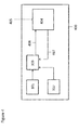
- Figure 1 shows an example of an apparatus in which embodiments of the present application may be implemented.
- Figure 1 comprises a first oscillator 101, a second oscillator 102 and a frequency controller 103. It will be appreciated that figure 1 is by way of example and the apparatus may comprise further functional circuitry.
- the apparatus may be a global navigation satellite system (GNSS) receiver such as a global positioning system (GPS) or Galileo receiver and may comprise further circuitry suitable for carrying out the functionality of such a receiver.
- GNSS global navigation satellite system
- GPS global positioning system
- Galileo receiver may comprise further circuitry suitable for carrying out the functionality of such a receiver.
- the apparatus of figure 1 may be any apparatus in which the accuracy of an oscillator is important.
- the first oscillator 101 may be configured to generate a first frequency and the second oscillator 102 may be configured to generate a second frequency.
- the first frequency may comprise an ideal component, namely the frequency the oscillator 101 is expected to or designed to generate.
- the first oscillator 101 may be a crystal oscillator configured to provide a frequency for the acquisition of a GNSS satellite system.
- the ideal component corresponds to the frequency that is required for the acquisition of the satellite signal.
- the ideal component may also be seen as the frequency generated by the oscillator under ideal conditions, for example ideal temperature conditions.
- the first frequency may also comprise a non-ideal component.
- the non-ideal component may be the contribution to the first frequency due to non-ideal conditions of the oscillator.
- the non-ideal component may be a component of the first frequency due to a non-ideal temperature response of the first oscillator 101.
- the non-ideal component may be considered to be the deviance of the first frequency from the ideal component of the first frequency.
- the first frequency may be compensated for the non-ideal component.
- One method of compensation is to provide the first oscillator 101 as a temperature controlled oscillator.
- the oscillator may have a built in temperature measurement and the first frequency may be compensated based on the temperature of the oscillator.
- such components tend to be expensive.
- Embodiments of the present application aim to compensate an oscillator frequency without having to include additional temperature measurement circuitry.
- Embodiments may determine a non-ideal component of a first frequency based on a temperature response of a first oscillator and a temperature response of a second oscillator.
- a relationship between a first and second frequency may indicate a non-ideal component of the first frequency based on a temperature response of the first oscillator.
- first frequency generated by the first oscillator 101 may comprise an ideal component and a non-ideal component.
- second frequency generated by the second oscillator 102 may comprise an ideal component and a non-ideal component.
- the first 101 and second 102 oscillators may have a known relationship between generated frequency and operational temperature of the oscillator.
- This relationship may for example be based on a mechanical structure of the oscillator, a frequency of the oscillator and/or measurements carried out on the oscillator, for example provided by a manufacturer of the oscillator.
- the relationship may for example describe a deviance of the oscillator frequency from a reference frequency according to temperature.
- This relationship may be the temperature response of the oscillator.
- the relationship may for example be indicative of a relationship between a deviance of a frequency (non-ideal component) to an ideal frequency (ideal component) of the oscillator. This relationship may be considered to be a frequency response of the oscillator.
- Figure 2 shows the temperature response of a first oscillator 201 and a second oscillator 202.
- the temperature response 201 of the first oscillator may be shown as the difference or deviance between and actual frequency (ideal and non-ideal components) generated by the oscillator and an ideal frequency (ideal component) of the oscillator.
- the temperature response 202 of the second oscillator may correspond to a difference between the second frequency and a reference signal, for example an ideal frequency of the first oscillator.
- the temperature response 202 of the second oscillator may be modelled as a difference between ideal components of the first and second oscillators plus a non-ideal component of the second oscillator.
- the temperature responses are by way of example only and in some embodiments the temperature response of an oscillator may correspond to a relationship between a non-ideal frequency component of the oscillator with a reference frequency.
- the first and second oscillators may have different characteristics which cause their temperature responses to differ.
- the apparatus may be a GNSS receiver and the first oscillator 101 may be used for the acquisition and tracking of a GNSS navigation signal.
- the second oscillator 102 may be for example a real time clock (RTC) oscillator for the apparatus 100.
- the oscillators may differ in frequency, for example the first oscillator 101 may generate a frequency of 26MHz whereas the second oscillator may generate a frequency of 32kHz.
- the first and second oscillator may additionally have different mechanical structure which may also cause their temperature responses to differ.
- the difference in the temperature response of the first oscillator 201 and the second oscillator 202 may be used to determine a non-ideal component of the first frequency 201. This determination may for example be carried out without the inclusion of temperature measurement circuitry.
- the non-ideal component of the first frequency may be determined based on a difference between the first frequency and the second frequency.
- the first and second frequencies comprise non-ideal components as well as ideal components.
- an operating temperature of the oscillators may be determined. This relationship between the difference between the first and second frequencies and temperature may be determined from 201 and 202. It will be appreciated that 201 and 202 may be based on prior measurements and/or characteristics of the oscillators, for example provided by the manufacturer.
- 201 models deviance (d 1 ) of the first frequency from the ideal as a function of temperature.
- 202 models the deviance of the second frequency from the ideal component of the first frequency (f 2 + d 2 - f 1 ) as a function of temperature.
- these form 203 which models the difference between the second frequency and the first frequency (f 2 - f 1 + d 2 - d 1 ).
- an operational temperature of the first 101 and second 102 oscillators may be determined based on a difference between the second frequency and the first frequency. From this determined temperature, the non-ideal component of the first frequency d 1 may be determined. The determined non-ideal component of the first frequency may be used to compensate the first frequency.
- the exact first and second frequencies being generated may not be known due to the unknown non-ideal components. However, a difference between the frequencies may be found and used to determine the deviance of the first frequency.
- Temperature may be determined based on a difference between the first and second frequencies when the temperature response 201 and 202 of the first 101 and second 102 oscillators differ such that a difference in the temperature responses corresponds to an unique temperature in an operating range of temperature, for example when the difference between the first and second frequencies is such that it corresponds to one temperature in an operating range of temperature for the oscillators.
- the operating range of temperature for the first and second oscillators may correspond to a range of temperatures in which the apparatus is expected to operate. This may for example differ with the functionality of the apparatus. For example if the apparatus is to be implemented in a non-terrestrial environment, an operational temperature range of the apparatus may differ to if it is to be implemented for domestic use.
- Figure 3 is a flow diagram showing an example of method steps that may be carried out in embodiments. In some embodiments, the method steps of figure 3 may be carried out by the frequency controller 103.
- a difference between a first frequency generated by a first oscillator 101 and a second frequency generated by a second oscillator 102 is determined.
- the difference may be determined for example by comparing the first frequency generated by the first oscillator and the second frequency generated by the second oscillator.
- the determined difference may be indicative of an operational temperature of the first and second oscillator.
- the determined difference may be used to determine an operational temperature of the first and second oscillator.
- the difference may be determined based on a relationship between the difference between the first and second frequencies and temperature.
- the relationship between the difference between the first and second frequencies and temperature may be modelled based on known characteristics of the oscillators.
- a temperature response for example a relationship between a frequency generated by the oscillator and temperature, may be known for each of the first and second oscillators and the relationship between the difference and temperature may be determined therefrom.
- a relationship between the difference between the first and second frequencies and a non-ideal frequency component of the first frequency may be modelled.
- step 302 is implicitly rather than explicitly carried out as the relationship between the difference between the first and second frequencies and a non-ideal frequency component of the first frequency is determined by the operational temperature of the oscillator.
- a non-ideal component of the first frequency may be determined based on the determined temperature. It will be appreciated that in some embodiments, the non-ideal component will be determined explicitly based on the determined temperature. In other embodiments, for example where a relationship between the difference between the first and second frequencies and a non-ideal frequency component of the first frequency is modelled, the determination of the non-ideal component may be based on the difference between the first frequency and the second frequency and dependent on temperature.
- steps of figure 3 refer to the difference between the first and second frequency, this may correspond to a difference between the frequencies as a whole or a difference between the non-ideal components of the first and second frequencies.
- these characteristics may include a relationship between a difference between the first and second frequency (or non-ideal components thereof) and temperature and a relationship between a non-ideal component of the first frequency and temperature.
- the characteristics may include a relationship between a difference between the first and second frequency (or non-ideal components thereof) and a non-ideal component of the first frequency. It will be appreciated that for both examples, these relationships may be based on the temperature response of the first and second oscillators. For example, the temperature response may be the non-ideal components of the first and second frequencies generated due to temperature.
- a determination of the operational temperature of the oscillators and the determination of the non-ideal frequency component of the first frequency may be made based on models corresponding to the temperature response of the first and second oscillator. These models may for example describe the relationships 201, 202 and 203 in figure 2 . It will also be appreciated that the models may describe relationships not shown in figure 2 but based thereon, for example the relationship between a difference between the first and second frequency and a non-ideal component of the first frequency.
- the frequency controller 103 may use the models and/or relationships to determine the non-ideal frequency component of the first frequency.
- the foregoing has described a first phase of operation in which the difference between the first and second frequencies us used to determine a non-ideal component and hence a compensation for the first frequency.
- some embodiments may further comprise a second phase of operation in which the compensated signal is compared to a reference signal and the resulting difference is used to update the model used to determine compensation. For example, an error between the compensated frequency and a frequency corresponding to the ideal component of the first frequency may be determined and used to update the model.
- the frequency controller 103 may be configured to update the models or relationships.
- the apparatus 100 may be a GNSS controller.
- Figure 4 shows an example of a GNSS controller 400 that may update the models used to determine the non-ideal component of the first frequency.
- Figure 4 shows an example of a GNSS receiver 400 including a first oscillator 101, a second oscillator 102 and a frequency controller 103.
- the frequency controller 103 may be implemented in software.
- the non-ideal component may be determined in software and at least part of the tracking and acquisition functionality of the receiver 100 may be carried out in software.
- Figure 4 further includes an acquisition and tracking block 404.
- the acquisition and tracking block 404 may receive a GNSS navigation signal at 405. It will be appreciated that this signal 405 may not be received directly from a transmitter such as a satellite, but may be first processed by other circuitry in or associated with the receiver 400. For example the signal 405 may be down-converted and/or pre-processed for noise.
- the frequency controller 103 may receive the first frequency from the first oscillator 101 and the second frequency from the second oscillator 102. The frequency controller 103 may use the first and second frequencies to determine a non-ideal component of the first frequency as described in relation to figures 2 and 3 using one or more models of the temperature response(s) of the first 101 and second 102 oscillators. The frequency controller 103 may further compensate the first frequency based on the determined non-ideal component.
- the frequency controller 103 may then provide the compensated frequency 406 to the tracking and acquisition block 404.
- the compensated frequency 406 may be used in the acquisition and tracking of the GNSS signal.
- the frequency controller 103 may update the models (for example the temperature response(s)) used to determine the non-ideal component of the first frequency.
- the frequency controller 103 may update the model(s) based on a frequency offset between the compensated first frequency 406 and an ideal first frequency.
- the first frequency comprises an ideal component and a non-ideal component.
- the frequency controller 103 may determine the non-ideal component of the first frequency and then compensate the first frequency for the non-ideal component in order to provide only the ideal component of the first frequency for example to the tracking and acquisition block. In other words, the frequency controller 103 compensates the first frequency to provide a frequency that the oscillator would generate under ideal conditions.
- the determination of the non-ideal component may not be entirely accurate. This may be for example due to other environmental or manufacturing effects that cause non-ideal behaviour of the oscillator other than temperature.
- the model giving the temperature response of the first and second oscillators may not be entirely accurate.
- the frequency controller 103 may therefore update or modify the model(s) in order to provide a more accurate model on which to base its determination. It may do this in response to an offset 407 between the compensated frequency and the ideal frequency of the oscillator (the frequency the oscillator would generate under ideal conditions).
- the first oscillator in a first phase of operation, is configured to generate a frequency of a navigation signal 405 received by the GNSS receiver 400. It will be appreciated that due to non-ideal conditions, the first frequency will not match the received navigation signal 405 exactly however the frequency controller may determine an non-ideal component and compensate the first frequency in order to provide a frequency to the tracking and acquisition block that is as close to the frequency of the received signal as it possibly can. The more accurate the compensated frequency, the quicker the received signal 405 may be acquired.
- the tracking and acquisition block 404 may provide an indication of an offset between the compensated frequency and the frequency of the received signal 405.
- This offset may be indicative of a difference between the frequency of the compensated signal and the frequency of the received signal 405.
- the frequency controller 103 may update its model(s) to more accurately determine the non-ideal component of the first frequency.
- the frequency of the received signal 405 may be considered to correspond to the ideal component of the first frequency.
- the determined non-ideal component of the first frequency may not be entirely accurate and an offset 407 between the ideal component (frequency of the received signal 405) and the compensated frequency 406 may indicate a difference between the determined non-ideal component and actual non-ideal component.
- the model(s) may correspond to a function, for example a polynomial but not restricted to such, that corresponds to the behaviour of the first and second oscillators under different temperature conditions (for example a temperature response).
- a function for example a polynomial but not restricted to such, that corresponds to the behaviour of the first and second oscillators under different temperature conditions (for example a temperature response).
- Each of the one or more function(s) may be described by a set of coefficients and these coefficients may be updated based on the offset 407.
- the one or more function(s) may for example be implemented in the form of a filter.
- the filter may comprise two aspects.
- a first aspect may relate to the temperature response of the first and second oscillator.
- the filter is used to determine a non-ideal frequency component based on a difference between the first and second frequencies. This determination may be used to apply compensation to the first frequency.
- the second mode or aspect of the filter is configured to update coefficients of the filter.
- An offset 407 may be determined by comparing the compensated frequency with the received frequency. The offset 407 may be used to update the filter coefficients.
- Figure 5 shows an example of the method steps that may be carried out to update the model in accordance with some embodiments.
- the frequency controller 103 may have an initial model for frequency compensation (for example 203 or a combined model of 201 and 203). It will be appreciated that his initial model may be generated by a theoretical approximation of the temperature response of the first and second oscillators.
- an offset between the compensated frequency and the received frequency for example a frequency of the GNSS signal, may be determined.
- the model may be updated to take into account these new data points.
- step 503 the method may loop back to step 502 where more measurements may be performed. It will be appreciated that these measurements may be performed periodically or at certain times specific to the receiver 400.
- the offset 407 at the determined temperature of the first and second oscillator forms a data point and is recorded.
- One or more data points may be used to update the model.
- a data point may be recorded about every 1 minute but it could be on any time scale dependent on the system implemented.
- a balance is to have a time period allowing for the temperature to change while still capturing data (the offset 407) at key temperature points.
- the time period may be a range from 10 second to 1 minute.
- One way of using data points to update the amount of compensation applied to a frequency is to store the data points in a table and reference them.
- the data points giving an error in the non-ideal component determination may be used to adjust the determination of the model by looking up an adjustment value in the table.
- the use of such a table is potentially inaccurate and may take up extra space in memory as well as additional computational steps.
- the model may be implemented by a real-time, recursive algorithm in which data points are input to the model and cause the model coefficients to be updated. In this case, no table of data points need be stored. In such algorithms the data points may be filtered, resulting in an update of the coefficients of the filter.
- Such an algorithm may be for example a linear quadratic estimation algorithm or a Kalman filter.
- the Kalman filter or linear quadratic estimation may be used to provide a model defined by coefficients.
- the coefficients of the model may describe the behaviour of an oscillator frequency with regards to the temperature of the oscillator.
- the coefficients may describe a not entirely accurate approximation of the behaviour.
- the Kalman filter may provide an algorithm that accepts a series of data points comprising the determined temperature and offset and use these data points to provide more accurate estimations of the coefficients.
- the Kalman filter of embodiments may operate recursively and process each data point as it is generated. In other words, in some embodiment, the data points need not be stored in a table, but may be processed by the Kalman filter to update the coefficients as the data points are generated.
- the Kalman filter may operate recursively.
- the initial model may in some embodiments, be the models 203 and 201. In other embodiments the model may be a combined model of 201 and 203.
- the temperature response may be given by the frequency difference of the frequency in parts per million (ppm) vs. temperature.
- the ideal component of the first frequency may be used as the reference for the ppm.
- the temperature response of the first oscillator may be the non-deal component of the first frequency in ppm of the ideal component of the first frequency.
- the temperature response of the second oscillator may be the difference between the second frequency and an ideal component of the first frequency in ppm of the ideal component of the first frequency.
- the combined response 203 may for example be the difference between the second and first frequencies in ppm of the ideal component of the first frequency.
- the ideal component of the first frequency may not be available (for example the navigation signal 405 may not have been acquired) when measuring the difference between the first frequency and the second frequency.
- the non-ideal component of the first frequency may be disregarded in the conversion to ppm and this difference may be given in ppm of the first frequency.
- the model 203 may be updated in the second phase to take into account any error incurred due to the non-ideal component of the first frequency in the ppm calculation.
- the first oscillator may not be configured to generate a first frequency that matches the frequency of the GNSS signal but rather be configured to generate a frequency that is a factor thereof.
- the oscillator hardware may be configured to scale this generated frequency to correspond to the frequency of the received signal. It will be appreciated that in some embodiments, the oscillator may generate the frequency of the received signal without any scaling.
- the apparatus 100 and/or 400 may be implemented as part of an integrated circuit die.
- the apparatus may form part of a single integrated package.
- the circuitry of the apparatus 100 may be provided as a single integrated circuit die and may output a compensated first frequency to further circuitry and or integrated die that may make use of the first frequency.
- the apparatus 100 may be provided as an oscillator that provides temperature compensation, for example in the place of a temperature controlled crystal oscillator (TXCO).
- TXCO temperature controlled crystal oscillator
- a frequency of the first and the second oscillators has been given as 26MHz and 32kHz respectively, however it will be appreciated that this is by way of example only and the oscillators may be configured to generate different frequencies.
- the temperature responses of the first and second oscillators may differ due to mechanical structure and frequency, however it will be appreciated that oscillators that have differing temperature responses due to other reasons may be implemented. Any oscillators may be implemented with temperature responses that differ sufficiently such that an operational temperature of the oscillators may be determined from a difference between the frequencies (or non-ideal components of the frequencies) generated by the oscillators. For example this may be due to a difference between the frequencies corresponding to an unique temperature due to the difference in the temperature responses of the oscillators.
- An appropriately adapted computer program code product or products may be used for implementing the embodiments, when loaded on an appropriate data processing apparatus, for example for compensating the frequency for error.
- the program code product for providing the operation may be stored on, provided and embodied by means of an appropriate carrier medium.
- An appropriate computer program can be embodied on a computer readable record medium. A possibility is to download the program code product via a data network.
- the various embodiments may be implemented in hardware or special purpose circuits, software, logic or any combination thereof. Embodiments of the inventions may thus be practiced in various components such as integrated circuit modules.
- the design of integrated circuits is by and large a highly automated process. Complex and powerful software tools are available for converting a logic level design into a semiconductor circuit design ready to be etched and formed on a semiconductor substrate.
Landscapes
- Stabilization Of Oscillater, Synchronisation, Frequency Synthesizers (AREA)
Abstract
Description
- The present application relates to determining environmental effects on an oscillator and in particular but not exclusively to determining the deviance of a generated frequency from an ideal due to temperature.
- Many systems make use of oscillators in order to provide a frequency. In some systems the accuracy of the frequency is important for the correct functioning of the system. One such system is a global navigation satellite system (GNSS).
- In order to acquire a received satellite signal, a local signal is generated by a GNSS receiver in order to determine a phase difference with the satellite signal. This phase difference may then be used to determine the position of the receiver with respect to the satellite.
- The accuracy of the local signal is important to the functioning of the system. Any frequency error in the locally generated signal leads to an increase in the time taken to acquire the satellite signal as the receiver has to search not only for a phase difference but also potential frequency differences.
- Temperature of an oscillator has an effect on the accuracy of the oscillator. The frequency of the oscillator may vary with a change in temperature. In order to address this, many oscillator have built in temperature compensation, for example the temperature controlled crystal oscillator (TXCO) however such temperature compensation pushes up component price of an oscillator and may increase space required for the oscillator.
- According to a first aspect, there is provided an apparatus comprising: a first oscillator configured to generate a first frequency; a second oscillator configured to generate a second frequency; and a processing means configured to: determine a difference between the first frequency and the second frequency; and determine a non-ideal component of the first frequency based on the difference between the first frequency and second frequency, where a relationship between the difference between the first and second frequencies and a non-ideal component of the first frequency is modelled; and wherein the determined non-ideal component of the first frequency may be used to compensate the first frequency.
- According to another aspect, there is provided an apparatus comprising: a first oscillator configured to generate a first frequency; a second oscillator configured to generate a second frequency; and a processing means configured to: determine a difference between the first frequency and the second frequency; and determine a non-ideal component of the first frequency in dependence on a temperature response of the first and second oscillators.
- The temperature response of the first and second oscillator may correspond to a relationship of respective frequencies generated by the first and second oscillators with an operational temperature of the first and second oscillators. The temperature response may comprise a relationship between a difference between the first and second frequencies and the operational temperature of the first and second oscillators.
- The first and second oscillators may have respective temperature responses such that at any temperature in an operational temperature range of the apparatus, a difference between the first and second frequencies corresponds to a unique temperature.
- The first frequency may comprise an ideal component and the non-ideal component. The second frequency may comprise an ideal component and a non-ideal component.
- According to another aspect, the apparatus of the first aspect may be provided as an integrated circuit die comprising:
- The integrated circuit die may be configured to compensate the first frequency in dependence on the determined non-ideal component of the first frequency and provide the compensated first frequency to further circuitry.
- According to another aspect, the apparatus may be a global satellite navigation system receiver and may further comprise acquisition and tracking circuitry for a received navigation signal.
- According to another aspect there is provided a method comprising: generating a first frequency by a first oscillator; generating a second signal by a second oscillator; determining a difference between the first frequency and the second frequency; and determining a non-ideal component of the first frequency based on the difference between the first frequency and second frequency, where a relationship between the difference between the first and second frequencies and a non-ideal component of the first frequency is modelled; and wherein the determined non-ideal component of the first frequency may be used to compensate the first frequency.
- According to another aspect, there is provided a method comprising: generating a first frequency by a first oscillator; generating a second signal by a second oscillator; determining a difference between the first frequency and the second frequency; and determining a non-ideal component of the first frequency in dependence on a temperature response of the first and second oscillators.
- The application will now be described with reference to the following figures in which:
-
Figure 1 shows an apparatus in accordance with some embodiments; -
Figure 2 shows an example of a temperature response of an oscillator; -
Figure 3 is a flow diagram depicting the method steps that may be carried in some embodiments; -
Figure 4 is an example of a receiver in which embodiments may be implemented; and -
Figure 5 is a flow diagram depicting the method steps carrying out some embodiments. -
Figure 1 shows an example of an apparatus in which embodiments of the present application may be implemented.Figure 1 comprises afirst oscillator 101, asecond oscillator 102 and afrequency controller 103. It will be appreciated thatfigure 1 is by way of example and the apparatus may comprise further functional circuitry. - In one example, the apparatus may be a global navigation satellite system (GNSS) receiver such as a global positioning system (GPS) or Galileo receiver and may comprise further circuitry suitable for carrying out the functionality of such a receiver. However it will be appreciated that the apparatus of
figure 1 may be any apparatus in which the accuracy of an oscillator is important. - It will be appreciated that the
first oscillator 101 may be configured to generate a first frequency and thesecond oscillator 102 may be configured to generate a second frequency. The first frequency may comprise an ideal component, namely the frequency theoscillator 101 is expected to or designed to generate. For example thefirst oscillator 101 may be a crystal oscillator configured to provide a frequency for the acquisition of a GNSS satellite system. In this example the ideal component corresponds to the frequency that is required for the acquisition of the satellite signal. The ideal component may also be seen as the frequency generated by the oscillator under ideal conditions, for example ideal temperature conditions. - The first frequency may also comprise a non-ideal component. The non-ideal component may be the contribution to the first frequency due to non-ideal conditions of the oscillator. For example the non-ideal component may be a component of the first frequency due to a non-ideal temperature response of the
first oscillator 101. The non-ideal component may be considered to be the deviance of the first frequency from the ideal component of the first frequency. - In systems where an accurate frequency is required, the first frequency may be compensated for the non-ideal component. One method of compensation is to provide the
first oscillator 101 as a temperature controlled oscillator. In this example, the oscillator may have a built in temperature measurement and the first frequency may be compensated based on the temperature of the oscillator. However, such components tend to be expensive. - Embodiments of the present application aim to compensate an oscillator frequency without having to include additional temperature measurement circuitry. Embodiments may determine a non-ideal component of a first frequency based on a temperature response of a first oscillator and a temperature response of a second oscillator. In some embodiments, a relationship between a first and second frequency may indicate a non-ideal component of the first frequency based on a temperature response of the first oscillator.
- It will be appreciated that the first frequency generated by the
first oscillator 101 may comprise an ideal component and a non-ideal component. Similarly the second frequency generated by thesecond oscillator 102 may comprise an ideal component and a non-ideal component. - Referring to
figure 1 , the first 101 and second 102 oscillators may have a known relationship between generated frequency and operational temperature of the oscillator. This relationship may for example be based on a mechanical structure of the oscillator, a frequency of the oscillator and/or measurements carried out on the oscillator, for example provided by a manufacturer of the oscillator. The relationship may for example describe a deviance of the oscillator frequency from a reference frequency according to temperature. This relationship may be the temperature response of the oscillator. The relationship may for example be indicative of a relationship between a deviance of a frequency (non-ideal component) to an ideal frequency (ideal component) of the oscillator. This relationship may be considered to be a frequency response of the oscillator. -
Figure 2 shows the temperature response of afirst oscillator 201 and asecond oscillator 202. Thetemperature response 201 of the first oscillator may be shown as the difference or deviance between and actual frequency (ideal and non-ideal components) generated by the oscillator and an ideal frequency (ideal component) of the oscillator. Thetemperature response 202 of the second oscillator may correspond to a difference between the second frequency and a reference signal, for example an ideal frequency of the first oscillator. Thus thetemperature response 202 of the second oscillator may be modelled as a difference between ideal components of the first and second oscillators plus a non-ideal component of the second oscillator. - It will be appreciated that the temperature responses are by way of example only and in some embodiments the temperature response of an oscillator may correspond to a relationship between a non-ideal frequency component of the oscillator with a reference frequency.
- The first and second oscillators may have different characteristics which cause their temperature responses to differ.
- In this example, the apparatus may be a GNSS receiver and the
first oscillator 101 may be used for the acquisition and tracking of a GNSS navigation signal. Thesecond oscillator 102 may be for example a real time clock (RTC) oscillator for theapparatus 100. The oscillators may differ in frequency, for example thefirst oscillator 101 may generate a frequency of 26MHz whereas the second oscillator may generate a frequency of 32kHz. The first and second oscillator may additionally have different mechanical structure which may also cause their temperature responses to differ. - The difference in the temperature response of the
first oscillator 201 and thesecond oscillator 202 may be used to determine a non-ideal component of thefirst frequency 201. This determination may for example be carried out without the inclusion of temperature measurement circuitry. The non-ideal component of the first frequency may be determined based on a difference between the first frequency and the second frequency. - For example a difference between the first frequency and the second frequency may be shown as follows:

where
fosc1 and fosc2 are the first and second frequencies generated by thefirst oscillator 101 and the second 102 oscillator respectively;
f1and f2 are the ideal components of the first and second frequencies respectively; and
d1 and d2 are the non-ideal components or deviance of the first and second frequencies respectively. - Referring the graph of
figure 2 it will be appreciated that the relationship between the non-ideal component (d1) of the first frequency (fosc1) and temperature is shown 201 and the relationship between the non-ideal component (d2) of the second frequency (fosc2) and temperature is known 202. Thus a relationship between the difference between the first and second frequencies (and non-ideal components thereof) and temperature is known and shown at 203. - In operation, the first and second frequencies comprise non-ideal components as well as ideal components. By modelling a difference between the first and second frequencies against temperature, an operating temperature of the oscillators may be determined. This relationship between the difference between the first and second frequencies and temperature may be determined from 201 and 202. It will be appreciated that 201 and 202 may be based on prior measurements and/or characteristics of the oscillators, for example provided by the manufacturer.
- For example, 201 models deviance (d1) of the first frequency from the ideal as a function of temperature. 202 models the deviance of the second frequency from the ideal component of the first frequency (f2 + d2 - f1) as a function of temperature. In combination, these
form 203 which models the difference between the second frequency and the first frequency (f2 - f1 + d2 - d1). - From 203, an operational temperature of the first 101 and second 102 oscillators may be determined based on a difference between the second frequency and the first frequency. From this determined temperature, the non-ideal component of the first frequency d1 may be determined. The determined non-ideal component of the first frequency may be used to compensate the first frequency.
- It will be appreciated, that in operation of the oscillators, the exact first and second frequencies being generated may not be known due to the unknown non-ideal components. However, a difference between the frequencies may be found and used to determine the deviance of the first frequency.
- It will appreciated that the temperature responses of 201 and 202 are by way of example only. In this example the
relationships temperature response - It will be appreciated that the operating range of temperature for the first and second oscillators may correspond to a range of temperatures in which the apparatus is expected to operate. This may for example differ with the functionality of the apparatus. For example if the apparatus is to be implemented in a non-terrestrial environment, an operational temperature range of the apparatus may differ to if it is to be implemented for domestic use.
-
Figure 3 is a flow diagram showing an example of method steps that may be carried out in embodiments. In some embodiments, the method steps offigure 3 may be carried out by thefrequency controller 103. - At
step 301 infigure 3 a difference between a first frequency generated by afirst oscillator 101 and a second frequency generated by asecond oscillator 102 is determined. The difference may be determined for example by comparing the first frequency generated by the first oscillator and the second frequency generated by the second oscillator. The determined difference may be indicative of an operational temperature of the first and second oscillator. - At
step 302, the determined difference may be used to determine an operational temperature of the first and second oscillator. The difference may be determined based on a relationship between the difference between the first and second frequencies and temperature. - In some examples the relationship between the difference between the first and second frequencies and temperature may be modelled based on known characteristics of the oscillators. In other or additional embodiments, a temperature response, for example a relationship between a frequency generated by the oscillator and temperature, may be known for each of the first and second oscillators and the relationship between the difference and temperature may be determined therefrom.
- In other or additional embodiments a relationship between the difference between the first and second frequencies and a non-ideal frequency component of the first frequency may be modelled. In this case,
step 302 is implicitly rather than explicitly carried out as the relationship between the difference between the first and second frequencies and a non-ideal frequency component of the first frequency is determined by the operational temperature of the oscillator. - At step 303 a non-ideal component of the first frequency may be determined based on the determined temperature. It will be appreciated that in some embodiments, the non-ideal component will be determined explicitly based on the determined temperature. In other embodiments, for example where a relationship between the difference between the first and second frequencies and a non-ideal frequency component of the first frequency is modelled, the determination of the non-ideal component may be based on the difference between the first frequency and the second frequency and dependent on temperature.
- It will be appreciated that while the steps of
figure 3 refer to the difference between the first and second frequency, this may correspond to a difference between the frequencies as a whole or a difference between the non-ideal components of the first and second frequencies. - It will be appreciated that the foregoing has described making determinations on the basis of characteristics of the first 101 and second 102 oscillator. In a first example these characteristics may include a relationship between a difference between the first and second frequency (or non-ideal components thereof) and temperature and a relationship between a non-ideal component of the first frequency and temperature. In a second example, the characteristics may include a relationship between a difference between the first and second frequency (or non-ideal components thereof) and a non-ideal component of the first frequency. It will be appreciated that for both examples, these relationships may be based on the temperature response of the first and second oscillators. For example, the temperature response may be the non-ideal components of the first and second frequencies generated due to temperature.
- In some embodiments, a determination of the operational temperature of the oscillators and the determination of the non-ideal frequency component of the first frequency may be made based on models corresponding to the temperature response of the first and second oscillator. These models may for example describe the
relationships figure 2 . It will also be appreciated that the models may describe relationships not shown infigure 2 but based thereon, for example the relationship between a difference between the first and second frequency and a non-ideal component of the first frequency. - In embodiments, the
frequency controller 103 may use the models and/or relationships to determine the non-ideal frequency component of the first frequency.
The foregoing has described a first phase of operation in which the difference between the first and second frequencies us used to determine a non-ideal component and hence a compensation for the first frequency. It will be appreciated, that some embodiments may further comprise a second phase of operation in which the compensated signal is compared to a reference signal and the resulting difference is used to update the model used to determine compensation. For example, an error between the compensated frequency and a frequency corresponding to the ideal component of the first frequency may be determined and used to update the model. It will also be appreciated that in some embodiments, thefrequency controller 103 may be configured to update the models or relationships. - In this example, the
apparatus 100 may be a GNSS controller.Figure 4 shows an example of aGNSS controller 400 that may update the models used to determine the non-ideal component of the first frequency. -
Figure 4 shows an example of aGNSS receiver 400 including afirst oscillator 101, asecond oscillator 102 and afrequency controller 103. It will be appreciated that in some embodiments, thefrequency controller 103 may be implemented in software. For example, the non-ideal component may be determined in software and at least part of the tracking and acquisition functionality of thereceiver 100 may be carried out in software. -
Figure 4 further includes an acquisition and trackingblock 404. The acquisition and trackingblock 404 may receive a GNSS navigation signal at 405. It will be appreciated that thissignal 405 may not be received directly from a transmitter such as a satellite, but may be first processed by other circuitry in or associated with thereceiver 400. For example thesignal 405 may be down-converted and/or pre-processed for noise. - The
frequency controller 103 may receive the first frequency from thefirst oscillator 101 and the second frequency from thesecond oscillator 102. Thefrequency controller 103 may use the first and second frequencies to determine a non-ideal component of the first frequency as described in relation tofigures 2 and3 using one or more models of the temperature response(s) of the first 101 and second 102 oscillators. Thefrequency controller 103 may further compensate the first frequency based on the determined non-ideal component. - The
frequency controller 103 may then provide the compensatedfrequency 406 to the tracking andacquisition block 404. The compensatedfrequency 406 may be used in the acquisition and tracking of the GNSS signal. - In addition to compensating the first frequency for the non-ideal component caused by temperature, the
frequency controller 103 in some embodiments, may update the models (for example the temperature response(s)) used to determine the non-ideal component of the first frequency. In this embodiment, thefrequency controller 103 may update the model(s) based on a frequency offset between the compensatedfirst frequency 406 and an ideal first frequency. - It will be appreciated that the first frequency comprises an ideal component and a non-ideal component. The
frequency controller 103 may determine the non-ideal component of the first frequency and then compensate the first frequency for the non-ideal component in order to provide only the ideal component of the first frequency for example to the tracking and acquisition block. In other words, thefrequency controller 103 compensates the first frequency to provide a frequency that the oscillator would generate under ideal conditions. - However in some embodiments, the determination of the non-ideal component may not be entirely accurate. This may be for example due to other environmental or manufacturing effects that cause non-ideal behaviour of the oscillator other than temperature. In other or further examples, the model giving the temperature response of the first and second oscillators may not be entirely accurate. The
frequency controller 103 may therefore update or modify the model(s) in order to provide a more accurate model on which to base its determination. It may do this in response to an offset 407 between the compensated frequency and the ideal frequency of the oscillator (the frequency the oscillator would generate under ideal conditions). - In the example of the
GNSS receiver 400, in a first phase of operation, the first oscillator is configured to generate a frequency of anavigation signal 405 received by theGNSS receiver 400. It will be appreciated that due to non-ideal conditions, the first frequency will not match the receivednavigation signal 405 exactly however the frequency controller may determine an non-ideal component and compensate the first frequency in order to provide a frequency to the tracking and acquisition block that is as close to the frequency of the received signal as it possibly can. The more accurate the compensated frequency, the quicker the receivedsignal 405 may be acquired. - Once, the tracking and
acquisition block 404 has acquired the receivedsignal 405, in a second phase of operation, it may provide an indication of an offset between the compensated frequency and the frequency of the receivedsignal 405. This offset may be indicative of a difference between the frequency of the compensated signal and the frequency of the receivedsignal 405. Based on this offset 407, thefrequency controller 103 may update its model(s) to more accurately determine the non-ideal component of the first frequency. - In this example, the frequency of the received
signal 405 may be considered to correspond to the ideal component of the first frequency. The determined non-ideal component of the first frequency may not be entirely accurate and an offset 407 between the ideal component (frequency of the received signal 405) and the compensatedfrequency 406 may indicate a difference between the determined non-ideal component and actual non-ideal component. - In some embodiments the model(s) may correspond to a function, for example a polynomial but not restricted to such, that corresponds to the behaviour of the first and second oscillators under different temperature conditions (for example a temperature response). Each of the one or more function(s) may be described by a set of coefficients and these coefficients may be updated based on the offset 407.
- The one or more function(s) may for example be implemented in the form of a filter. In the example of a filter, the filter may comprise two aspects. A first aspect may relate to the temperature response of the first and second oscillator. In this case, the filter is used to determine a non-ideal frequency component based on a difference between the first and second frequencies. This determination may be used to apply compensation to the first frequency.
- The second mode or aspect of the filter is configured to update coefficients of the filter. An offset 407 may be determined by comparing the compensated frequency with the received frequency. The offset 407 may be used to update the filter coefficients.
-
Figure 5 shows an example of the method steps that may be carried out to update the model in accordance with some embodiments. - At
step 501 offigure 5 , thefrequency controller 103 may have an initial model for frequency compensation (for example 203 or a combined model of 201 and 203). It will be appreciated that his initial model may be generated by a theoretical approximation of the temperature response of the first and second oscillators. - At
step 502, an offset between the compensated frequency and the received frequency, for example a frequency of the GNSS signal, may be determined. - At
step 503, the model may be updated to take into account these new data points. - After
step 503, the method may loop back to step 502 where more measurements may be performed. It will be appreciated that these measurements may be performed periodically or at certain times specific to thereceiver 400. - In one example, the offset 407 at the determined temperature of the first and second oscillator forms a data point and is recorded. One or more data points may be used to update the model. In some embodiments, a data point may be recorded about every 1 minute but it could be on any time scale dependent on the system implemented. A balance is to have a time period allowing for the temperature to change while still capturing data (the offset 407) at key temperature points. In some embodiments, the time period may be a range from 10 second to 1 minute. In some cases, there is some degradation in performance over the lifetime of the crystal oscillator. In some embodiments, this may be accounted for an algorithm for updated the model configured to forget the long term history of the data points. For example, the algorithm may only take into account the N last data points.
- One way of using data points to update the amount of compensation applied to a frequency is to store the data points in a table and reference them. For example, the data points giving an error in the non-ideal component determination may be used to adjust the determination of the model by looking up an adjustment value in the table. However the use of such a table is potentially inaccurate and may take up extra space in memory as well as additional computational steps.
- Alternatively, the model may be implemented by a real-time, recursive algorithm in which data points are input to the model and cause the model coefficients to be updated. In this case, no table of data points need be stored. In such algorithms the data points may be filtered, resulting in an update of the coefficients of the filter.
- Such an algorithm may be for example a linear quadratic estimation algorithm or a Kalman filter. In this case, the Kalman filter or linear quadratic estimation may be used to provide a model defined by coefficients. The coefficients of the model may describe the behaviour of an oscillator frequency with regards to the temperature of the oscillator.
- In the initial model, the coefficients may describe a not entirely accurate approximation of the behaviour. The Kalman filter may provide an algorithm that accepts a series of data points comprising the determined temperature and offset and use these data points to provide more accurate estimations of the coefficients. The Kalman filter of embodiments may operate recursively and process each data point as it is generated. In other words, in some embodiment, the data points need not be stored in a table, but may be processed by the Kalman filter to update the coefficients as the data points are generated. The Kalman filter may operate recursively.
- The initial model may in some embodiments, be the
models
In the foregoing reference has been made to a temperature response of the first and second oscillators and for example shown in the plot offigure 2 . It will be appreciated that in embodiments, the temperature response may be given by the frequency difference of the frequency in parts per million (ppm) vs. temperature. In some embodiments, the ideal component of the first frequency may be used as the reference for the ppm. For example the temperature response of the first oscillator may be the non-deal component of the first frequency in ppm of the ideal component of the first frequency. The temperature response of the second oscillator may be the difference between the second frequency and an ideal component of the first frequency in ppm of the ideal component of the first frequency. The combinedresponse 203 may for example be the difference between the second and first frequencies in ppm of the ideal component of the first frequency. - It will be appreciated that in some embodiments, the ideal component of the first frequency may not be available (for example the
navigation signal 405 may not have been acquired) when measuring the difference between the first frequency and the second frequency. In this case the non-ideal component of the first frequency may be disregarded in the conversion to ppm and this difference may be given in ppm of the first frequency. Themodel 203 may be updated in the second phase to take into account any error incurred due to the non-ideal component of the first frequency in the ppm calculation. - It will also be appreciated that this is by way of example only and other reference frequencies may be used for the ppm calculation in some embodiments.
- It will be appreciated that in some embodiments, the first oscillator may not be configured to generate a first frequency that matches the frequency of the GNSS signal but rather be configured to generate a frequency that is a factor thereof. The oscillator hardware may be configured to scale this generated frequency to correspond to the frequency of the received signal. It will be appreciated that in some embodiments, the oscillator may generate the frequency of the received signal without any scaling.
- It will be appreciated that the
apparatus 100 and/or 400 may be implemented as part of an integrated circuit die. For example the apparatus may form part of a single integrated package. For example the circuitry of theapparatus 100 may be provided as a single integrated circuit die and may output a compensated first frequency to further circuitry and or integrated die that may make use of the first frequency. - In the foregoing an example of a GNSS receiver is given however it will be appreciated that embodiments may be applicable to any device or apparatus wherein the accuracy of a frequency may be of use. For example in some embodiments the
apparatus 100 may be provided as an oscillator that provides temperature compensation, for example in the place of a temperature controlled crystal oscillator (TXCO). - In the foregoing, a frequency of the first and the second oscillators has been given as 26MHz and 32kHz respectively, however it will be appreciated that this is by way of example only and the oscillators may be configured to generate different frequencies. In this example the temperature responses of the first and second oscillators may differ due to mechanical structure and frequency, however it will be appreciated that oscillators that have differing temperature responses due to other reasons may be implemented. Any oscillators may be implemented with temperature responses that differ sufficiently such that an operational temperature of the oscillators may be determined from a difference between the frequencies (or non-ideal components of the frequencies) generated by the oscillators. For example this may be due to a difference between the frequencies corresponding to an unique temperature due to the difference in the temperature responses of the oscillators.
- An appropriately adapted computer program code product or products may be used for implementing the embodiments, when loaded on an appropriate data processing apparatus, for example for compensating the frequency for error. The program code product for providing the operation may be stored on, provided and embodied by means of an appropriate carrier medium. An appropriate computer program can be embodied on a computer readable record medium. A possibility is to download the program code product via a data network. In general, the various embodiments may be implemented in hardware or special purpose circuits, software, logic or any combination thereof. Embodiments of the inventions may thus be practiced in various components such as integrated circuit modules. The design of integrated circuits is by and large a highly automated process. Complex and powerful software tools are available for converting a logic level design into a semiconductor circuit design ready to be etched and formed on a semiconductor substrate.
- It is also noted herein that while the above describes exemplifying embodiments of the invention, there are several variations and modifications which may be made to the disclosed solution without departing from the scope of the present invention.
Claims (15)
- An apparatus comprising:a first oscillator configured to generate a first frequency;a second oscillator configured to generate a second frequency; anda processing means configured to:determine a difference between the first frequency and the second frequency; anddetermine a non-ideal component of the first frequency based on the difference between the first frequency and second frequency, where a relationship between the difference between the first and second frequencies and a non-ideal component of the first frequency is modelled; andwherein, the determined non-ideal component of the first frequency may be used to compensate the first frequency.
- The apparatus of claim 1 wherein the temperature response of the first and second oscillator corresponds to a relationship of respective frequencies generated by the first and second oscillators with an operational temperature of the first and second oscillators.
- The apparatus of any of claims 1 and 2 wherein the temperature response comprises a relationship between a difference between the first and second frequencies and the operational temperature of the first and second oscillators.
- The apparatus of any of claims where the first and second oscillators have respective temperature responses such that at any temperature in an operational temperature range of the apparatus, a difference between the first and second frequencies corresponds to a unique temperature.
- The apparatus of any preceding claim wherein the first frequency comprises an ideal component and the non-ideal component.
- The apparatus of any preceding claim wherein the second frequency comprises an ideal component and a non-ideal component.
- An integrated circuit die comprising:the apparatus of claim 1.
- The integrated circuit die of claim 7 configured to compensate the first frequency in dependence on the determined non-ideal component of the first frequency and provide the compensated first frequency to further circuitry
- The apparatus of any of claims 1 to 6 wherein the apparatus is a global satellite navigation system receiver and further comprises acquisition and tracking circuitry for a received navigation signal.
- A method comprising:generating a first frequency by a first oscillator;generating a second signal by a second oscillator;determining a difference between the first frequency and the second frequency; anddetermining a non-ideal component of the first frequency based on the difference between the first frequency and second frequency, where a relationship between the difference between the first and second frequencies and a non-ideal component of the first frequency is modelled; andwherein, the determined non-ideal component of the first frequency may be used to compensate the first frequency.
- The method of claim 10 wherein the temperature response of the first and second oscillator corresponds to a relationship of respective frequencies generated by the first and second oscillators with an operational temperature of the first and second oscillators.
- The method any of claims 10 and 11 wherein the temperature response comprises a relationship between a difference between the first and second frequencies and the operational temperature of the first and second oscillators.
- The method any of claims 10 to 12 where the first and second oscillators have respective temperature responses such that at any temperature in an operational temperature range of the apparatus, a difference between the first and second frequencies corresponds to a unique temperature.
- The method of any of claims 10 to 13 wherein the first frequency comprises an ideal component and the non-ideal component.
- The method of any of claims 10 to 14 wherein the second frequency comprises an ideal component and a non-ideal component.
Applications Claiming Priority (1)
| Application Number | Priority Date | Filing Date | Title |
|---|---|---|---|
| GB1405773.1A GB2524748A (en) | 2014-03-31 | 2014-03-31 | Frequency compensation |
Publications (2)
| Publication Number | Publication Date |
|---|---|
| EP2940871A1 true EP2940871A1 (en) | 2015-11-04 |
| EP2940871B1 EP2940871B1 (en) | 2019-01-09 |
Family
ID=50737749
Family Applications (1)
| Application Number | Title | Priority Date | Filing Date |
|---|---|---|---|
| EP15161622.4A Active EP2940871B1 (en) | 2014-03-31 | 2015-03-30 | Frequency compensation |
Country Status (3)
| Country | Link |
|---|---|
| US (1) | US9455719B2 (en) |
| EP (1) | EP2940871B1 (en) |
| GB (1) | GB2524748A (en) |
Families Citing this family (1)
| Publication number | Priority date | Publication date | Assignee | Title |
|---|---|---|---|---|
| US10887038B2 (en) * | 2018-09-28 | 2021-01-05 | Samsung Electronics Co., Ltd. | GNSS-based multi-modal clock correction |
Citations (4)
| Publication number | Priority date | Publication date | Assignee | Title |
|---|---|---|---|---|
| US20050012561A1 (en) * | 2003-07-18 | 2005-01-20 | Halliburton Energy Services, Inc. | Downhole clock |
| US20070035353A1 (en) * | 2005-08-12 | 2007-02-15 | Siemens Vdo Automotive Corporation | Real time clock |
| WO2007149764A2 (en) * | 2006-06-14 | 2007-12-27 | Sitime Corporation | Temperature measurement system having a plurality of microelectromechanical resonators and method of operating same |
| EP2464012A1 (en) * | 2010-12-13 | 2012-06-13 | Maxlinear, Inc. | Method and system for precise temperature and timebase PPM error estimation using multiple timebases |
Family Cites Families (4)
| Publication number | Priority date | Publication date | Assignee | Title |
|---|---|---|---|---|
| FI118449B (en) * | 2004-12-22 | 2007-11-15 | Micro Analog Syst Oy | Temperature compensated crystal oscillator |
| US20070153944A1 (en) * | 2005-12-29 | 2007-07-05 | Kerstenbeck Erik O | Frequency adjustment of wireless telecommunication device |
| JP2013232836A (en) * | 2012-05-01 | 2013-11-14 | Nippon Dempa Kogyo Co Ltd | Oscillation device |
| GB2521461B (en) | 2013-12-20 | 2020-08-19 | St Microelectronics Res & Dev Ltd | Frequency error |
-
2014
- 2014-03-31 GB GB1405773.1A patent/GB2524748A/en not_active Withdrawn
-
2015
- 2015-03-12 US US14/656,395 patent/US9455719B2/en active Active
- 2015-03-30 EP EP15161622.4A patent/EP2940871B1/en active Active
Patent Citations (4)
| Publication number | Priority date | Publication date | Assignee | Title |
|---|---|---|---|---|
| US20050012561A1 (en) * | 2003-07-18 | 2005-01-20 | Halliburton Energy Services, Inc. | Downhole clock |
| US20070035353A1 (en) * | 2005-08-12 | 2007-02-15 | Siemens Vdo Automotive Corporation | Real time clock |
| WO2007149764A2 (en) * | 2006-06-14 | 2007-12-27 | Sitime Corporation | Temperature measurement system having a plurality of microelectromechanical resonators and method of operating same |
| EP2464012A1 (en) * | 2010-12-13 | 2012-06-13 | Maxlinear, Inc. | Method and system for precise temperature and timebase PPM error estimation using multiple timebases |
Also Published As
| Publication number | Publication date |
|---|---|
| US9455719B2 (en) | 2016-09-27 |
| US20150280718A1 (en) | 2015-10-01 |
| EP2940871B1 (en) | 2019-01-09 |
| GB2524748A (en) | 2015-10-07 |
| GB201405773D0 (en) | 2014-05-14 |
Similar Documents
| Publication | Publication Date | Title |
|---|---|---|
| US11012032B2 (en) | Systems and methods for frequency compensation of real-time-clock systems | |
| US10028239B2 (en) | Method and system for precise temperature and timebase PPM error estimation using multiple timebases | |
| US8223070B2 (en) | High accuracy satellite receiving controller and associated method | |
| US7924104B2 (en) | Methods and apparatus for compensating a clock bias in a GNSS receiver | |
| CN114584136B (en) | GNSS-based high-stability crystal oscillator taming and maintaining system and method | |
| CN204287487U (en) | Means for compensating frequency inaccuracies of frequency generators | |
| US7148761B1 (en) | GPS receiver devices and compensation methods therefor | |
| KR20110004331A (en) | Built-in self test system and method for timing module holdover | |
| CN114647178A (en) | Automatic atomic clock calibration method and system based on Beidou and ground reference transmission | |
| US12078970B2 (en) | Method and system for estimating the drift of a clock for dating seismic data samples | |
| EP2940871B1 (en) | Frequency compensation | |
| Pihlajasalo et al. | Methods for long-term GNSS clock offset prediction | |
| US20240427296A1 (en) | Method and system for estimating the drift of a clock for dating seismic data samples | |
| Shmaliy et al. | A numerical comparison of the unbiased FIR and Kalman filters in applications to GPS-based timekeeping | |
| S Shmaliy et al. | GPS-based FIR estimation and steering of clock errors: a review | |
| Arceo-Miquel et al. | Experimental comparison of the unbiased FIR estimates vs. the sawtooth correction in GPS-based timekeeping | |
| Ibarra-Manzano et al. | Application of the unbiased FIR algorithm for filtering the TIE model of a local clock | |
| Suess et al. | Simulation of future GPS clock scenarios with two composite clocks | |
| Ibarra-Manzano et al. | GPS-based measurements and estimation of the tie of a crystal clock using an unbiased FIR filtering algorithm | |
| Shmaliy et al. | Real-time Frequency Estimation of Local Oscillators Using GPS Timing Receivers | |
| Ibarra-Manzano et al. | An investigation of the unbiased FIR algorithm for the TIE model in GPS-based timekeeping |
Legal Events
| Date | Code | Title | Description |
|---|---|---|---|
| PUAI | Public reference made under article 153(3) epc to a published international application that has entered the european phase |
Free format text: ORIGINAL CODE: 0009012 |
|
| AK | Designated contracting states |
Kind code of ref document: A1 Designated state(s): AL AT BE BG CH CY CZ DE DK EE ES FI FR GB GR HR HU IE IS IT LI LT LU LV MC MK MT NL NO PL PT RO RS SE SI SK SM TR |
|
| AX | Request for extension of the european patent |
Extension state: BA ME |
|
| 17P | Request for examination filed |
Effective date: 20160504 |
|
| RBV | Designated contracting states (corrected) |
Designated state(s): AL AT BE BG CH CY CZ DE DK EE ES FI FR GB GR HR HU IE IS IT LI LT LU LV MC MK MT NL NO PL PT RO RS SE SI SK SM TR |
|
| GRAP | Despatch of communication of intention to grant a patent |
Free format text: ORIGINAL CODE: EPIDOSNIGR1 |
|
| STAA | Information on the status of an ep patent application or granted ep patent |
Free format text: STATUS: GRANT OF PATENT IS INTENDED |
|
| INTG | Intention to grant announced |
Effective date: 20180723 |
|
| GRAS | Grant fee paid |
Free format text: ORIGINAL CODE: EPIDOSNIGR3 |
|
| GRAJ | Information related to disapproval of communication of intention to grant by the applicant or resumption of examination proceedings by the epo deleted |
Free format text: ORIGINAL CODE: EPIDOSDIGR1 |
|
| GRAL | Information related to payment of fee for publishing/printing deleted |
Free format text: ORIGINAL CODE: EPIDOSDIGR3 |
|
| STAA | Information on the status of an ep patent application or granted ep patent |
Free format text: STATUS: REQUEST FOR EXAMINATION WAS MADE |
|
| GRAR | Information related to intention to grant a patent recorded |
Free format text: ORIGINAL CODE: EPIDOSNIGR71 |
|
| STAA | Information on the status of an ep patent application or granted ep patent |
Free format text: STATUS: GRANT OF PATENT IS INTENDED |
|
| GRAA | (expected) grant |
Free format text: ORIGINAL CODE: 0009210 |
|
| STAA | Information on the status of an ep patent application or granted ep patent |
Free format text: STATUS: THE PATENT HAS BEEN GRANTED |
|
| INTC | Intention to grant announced (deleted) | ||
| AK | Designated contracting states |
Kind code of ref document: B1 Designated state(s): AL AT BE BG CH CY CZ DE DK EE ES FI FR GB GR HR HU IE IS IT LI LT LU LV MC MK MT NL NO PL PT RO RS SE SI SK SM TR |
|
| INTG | Intention to grant announced |
Effective date: 20181203 |
|
| REG | Reference to a national code |
Ref country code: GB Ref legal event code: FG4D |
|
| REG | Reference to a national code |
Ref country code: CH Ref legal event code: EP Ref country code: AT Ref legal event code: REF Ref document number: 1088602 Country of ref document: AT Kind code of ref document: T Effective date: 20190115 |
|
| REG | Reference to a national code |
Ref country code: DE Ref legal event code: R096 Ref document number: 602015023047 Country of ref document: DE |
|
| REG | Reference to a national code |
Ref country code: IE Ref legal event code: FG4D |
|
| REG | Reference to a national code |
Ref country code: NL Ref legal event code: MP Effective date: 20190109 |
|
| REG | Reference to a national code |
Ref country code: LT Ref legal event code: MG4D |
|
| PG25 | Lapsed in a contracting state [announced via postgrant information from national office to epo] |
Ref country code: NL Free format text: LAPSE BECAUSE OF FAILURE TO SUBMIT A TRANSLATION OF THE DESCRIPTION OR TO PAY THE FEE WITHIN THE PRESCRIBED TIME-LIMIT Effective date: 20190109 |
|
| REG | Reference to a national code |
Ref country code: AT Ref legal event code: MK05 Ref document number: 1088602 Country of ref document: AT Kind code of ref document: T Effective date: 20190109 |
|
| PG25 | Lapsed in a contracting state [announced via postgrant information from national office to epo] |
Ref country code: FI Free format text: LAPSE BECAUSE OF FAILURE TO SUBMIT A TRANSLATION OF THE DESCRIPTION OR TO PAY THE FEE WITHIN THE PRESCRIBED TIME-LIMIT Effective date: 20190109 Ref country code: NO Free format text: LAPSE BECAUSE OF FAILURE TO SUBMIT A TRANSLATION OF THE DESCRIPTION OR TO PAY THE FEE WITHIN THE PRESCRIBED TIME-LIMIT Effective date: 20190409 Ref country code: LT Free format text: LAPSE BECAUSE OF FAILURE TO SUBMIT A TRANSLATION OF THE DESCRIPTION OR TO PAY THE FEE WITHIN THE PRESCRIBED TIME-LIMIT Effective date: 20190109 Ref country code: PL Free format text: LAPSE BECAUSE OF FAILURE TO SUBMIT A TRANSLATION OF THE DESCRIPTION OR TO PAY THE FEE WITHIN THE PRESCRIBED TIME-LIMIT Effective date: 20190109 Ref country code: ES Free format text: LAPSE BECAUSE OF FAILURE TO SUBMIT A TRANSLATION OF THE DESCRIPTION OR TO PAY THE FEE WITHIN THE PRESCRIBED TIME-LIMIT Effective date: 20190109 Ref country code: PT Free format text: LAPSE BECAUSE OF FAILURE TO SUBMIT A TRANSLATION OF THE DESCRIPTION OR TO PAY THE FEE WITHIN THE PRESCRIBED TIME-LIMIT Effective date: 20190509 Ref country code: SE Free format text: LAPSE BECAUSE OF FAILURE TO SUBMIT A TRANSLATION OF THE DESCRIPTION OR TO PAY THE FEE WITHIN THE PRESCRIBED TIME-LIMIT Effective date: 20190109 |
|
| PG25 | Lapsed in a contracting state [announced via postgrant information from national office to epo] |
Ref country code: LV Free format text: LAPSE BECAUSE OF FAILURE TO SUBMIT A TRANSLATION OF THE DESCRIPTION OR TO PAY THE FEE WITHIN THE PRESCRIBED TIME-LIMIT Effective date: 20190109 Ref country code: RS Free format text: LAPSE BECAUSE OF FAILURE TO SUBMIT A TRANSLATION OF THE DESCRIPTION OR TO PAY THE FEE WITHIN THE PRESCRIBED TIME-LIMIT Effective date: 20190109 Ref country code: GR Free format text: LAPSE BECAUSE OF FAILURE TO SUBMIT A TRANSLATION OF THE DESCRIPTION OR TO PAY THE FEE WITHIN THE PRESCRIBED TIME-LIMIT Effective date: 20190410 Ref country code: IS Free format text: LAPSE BECAUSE OF FAILURE TO SUBMIT A TRANSLATION OF THE DESCRIPTION OR TO PAY THE FEE WITHIN THE PRESCRIBED TIME-LIMIT Effective date: 20190509 Ref country code: BG Free format text: LAPSE BECAUSE OF FAILURE TO SUBMIT A TRANSLATION OF THE DESCRIPTION OR TO PAY THE FEE WITHIN THE PRESCRIBED TIME-LIMIT Effective date: 20190409 Ref country code: HR Free format text: LAPSE BECAUSE OF FAILURE TO SUBMIT A TRANSLATION OF THE DESCRIPTION OR TO PAY THE FEE WITHIN THE PRESCRIBED TIME-LIMIT Effective date: 20190109 |
|
| REG | Reference to a national code |
Ref country code: DE Ref legal event code: R097 Ref document number: 602015023047 Country of ref document: DE |
|
| PG25 | Lapsed in a contracting state [announced via postgrant information from national office to epo] |
Ref country code: DK Free format text: LAPSE BECAUSE OF FAILURE TO SUBMIT A TRANSLATION OF THE DESCRIPTION OR TO PAY THE FEE WITHIN THE PRESCRIBED TIME-LIMIT Effective date: 20190109 Ref country code: EE Free format text: LAPSE BECAUSE OF FAILURE TO SUBMIT A TRANSLATION OF THE DESCRIPTION OR TO PAY THE FEE WITHIN THE PRESCRIBED TIME-LIMIT Effective date: 20190109 Ref country code: AT Free format text: LAPSE BECAUSE OF FAILURE TO SUBMIT A TRANSLATION OF THE DESCRIPTION OR TO PAY THE FEE WITHIN THE PRESCRIBED TIME-LIMIT Effective date: 20190109 Ref country code: MC Free format text: LAPSE BECAUSE OF FAILURE TO SUBMIT A TRANSLATION OF THE DESCRIPTION OR TO PAY THE FEE WITHIN THE PRESCRIBED TIME-LIMIT Effective date: 20190109 Ref country code: SK Free format text: LAPSE BECAUSE OF FAILURE TO SUBMIT A TRANSLATION OF THE DESCRIPTION OR TO PAY THE FEE WITHIN THE PRESCRIBED TIME-LIMIT Effective date: 20190109 Ref country code: AL Free format text: LAPSE BECAUSE OF FAILURE TO SUBMIT A TRANSLATION OF THE DESCRIPTION OR TO PAY THE FEE WITHIN THE PRESCRIBED TIME-LIMIT Effective date: 20190109 Ref country code: CZ Free format text: LAPSE BECAUSE OF FAILURE TO SUBMIT A TRANSLATION OF THE DESCRIPTION OR TO PAY THE FEE WITHIN THE PRESCRIBED TIME-LIMIT Effective date: 20190109 Ref country code: IT Free format text: LAPSE BECAUSE OF FAILURE TO SUBMIT A TRANSLATION OF THE DESCRIPTION OR TO PAY THE FEE WITHIN THE PRESCRIBED TIME-LIMIT Effective date: 20190109 Ref country code: RO Free format text: LAPSE BECAUSE OF FAILURE TO SUBMIT A TRANSLATION OF THE DESCRIPTION OR TO PAY THE FEE WITHIN THE PRESCRIBED TIME-LIMIT Effective date: 20190109 |
|
| REG | Reference to a national code |
Ref country code: CH Ref legal event code: PL |
|
| PLBE | No opposition filed within time limit |
Free format text: ORIGINAL CODE: 0009261 |
|
| STAA | Information on the status of an ep patent application or granted ep patent |
Free format text: STATUS: NO OPPOSITION FILED WITHIN TIME LIMIT |
|
| PG25 | Lapsed in a contracting state [announced via postgrant information from national office to epo] |
Ref country code: LU Free format text: LAPSE BECAUSE OF NON-PAYMENT OF DUE FEES Effective date: 20190330 Ref country code: SM Free format text: LAPSE BECAUSE OF FAILURE TO SUBMIT A TRANSLATION OF THE DESCRIPTION OR TO PAY THE FEE WITHIN THE PRESCRIBED TIME-LIMIT Effective date: 20190109 |
|
| REG | Reference to a national code |
Ref country code: BE Ref legal event code: MM Effective date: 20190331 |
|
| 26N | No opposition filed |
Effective date: 20191010 |
|
| GBPC | Gb: european patent ceased through non-payment of renewal fee |
Effective date: 20190409 |
|
| PG25 | Lapsed in a contracting state [announced via postgrant information from national office to epo] |
Ref country code: LI Free format text: LAPSE BECAUSE OF NON-PAYMENT OF DUE FEES Effective date: 20190331 Ref country code: GB Free format text: LAPSE BECAUSE OF NON-PAYMENT OF DUE FEES Effective date: 20190409 Ref country code: CH Free format text: LAPSE BECAUSE OF NON-PAYMENT OF DUE FEES Effective date: 20190331 Ref country code: IE Free format text: LAPSE BECAUSE OF NON-PAYMENT OF DUE FEES Effective date: 20190330 |
|
| PG25 | Lapsed in a contracting state [announced via postgrant information from national office to epo] |
Ref country code: BE Free format text: LAPSE BECAUSE OF NON-PAYMENT OF DUE FEES Effective date: 20190331 Ref country code: SI Free format text: LAPSE BECAUSE OF FAILURE TO SUBMIT A TRANSLATION OF THE DESCRIPTION OR TO PAY THE FEE WITHIN THE PRESCRIBED TIME-LIMIT Effective date: 20190109 |
|
| PG25 | Lapsed in a contracting state [announced via postgrant information from national office to epo] |
Ref country code: TR Free format text: LAPSE BECAUSE OF FAILURE TO SUBMIT A TRANSLATION OF THE DESCRIPTION OR TO PAY THE FEE WITHIN THE PRESCRIBED TIME-LIMIT Effective date: 20190109 |
|
| PG25 | Lapsed in a contracting state [announced via postgrant information from national office to epo] |
Ref country code: MT Free format text: LAPSE BECAUSE OF NON-PAYMENT OF DUE FEES Effective date: 20190330 |
|
| PGFP | Annual fee paid to national office [announced via postgrant information from national office to epo] |
Ref country code: FR Payment date: 20200220 Year of fee payment: 6 |
|
| PG25 | Lapsed in a contracting state [announced via postgrant information from national office to epo] |
Ref country code: CY Free format text: LAPSE BECAUSE OF FAILURE TO SUBMIT A TRANSLATION OF THE DESCRIPTION OR TO PAY THE FEE WITHIN THE PRESCRIBED TIME-LIMIT Effective date: 20190109 |
|
| PG25 | Lapsed in a contracting state [announced via postgrant information from national office to epo] |
Ref country code: HU Free format text: LAPSE BECAUSE OF FAILURE TO SUBMIT A TRANSLATION OF THE DESCRIPTION OR TO PAY THE FEE WITHIN THE PRESCRIBED TIME-LIMIT; INVALID AB INITIO Effective date: 20150330 |
|
| PG25 | Lapsed in a contracting state [announced via postgrant information from national office to epo] |
Ref country code: FR Free format text: LAPSE BECAUSE OF NON-PAYMENT OF DUE FEES Effective date: 20210331 |
|
| PG25 | Lapsed in a contracting state [announced via postgrant information from national office to epo] |
Ref country code: MK Free format text: LAPSE BECAUSE OF FAILURE TO SUBMIT A TRANSLATION OF THE DESCRIPTION OR TO PAY THE FEE WITHIN THE PRESCRIBED TIME-LIMIT Effective date: 20190109 |
|
| PGFP | Annual fee paid to national office [announced via postgrant information from national office to epo] |
Ref country code: DE Payment date: 20250218 Year of fee payment: 11 |
|
| REG | Reference to a national code |
Ref country code: DE Ref legal event code: R082 Ref document number: 602015023047 Country of ref document: DE Representative=s name: WESTPHAL, MUSSGNUG & PARTNER PATENTANWAELTE MI, DE |