EP2940861A2 - Vehicle - Google Patents
Vehicle Download PDFInfo
- Publication number
- EP2940861A2 EP2940861A2 EP15165516.4A EP15165516A EP2940861A2 EP 2940861 A2 EP2940861 A2 EP 2940861A2 EP 15165516 A EP15165516 A EP 15165516A EP 2940861 A2 EP2940861 A2 EP 2940861A2
- Authority
- EP
- European Patent Office
- Prior art keywords
- mode
- electrolytic corrosion
- motor
- control unit
- occurrence
- Prior art date
- Legal status (The legal status is an assumption and is not a legal conclusion. Google has not performed a legal analysis and makes no representation as to the accuracy of the status listed.)
- Granted
Links
Images


Classifications
-
- B—PERFORMING OPERATIONS; TRANSPORTING
- B60—VEHICLES IN GENERAL
- B60W—CONJOINT CONTROL OF VEHICLE SUB-UNITS OF DIFFERENT TYPE OR DIFFERENT FUNCTION; CONTROL SYSTEMS SPECIALLY ADAPTED FOR HYBRID VEHICLES; ROAD VEHICLE DRIVE CONTROL SYSTEMS FOR PURPOSES NOT RELATED TO THE CONTROL OF A PARTICULAR SUB-UNIT
- B60W10/00—Conjoint control of vehicle sub-units of different type or different function
- B60W10/04—Conjoint control of vehicle sub-units of different type or different function including control of propulsion units
- B60W10/08—Conjoint control of vehicle sub-units of different type or different function including control of propulsion units including control of electric propulsion units, e.g. motors or generators
-
- B—PERFORMING OPERATIONS; TRANSPORTING
- B60—VEHICLES IN GENERAL
- B60L—PROPULSION OF ELECTRICALLY-PROPELLED VEHICLES; SUPPLYING ELECTRIC POWER FOR AUXILIARY EQUIPMENT OF ELECTRICALLY-PROPELLED VEHICLES; ELECTRODYNAMIC BRAKE SYSTEMS FOR VEHICLES IN GENERAL; MAGNETIC SUSPENSION OR LEVITATION FOR VEHICLES; MONITORING OPERATING VARIABLES OF ELECTRICALLY-PROPELLED VEHICLES; ELECTRIC SAFETY DEVICES FOR ELECTRICALLY-PROPELLED VEHICLES
- B60L3/00—Electric devices on electrically-propelled vehicles for safety purposes; Monitoring operating variables, e.g. speed, deceleration or energy consumption
- B60L3/0023—Detecting, eliminating, remedying or compensating for drive train abnormalities, e.g. failures within the drive train
- B60L3/0061—Detecting, eliminating, remedying or compensating for drive train abnormalities, e.g. failures within the drive train relating to electrical machines
-
- B—PERFORMING OPERATIONS; TRANSPORTING
- B60—VEHICLES IN GENERAL
- B60L—PROPULSION OF ELECTRICALLY-PROPELLED VEHICLES; SUPPLYING ELECTRIC POWER FOR AUXILIARY EQUIPMENT OF ELECTRICALLY-PROPELLED VEHICLES; ELECTRODYNAMIC BRAKE SYSTEMS FOR VEHICLES IN GENERAL; MAGNETIC SUSPENSION OR LEVITATION FOR VEHICLES; MONITORING OPERATING VARIABLES OF ELECTRICALLY-PROPELLED VEHICLES; ELECTRIC SAFETY DEVICES FOR ELECTRICALLY-PROPELLED VEHICLES
- B60L50/00—Electric propulsion with power supplied within the vehicle
- B60L50/40—Electric propulsion with power supplied within the vehicle using propulsion power supplied by capacitors
-
- B—PERFORMING OPERATIONS; TRANSPORTING
- B60—VEHICLES IN GENERAL
- B60L—PROPULSION OF ELECTRICALLY-PROPELLED VEHICLES; SUPPLYING ELECTRIC POWER FOR AUXILIARY EQUIPMENT OF ELECTRICALLY-PROPELLED VEHICLES; ELECTRODYNAMIC BRAKE SYSTEMS FOR VEHICLES IN GENERAL; MAGNETIC SUSPENSION OR LEVITATION FOR VEHICLES; MONITORING OPERATING VARIABLES OF ELECTRICALLY-PROPELLED VEHICLES; ELECTRIC SAFETY DEVICES FOR ELECTRICALLY-PROPELLED VEHICLES
- B60L50/00—Electric propulsion with power supplied within the vehicle
- B60L50/50—Electric propulsion with power supplied within the vehicle using propulsion power supplied by batteries or fuel cells
- B60L50/51—Electric propulsion with power supplied within the vehicle using propulsion power supplied by batteries or fuel cells characterised by AC-motors
-
- B—PERFORMING OPERATIONS; TRANSPORTING
- B60—VEHICLES IN GENERAL
- B60L—PROPULSION OF ELECTRICALLY-PROPELLED VEHICLES; SUPPLYING ELECTRIC POWER FOR AUXILIARY EQUIPMENT OF ELECTRICALLY-PROPELLED VEHICLES; ELECTRODYNAMIC BRAKE SYSTEMS FOR VEHICLES IN GENERAL; MAGNETIC SUSPENSION OR LEVITATION FOR VEHICLES; MONITORING OPERATING VARIABLES OF ELECTRICALLY-PROPELLED VEHICLES; ELECTRIC SAFETY DEVICES FOR ELECTRICALLY-PROPELLED VEHICLES
- B60L7/00—Electrodynamic brake systems for vehicles in general
- B60L7/10—Dynamic electric regenerative braking
- B60L7/14—Dynamic electric regenerative braking for vehicles propelled by AC motors
-
- H—ELECTRICITY
- H02—GENERATION; CONVERSION OR DISTRIBUTION OF ELECTRIC POWER
- H02K—DYNAMO-ELECTRIC MACHINES
- H02K11/00—Structural association of dynamo-electric machines with electric components or with devices for shielding, monitoring or protection
- H02K11/20—Structural association of dynamo-electric machines with electric components or with devices for shielding, monitoring or protection for measuring, monitoring, testing, protecting or switching
- H02K11/21—Devices for sensing speed or position, or actuated thereby
-
- H—ELECTRICITY
- H02—GENERATION; CONVERSION OR DISTRIBUTION OF ELECTRIC POWER
- H02K—DYNAMO-ELECTRIC MACHINES
- H02K11/00—Structural association of dynamo-electric machines with electric components or with devices for shielding, monitoring or protection
- H02K11/20—Structural association of dynamo-electric machines with electric components or with devices for shielding, monitoring or protection for measuring, monitoring, testing, protecting or switching
- H02K11/24—Devices for sensing torque, or actuated thereby
-
- H—ELECTRICITY
- H02—GENERATION; CONVERSION OR DISTRIBUTION OF ELECTRIC POWER
- H02K—DYNAMO-ELECTRIC MACHINES
- H02K11/00—Structural association of dynamo-electric machines with electric components or with devices for shielding, monitoring or protection
- H02K11/20—Structural association of dynamo-electric machines with electric components or with devices for shielding, monitoring or protection for measuring, monitoring, testing, protecting or switching
- H02K11/25—Devices for sensing temperature, or actuated thereby
-
- H—ELECTRICITY
- H02—GENERATION; CONVERSION OR DISTRIBUTION OF ELECTRIC POWER
- H02P—CONTROL OR REGULATION OF ELECTRIC MOTORS, ELECTRIC GENERATORS OR DYNAMO-ELECTRIC CONVERTERS; CONTROLLING TRANSFORMERS, REACTORS OR CHOKE COILS
- H02P27/00—Arrangements or methods for the control of AC motors characterised by the kind of supply voltage
- H02P27/04—Arrangements or methods for the control of AC motors characterised by the kind of supply voltage using variable-frequency supply voltage, e.g. inverter or converter supply voltage
- H02P27/06—Arrangements or methods for the control of AC motors characterised by the kind of supply voltage using variable-frequency supply voltage, e.g. inverter or converter supply voltage using DC to AC converters or inverters
- H02P27/08—Arrangements or methods for the control of AC motors characterised by the kind of supply voltage using variable-frequency supply voltage, e.g. inverter or converter supply voltage using DC to AC converters or inverters with pulse width modulation
- H02P27/085—Arrangements or methods for the control of AC motors characterised by the kind of supply voltage using variable-frequency supply voltage, e.g. inverter or converter supply voltage using DC to AC converters or inverters with pulse width modulation wherein the PWM mode is adapted on the running conditions of the motor, e.g. the switching frequency
-
- H—ELECTRICITY
- H02—GENERATION; CONVERSION OR DISTRIBUTION OF ELECTRIC POWER
- H02P—CONTROL OR REGULATION OF ELECTRIC MOTORS, ELECTRIC GENERATORS OR DYNAMO-ELECTRIC CONVERTERS; CONTROLLING TRANSFORMERS, REACTORS OR CHOKE COILS
- H02P29/00—Arrangements for regulating or controlling electric motors, appropriate for both AC and DC motors
- H02P29/0016—Control of angular speed of one shaft without controlling the prime mover
- H02P29/0022—Controlling a brake between the prime mover and the load
-
- B—PERFORMING OPERATIONS; TRANSPORTING
- B60—VEHICLES IN GENERAL
- B60L—PROPULSION OF ELECTRICALLY-PROPELLED VEHICLES; SUPPLYING ELECTRIC POWER FOR AUXILIARY EQUIPMENT OF ELECTRICALLY-PROPELLED VEHICLES; ELECTRODYNAMIC BRAKE SYSTEMS FOR VEHICLES IN GENERAL; MAGNETIC SUSPENSION OR LEVITATION FOR VEHICLES; MONITORING OPERATING VARIABLES OF ELECTRICALLY-PROPELLED VEHICLES; ELECTRIC SAFETY DEVICES FOR ELECTRICALLY-PROPELLED VEHICLES
- B60L2220/00—Electrical machine types; Structures or applications thereof
- B60L2220/10—Electrical machine types
- B60L2220/14—Synchronous machines
-
- B—PERFORMING OPERATIONS; TRANSPORTING
- B60—VEHICLES IN GENERAL
- B60L—PROPULSION OF ELECTRICALLY-PROPELLED VEHICLES; SUPPLYING ELECTRIC POWER FOR AUXILIARY EQUIPMENT OF ELECTRICALLY-PROPELLED VEHICLES; ELECTRODYNAMIC BRAKE SYSTEMS FOR VEHICLES IN GENERAL; MAGNETIC SUSPENSION OR LEVITATION FOR VEHICLES; MONITORING OPERATING VARIABLES OF ELECTRICALLY-PROPELLED VEHICLES; ELECTRIC SAFETY DEVICES FOR ELECTRICALLY-PROPELLED VEHICLES
- B60L2240/00—Control parameters of input or output; Target parameters
- B60L2240/10—Vehicle control parameters
- B60L2240/12—Speed
-
- B—PERFORMING OPERATIONS; TRANSPORTING
- B60—VEHICLES IN GENERAL
- B60L—PROPULSION OF ELECTRICALLY-PROPELLED VEHICLES; SUPPLYING ELECTRIC POWER FOR AUXILIARY EQUIPMENT OF ELECTRICALLY-PROPELLED VEHICLES; ELECTRODYNAMIC BRAKE SYSTEMS FOR VEHICLES IN GENERAL; MAGNETIC SUSPENSION OR LEVITATION FOR VEHICLES; MONITORING OPERATING VARIABLES OF ELECTRICALLY-PROPELLED VEHICLES; ELECTRIC SAFETY DEVICES FOR ELECTRICALLY-PROPELLED VEHICLES
- B60L2240/00—Control parameters of input or output; Target parameters
- B60L2240/10—Vehicle control parameters
- B60L2240/36—Temperature of vehicle components or parts
-
- B—PERFORMING OPERATIONS; TRANSPORTING
- B60—VEHICLES IN GENERAL
- B60L—PROPULSION OF ELECTRICALLY-PROPELLED VEHICLES; SUPPLYING ELECTRIC POWER FOR AUXILIARY EQUIPMENT OF ELECTRICALLY-PROPELLED VEHICLES; ELECTRODYNAMIC BRAKE SYSTEMS FOR VEHICLES IN GENERAL; MAGNETIC SUSPENSION OR LEVITATION FOR VEHICLES; MONITORING OPERATING VARIABLES OF ELECTRICALLY-PROPELLED VEHICLES; ELECTRIC SAFETY DEVICES FOR ELECTRICALLY-PROPELLED VEHICLES
- B60L2240/00—Control parameters of input or output; Target parameters
- B60L2240/40—Drive Train control parameters
- B60L2240/42—Drive Train control parameters related to electric machines
- B60L2240/421—Speed
-
- B—PERFORMING OPERATIONS; TRANSPORTING
- B60—VEHICLES IN GENERAL
- B60L—PROPULSION OF ELECTRICALLY-PROPELLED VEHICLES; SUPPLYING ELECTRIC POWER FOR AUXILIARY EQUIPMENT OF ELECTRICALLY-PROPELLED VEHICLES; ELECTRODYNAMIC BRAKE SYSTEMS FOR VEHICLES IN GENERAL; MAGNETIC SUSPENSION OR LEVITATION FOR VEHICLES; MONITORING OPERATING VARIABLES OF ELECTRICALLY-PROPELLED VEHICLES; ELECTRIC SAFETY DEVICES FOR ELECTRICALLY-PROPELLED VEHICLES
- B60L2240/00—Control parameters of input or output; Target parameters
- B60L2240/40—Drive Train control parameters
- B60L2240/42—Drive Train control parameters related to electric machines
- B60L2240/423—Torque
-
- B—PERFORMING OPERATIONS; TRANSPORTING
- B60—VEHICLES IN GENERAL
- B60L—PROPULSION OF ELECTRICALLY-PROPELLED VEHICLES; SUPPLYING ELECTRIC POWER FOR AUXILIARY EQUIPMENT OF ELECTRICALLY-PROPELLED VEHICLES; ELECTRODYNAMIC BRAKE SYSTEMS FOR VEHICLES IN GENERAL; MAGNETIC SUSPENSION OR LEVITATION FOR VEHICLES; MONITORING OPERATING VARIABLES OF ELECTRICALLY-PROPELLED VEHICLES; ELECTRIC SAFETY DEVICES FOR ELECTRICALLY-PROPELLED VEHICLES
- B60L2260/00—Operating Modes
- B60L2260/40—Control modes
- B60L2260/44—Control modes by parameter estimation
-
- B—PERFORMING OPERATIONS; TRANSPORTING
- B60—VEHICLES IN GENERAL
- B60W—CONJOINT CONTROL OF VEHICLE SUB-UNITS OF DIFFERENT TYPE OR DIFFERENT FUNCTION; CONTROL SYSTEMS SPECIALLY ADAPTED FOR HYBRID VEHICLES; ROAD VEHICLE DRIVE CONTROL SYSTEMS FOR PURPOSES NOT RELATED TO THE CONTROL OF A PARTICULAR SUB-UNIT
- B60W2510/00—Input parameters relating to a particular sub-units
- B60W2510/08—Electric propulsion units
-
- F—MECHANICAL ENGINEERING; LIGHTING; HEATING; WEAPONS; BLASTING
- F04—POSITIVE - DISPLACEMENT MACHINES FOR LIQUIDS; PUMPS FOR LIQUIDS OR ELASTIC FLUIDS
- F04C—ROTARY-PISTON, OR OSCILLATING-PISTON, POSITIVE-DISPLACEMENT MACHINES FOR LIQUIDS; ROTARY-PISTON, OR OSCILLATING-PISTON, POSITIVE-DISPLACEMENT PUMPS
- F04C29/00—Component parts, details or accessories of pumps or pumping installations, not provided for in groups F04C18/00 - F04C28/00
- F04C29/02—Lubrication; Lubricant separation
-
- Y—GENERAL TAGGING OF NEW TECHNOLOGICAL DEVELOPMENTS; GENERAL TAGGING OF CROSS-SECTIONAL TECHNOLOGIES SPANNING OVER SEVERAL SECTIONS OF THE IPC; TECHNICAL SUBJECTS COVERED BY FORMER USPC CROSS-REFERENCE ART COLLECTIONS [XRACs] AND DIGESTS
- Y02—TECHNOLOGIES OR APPLICATIONS FOR MITIGATION OR ADAPTATION AGAINST CLIMATE CHANGE
- Y02T—CLIMATE CHANGE MITIGATION TECHNOLOGIES RELATED TO TRANSPORTATION
- Y02T10/00—Road transport of goods or passengers
- Y02T10/60—Other road transportation technologies with climate change mitigation effect
- Y02T10/64—Electric machine technologies in electromobility
-
- Y—GENERAL TAGGING OF NEW TECHNOLOGICAL DEVELOPMENTS; GENERAL TAGGING OF CROSS-SECTIONAL TECHNOLOGIES SPANNING OVER SEVERAL SECTIONS OF THE IPC; TECHNICAL SUBJECTS COVERED BY FORMER USPC CROSS-REFERENCE ART COLLECTIONS [XRACs] AND DIGESTS
- Y02—TECHNOLOGIES OR APPLICATIONS FOR MITIGATION OR ADAPTATION AGAINST CLIMATE CHANGE
- Y02T—CLIMATE CHANGE MITIGATION TECHNOLOGIES RELATED TO TRANSPORTATION
- Y02T10/00—Road transport of goods or passengers
- Y02T10/60—Other road transportation technologies with climate change mitigation effect
- Y02T10/70—Energy storage systems for electromobility, e.g. batteries
Definitions
- the invention relates to a vehicle, and particularly relates to a vehicle that includes a rotary electric machine and an inverter for supplying current to the rotary electric machine.
- JP 2008-539682 A A technique of suppressing rupture of an oil film is disclosed in Published Japanese Translation of PCT application No. 2008-539682 ( JP 2008-539682 A ). More specifically, a parameter that indicates a state of an oil film of a bearing for supporting a rotational shaft of a motor is calculated from torque and a rotational fluctuation of the motor. Then, on the basis of the calculated parameter, a rotational speed of the motor is increased to a specified value.
- electrolytic corrosion occurs to metals around the motor once the motor is driven.
- the metals around the motor refer to the bearing for supporting the rotational shaft of the motor and the like.
- the electrolytic corrosion is a phenomenon that metals around a current circuit are corroded by an intermittent flow of stray current, which is leaked from the current circuit to the outside therearound.
- the invention provides a vehicle that suppresses occurrence of electrolytic corrosion in a peripheral portion of a rotary electric machine while maintaining output of the rotary electric machine at user request output.
- a vehicle related to the present invention comprises a rotary electric machine, an inverter and an electronic control unit.
- the inverter is configured to supply current to the rotary electric machine.
- the electronic control unit is configured to control the inverter.
- the electronic control unit is configured to determine whether there is a possibility of occurrence of electrolytic corrosion in a peripheral portion of the rotary electric machine.
- the electronic control unit is configured to set a control mode of the inverter to a first mode on a condition that the electronic control unit determines that there is no possibility of occurrence of the electrolytic corrosion.
- the electronic control unit is configured to set the control mode of the inverter to a second mode and maintain output of the rotary electric machine at user request output on a condition that the electronic control unit determines that there is a possibility of occurrence of the electrolytic corrosion.
- the second mode is a mode in which occurrence of the electrolytic corrosion is further suppressed compared to the first mode.
- the control mode of the inverter is switched from the first mode to the second mode.
- the second mode is a mode in which the occurrence of the electrolytic corrosion is further suppressed compared to the first mode while the output of the rotary electric machine is maintained at the user request output.
- occurrence of the electrolytic corrosion can be suppressed while the output of the rotary electric machine is maintained at the user request output.
- the electronic control unit may be configured to control the inverter by pulse width modulation control.
- the second mode may be a mode in which a frequency of a carrier signal is set to a frequency that further suppresses the occurrence of the electrolytic corrosion compared to the first mode and output of the rotary electric machine (M) is maintained at the user request output.
- the carrier signal may be used for the pulse width modulation control.
- the electronic control unit may be configured to estimate strength and stress based on an operation state of the rotary electric machine.
- the electronic control unit may be configured to determine whether there is a possibility of occurrence of the electrolytic corrosion based on an estimated strength and stress.
- the strength may indicate resistance strength of the peripheral portion against the electrolytic corrosion.
- the stress may indicate an electric load applied to the peripheral portion.
- the vehicle may be a hybrid vehicle that includes a travel motor and a regenerative generator.
- the rotary electric machine may be at least one of the travel motor or the regenerative generator.
- the occurrence of the electrolytic corrosion can be suppressed while the output of the travel motor or the regenerative generator is maintained at the user request output.
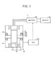
- FIG. 1 is a view of a schematic configuration of a vehicle 1 according to this embodiment.
- the vehicle 1 is a hybrid vehicle that can travel by using power of at least one of a motor M (will be described below) and an engine (not shown).
- a case where the invention is applied to the hybrid vehicle is exemplified.
- the invention can be applied to all types of electric motor vehicles (including, for example, electric vehicles, fuel cell vehicles, and the like in addition to the hybrid vehicles) that travel by using drive power obtained by electric energy.
- the vehicle 1 includes a transaxle 10, an inverter 20, a battery 30, and an electronic control unit (ECU) 100.
- ECU electronice control unit
- a motor M and a bearing 14 are provided in the transaxle 10.
- the motor M is an alternating-current rotary electric machine and representatively a three-phase (U-phase, V-phase, and W-phase) synchronous motor of permanent magnet type.
- the motor M primarily functions as a travel motor that generates drive power for traveling the vehicle 1.
- the motor M may primarily function as a regenerative generator that generates electric power for driving a travel motor.
- the motor M includes a stator 11, a rotor 12, and a rotational shaft 13.
- the stator 11 is fixed to a housing 15 of the transaxle 10.
- the rotor 12 is fixed to the rotational shaft 13 of the motor M.
- the bearing 14 rotatably supports the rotational shaft 13 of the motor M to the housing 15.
- the bearing 14 includes: an inner ring 14a fixed to the rotational shaft 13; an outer ring 14b fixed to the housing 15; and a roller 14c provided between the inner ring 14a and the outer ring 14b.
- Oil for cooling the motor M and lubricating actuation of the bearing 14 is circulated in the transaxle 10.
- the battery 30 is representatively constructed of a secondary battery such as of nickel-hydrogen or lithium-ion or of a storage device such as an electric double-layered capacitor.
- the inverter 20 includes a U-phase arm, a V-phase arm, and a W-phase arm that respectively correspond to each phase of the motor M.
- Each of the phase arms includes plural switching elements (an upper arm and a lower arm), each of which is controlled by a control signal from the ECU 100.
- the inverter 20 converts direct current from the battery 30 to three-phase alternating current and outputs it to the motor M by a switching operation that corresponds to the control signal from the ECU 100. In this way, the motor M is driven.
- the inverter 20 converts the three-phase alternating current that is regenerated by the motor M to the direct current and outputs it to the battery 30 by the switching operation that corresponds to the control signal from the ECU 100. In this way, the battery 30 is charged.
- the vehicle 1 includes plural sensors for detecting various types of physical quantities that are necessary to control the vehicle 1, such as a resolver for detecting a rotational state of the motor M, a sensor for detecting an oil temperature in the transaxle 10, and a sensor for detecting phase current (U-phase current, V-phase current, W-phase current) flowing into the motor M. These sensors output detection results to the ECU 100.
- sensors for detecting various types of physical quantities that are necessary to control the vehicle 1, such as a resolver for detecting a rotational state of the motor M, a sensor for detecting an oil temperature in the transaxle 10, and a sensor for detecting phase current (U-phase current, V-phase current, W-phase current) flowing into the motor M.
- the ECU 100 controls each equipment of the vehicle 1, such as the motor M (the inverter 20).
- the ECU 100 controls output of the motor M such that output (the drive power) of the vehicle 1 becomes output requested by a user (hereinafter also referred to as “user request output”).
- the ECU 100 controls the motor M by pulse width modulation (hereinafter referred to as "PWM") control.
- PWM pulse width modulation
- pseudo sine wave voltage is applied to the each phase of the motor M by controlling the switching operation of the inverter 20 in accordance with a comparison result between a carrier signal and a phase voltage command value. Since the PWM control itself is a known technique, a detailed description on the PWM control will not be made.
- phase current flows between the motor M and the inverter 20.
- This may cause electrolytic corrosion to develop on the bearing 14 that is arranged around a current circuit of the motor M.
- the electrolytic corrosion is a phenomenon that metals around a current circuit are corroded by an intermittent flow of stray current, which is leaked from the current circuit to the outside therearound.
- the output of the motor M is changed in order to suppress the rupture of the oil film, the output (the drive power) of the vehicle 1 may not be able to be maintained at the user request output.
- the ECU 100 performs a process for switching a control mode of the inverter 20, so as to suppress the occurrence of the electrolytic corrosion while maintaining the output of the motor M at the user request output (hereinafter also referred to as a "electrolytic corrosion suppression process").
- the ECU 100 estimates resistance strength of the bearing 14 against the electrolytic corrosion (hereinafter referred to as “strength”) and an electric load applied to the bearing 14 (hereinafter referred to as “stress"). Then, on the basis of the estimated strength and stress, if it is determined that there is a possibility of the occurrence of the electrolytic corrosion, the ECU 100 switches the control mode of the inverter 20 from a normal mode to a electrolytic corrosion suppression mode while maintaining the output of the motor M at the user request output.
- stress resistance strength of the bearing 14 against the electrolytic corrosion
- stress an electric load applied to the bearing 14
- FIG. 2 is a flowchart of the electrolytic corrosion suppression process performed by the ECU 100. This flowchart is repeatedly executed at specified intervals.
- the ECU 100 estimates the strength of the bearing 14 in S10. For example, the ECU 100 estimates a thickness of the oil film in the bearing 14 (hereinafter simply referred to as an "oil film thickness") by using torque and a rotational speed of the motor M as parameters, and then estimates that an insulation property between the elements of the bearing 14 is high and the strength is large (the electrolytic corrosion is less likely to occur) as the estimated oil film thickness is increased.
- an oil film thickness a thickness of the oil film in the bearing 14
- the oil film thickness can also be estimated by using an oil temperature in the transaxle 10 as a parameter. For example, it can be estimated that oil viscosity is high and the oil film thickness is large as the oil temperature in the transaxle 10 is lowered.
- the ECU 100 estimates the stress applied to the bearing 14 in S11. For example, the ECU 100 estimates neutral point voltage and shaft voltage of the motor M from phase voltage of the motor M, and then estimates that the stray current is likely to flow through the bearing 14 and the stress is large (the electrolytic corrosion is likely to occur) as the estimated neutral point voltage and shaft voltage are increased.
- the neutral point voltage is a potential difference between a neutral point of the motor M and a ground
- the shaft voltage is a potential difference between the rotational shaft 13 of the motor M and the ground.
- the ECU 100 determines in S13 whether the electrolytic corrosion of the bearing 14 possibly occurs. The ECU 100 determines that there is a possibility of occurrence of the electrolytic corrosion if the stress estimated in S11 is larger than the strength estimated in S10.
- the ECU 100 controls the inverter 20 in the normal mode in S14.
- the ECU 100 controls the inverter 20 in the electrolytic corrosion suppression mode in S15.
- the electrolytic corrosion suppression mode is a mode for suppressing the occurrence of the electrolytic corrosion more than the normal mode while maintaining the output of the motor M at the user request output.
- a frequency of the carrier signal (hereinafter referred to as a "carrier frequency") that is used for the PWM control of the inverter 20 is switched in accordance with whether the control mode is the normal mode or the electrolytic corrosion suppression mode.
- FIG. 3 includes views of examples of a map for setting the carrier frequency (hereinafter referred to as a "map").
- FIG. 3A shows an example of a map that is used in the normal mode (hereinafter referred to as a "normal mode map”)
- FIG. 3B shows an example of a map that is used during the electrolytic corrosion suppression mode (hereinafter referred to as a “electrolytic corrosion suppression mode map").
- the carrier frequency is set by using the rotational speed and the torque of the motor M as the parameters in both of the normal mode map and the electrolytic corrosion suppression mode map.
- the carrier frequencies in a high torque region ⁇ and a high rotational speed region (3 are set as higher values than those in the normal mode map shown in FIG. 3A .
- the carrier frequencies in the high torque region ⁇ and the high rotational speed region ⁇ in the electrolytic corrosion suppression mode map shown in FIG. 3B are increased to be larger than those in the normal mode map. Accordingly, the frequencies of the neutral point voltage and the shaft voltage of the motor M are no longer included in the frequency region that resonates with the stray current circuit. Thus, the stray current is suppressed, and the electrolytic corrosion is suppressed.
- the output of the motor M is not changed. In other words, the electrolytic corrosion can be suppressed while the output of the motor M is maintained at the user request output.
- the ECU 100 estimates the strength and the stress of the bearing 14 and, on the basis of the estimated strength and stress, determines whether there is a possibility of occurrence of the electrolytic corrosion. Then, if it is determined that there is a possibility of occurrence of the electrolytic corrosion, the ECU 100 switches a carrier frequency setting map from the normal mode map to the electrolytic corrosion suppression mode map, so as to suppress the stray current. In this way, the occurrence of the electrolytic corrosion can be suppressed while the output of the motor M is maintained at the user request output.
- the example in which a target to suppress the electrolytic corrosion is the bearing 14 is described.
- the suppression target of the occurrence of the electrolytic corrosion may be another bearing section or a sliding section in the transaxle 10. In this case, all of the bearing 14 and one of the other bearing section or the sliding section may be set as the target to suppress the electrolytic corrosion.
- the parameter that is used to estimate the strength is the oil film thickness.
- the parameter that can be used to estimate the strength is not limited to this.
- the strength may be estimated on the basis of the surface roughness of a transfer surface of the bearing 14 (hereinafter simply referred to as "surface roughness"). For example, as the surface roughness is larger, a metal contact area in the bearing 14 and an energization frequency are increased. Thus, it can be estimated that the strength is small (the electrolytic corrosion is likely to occur).
- the surface roughness may be used instead of the oil film thickness to estimate the strength, or both of the oil film thickness and the surface roughness may be used to estimate the strength.
- the strength which is estimated on the basis of the oil film thickness or the surface roughness, may be corrected according to the oil temperature, a degree of deterioration of the oil, an amount of foreign matters in the oil, or the like. For example, as the oil temperature is increased, the oil viscosity and the oil film thickness are reduced. Thus, it can be estimated that the strength is small. In addition, as the degree of deterioration of the oil or the amount of foreign matters in the oil is increased, the insulation property of the oil film is deteriorated. Thus, the strength can be corrected to be smaller.
- the example in which the parameters used to estimate the stress are the neutral point voltage and the shaft voltage of the motor M is described.
- the parameter that can be used to estimate the stress is not limited to these.
- the stress may be estimated on the basis of the current flowing through the motor M or alternating-current electric power (unit: Watt) supplied to the motor M.
- alternating-current electric power supplied to the motor M an effective value of the alternating-current electric power or a maximum value of the alternating-current electric power may be used.
- current density When the current flowing through the motor M is used, current density may be used.
- the stress may be estimated on the basis of the current flowing through the motor M and the alternating-current electric power supplied to the motor M instead of the neutral point voltage and the shaft voltage of the motor M.
- the stress may be estimated on the basis of all of the neutral point voltage and the shaft voltage of the motor M, the current flowing through the motor M, and the alternating-current electric power supplied to the motor M.
- the electrolytic corrosion possibly occurs if the stress is larger than a prescribed value that is determined in advance.
- the carrier frequency is changed to be included in a high frequency region (see above-described FIG. 3 ).
- a condition for changing the carrier frequency is not limited to this.
- Condition 2 In the case where the oil temperature is high (Condition 2) or where an elapsed time period (aged deterioration) exceeds a threshold (Condition 3), it may be determined that the insulation property of the oil film is reduced, and thus the carrier frequency may be changed to the high frequency region.
- Condition 3 instead of Condition 1, at least one of Condition 2 and Condition 3 may be used, or all of Conditions 1, 2, and 3 may be used.
- a target to be changed by the electrolytic corrosion suppression process is not limited to the carrier frequency.
- a voltage waveform output from the inverter 20 to the motor M may be changed.
- a control method of the motor M can be switched to any one of PWM control method, overmodulation PWM control method, square-wave voltage control method, and the electrolytic corrosion may be suppressed by changing the method among these control methods.
- the control method of the motor M may be changed from the square-wave voltage control method to the overmodulation PWM control method or from the overmodulation PWM control method to the PWM control method.
- the operation point of the motor M may be changed.
- the operation point of the motor M when the operation point of the motor M is included in the high-output region where the electrolytic corrosion is likely to occur, at least the torque or the rotational speed of the motor M is reduced. In this way, the stress is reduced, and the electrolytic corrosion can be suppressed.
- a reduced amount when the output of the motor M is reduced, a reduced amount may be compensated by output of the engine.
- suppression of the electrolytic corrosion may be prioritized, and drive power of the vehicle 1 may be limited.
Landscapes
- Engineering & Computer Science (AREA)
- Power Engineering (AREA)
- Transportation (AREA)
- Mechanical Engineering (AREA)
- Sustainable Energy (AREA)
- Sustainable Development (AREA)
- Life Sciences & Earth Sciences (AREA)
- Microelectronics & Electronic Packaging (AREA)
- Chemical & Material Sciences (AREA)
- Combustion & Propulsion (AREA)
- Control Of Ac Motors In General (AREA)
- Motor Or Generator Frames (AREA)
- Electric Propulsion And Braking For Vehicles (AREA)
- Inverter Devices (AREA)
- Rolling Contact Bearings (AREA)
Abstract
Description
- The invention relates to a vehicle, and particularly relates to a vehicle that includes a rotary electric machine and an inverter for supplying current to the rotary electric machine.
- A technique of suppressing rupture of an oil film is disclosed in Published Japanese Translation of
PCT application No. 2008-539682 JP 2008-539682 A - By the way, it has conventionally been known that a phenomenon called electrolytic corrosion occurs to metals around the motor once the motor is driven. The metals around the motor refer to the bearing for supporting the rotational shaft of the motor and the like. The electrolytic corrosion is a phenomenon that metals around a current circuit are corroded by an intermittent flow of stray current, which is leaked from the current circuit to the outside therearound.
- In order to suppress occurrence of the electrolytic corrosion, it is desirable to form an insulation oil film on a surface of each metal around the motor and suppress rupture of the oil film. However, in order to suppress the rupture of the oil film and thereby the occurrence of the electrolytic corrosion, if the rotational speed of the motor is increased to the specified value as described in
JP 2008-539682 A - The invention provides a vehicle that suppresses occurrence of electrolytic corrosion in a peripheral portion of a rotary electric machine while maintaining output of the rotary electric machine at user request output.
- A vehicle related to the present invention comprises a rotary electric machine, an inverter and an electronic control unit. The inverter is configured to supply current to the rotary electric machine. The electronic control unit is configured to control the inverter. The electronic control unit is configured to determine whether there is a possibility of occurrence of electrolytic corrosion in a peripheral portion of the rotary electric machine. The electronic control unit is configured to set a control mode of the inverter to a first mode on a condition that the electronic control unit determines that there is no possibility of occurrence of the electrolytic corrosion. The electronic control unit is configured to set the control mode of the inverter to a second mode and maintain output of the rotary electric machine at user request output on a condition that the electronic control unit determines that there is a possibility of occurrence of the electrolytic corrosion. The second mode is a mode in which occurrence of the electrolytic corrosion is further suppressed compared to the first mode.
- According to such a configuration, if it is determined that the electrolytic corrosion occurs, the control mode of the inverter is switched from the first mode to the second mode. The second mode is a mode in which the occurrence of the electrolytic corrosion is further suppressed compared to the first mode while the output of the rotary electric machine is maintained at the user request output. Thus, occurrence of the electrolytic corrosion can be suppressed while the output of the rotary electric machine is maintained at the user request output.
- The electronic control unit may be configured to control the inverter by pulse width modulation control. The second mode may be a mode in which a frequency of a carrier signal is set to a frequency that further suppresses the occurrence of the electrolytic corrosion compared to the first mode and output of the rotary electric machine (M) is maintained at the user request output. The carrier signal may be used for the pulse width modulation control.
- According to such a configuration, by changing the frequency of a carrier signal used for the pulse width modulation control of the inverter, the occurrence of the electrolytic corrosion can be suppressed while the output of the rotary electric machine is maintained at the user request output.
- The electronic control unit may be configured to estimate strength and stress based on an operation state of the rotary electric machine. The electronic control unit may be configured to determine whether there is a possibility of occurrence of the electrolytic corrosion based on an estimated strength and stress. The strength may indicate resistance strength of the peripheral portion against the electrolytic corrosion. The stress may indicate an electric load applied to the peripheral portion.
- According to such a configuration, it is possible to appropriately determine whether the electrolytic corrosion occurs in consideration of both of the resistance strength of the peripheral portion against the electrolytic corrosion (the strength) and the electric load on the peripheral portion (the stress).
- The vehicle may be a hybrid vehicle that includes a travel motor and a regenerative generator. The rotary electric machine may be at least one of the travel motor or the regenerative generator.
- According to such a configuration, the occurrence of the electrolytic corrosion can be suppressed while the output of the travel motor or the regenerative generator is maintained at the user request output.
- Features, advantages, and technical and industrial significance of exemplary embodiments of the invention will be described below with reference to the accompanying drawings, in which like numerals denote like elements, and wherein:
-
FIG. 1 is a view of a schematic configuration of a vehicle; -
FIG. 2 is a flowchart of a process performed by an ECU; -
FIG. 3A is a view of an example of a carrier frequency setting map; and -
FIG. 3B is a view of another example of the carrier frequency setting map. - A description will hereinafter be made on an embodiment of the invention with reference to the drawings. In the following description, the same components are denoted by the same reference numerals. Names and functions thereof are also the same. Therefore, a detailed description thereof will not be repeated.
-
FIG. 1 is a view of a schematic configuration of avehicle 1 according to this embodiment. Thevehicle 1 is a hybrid vehicle that can travel by using power of at least one of a motor M (will be described below) and an engine (not shown). In this embodiment, a case where the invention is applied to the hybrid vehicle is exemplified. However, the invention can be applied to all types of electric motor vehicles (including, for example, electric vehicles, fuel cell vehicles, and the like in addition to the hybrid vehicles) that travel by using drive power obtained by electric energy. - The
vehicle 1 includes atransaxle 10, aninverter 20, abattery 30, and an electronic control unit (ECU) 100. A motor M and abearing 14 are provided in thetransaxle 10. - The motor M is an alternating-current rotary electric machine and representatively a three-phase (U-phase, V-phase, and W-phase) synchronous motor of permanent magnet type. The motor M primarily functions as a travel motor that generates drive power for traveling the
vehicle 1. However, the motor M may primarily function as a regenerative generator that generates electric power for driving a travel motor. - The motor M includes a
stator 11, arotor 12, and arotational shaft 13. Thestator 11 is fixed to ahousing 15 of thetransaxle 10. Therotor 12 is fixed to therotational shaft 13 of the motor M. - The bearing 14 rotatably supports the
rotational shaft 13 of the motor M to thehousing 15. Thebearing 14 includes: aninner ring 14a fixed to therotational shaft 13; anouter ring 14b fixed to thehousing 15; and aroller 14c provided between theinner ring 14a and theouter ring 14b. - Oil for cooling the motor M and lubricating actuation of the
bearing 14 is circulated in thetransaxle 10. - The
battery 30 is representatively constructed of a secondary battery such as of nickel-hydrogen or lithium-ion or of a storage device such as an electric double-layered capacitor. - The
inverter 20 includes a U-phase arm, a V-phase arm, and a W-phase arm that respectively correspond to each phase of the motor M. Each of the phase arms includes plural switching elements (an upper arm and a lower arm), each of which is controlled by a control signal from theECU 100. - When the motor M functions as the motor, the
inverter 20 converts direct current from thebattery 30 to three-phase alternating current and outputs it to the motor M by a switching operation that corresponds to the control signal from theECU 100. In this way, the motor M is driven. - Meanwhile, when the motor M functions as a generator, the
inverter 20 converts the three-phase alternating current that is regenerated by the motor M to the direct current and outputs it to thebattery 30 by the switching operation that corresponds to the control signal from theECU 100. In this way, thebattery 30 is charged. - Furthermore, although not shown, the
vehicle 1 includes plural sensors for detecting various types of physical quantities that are necessary to control thevehicle 1, such as a resolver for detecting a rotational state of the motor M, a sensor for detecting an oil temperature in thetransaxle 10, and a sensor for detecting phase current (U-phase current, V-phase current, W-phase current) flowing into the motor M. These sensors output detection results to theECU 100. - A central processing unit (CPU) and a memory, which are not shown, are installed in the
ECU 100. On the basis of the information stored in said memory and information from each of the sensors, theECU 100 controls each equipment of thevehicle 1, such as the motor M (the inverter 20). - The
ECU 100 controls output of the motor M such that output (the drive power) of thevehicle 1 becomes output requested by a user (hereinafter also referred to as "user request output"). TheECU 100 controls the motor M by pulse width modulation (hereinafter referred to as "PWM") control. In the PWM control, pseudo sine wave voltage is applied to the each phase of the motor M by controlling the switching operation of theinverter 20 in accordance with a comparison result between a carrier signal and a phase voltage command value. Since the PWM control itself is a known technique, a detailed description on the PWM control will not be made. - In the
vehicle 1 that has the configuration as described above, when the motor M is driven, phase current flows between the motor M and theinverter 20. This may cause electrolytic corrosion to develop on thebearing 14 that is arranged around a current circuit of the motor M. As already described, the electrolytic corrosion is a phenomenon that metals around a current circuit are corroded by an intermittent flow of stray current, which is leaked from the current circuit to the outside therearound. - In order to suppress occurrence of the electrolytic corrosion of the
bearing 14, it is preferred to prevent rupture of an oil film in the bearing 14 (more specifically, an oil film formed between the elements, theroller 14c, theinner ring 14a, and theouter ring 14b of the bearing 14). However, if the output of the motor M is changed in order to suppress the rupture of the oil film, the output (the drive power) of thevehicle 1 may not be able to be maintained at the user request output. - In view of the above, the
ECU 100 according to this embodiment performs a process for switching a control mode of theinverter 20, so as to suppress the occurrence of the electrolytic corrosion while maintaining the output of the motor M at the user request output (hereinafter also referred to as a "electrolytic corrosion suppression process"). - More specifically, the
ECU 100 estimates resistance strength of thebearing 14 against the electrolytic corrosion (hereinafter referred to as "strength") and an electric load applied to the bearing 14 (hereinafter referred to as "stress"). Then, on the basis of the estimated strength and stress, if it is determined that there is a possibility of the occurrence of the electrolytic corrosion, theECU 100 switches the control mode of theinverter 20 from a normal mode to a electrolytic corrosion suppression mode while maintaining the output of the motor M at the user request output. -
FIG. 2 is a flowchart of the electrolytic corrosion suppression process performed by theECU 100. This flowchart is repeatedly executed at specified intervals. - The
ECU 100 estimates the strength of the bearing 14 in S10. For example, theECU 100 estimates a thickness of the oil film in the bearing 14 (hereinafter simply referred to as an "oil film thickness") by using torque and a rotational speed of the motor M as parameters, and then estimates that an insulation property between the elements of thebearing 14 is high and the strength is large (the electrolytic corrosion is less likely to occur) as the estimated oil film thickness is increased. - It should be noted that the oil film thickness can also be estimated by using an oil temperature in the
transaxle 10 as a parameter. For example, it can be estimated that oil viscosity is high and the oil film thickness is large as the oil temperature in thetransaxle 10 is lowered. - The
ECU 100 estimates the stress applied to thebearing 14 in S11. For example, theECU 100 estimates neutral point voltage and shaft voltage of the motor M from phase voltage of the motor M, and then estimates that the stray current is likely to flow through thebearing 14 and the stress is large (the electrolytic corrosion is likely to occur) as the estimated neutral point voltage and shaft voltage are increased. The neutral point voltage is a potential difference between a neutral point of the motor M and a ground, and the shaft voltage is a potential difference between therotational shaft 13 of the motor M and the ground. - The
ECU 100 determines in S13 whether the electrolytic corrosion of thebearing 14 possibly occurs. TheECU 100 determines that there is a possibility of occurrence of the electrolytic corrosion if the stress estimated in S11 is larger than the strength estimated in S10. - If it is not determined that the electrolytic corrosion possibly occurs (NO in S13), the
ECU 100 controls theinverter 20 in the normal mode in S14. - On the contrary, if it is determined that there is a possibility of occurrence of the electrolytic corrosion (YES in S13), the
ECU 100 controls theinverter 20 in the electrolytic corrosion suppression mode in S15. The electrolytic corrosion suppression mode is a mode for suppressing the occurrence of the electrolytic corrosion more than the normal mode while maintaining the output of the motor M at the user request output. - In this embodiment, a frequency of the carrier signal (hereinafter referred to as a "carrier frequency") that is used for the PWM control of the
inverter 20 is switched in accordance with whether the control mode is the normal mode or the electrolytic corrosion suppression mode. -
FIG. 3 includes views of examples of a map for setting the carrier frequency (hereinafter referred to as a "map").FIG. 3A shows an example of a map that is used in the normal mode (hereinafter referred to as a "normal mode map"), andFIG. 3B shows an example of a map that is used during the electrolytic corrosion suppression mode (hereinafter referred to as a "electrolytic corrosion suppression mode map"). - As shown in
FIG. 3A and FIG. 3B , the carrier frequency is set by using the rotational speed and the torque of the motor M as the parameters in both of the normal mode map and the electrolytic corrosion suppression mode map. - In the electrolytic corrosion suppression mode map shown in
FIG. 3B , the carrier frequencies in a high torque region α and a high rotational speed region (3 are set as higher values than those in the normal mode map shown inFIG. 3A . - It has been identified by an experiment and the like that, if the carrier frequencies in the high torque region α and the high rotational speed region β are set in the normal mode map shown in
FIG. 3A , frequencies of the neutral point voltage and the shaft voltage of the motor M are included in a frequency region that resonates with the stray current circuit and thus the stray current tends to be increased. - Due to the above reason, the carrier frequencies in the high torque region α and the high rotational speed region β in the electrolytic corrosion suppression mode map shown in
FIG. 3B are increased to be larger than those in the normal mode map. Accordingly, the frequencies of the neutral point voltage and the shaft voltage of the motor M are no longer included in the frequency region that resonates with the stray current circuit. Thus, the stray current is suppressed, and the electrolytic corrosion is suppressed. Here, even when the carrier frequency is changed, the output of the motor M is not changed. In other words, the electrolytic corrosion can be suppressed while the output of the motor M is maintained at the user request output. - As it has been described so far, the
ECU 100 according to this embodiment estimates the strength and the stress of thebearing 14 and, on the basis of the estimated strength and stress, determines whether there is a possibility of occurrence of the electrolytic corrosion. Then, if it is determined that there is a possibility of occurrence of the electrolytic corrosion, theECU 100 switches a carrier frequency setting map from the normal mode map to the electrolytic corrosion suppression mode map, so as to suppress the stray current. In this way, the occurrence of the electrolytic corrosion can be suppressed while the output of the motor M is maintained at the user request output. - The above-described embodiment can be modified as follows, for example.
- In the above-described embodiment, the example in which a target to suppress the electrolytic corrosion is the
bearing 14 is described. However, instead of thebearing 14, the suppression target of the occurrence of the electrolytic corrosion may be another bearing section or a sliding section in thetransaxle 10. In this case, all of thebearing 14 and one of the other bearing section or the sliding section may be set as the target to suppress the electrolytic corrosion. - In the above-described embodiment, the example in which the parameter that is used to estimate the strength is the oil film thickness is described. However, the parameter that can be used to estimate the strength is not limited to this.
- For example, the strength may be estimated on the basis of the surface roughness of a transfer surface of the bearing 14 (hereinafter simply referred to as "surface roughness"). For example, as the surface roughness is larger, a metal contact area in the
bearing 14 and an energization frequency are increased. Thus, it can be estimated that the strength is small (the electrolytic corrosion is likely to occur). In this case, the surface roughness may be used instead of the oil film thickness to estimate the strength, or both of the oil film thickness and the surface roughness may be used to estimate the strength. - In addition, the strength, which is estimated on the basis of the oil film thickness or the surface roughness, may be corrected according to the oil temperature, a degree of deterioration of the oil, an amount of foreign matters in the oil, or the like. For example, as the oil temperature is increased, the oil viscosity and the oil film thickness are reduced. Thus, it can be estimated that the strength is small. In addition, as the degree of deterioration of the oil or the amount of foreign matters in the oil is increased, the insulation property of the oil film is deteriorated. Thus, the strength can be corrected to be smaller.
- In the above-described embodiment, the example in which the parameters used to estimate the stress are the neutral point voltage and the shaft voltage of the motor M is described. However, the parameter that can be used to estimate the stress is not limited to these.
- For example, the stress may be estimated on the basis of the current flowing through the motor M or alternating-current electric power (unit: Watt) supplied to the motor M. When the alternating-current electric power supplied to the motor M is used, an effective value of the alternating-current electric power or a maximum value of the alternating-current electric power may be used. When the current flowing through the motor M is used, current density may be used. In this case, the stress may be estimated on the basis of the current flowing through the motor M and the alternating-current electric power supplied to the motor M instead of the neutral point voltage and the shaft voltage of the motor M. In addition, the stress may be estimated on the basis of all of the neutral point voltage and the shaft voltage of the motor M, the current flowing through the motor M, and the alternating-current electric power supplied to the motor M.
- In the above-described embodiment, it is determined that there is a possibility of occurrence of the electrolytic corrosion if the stress is larger than the strength. However, a method for determining whether the electrolytic corrosion possibly occurs is not limited to this.
- For example, it may be determined that the electrolytic corrosion possibly occurs if the stress is larger than a prescribed value that is determined in advance. Alternatively, it may be determined that there is a possibility of occurrence of the electrolytic corrosion if the stress is smaller than a prescribed value that is determined in advance.
- In the above-described embodiment, in the case where it is determined that there is a possibility of occurrence of the electrolytic corrosion, and where the motor M is operated in the high torque region or the high rotational speed region (Condition 1), the carrier frequency is changed to be included in a high frequency region (see above-described
FIG. 3 ). However, a condition for changing the carrier frequency is not limited to this. - For example, in the case where the oil temperature is high (Condition 2) or where an elapsed time period (aged deterioration) exceeds a threshold (Condition 3), it may be determined that the insulation property of the oil film is reduced, and thus the carrier frequency may be changed to the high frequency region. In this case, instead of
Condition 1, at least one of Condition 2 and Condition 3 may be used, or all ofConditions 1, 2, and 3 may be used. - In the above-described embodiment, the example in which the carrier frequency is changed by the electrolytic corrosion suppression process is described. However, a target to be changed by the electrolytic corrosion suppression process is not limited to the carrier frequency.
- For example, a voltage waveform output from the
inverter 20 to the motor M may be changed. When a control method of the motor M can be switched to any one of PWM control method, overmodulation PWM control method, square-wave voltage control method, and the electrolytic corrosion may be suppressed by changing the method among these control methods. For example, when an operation point of the motor M is included in a high-output region, the control method of the motor M may be changed from the square-wave voltage control method to the overmodulation PWM control method or from the overmodulation PWM control method to the PWM control method. By changing the control method of the motor M just as described, the output voltage waveform of the motor M is changed, and thus a degree of current waveform distortion can be minimized. In this way, instantaneous peak voltage and peak current are suppressed. Therefore, the electrolytic corrosion can be suppressed. - In addition, the operation point of the motor M may be changed. In other words, when the operation point of the motor M is included in the high-output region where the electrolytic corrosion is likely to occur, at least the torque or the rotational speed of the motor M is reduced. In this way, the stress is reduced, and the electrolytic corrosion can be suppressed. It should be noted that, when the output of the motor M is reduced, a reduced amount may be compensated by output of the engine. When the reduced amount of the output of the motor M cannot be compensated by output of the engine, suppression of the electrolytic corrosion may be prioritized, and drive power of the
vehicle 1 may be limited. - The above-described embodiment and the modifications thereof can appropriately be combined within a range that technical contradiction does not arise.
- It should be understood that the embodiment disclosed herein is merely illustrative and not restrictive. The scope of the invention is defined by the claims rather than by the above description, and it is intended to include all modifications falling within the scope of the claims and equivalents thereof.
Claims (4)
- A vehicle (1) characterized in that it comprises:a rotary electric machine (M);an inverter (20) configured to supply current to the rotary electric machine (M); andan electronic control unit (100) configured to control the inverter (20), the electronic control unit (100) configured to determine whether there is a possibility of occurrence of electrolytic corrosion in a peripheral portion of the rotary electric machine (M), the electronic control unit (100) configured to set a control mode of the inverter (20) to a first mode on a condition that the electronic control unit (100) determines that there is no possibility of occurrence of the electrolytic corrosion, the electronic control unit (100) configured to set the control mode of the inverter (20) to a second mode and maintain output of the rotary electric machine (M) at user request output on a condition that the electronic control unit (100) determines that there is a possibility of occurrence of the electrolytic corrosion, and the second mode being a mode in which occurrence of the electrolytic corrosion is further suppressed compared to the first mode.
- The vehicle (1) according to claim 1, wherein
the electronic control unit (100) is configured to control the inverter (20) by pulse width modulation control,
the second mode is a mode in which a frequency of a carrier signal is set to a frequency that further suppresses the occurrence of the electrolytic corrosion compared to the first mode and output of the rotary electric machine (M) is maintained at the user request output, and
the carrier signal is used for the pulse width modulation control. - The vehicle (1) according to claim 1 or 2, wherein
the electronic control unit (100) is configured to estimate strength and stress based on an operation state of the rotary electric machine (M), the electronic control unit (100) is configured to determine whether there is a possibility of occurrence of the electrolytic corrosion based on an estimated strength and stress,
the strength indicates resistance strength of the peripheral portion against the electrolytic corrosion, and
the stress indicates an electric load applied to the peripheral portion. - The vehicle (1) according to any one of claims 1 to 3, wherein
the vehicle (1) is a hybrid vehicle that includes a travel motor and a regenerative generator, and
the rotary electric machine (M) is at least one of the travel motor or the regenerative generator.
Applications Claiming Priority (1)
| Application Number | Priority Date | Filing Date | Title |
|---|---|---|---|
| JP2014092689A JP5994812B2 (en) | 2014-04-28 | 2014-04-28 | vehicle |
Publications (3)
| Publication Number | Publication Date |
|---|---|
| EP2940861A2 true EP2940861A2 (en) | 2015-11-04 |
| EP2940861A3 EP2940861A3 (en) | 2016-04-27 |
| EP2940861B1 EP2940861B1 (en) | 2022-03-09 |
Family
ID=53039293
Family Applications (1)
| Application Number | Title | Priority Date | Filing Date |
|---|---|---|---|
| EP15165516.4A Active EP2940861B1 (en) | 2014-04-28 | 2015-04-28 | Vehicle |
Country Status (4)
| Country | Link |
|---|---|
| US (1) | US9358970B2 (en) |
| EP (1) | EP2940861B1 (en) |
| JP (1) | JP5994812B2 (en) |
| CN (1) | CN105034850B (en) |
Cited By (1)
| Publication number | Priority date | Publication date | Assignee | Title |
|---|---|---|---|---|
| WO2021018829A1 (en) * | 2019-07-29 | 2021-02-04 | Valeo Siemens Eautomotive Germany Gmbh | Control device, inverter, assembly having an inverter and an electric machine, method for operating an inverter and computer program |
Families Citing this family (4)
| Publication number | Priority date | Publication date | Assignee | Title |
|---|---|---|---|---|
| JP5994812B2 (en) * | 2014-04-28 | 2016-09-21 | トヨタ自動車株式会社 | vehicle |
| JP6428737B2 (en) * | 2016-09-29 | 2018-11-28 | トヨタ自動車株式会社 | Rotating electrical machine system |
| JP7296913B2 (en) * | 2020-04-10 | 2023-06-23 | 三菱電機株式会社 | pulse width modulation controller |
| CN114454721B (en) * | 2022-03-30 | 2024-07-19 | 广汽埃安新能源汽车有限公司 | Method for reducing electric corrosion of motor bearing of electric automobile and electric automobile |
Citations (1)
| Publication number | Priority date | Publication date | Assignee | Title |
|---|---|---|---|---|
| JP2008539682A (en) | 2005-04-29 | 2008-11-13 | ファールプール・ソシエダッド・アノニマ | Control system and method for protecting lubricating films in multiple bearings of a compressor from breakage |
Family Cites Families (26)
| Publication number | Priority date | Publication date | Assignee | Title |
|---|---|---|---|---|
| US4840719A (en) * | 1984-08-31 | 1989-06-20 | Cities Service Oil And Gas Corporation | Corrosion probe and method for measuring corrosion rates |
| KR910008548B1 (en) * | 1987-05-07 | 1991-10-18 | 가부시키가이샤 히타치세이사쿠쇼 | Voltage regulator of charging generator |
| US5672050A (en) * | 1995-08-04 | 1997-09-30 | Lynx Electronics, Inc. | Apparatus and method for monitoring a sump pump |
| JP3480802B2 (en) * | 1998-02-12 | 2003-12-22 | 東芝エンジニアリング株式会社 | Motor equipment |
| US6434512B1 (en) * | 1998-04-02 | 2002-08-13 | Reliance Electric Technologies, Llc | Modular data collection and analysis system |
| US6894448B2 (en) * | 2003-06-12 | 2005-05-17 | International Truck Intellectual Property Company, Llc | Direct current motor condition monitoring and exercising system |
| JP2005006466A (en) * | 2003-06-13 | 2005-01-06 | Mitsubishi Electric Corp | Drive method, drive system, and PWM inverter device |
| US20060125493A1 (en) * | 2004-12-13 | 2006-06-15 | Materials Modification, Inc. | Corrosion sensor and method of monitoring corrosion |
| KR20080056188A (en) * | 2005-09-05 | 2008-06-20 | 아이디어쏘시에이트 (아이오엠) 엘티디. | How to control mechanically commutated electric motors |
| JP2008005659A (en) * | 2006-06-23 | 2008-01-10 | Toyota Motor Corp | Electric vehicle |
| DE112008001121T5 (en) * | 2007-04-27 | 2010-04-08 | Ntn Corporation | Grease composition and grease lubricated bearing |
| CN201044422Y (en) * | 2007-05-09 | 2008-04-02 | 乐星产电(无锡)有限公司 | Intelligent general frequency converter |
| WO2009001546A1 (en) * | 2007-06-25 | 2008-12-31 | Panasonic Corporation | Electric motor, and electric device having the motor |
| US7990097B2 (en) * | 2008-09-29 | 2011-08-02 | Rockwell Automation Technologies, Inc. | Power conversion system and method for active damping of common mode resonance |
| JP5557441B2 (en) * | 2008-10-31 | 2014-07-23 | 日立オートモティブシステムズ株式会社 | Power converter and electric vehicle |
| US20130038182A1 (en) * | 2010-03-17 | 2013-02-14 | Hitachi, Ltd. | Inverter-driven dynamo electric machine and system, bearing, and end bracket for same |
| US20110240893A1 (en) * | 2010-04-02 | 2011-10-06 | Schneider Electric Buildings, Llc | Valve Actuator Having Synchronous Motor Having Plastic Bushings |
| JP5508943B2 (en) * | 2010-06-07 | 2014-06-04 | 株式会社日立産機システム | Power converter |
| JP5320356B2 (en) | 2010-08-02 | 2013-10-23 | 株式会社日立産機システム | Power converter |
| JP5432097B2 (en) | 2010-09-10 | 2014-03-05 | 株式会社日立産機システム | Inverter-driven rotating electrical machine system |
| AU2011303259B2 (en) * | 2010-09-15 | 2014-08-14 | Mitsubishi Electric Corporation | Power conversion device, motor containing same, air conditioner containing motor, and ventilation fan containing motor |
| WO2013098940A1 (en) * | 2011-12-27 | 2013-07-04 | 三菱電機株式会社 | Electric motor |
| JP2013158091A (en) * | 2012-01-27 | 2013-08-15 | Toyota Motor Corp | Dynamo-electric machine control system |
| JP5755599B2 (en) * | 2012-05-15 | 2015-07-29 | 株式会社ダイヤメット | Sintered bearing for motor-type fuel pump with excellent corrosion resistance, wear resistance and conformability |
| KR101442414B1 (en) * | 2013-05-23 | 2014-09-24 | 뉴모텍(주) | Ground structure for motor |
| JP5994812B2 (en) * | 2014-04-28 | 2016-09-21 | トヨタ自動車株式会社 | vehicle |
-
2014
- 2014-04-28 JP JP2014092689A patent/JP5994812B2/en active Active
-
2015
- 2015-04-23 US US14/694,182 patent/US9358970B2/en active Active
- 2015-04-24 CN CN201510202206.7A patent/CN105034850B/en active Active
- 2015-04-28 EP EP15165516.4A patent/EP2940861B1/en active Active
Patent Citations (1)
| Publication number | Priority date | Publication date | Assignee | Title |
|---|---|---|---|---|
| JP2008539682A (en) | 2005-04-29 | 2008-11-13 | ファールプール・ソシエダッド・アノニマ | Control system and method for protecting lubricating films in multiple bearings of a compressor from breakage |
Cited By (2)
| Publication number | Priority date | Publication date | Assignee | Title |
|---|---|---|---|---|
| WO2021018829A1 (en) * | 2019-07-29 | 2021-02-04 | Valeo Siemens Eautomotive Germany Gmbh | Control device, inverter, assembly having an inverter and an electric machine, method for operating an inverter and computer program |
| US12027998B2 (en) | 2019-07-29 | 2024-07-02 | Valeo Siemens Eautomotive Germany Gmbh | Control device, inverter, assembly having an inverter and an electric machine, method for operating an inverter and computer program |
Also Published As
| Publication number | Publication date |
|---|---|
| US9358970B2 (en) | 2016-06-07 |
| EP2940861A3 (en) | 2016-04-27 |
| EP2940861B1 (en) | 2022-03-09 |
| CN105034850B (en) | 2017-07-18 |
| CN105034850A (en) | 2015-11-11 |
| JP2015211582A (en) | 2015-11-24 |
| JP5994812B2 (en) | 2016-09-21 |
| US20150307078A1 (en) | 2015-10-29 |
Similar Documents
| Publication | Publication Date | Title |
|---|---|---|
| US10351002B2 (en) | Inverter control device and vehicle control device | |
| CN106029430B (en) | Power supply unit for electric vehicles | |
| KR101405223B1 (en) | Offset compensation method of current sensor and motor drive system | |
| CN103222184B (en) | For making the method and apparatus of separately excited machine operation | |
| EP2940861B1 (en) | Vehicle | |
| US20130343105A1 (en) | Inverter overheating protection control apparatus and inverter overheating protection control method | |
| US20130063061A1 (en) | Motor drive apparatus and vehicle with the same mounted thereon | |
| JP2009171640A (en) | Electric motor drive control device, drive control method, and electric vehicle | |
| CN106064569B (en) | Electric vehicle | |
| JP6190327B2 (en) | Electric motor control system | |
| US8928263B2 (en) | Control apparatus in motor drive system and method of controlling motor drive system | |
| JP5924702B2 (en) | Power generation control device for hybrid vehicle and power generation control method for hybrid vehicle | |
| US10601359B2 (en) | Motor-control device | |
| WO2017183699A1 (en) | Control device for dynamoelectric machine | |
| US10855219B2 (en) | Drive device | |
| JP2018102102A (en) | Motor system | |
| JP2014183662A (en) | Vehicle control device | |
| JP5862504B2 (en) | Vehicle control apparatus and vehicle | |
| JP7059634B2 (en) | Power system | |
| JP2016208686A (en) | Electric vehicle | |
| JP2015211533A (en) | Control device and control method for motor vehicle | |
| JP2012222907A (en) | Electric vehicle | |
| JP5724308B2 (en) | Drive device | |
| JP2017112725A (en) | Motor equipment | |
| JP5696743B2 (en) | Rotating electrical machine control system |
Legal Events
| Date | Code | Title | Description |
|---|---|---|---|
| PUAI | Public reference made under article 153(3) epc to a published international application that has entered the european phase |
Free format text: ORIGINAL CODE: 0009012 |
|
| 17P | Request for examination filed |
Effective date: 20150428 |
|
| AK | Designated contracting states |
Kind code of ref document: A2 Designated state(s): AL AT BE BG CH CY CZ DE DK EE ES FI FR GB GR HR HU IE IS IT LI LT LU LV MC MK MT NL NO PL PT RO RS SE SI SK SM TR |
|
| AX | Request for extension of the european patent |
Extension state: BA ME |
|
| PUAL | Search report despatched |
Free format text: ORIGINAL CODE: 0009013 |
|
| AK | Designated contracting states |
Kind code of ref document: A3 Designated state(s): AL AT BE BG CH CY CZ DE DK EE ES FI FR GB GR HR HU IE IS IT LI LT LU LV MC MK MT NL NO PL PT RO RS SE SI SK SM TR |
|
| AX | Request for extension of the european patent |
Extension state: BA ME |
|
| RIC1 | Information provided on ipc code assigned before grant |
Ipc: B60L 7/14 20060101ALI20160321BHEP Ipc: H02K 5/173 20060101ALN20160321BHEP Ipc: B60L 11/18 20060101ALI20160321BHEP Ipc: H02P 27/08 20060101AFI20160321BHEP Ipc: F04C 29/02 20060101ALN20160321BHEP Ipc: H02P 29/00 20160101ALI20160321BHEP Ipc: B60L 3/00 20060101ALI20160321BHEP Ipc: B60W 10/08 20060101ALI20160321BHEP Ipc: B60L 11/00 20060101ALN20160321BHEP |
|
| STAA | Information on the status of an ep patent application or granted ep patent |
Free format text: STATUS: EXAMINATION IS IN PROGRESS |
|
| 17Q | First examination report despatched |
Effective date: 20191115 |
|
| RAP1 | Party data changed (applicant data changed or rights of an application transferred) |
Owner name: DENSO CORPORATION |
|
| GRAP | Despatch of communication of intention to grant a patent |
Free format text: ORIGINAL CODE: EPIDOSNIGR1 |
|
| STAA | Information on the status of an ep patent application or granted ep patent |
Free format text: STATUS: GRANT OF PATENT IS INTENDED |
|
| RIC1 | Information provided on ipc code assigned before grant |
Ipc: H02K 5/173 20060101ALN20210930BHEP Ipc: F04C 29/02 20060101ALN20210930BHEP Ipc: B60L 50/51 20190101ALI20210930BHEP Ipc: B60L 50/40 20190101ALI20210930BHEP Ipc: B60W 10/08 20060101ALI20210930BHEP Ipc: B60L 7/14 20060101ALI20210930BHEP Ipc: B60L 3/00 20190101ALI20210930BHEP Ipc: H02P 29/00 20160101ALI20210930BHEP Ipc: H02P 27/08 20060101AFI20210930BHEP |
|
| INTG | Intention to grant announced |
Effective date: 20211018 |
|
| GRAS | Grant fee paid |
Free format text: ORIGINAL CODE: EPIDOSNIGR3 |
|
| GRAA | (expected) grant |
Free format text: ORIGINAL CODE: 0009210 |
|
| STAA | Information on the status of an ep patent application or granted ep patent |
Free format text: STATUS: THE PATENT HAS BEEN GRANTED |
|
| AK | Designated contracting states |
Kind code of ref document: B1 Designated state(s): AL AT BE BG CH CY CZ DE DK EE ES FI FR GB GR HR HU IE IS IT LI LT LU LV MC MK MT NL NO PL PT RO RS SE SI SK SM TR |
|
| REG | Reference to a national code |
Ref country code: GB Ref legal event code: FG4D |
|
| REG | Reference to a national code |
Ref country code: CH Ref legal event code: EP Ref country code: AT Ref legal event code: REF Ref document number: 1474972 Country of ref document: AT Kind code of ref document: T Effective date: 20220315 |
|
| REG | Reference to a national code |
Ref country code: DE Ref legal event code: R096 Ref document number: 602015077360 Country of ref document: DE |
|
| REG | Reference to a national code |
Ref country code: IE Ref legal event code: FG4D |
|
| REG | Reference to a national code |
Ref country code: LT Ref legal event code: MG9D |
|
| REG | Reference to a national code |
Ref country code: NL Ref legal event code: MP Effective date: 20220309 |
|
| PG25 | Lapsed in a contracting state [announced via postgrant information from national office to epo] |
Ref country code: SE Free format text: LAPSE BECAUSE OF FAILURE TO SUBMIT A TRANSLATION OF THE DESCRIPTION OR TO PAY THE FEE WITHIN THE PRESCRIBED TIME-LIMIT Effective date: 20220309 Ref country code: RS Free format text: LAPSE BECAUSE OF FAILURE TO SUBMIT A TRANSLATION OF THE DESCRIPTION OR TO PAY THE FEE WITHIN THE PRESCRIBED TIME-LIMIT Effective date: 20220309 Ref country code: NO Free format text: LAPSE BECAUSE OF FAILURE TO SUBMIT A TRANSLATION OF THE DESCRIPTION OR TO PAY THE FEE WITHIN THE PRESCRIBED TIME-LIMIT Effective date: 20220609 Ref country code: LT Free format text: LAPSE BECAUSE OF FAILURE TO SUBMIT A TRANSLATION OF THE DESCRIPTION OR TO PAY THE FEE WITHIN THE PRESCRIBED TIME-LIMIT Effective date: 20220309 Ref country code: HR Free format text: LAPSE BECAUSE OF FAILURE TO SUBMIT A TRANSLATION OF THE DESCRIPTION OR TO PAY THE FEE WITHIN THE PRESCRIBED TIME-LIMIT Effective date: 20220309 Ref country code: BG Free format text: LAPSE BECAUSE OF FAILURE TO SUBMIT A TRANSLATION OF THE DESCRIPTION OR TO PAY THE FEE WITHIN THE PRESCRIBED TIME-LIMIT Effective date: 20220609 |
|
| REG | Reference to a national code |
Ref country code: AT Ref legal event code: MK05 Ref document number: 1474972 Country of ref document: AT Kind code of ref document: T Effective date: 20220309 |
|
| PG25 | Lapsed in a contracting state [announced via postgrant information from national office to epo] |
Ref country code: LV Free format text: LAPSE BECAUSE OF FAILURE TO SUBMIT A TRANSLATION OF THE DESCRIPTION OR TO PAY THE FEE WITHIN THE PRESCRIBED TIME-LIMIT Effective date: 20220309 Ref country code: GR Free format text: LAPSE BECAUSE OF FAILURE TO SUBMIT A TRANSLATION OF THE DESCRIPTION OR TO PAY THE FEE WITHIN THE PRESCRIBED TIME-LIMIT Effective date: 20220610 Ref country code: FI Free format text: LAPSE BECAUSE OF FAILURE TO SUBMIT A TRANSLATION OF THE DESCRIPTION OR TO PAY THE FEE WITHIN THE PRESCRIBED TIME-LIMIT Effective date: 20220309 |
|
| PG25 | Lapsed in a contracting state [announced via postgrant information from national office to epo] |
Ref country code: NL Free format text: LAPSE BECAUSE OF FAILURE TO SUBMIT A TRANSLATION OF THE DESCRIPTION OR TO PAY THE FEE WITHIN THE PRESCRIBED TIME-LIMIT Effective date: 20220309 |
|
| PG25 | Lapsed in a contracting state [announced via postgrant information from national office to epo] |
Ref country code: SM Free format text: LAPSE BECAUSE OF FAILURE TO SUBMIT A TRANSLATION OF THE DESCRIPTION OR TO PAY THE FEE WITHIN THE PRESCRIBED TIME-LIMIT Effective date: 20220309 Ref country code: SK Free format text: LAPSE BECAUSE OF FAILURE TO SUBMIT A TRANSLATION OF THE DESCRIPTION OR TO PAY THE FEE WITHIN THE PRESCRIBED TIME-LIMIT Effective date: 20220309 Ref country code: RO Free format text: LAPSE BECAUSE OF FAILURE TO SUBMIT A TRANSLATION OF THE DESCRIPTION OR TO PAY THE FEE WITHIN THE PRESCRIBED TIME-LIMIT Effective date: 20220309 Ref country code: PT Free format text: LAPSE BECAUSE OF FAILURE TO SUBMIT A TRANSLATION OF THE DESCRIPTION OR TO PAY THE FEE WITHIN THE PRESCRIBED TIME-LIMIT Effective date: 20220711 Ref country code: ES Free format text: LAPSE BECAUSE OF FAILURE TO SUBMIT A TRANSLATION OF THE DESCRIPTION OR TO PAY THE FEE WITHIN THE PRESCRIBED TIME-LIMIT Effective date: 20220309 Ref country code: EE Free format text: LAPSE BECAUSE OF FAILURE TO SUBMIT A TRANSLATION OF THE DESCRIPTION OR TO PAY THE FEE WITHIN THE PRESCRIBED TIME-LIMIT Effective date: 20220309 Ref country code: CZ Free format text: LAPSE BECAUSE OF FAILURE TO SUBMIT A TRANSLATION OF THE DESCRIPTION OR TO PAY THE FEE WITHIN THE PRESCRIBED TIME-LIMIT Effective date: 20220309 Ref country code: AT Free format text: LAPSE BECAUSE OF FAILURE TO SUBMIT A TRANSLATION OF THE DESCRIPTION OR TO PAY THE FEE WITHIN THE PRESCRIBED TIME-LIMIT Effective date: 20220309 |
|
| PG25 | Lapsed in a contracting state [announced via postgrant information from national office to epo] |
Ref country code: PL Free format text: LAPSE BECAUSE OF FAILURE TO SUBMIT A TRANSLATION OF THE DESCRIPTION OR TO PAY THE FEE WITHIN THE PRESCRIBED TIME-LIMIT Effective date: 20220309 Ref country code: IS Free format text: LAPSE BECAUSE OF FAILURE TO SUBMIT A TRANSLATION OF THE DESCRIPTION OR TO PAY THE FEE WITHIN THE PRESCRIBED TIME-LIMIT Effective date: 20220709 Ref country code: AL Free format text: LAPSE BECAUSE OF FAILURE TO SUBMIT A TRANSLATION OF THE DESCRIPTION OR TO PAY THE FEE WITHIN THE PRESCRIBED TIME-LIMIT Effective date: 20220309 |
|
| REG | Reference to a national code |
Ref country code: CH Ref legal event code: PL |
|
| REG | Reference to a national code |
Ref country code: DE Ref legal event code: R097 Ref document number: 602015077360 Country of ref document: DE |
|
| REG | Reference to a national code |
Ref country code: BE Ref legal event code: MM Effective date: 20220430 |
|
| PLBE | No opposition filed within time limit |
Free format text: ORIGINAL CODE: 0009261 |
|
| STAA | Information on the status of an ep patent application or granted ep patent |
Free format text: STATUS: NO OPPOSITION FILED WITHIN TIME LIMIT |
|
| PG25 | Lapsed in a contracting state [announced via postgrant information from national office to epo] |
Ref country code: MC Free format text: LAPSE BECAUSE OF FAILURE TO SUBMIT A TRANSLATION OF THE DESCRIPTION OR TO PAY THE FEE WITHIN THE PRESCRIBED TIME-LIMIT Effective date: 20220309 Ref country code: LU Free format text: LAPSE BECAUSE OF NON-PAYMENT OF DUE FEES Effective date: 20220428 Ref country code: LI Free format text: LAPSE BECAUSE OF NON-PAYMENT OF DUE FEES Effective date: 20220430 Ref country code: DK Free format text: LAPSE BECAUSE OF FAILURE TO SUBMIT A TRANSLATION OF THE DESCRIPTION OR TO PAY THE FEE WITHIN THE PRESCRIBED TIME-LIMIT Effective date: 20220309 Ref country code: CH Free format text: LAPSE BECAUSE OF NON-PAYMENT OF DUE FEES Effective date: 20220430 |
|
| 26N | No opposition filed |
Effective date: 20221212 |
|
| PG25 | Lapsed in a contracting state [announced via postgrant information from national office to epo] |
Ref country code: SI Free format text: LAPSE BECAUSE OF FAILURE TO SUBMIT A TRANSLATION OF THE DESCRIPTION OR TO PAY THE FEE WITHIN THE PRESCRIBED TIME-LIMIT Effective date: 20220309 Ref country code: BE Free format text: LAPSE BECAUSE OF NON-PAYMENT OF DUE FEES Effective date: 20220430 |
|
| GBPC | Gb: european patent ceased through non-payment of renewal fee |
Effective date: 20220609 |
|
| PG25 | Lapsed in a contracting state [announced via postgrant information from national office to epo] |
Ref country code: IE Free format text: LAPSE BECAUSE OF NON-PAYMENT OF DUE FEES Effective date: 20220428 Ref country code: FR Free format text: LAPSE BECAUSE OF NON-PAYMENT OF DUE FEES Effective date: 20220509 |
|
| PG25 | Lapsed in a contracting state [announced via postgrant information from national office to epo] |
Ref country code: GB Free format text: LAPSE BECAUSE OF NON-PAYMENT OF DUE FEES Effective date: 20220609 |
|
| PG25 | Lapsed in a contracting state [announced via postgrant information from national office to epo] |
Ref country code: IT Free format text: LAPSE BECAUSE OF FAILURE TO SUBMIT A TRANSLATION OF THE DESCRIPTION OR TO PAY THE FEE WITHIN THE PRESCRIBED TIME-LIMIT Effective date: 20220309 |
|
| PG25 | Lapsed in a contracting state [announced via postgrant information from national office to epo] |
Ref country code: HU Free format text: LAPSE BECAUSE OF FAILURE TO SUBMIT A TRANSLATION OF THE DESCRIPTION OR TO PAY THE FEE WITHIN THE PRESCRIBED TIME-LIMIT; INVALID AB INITIO Effective date: 20150428 |
|
| PG25 | Lapsed in a contracting state [announced via postgrant information from national office to epo] |
Ref country code: MK Free format text: LAPSE BECAUSE OF FAILURE TO SUBMIT A TRANSLATION OF THE DESCRIPTION OR TO PAY THE FEE WITHIN THE PRESCRIBED TIME-LIMIT Effective date: 20220309 Ref country code: CY Free format text: LAPSE BECAUSE OF FAILURE TO SUBMIT A TRANSLATION OF THE DESCRIPTION OR TO PAY THE FEE WITHIN THE PRESCRIBED TIME-LIMIT Effective date: 20220309 |
|
| PG25 | Lapsed in a contracting state [announced via postgrant information from national office to epo] |
Ref country code: MT Free format text: LAPSE BECAUSE OF FAILURE TO SUBMIT A TRANSLATION OF THE DESCRIPTION OR TO PAY THE FEE WITHIN THE PRESCRIBED TIME-LIMIT Effective date: 20220309 |
|
| PGFP | Annual fee paid to national office [announced via postgrant information from national office to epo] |
Ref country code: DE Payment date: 20250422 Year of fee payment: 11 |
|
| PG25 | Lapsed in a contracting state [announced via postgrant information from national office to epo] |
Ref country code: TR Free format text: LAPSE BECAUSE OF FAILURE TO SUBMIT A TRANSLATION OF THE DESCRIPTION OR TO PAY THE FEE WITHIN THE PRESCRIBED TIME-LIMIT Effective date: 20220309 |